EP2390747A2 - Method for positioning a surface in relation to a light source using sensors - Google Patents
Method for positioning a surface in relation to a light source using sensors Download PDFInfo
- Publication number
- EP2390747A2 EP2390747A2 EP10733268A EP10733268A EP2390747A2 EP 2390747 A2 EP2390747 A2 EP 2390747A2 EP 10733268 A EP10733268 A EP 10733268A EP 10733268 A EP10733268 A EP 10733268A EP 2390747 A2 EP2390747 A2 EP 2390747A2
- Authority
- EP
- European Patent Office
- Prior art keywords
- relation
- angle
- reflective surface
- light source
- positioning
- Prior art date
- Legal status (The legal status is an assumption and is not a legal conclusion. Google has not performed a legal analysis and makes no representation as to the accuracy of the status listed.)
- Withdrawn
Links
Images



Classifications
-
- G—PHYSICS
- G01—MEASURING; TESTING
- G01S—RADIO DIRECTION-FINDING; RADIO NAVIGATION; DETERMINING DISTANCE OR VELOCITY BY USE OF RADIO WAVES; LOCATING OR PRESENCE-DETECTING BY USE OF THE REFLECTION OR RERADIATION OF RADIO WAVES; ANALOGOUS ARRANGEMENTS USING OTHER WAVES
- G01S3/00—Direction-finders for determining the direction from which infrasonic, sonic, ultrasonic or electromagnetic waves, or particle emission, not having a directional significance, are being received
- G01S3/78—Direction-finders for determining the direction from which infrasonic, sonic, ultrasonic or electromagnetic waves, or particle emission, not having a directional significance, are being received using electromagnetic waves other than radio waves
- G01S3/782—Systems for determining direction or deviation from predetermined direction
- G01S3/785—Systems for determining direction or deviation from predetermined direction using adjustment of orientation of directivity characteristics of a detector or detector system to give a desired condition of signal derived from that detector or detector system
- G01S3/786—Systems for determining direction or deviation from predetermined direction using adjustment of orientation of directivity characteristics of a detector or detector system to give a desired condition of signal derived from that detector or detector system the desired condition being maintained automatically
- G01S3/7861—Solar tracking systems
-
- F—MECHANICAL ENGINEERING; LIGHTING; HEATING; WEAPONS; BLASTING
- F24—HEATING; RANGES; VENTILATING
- F24S—SOLAR HEAT COLLECTORS; SOLAR HEAT SYSTEMS
- F24S50/00—Arrangements for controlling solar heat collectors
- F24S50/20—Arrangements for controlling solar heat collectors for tracking
-
- F—MECHANICAL ENGINEERING; LIGHTING; HEATING; WEAPONS; BLASTING
- F24—HEATING; RANGES; VENTILATING
- F24S—SOLAR HEAT COLLECTORS; SOLAR HEAT SYSTEMS
- F24S30/00—Arrangements for moving or orienting solar heat collector modules
- F24S30/40—Arrangements for moving or orienting solar heat collector modules for rotary movement
- F24S30/45—Arrangements for moving or orienting solar heat collector modules for rotary movement with two rotation axes
-
- G—PHYSICS
- G05—CONTROLLING; REGULATING
- G05D—SYSTEMS FOR CONTROLLING OR REGULATING NON-ELECTRIC VARIABLES
- G05D3/00—Control of position or direction
- G05D3/12—Control of position or direction using feedback
-
- Y—GENERAL TAGGING OF NEW TECHNOLOGICAL DEVELOPMENTS; GENERAL TAGGING OF CROSS-SECTIONAL TECHNOLOGIES SPANNING OVER SEVERAL SECTIONS OF THE IPC; TECHNICAL SUBJECTS COVERED BY FORMER USPC CROSS-REFERENCE ART COLLECTIONS [XRACs] AND DIGESTS
- Y02—TECHNOLOGIES OR APPLICATIONS FOR MITIGATION OR ADAPTATION AGAINST CLIMATE CHANGE
- Y02B—CLIMATE CHANGE MITIGATION TECHNOLOGIES RELATED TO BUILDINGS, e.g. HOUSING, HOUSE APPLIANCES OR RELATED END-USER APPLICATIONS
- Y02B10/00—Integration of renewable energy sources in buildings
- Y02B10/20—Solar thermal
-
- Y—GENERAL TAGGING OF NEW TECHNOLOGICAL DEVELOPMENTS; GENERAL TAGGING OF CROSS-SECTIONAL TECHNOLOGIES SPANNING OVER SEVERAL SECTIONS OF THE IPC; TECHNICAL SUBJECTS COVERED BY FORMER USPC CROSS-REFERENCE ART COLLECTIONS [XRACs] AND DIGESTS
- Y02—TECHNOLOGIES OR APPLICATIONS FOR MITIGATION OR ADAPTATION AGAINST CLIMATE CHANGE
- Y02E—REDUCTION OF GREENHOUSE GAS [GHG] EMISSIONS, RELATED TO ENERGY GENERATION, TRANSMISSION OR DISTRIBUTION
- Y02E10/00—Energy generation through renewable energy sources
- Y02E10/40—Solar thermal energy, e.g. solar towers
- Y02E10/47—Mountings or tracking
Definitions
- the invention relates to a method for positioning a reflective surface, mounted on a positioning device, in relation to a light source using sensors.
- the invention calculates the error existing between the current position of the axis perpendicular to the reflective surface and the theoretical position that must have in order to the reflected light falls on a defined point, called objective point.
- This error is measured both in azimuth and elevation, and the procedure being applied on both axes separately.
- a first fixed sensor that measures the position of the light source with respect to a reference direction
- a second sensor solidly connected to the surface providing the incidence angle of the light from the light source in relation to the perpendicular to the surface.
- the invention is applicable to perform the positioning of a reflective surface in relation to a light source, and more specifically to perform such positioning in relation to the sun, so that the invention has direct application in the case of heliostats, reflective elements and solar collectors in the power generation solar systems, and it is also useful for indirect lighting systems employing the light reflected by the sun.
- heliostats which reflect the sunlight on a remote collector even hundreds of meters.
- the position where the reflected light must affect it must be specified with an error of the order of decimeter. For this reason, the accuracy with which the mirror must be positioned in relation to the sun must be very high.
- the heliostats employed in these plants make use of a positioning system based on a two axis positioner, powered by two motors with a high degree of reduction.
- An angle encoder-type angle sensor determines the angle rotated for each axis in relation to a starting position.
- the starting position is determined by a sensor that like the angle sensor must be highly accurate to meet the above-mentioned aim requirements. Also, the structure supporting the mirror and the positioning system must be robust enough to withstand the mirror and the effort exerted by the wind on it, and also being very tight to reduce the tolerances of its action. Finally, the computational burden for calculating the position is high, requiring the use of a high performance microprocessor. For that reason, a system to simplify the structure is required, the sensors and calculation in order to reduce the manufacturing costs of the heliostat.
- the invention is enabled to control the position of the mirror with the help of two sensors.
- One determines the position of the sun in relation to a reference surface and other solidly connected to the mirror, which determines the position relative of the same in relation to the sun.
- By computing these angles and knowing the relative position of the heliostat in relation to the concentrator it can be determined the movement necessary to reflect light in the adequate point.
- This solution avoids having to employ auxiliary structures in front of the heliostats to support the sensors, making easier its use, reducing the installation and maintenance costs.
- the inclusion of a microprocessor circuit allows independent assembly of the heliostats, since all control is carried out locally.
- the invention has developed a new method for positioning a surface in relation to a light source using sensors, that allows to position a reflective surface in relation to a light source in order to the reflected light by the reflective surface falls on an objective point of known position, by the action of an electromechanical device with two rotation axes, in azimuth and elevation.
- the method of the invention is characterized in that first comprises making the beam reflected by the reflective surface falls on the objective point, to then measure, by a first sensor located at a fixed position, a first azimuth angle and a first elevation angle which forms the beam of light incident on the first sensor in relation to a reference direction, to then determine a second azimuth angle and a second elevation angle, both invariable and known, which forms the reflected beam on the reflective surface and which falls on the objective point in relation to the reference direction.
- the procedure of the invention comprises the geometry calculation of a third azimuth angle and a third elevation angle.
- the third azimuth angle is calculated from the first and second azimuth angle, and also the third elevation angle is calculated from the first and second elevation angle.
- the third azimuth and elevation angles correspond to the angles which form the incident beam in relation to the axis perpendicular to a second sensor solidly connected to the reflective surface, in azimuth and elevation respectively, so that the third azimuth and elevation angle can be measured by the second sensor.
- the process of the invention comprises a stage in which any position of the reflective surface is measured, by the second sensor, a fourth azimuth angle and a fourth elevation angle which forms the reflected beam with the axis perpendicular to the second sensor.
- the third azimuth angle is compared with the fourth azimuth angle so that in the case there is coincidence between the third and fourth azimuth angle is maintained the position in azimuth of the reflecting surface, and otherwise the position of the reflective surface was varied to make coincide the third and fourth azimuth angle.
- the third elevation angle is compared with the fourth elevation angle calculated so that in the case in which there is coincidence between the third elevation angle and the fourth elevation angle, it is maintained the position in elevation of the reflective surface, and otherwise it was varied the position in elevation of the reflective surface to make coincide the third and fourth elevation angle. Accordingly the method of the invention is applied independently and simultaneously in azimuth and elevation to achieve the correct positioning of the reflective surface so that the reflected light falls on the objective point.
- the light source is the sunlight, but it can also be any light source.
- the method of the invention includes storing the first, second and third azimuth and elevation angle to be able to make the different calculations.
- the invention provides that the sensors are angle encoder-type solar angle sensor with a high precision to perform the correct positioning of the reflective surface so that the reflected light falls on the objective point.
- the reference direction is a direction perpendicular to the axis of the first sensor.
- the electromechanical device governing the position of the reflective surface is provided with a control circuit which governs the position of positioning means of the reflective surface according to the phases described above.
- the positioning means of the reflective surface can be electric motors, hydraulic actuators or pneumatic actuators.
- this may have a plane, parabolic, cylinder-parabolic or geometry.
- the invention is applied to concentrating solar plants that employ mirrors, called heliostats, which reflect the sunlight on a remote collector, but it can also be applied to the illumination of buildings for which the reflective surface, for example, is mounted on the top floor of a building, light of which is reflected through holes in its structure.
- the invention can be applied for positioning multiple reflective surfaces so that the reflected light falls on the same objective point, achieving greater energy efficiency.
- the method of the invention allows positioning of the sun in relation to the sun 1 a reflective surface 2 mounted on an electromechanical device 3 with rotation axes in azimuth (vertical to the floor) and elevation (parallel to the floor) employing a first sensor 4 and a second sensor 5 so that the light 6 incident on the reflective surface 6 provides a reflected light 7 falling on an objective point 8.
- the first sensor 4 and second sensor 5 measure the angles that form the projections of the vector of incident light 6 in relation to two orthogonal planes.
- the reflective surface 2 is positioned so that the reflected light falls on the objective point.
- Figure 1 it is shown a plan view for its application in azimuth.
- the first sensor 4 is positioned perpendicular to a reference direction 9, so that though the first sensor 4 is measured a first azimuth angle ⁇ p corresponding to the angle that forms the incident light 6 in relation to the reference direction 9.
- this is located solidly connected to the reflective surface 2, which it is wanted to be positioned so that the reflected light 7 falls on the objective point 8.
- the objective point 8 forms a second azimuth angle ⁇ p known in relation to the reference direction 9 and its position relative to the rotation center of the surface 2.
- FIG. 2 it is shown an elevation view, so that the first sensor 4 measures a first elevation angle ⁇ a corresponding to the angle that forms incident light 6 in relation to the reference direction 9.
- the first elevation angle ⁇ a is different from the first azimuth angle ⁇ p , since the reference direction 9 in its plan and elevation view is composed of two projections that are different for the positioning in azimuth and elevation.
- the objective point 8 forms a third elevation angle ⁇ a in relation to the reference direction 9 and its relative position in relation to the rotation center of the reflective surface 2.
- the invention provides the geometry calculation of the third azimuth angle ⁇ p and the third elevation angle ⁇ a from the equations discussed, and it may also be measured by the second sensor S.
- the third azimuth angle ⁇ p is compared with the fourth azimuth angle ⁇ pe , so that in the case in which there is coincidence between both, the position of the reflective surface 2 is not varied, and otherwise the position of the same is varied to make coincide the third azimuth angle ⁇ p and the fourth azimuth angle ⁇ pe .
- This same operation is performed in the case of elevation.
- the electromechanical device 3 which allows perform the correct positioning of the reflective surface 2 for its application in azimuth corresponding to that depicted in Figure 3 .
- the electromechanical device 3 comprises a swing motor in azimuth 3a and a control circuit 3b for governing the position of the reflective surface 2 so that the third azimuth angle ⁇ p and the fourth azimuth angle ⁇ pe are made coincide.
Landscapes
- Engineering & Computer Science (AREA)
- Physics & Mathematics (AREA)
- Life Sciences & Earth Sciences (AREA)
- Sustainable Development (AREA)
- Mechanical Engineering (AREA)
- Thermal Sciences (AREA)
- Chemical & Material Sciences (AREA)
- Combustion & Propulsion (AREA)
- Sustainable Energy (AREA)
- General Engineering & Computer Science (AREA)
- General Physics & Mathematics (AREA)
- Electromagnetism (AREA)
- Radar, Positioning & Navigation (AREA)
- Remote Sensing (AREA)
- Automation & Control Theory (AREA)
- Control Of Position Or Direction (AREA)
- Length Measuring Devices By Optical Means (AREA)
Abstract
Description
- The invention relates to a method for positioning a reflective surface, mounted on a positioning device, in relation to a light source using sensors.
- The invention calculates the error existing between the current position of the axis perpendicular to the reflective surface and the theoretical position that must have in order to the reflected light falls on a defined point, called objective point. This error is measured both in azimuth and elevation, and the procedure being applied on both axes separately. For this purpose it is employed a first fixed sensor that measures the position of the light source with respect to a reference direction, and a second sensor solidly connected to the surface providing the incidence angle of the light from the light source in relation to the perpendicular to the surface. On the other hand, it is known the relative position of the objective point whereto it is wanted to direct the reflected light and the relative position of the rotation center of the reflective surface and the reference direction; so that by a geometrical calculation it is achieved the error and the action to position correctly the reflective surface.
- In general, the invention is applicable to perform the positioning of a reflective surface in relation to a light source, and more specifically to perform such positioning in relation to the sun, so that the invention has direct application in the case of heliostats, reflective elements and solar collectors in the power generation solar systems, and it is also useful for indirect lighting systems employing the light reflected by the sun.
- Currently, the problem of positioning a reflective surface is booming because their use is essential in concentrating solar plants, employing mirrors, called heliostats, which reflect the sunlight on a remote collector even hundreds of meters. The position where the reflected light must affect it must be specified with an error of the order of decimeter. For this reason, the accuracy with which the mirror must be positioned in relation to the sun must be very high. The heliostats employed in these plants make use of a positioning system based on a two axis positioner, powered by two motors with a high degree of reduction. An angle encoder-type angle sensor determines the angle rotated for each axis in relation to a starting position. It is also known the position of the sun from a set of equations, called solar almanac, which should be evaluated with a periodicity of less than 20 seconds. The position of the concentrator, sun and the relative of the heliostat being known, the committed error and the consequent control action on the motors can be calculated.
- The starting position is determined by a sensor that like the angle sensor must be highly accurate to meet the above-mentioned aim requirements. Also, the structure supporting the mirror and the positioning system must be robust enough to withstand the mirror and the effort exerted by the wind on it, and also being very tight to reduce the tolerances of its action. Finally, the computational burden for calculating the position is high, requiring the use of a high performance microprocessor. For that reason, a system to simplify the structure is required, the sensors and calculation in order to reduce the manufacturing costs of the heliostat.
- In the Spanish patent with application number
P-200800999 - By the invention it is enabled to control the position of the mirror with the help of two sensors. One determines the position of the sun in relation to a reference surface and other solidly connected to the mirror, which determines the position relative of the same in relation to the sun. By computing these angles and knowing the relative position of the heliostat in relation to the concentrator, it can be determined the movement necessary to reflect light in the adequate point. This solution avoids having to employ auxiliary structures in front of the heliostats to support the sensors, making easier its use, reducing the installation and maintenance costs. The inclusion of a microprocessor circuit allows independent assembly of the heliostats, since all control is carried out locally.
- To achieve the objectives and solve the drawbacks listed above, the invention has developed a new method for positioning a surface in relation to a light source using sensors, that allows to position a reflective surface in relation to a light source in order to the reflected light by the reflective surface falls on an objective point of known position, by the action of an electromechanical device with two rotation axes, in azimuth and elevation.
- The method of the invention is characterized in that first comprises making the beam reflected by the reflective surface falls on the objective point, to then measure, by a first sensor located at a fixed position, a first azimuth angle and a first elevation angle which forms the beam of light incident on the first sensor in relation to a reference direction, to then determine a second azimuth angle and a second elevation angle, both invariable and known, which forms the reflected beam on the reflective surface and which falls on the objective point in relation to the reference direction.
- Next, the procedure of the invention comprises the geometry calculation of a third azimuth angle and a third elevation angle. The third azimuth angle is calculated from the first and second azimuth angle, and also the third elevation angle is calculated from the first and second elevation angle. The third azimuth and elevation angles correspond to the angles which form the incident beam in relation to the axis perpendicular to a second sensor solidly connected to the reflective surface, in azimuth and elevation respectively, so that the third azimuth and elevation angle can be measured by the second sensor.
- Furthermore, the process of the invention comprises a stage in which any position of the reflective surface is measured, by the second sensor, a fourth azimuth angle and a fourth elevation angle which forms the reflected beam with the axis perpendicular to the second sensor. Next, the third azimuth angle is compared with the fourth azimuth angle so that in the case there is coincidence between the third and fourth azimuth angle is maintained the position in azimuth of the reflecting surface, and otherwise the position of the reflective surface was varied to make coincide the third and fourth azimuth angle. Likewise, the third elevation angle is compared with the fourth elevation angle calculated so that in the case in which there is coincidence between the third elevation angle and the fourth elevation angle, it is maintained the position in elevation of the reflective surface, and otherwise it was varied the position in elevation of the reflective surface to make coincide the third and fourth elevation angle. Accordingly the method of the invention is applied independently and simultaneously in azimuth and elevation to achieve the correct positioning of the reflective surface so that the reflected light falls on the objective point.
- In the preferred embodiment of the invention the light source is the sunlight, but it can also be any light source.
- To ensure the phases that were previously described, the method of the invention includes storing the first, second and third azimuth and elevation angle to be able to make the different calculations.
- The invention provides that the sensors are angle encoder-type solar angle sensor with a high precision to perform the correct positioning of the reflective surface so that the reflected light falls on the objective point.
- In one embodiment of the invention, the reference direction is a direction perpendicular to the axis of the first sensor.
- The electromechanical device governing the position of the reflective surface is provided with a control circuit which governs the position of positioning means of the reflective surface according to the phases described above.
- Furthermore, the positioning means of the reflective surface can be electric motors, hydraulic actuators or pneumatic actuators.
- With respect to the reflective surface, this may have a plane, parabolic, cylinder-parabolic or geometry.
- The method of the invention has been described for azimuth and elevation axes, but obviously they could be any axes with the same relation that said azimuth and elevation axes.
- The invention is applied to concentrating solar plants that employ mirrors, called heliostats, which reflect the sunlight on a remote collector, but it can also be applied to the illumination of buildings for which the reflective surface, for example, is mounted on the top floor of a building, light of which is reflected through holes in its structure.
- The invention can be applied for positioning multiple reflective surfaces so that the reflected light falls on the same objective point, achieving greater energy efficiency.
- Next, in order to facilitate a better understanding of this specification and forming an integral part thereof, a series of figures are accompanied, in which with an illustrative and not limitative character has been represented the object of the invention.
-
-
Figure 1 . It shows a plan representation of the method of the invention for positioning a reflective surface in relation to the sun employing two sensors for determining the incidence angle in azimuth. In this case, the reflective surface is properly positioned to direct the reflected light to objective point in azimuth. -
Figure 2 . It represents an elevation view of the method for positioning a reflective surface in relation to the sun employing two sensors for determining the incidence angle in elevation. In this case the reflective surface is properly positioned to direct the reflected light to the objective point in elevation. -
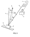
Figure 3 . It represents a plan view of the method of the invention, equivalent toFigure 1 , but in this case the reflective surface is positioned with an error in relation to the objective point, allowing to explain how the correction is made. -
Figure 4 . It shows a plan representation equivalent to the previous figure with the electromechanical device by which the reflective surface is positioned in the correct position so that the reflected light falls on the objective point. - The following is a description of the invention based on the above-mentioned figures.
- The method of the invention allows positioning of the sun in relation to the sun 1 a
reflective surface 2 mounted on anelectromechanical device 3 with rotation axes in azimuth (vertical to the floor) and elevation (parallel to the floor) employing afirst sensor 4 and asecond sensor 5 so that thelight 6 incident on thereflective surface 6 provides areflected light 7 falling on anobjective point 8. - The
first sensor 4 andsecond sensor 5 measure the angles that form the projections of the vector ofincident light 6 in relation to two orthogonal planes. - In
Figures 1 and2 , thereflective surface 2 is positioned so that the reflected light falls on the objective point. - In the case of
Figure 1 , it is shown a plan view for its application in azimuth. In this case, thefirst sensor 4 is positioned perpendicular to areference direction 9, so that though thefirst sensor 4 is measured a first azimuth angle αp corresponding to the angle that forms theincident light 6 in relation to thereference direction 9. - Regarding to the
second sensor 5, this is located solidly connected to thereflective surface 2, which it is wanted to be positioned so that the reflectedlight 7 falls on theobjective point 8. Theobjective point 8 forms a second azimuth angle γp known in relation to thereference direction 9 and its position relative to the rotation center of thesurface 2. By analyzing the geometry ofFigure 1 is achieved a third azimuth δp which must be
second sensor 5. - The application of the method in elevation is shown in
Figure 2 and the reasoning is equivalent to that described forFigure 1 . - In the case of
Figure 2 it is shown an elevation view, so that thefirst sensor 4 measures a first elevation angle αa corresponding to the angle that formsincident light 6 in relation to thereference direction 9. Usually the first elevation angle αa is different from the first azimuth angle αp, since thereference direction 9 in its plan and elevation view is composed of two projections that are different for the positioning in azimuth and elevation. - Equivalently, the
objective point 8 forms a third elevation angle γa in relation to thereference direction 9 and its relative position in relation to the rotation center of thereflective surface 2. In this case, by analyzing the geometry is obtained a third elevation angle δa measured by thesensor 5 which by geometry must be
second sensor 5. - Accordingly, the invention provides the geometry calculation of the third azimuth angle δp and the third elevation angle δa from the equations discussed, and it may also be measured by the second sensor S.
- In the
Figure 3 is shown the case in which the reflectedlight 7 does not fall on theobjective point 8. In this case through thesecond sensor 5 is measured a fourth azimuth angle δpe and a fourth elevation angle δae that forms the reflected light 7 with the axis perpendicular to thesecond sensor 5. - Next, the third azimuth angle δp is compared with the fourth azimuth angle δpe, so that in the case in which there is coincidence between both, the position of the
reflective surface 2 is not varied, and otherwise the position of the same is varied to make coincide the third azimuth angle δp and the fourth azimuth angle δpe. This same operation is performed in the case of elevation. - In the
Figure 4 is shown theelectromechanical device 3 which allows perform the correct positioning of thereflective surface 2 for its application in azimuth corresponding to that depicted inFigure 3 . In this case theelectromechanical device 3 comprises a swing motor in azimuth 3a and acontrol circuit 3b for governing the position of thereflective surface 2 so that the third azimuth angle δp and the fourth azimuth angle δpe are made coincide. - The
control circuit 3b is made by a microprocessor that takes the first azimuth angle αp and the fourth azimuth angle δpe provided by thefirst sensor 4 and thesecond sensor 5. In turn, it calculates the third azimuth angle δp, with which the sunlight should fall on thesecond sensor 5, and achieves an error of position
- Simultaneously, the same procedure is applied in relation to the vertical axis of elevation.
- Thus, by the method of the invention is achieved positioning with precision the
reflective surface 2 so that the reflectedlight 7 falls on theobjective point 8.
Claims (12)
- METHOD FOR POSITIONING A SURFACE IN RELATION TO A LIGHT SOURCE USING SENSORS, which allows the positioning of a reflective surface (2) in relation to the light source (1) so that the reflected light (7) by the reflective surface (2) falls on an objective point (8) of known position, by action of an electromechanical device (3) with two axes of rotation in azimuth and elevation; it is characterized in that comprises:- making that the reflected light (7) by the reflective surface (2) falls on the objective point (8);- measuring by a first sensor (4) located in a fixed position, a first azimuth angle (αp) and a first elevation angle (αa) forming the beam of light incident on the first sensor (4) with respect to a reference direction (9), and determining a second azimuth angle (γp) and a second elevation angle (γa), both invariable and known, forming the reflected beam (7) on the reflective surface (2) and falling on the objective point (8), in relation to the reference direction (9);- geometry calculation of a third azimuth angle (δp) from the first azimuth angle (αp) and the second azimuth angle (γp) and geometry calculation of a third elevation angle (γa) from the first elevation angle (αa) and second elevation angle (γa), corresponding the third azimuth (δp) and elevation (δa) angles to the angles which form the incident beam (6) in relation to the axis perpendicular to a second sensor (5) solidly connected to the reflective surface (2), in azimuth and elevation respectively;- at any position of the reflective surface (2), measuring by the second sensor (5), a fourth azimuth angle (δpe) and a fourth elevation angle (δae) which forms the reflected beam (7) with the axis perpendicular to the second sensor;- comparing the third azimuth angle (δp) with the fourth azimuth angle so that in the case in which there is coincidence between the third azimuth angle (δp) and the fourth azimuth angle (δpe), maintaining the position in azimuth of the reflective surface (2), and otherwise varying the position of the reflective surface (2) to make coincide the third azimuth angle (δp) and the fourth azimuth angle (δpe); and comparing the third elevation angle (δa) with the fourth elevation angle (δae) so that, in the case in which there is coincidence between the third elevation angle (δa) and the fourth elevation angle (δae), maintaining the position in elevation of the reflective surface (2), and otherwise varying the position of the reflective surface (2) to make coincide the third elevation angle (δa) and the fourth elevation angle (δae).
- METHOD FOR POSITIONING A SURFACE IN RELATION TO A LIGHT SOURCE USING SENSORS, according to the claim 1, characterized in that the light source is the sun (1).
- METHOD FOR POSITIONING A SURFACE IN RELATION TO A LIGHT SOURCE USING SENSORS, according to the claim 2, characterized in that the first sensor (4) and the second sensor (5) are angle encoder-type angle solar sensors of high precision.
- METHOD FOR POSITIONING A SURFACE IN RELATION TO A LIGHT SOURCE USING SENSORS, according to the claim 1, characterized in that comprises storing the first azimuth angle (αp), the second azimuth angle (αp) and a third azimuth angle (δp) as well as the first elevation angle (αa), second elevation angle (γa) and the third elevation angle (δa).
- METHOD FOR POSITIONING A SURFACE IN RELATION TO A LIGHT SOURCE USING SENSORS, according to the claim 1, characterized in that the reference direction (9) is a direction perpendicular to the axis of the first sensor (4).
- METHOD FOR POSITIONING A SURFACE IN RELATION TO A LIGHT SOURCE USING SENSORS, according to the claim 1, characterized in that the electromechanical device (3) governing the position of the reflective surface (2) comprises a control circuit (3b), which governs the position of positioning means of the reflective surface (2).
- METHOD FOR POSITIONING A SURFACE IN RELATION TO A LIGHT SOURCE USING SENSORS, according to the claim 1, characterized in that the positioning means of the reflective surface (2) are selected from electric motors (3a), hydraulic actuators and pneumatic actuators.
- METHOD FOR POSITIONING A SURFACE IN RELATION TO A LIGHT SOURCE USING SENSORS, according to the claim 1, characterized in that the reflective surface (2) is selected from a surface with plane, parabolic, cylinder-parabolic and hyperbolic geometry.
- METHOD FOR POSITIONING A SURFACE IN RELATION TO A LIGHT SOURCE USING SENSORS, according to the claim 1, characterized in that the azimuth and elevation axes are any axes with the same relation that said azimuth and elevation axes.
- METHOD FOR POSITIONING A SURFACE IN RELATION TO A LIGHT SOURCE USING SENSORS, according to the claim 1, characterized in that it is applied to the illumination of buildings.
- METHOD FOR POSITIONING A SURFACE IN RELATION TO A LIGHT SOURCE USING SENSORS, according to the claim 10, characterized in that the reflective surface (2) is mounted on the top floor of a building, light of which is reflected through holes of its structure.
- METHOD FOR POSITIONING A SURFACE IN RELATION TO A LIGHT SOURCE USING SENSORS, according to the claim 1, characterized in that it is applied to reflect any light source.
Applications Claiming Priority (2)
| Application Number | Priority Date | Filing Date | Title |
|---|---|---|---|
| ES200900206A ES2346172B2 (en) | 2009-01-26 | 2009-01-26 | POSITIONING PROCEDURE OF A SURFACE REGARDING A SOURCE FOUNTAIN THROUGH SENSORS |
| PCT/ES2010/000024 WO2010084224A2 (en) | 2009-01-26 | 2010-01-25 | Method for positioning a surface in relation to a light source using sensors |
Publications (2)
| Publication Number | Publication Date |
|---|---|
| EP2390747A2 true EP2390747A2 (en) | 2011-11-30 |
| EP2390747A4 EP2390747A4 (en) | 2014-03-26 |
Family
ID=42356266
Family Applications (1)
| Application Number | Title | Priority Date | Filing Date |
|---|---|---|---|
| EP10733268.6A Withdrawn EP2390747A4 (en) | 2009-01-26 | 2010-01-25 | METHOD FOR POSITIONING A SURFACE WITH A LIGHT SOURCE USING SENSORS |
Country Status (4)
| Country | Link |
|---|---|
| US (1) | US8525976B2 (en) |
| EP (1) | EP2390747A4 (en) |
| ES (1) | ES2346172B2 (en) |
| WO (1) | WO2010084224A2 (en) |
Cited By (1)
| Publication number | Priority date | Publication date | Assignee | Title |
|---|---|---|---|---|
| WO2013129299A1 (en) * | 2012-02-29 | 2013-09-06 | 三菱重工業株式会社 | Optical condenser, rotational axis setting method therefor, and heat collection apparatus and solar thermal power generation apparatus equipped with optical condenser |
Families Citing this family (1)
| Publication number | Priority date | Publication date | Assignee | Title |
|---|---|---|---|---|
| US20160146600A1 (en) * | 2013-11-22 | 2016-05-26 | Shervin Taghavi Larigani | Novel technique of displacement and rotation measurement |
Family Cites Families (9)
| Publication number | Priority date | Publication date | Assignee | Title |
|---|---|---|---|---|
| US3986021A (en) * | 1975-10-24 | 1976-10-12 | The United States Of America As Represented By The Secretary Of The Navy | Passive solar tracking system for steerable Fresnel elements |
| US4013885A (en) * | 1976-01-08 | 1977-03-22 | Sanders Associates, Inc. | Solar energy sun tracker |
| US4154219A (en) * | 1977-03-11 | 1979-05-15 | E-Systems, Inc. | Prismatic solar reflector apparatus and method of solar tracking |
| US4192583A (en) * | 1977-10-21 | 1980-03-11 | The United States Of America As Represented By The United States Department Of Energy | Solar receiver heliostat reflector having a linear drive and position information system |
| US4211922A (en) * | 1978-11-01 | 1980-07-08 | Westinghouse Electric Corp. | Heliostat guidance |
| JP3784021B2 (en) * | 2003-05-06 | 2006-06-07 | 三鷹光器株式会社 | Autonomous heliostat |
| US7115851B2 (en) * | 2004-08-30 | 2006-10-03 | Yaoming Zhang | Heliostat device |
| ES2534037T3 (en) * | 2007-03-30 | 2015-04-16 | Esolar, Inc. | System to direct incident radiation |
| DE102007031289B4 (en) * | 2007-07-05 | 2013-11-28 | Stephan Roethlin | Angular alignment apparatus |
-
2009
- 2009-01-26 ES ES200900206A patent/ES2346172B2/en active Active
-
2010
- 2010-01-25 US US13/146,116 patent/US8525976B2/en not_active Expired - Fee Related
- 2010-01-25 WO PCT/ES2010/000024 patent/WO2010084224A2/en not_active Ceased
- 2010-01-25 EP EP10733268.6A patent/EP2390747A4/en not_active Withdrawn
Cited By (3)
| Publication number | Priority date | Publication date | Assignee | Title |
|---|---|---|---|---|
| WO2013129299A1 (en) * | 2012-02-29 | 2013-09-06 | 三菱重工業株式会社 | Optical condenser, rotational axis setting method therefor, and heat collection apparatus and solar thermal power generation apparatus equipped with optical condenser |
| AU2013227164B2 (en) * | 2012-02-29 | 2015-10-15 | Mitsubishi Heavy Industries, Ltd. | Optical condenser, rotational axis setting method therefor, and heat collection apparatus and solar power generation apparatus equipped with optical condenser |
| US9441616B2 (en) | 2012-02-29 | 2016-09-13 | Mitsubishi Heavy Industries, Ltd. | Optical condenser, rotational axis setting method therefor, and heat collection apparatus and solar power generation apparatus equipped with optical condenser |
Also Published As
| Publication number | Publication date |
|---|---|
| WO2010084224A3 (en) | 2010-09-30 |
| WO2010084224A2 (en) | 2010-07-29 |
| ES2346172A1 (en) | 2010-10-11 |
| US20120050725A1 (en) | 2012-03-01 |
| ES2346172B2 (en) | 2012-03-29 |
| US8525976B2 (en) | 2013-09-03 |
| EP2390747A4 (en) | 2014-03-26 |
Similar Documents
| Publication | Publication Date | Title |
|---|---|---|
| US9182470B2 (en) | Inclinometer for a solar array and associated systems, methods, and computer program products | |
| AU2012220646B2 (en) | Solar tracker drive | |
| CN101859014B (en) | Azimuth-elevation tracking method of heliostat with reflecting mirror surface deviated from rotating center | |
| US20130048829A1 (en) | Solar concentrator positioning system and method | |
| US20150000278A1 (en) | Solar concentrator, and heat collection apparatus and solar thermal power generation apparatus including same | |
| Zhang et al. | Error analysis and auto correction of hybrid solar tracking system using photo sensors and orientation algorithm | |
| CN102506811A (en) | Image detection-based on-line detection and correction method of reflection angle of heliostat | |
| US20100018519A1 (en) | Fault monitoring based on solar tracking error | |
| CN106444868A (en) | Sunlight reference system based accurate heliostat control device and method | |
| EP2818806A1 (en) | System for positioning a reflective surface in relation to the sun, using a solar sensor and the reflected light | |
| US8525976B2 (en) | Method for positioning a surface in relation to a light source using sensors | |
| WO2005098327A1 (en) | Heliostat and method of controlling the same | |
| CN105571470A (en) | On-line detection device for integral profile of tower type solar thermal power generation heliostat | |
| CN104238577A (en) | Biaxial computer-numerical-control positioning method and system of solar panels | |
| EP1860386A1 (en) | Tracker support for devices that follow a preset path | |
| JP2011099629A (en) | Sunlight collection system and method of adjusting reflecting mirror of sunlight collection system | |
| CN106940571B (en) | Tower heliostat condensation deviation sensor | |
| Lozano-Cancelas et al. | A testbed for heliostat facets alignment by target reflection | |
| CN107368101A (en) | A kind of heliostat device and method of work based on solar tracking sensor | |
| KR20180056073A (en) | Automatic correction system during real-time operation of HelioStart field | |
| CN210321999U (en) | Solar irradiation detection system | |
| Engin et al. | Design of real time embedded PID controller for sun tracking robot manipulator | |
| Engin et al. | Sun tracking control strategy for improved reliability and performance | |
| Medyanto et al. | Automatic Heliostat Directing System Based On Microcontroller ESP32 | |
| Skouri et al. | Development of Different Sun-Tracking Systems for Displacement of Solar Concentrator Implanted in Tunisia |
Legal Events
| Date | Code | Title | Description |
|---|---|---|---|
| PUAI | Public reference made under article 153(3) epc to a published international application that has entered the european phase |
Free format text: ORIGINAL CODE: 0009012 |
|
| 17P | Request for examination filed |
Effective date: 20110809 |
|
| AK | Designated contracting states |
Kind code of ref document: A2 Designated state(s): AT BE BG CH CY CZ DE DK EE ES FI FR GB GR HR HU IE IS IT LI LT LU LV MC MK MT NL NO PL PT RO SE SI SK SM TR |
|
| DAX | Request for extension of the european patent (deleted) | ||
| A4 | Supplementary search report drawn up and despatched |
Effective date: 20140224 |
|
| RIC1 | Information provided on ipc code assigned before grant |
Ipc: G05D 3/12 20060101AFI20140218BHEP Ipc: F24J 2/38 20140101ALI20140218BHEP Ipc: F24J 2/54 20060101ALI20140218BHEP |
|
| STAA | Information on the status of an ep patent application or granted ep patent |
Free format text: STATUS: THE APPLICATION IS DEEMED TO BE WITHDRAWN |
|
| 18D | Application deemed to be withdrawn |
Effective date: 20140924 |