EP2390683A1 - Method and system for determining the rigidity of a geological layer - Google Patents
Method and system for determining the rigidity of a geological layer Download PDFInfo
- Publication number
- EP2390683A1 EP2390683A1 EP10425184A EP10425184A EP2390683A1 EP 2390683 A1 EP2390683 A1 EP 2390683A1 EP 10425184 A EP10425184 A EP 10425184A EP 10425184 A EP10425184 A EP 10425184A EP 2390683 A1 EP2390683 A1 EP 2390683A1
- Authority
- EP
- European Patent Office
- Prior art keywords
- layer
- waves
- rigidity
- geological
- seismic
- Prior art date
- Legal status (The legal status is an assumption and is not a legal conclusion. Google has not performed a legal analysis and makes no representation as to the accuracy of the status listed.)
- Granted
Links
Images



Classifications
-
- G—PHYSICS
- G01—MEASURING; TESTING
- G01V—GEOPHYSICS; GRAVITATIONAL MEASUREMENTS; DETECTING MASSES OR OBJECTS; TAGS
- G01V1/00—Seismology; Seismic or acoustic prospecting or detecting
- G01V1/40—Seismology; Seismic or acoustic prospecting or detecting specially adapted for well-logging
- G01V1/44—Seismology; Seismic or acoustic prospecting or detecting specially adapted for well-logging using generators and receivers in the same well
- G01V1/48—Processing data
Definitions
- the present invention refers to a method and to a system for determining the rigidity of a geological layer underlying another geological layer, which is preferably a surface layer delimited at the upper part by a free surface.
- the invention refers to a method and system for determining the rigidity of a geological underlying a more rigid surface layer.
- the measurement of the elastic properties, and in particular the rigidity, ⁇ , of the geological layers on which building foundations and generally building structures lie or into they are submerged, may have various applications, among which the evaluation of the stability of the ground and thus the risk of collapse or permanent deformation of a building structure in the long term and/or in the case of a seismic event.
- the classification of foundation soils according to the NEHRP (USA), Eurocode 8 (Europe) and NTC2008 (Italy) standards for designing anti seismic building structures is mainly based on the velocity of the shear waves of a homogeneous layer equivalent to the first thirty metres of depth, V s30 .
- An application of the measurement of the velocity of the elastic waves in the subsoil is the evaluation of the efficiency of the interventions for consolidating the ground beneath existent foundations, aimed at improving the elastic parameters, such as the Young's modulus and the rigidity modulus.
- Indirect techniques based on surface measurements, i.e. neither inserting detector elements into the subsoil nor extracting samples from the subsoil and measuring properties thereof in a laboratory, are often used for measuring the velocity of the elastic waves.
- indirect techniques are of seismic type, i.e. they are based on the analysis of seismic waves produced by an artificial source.
- the use of the conventional method of seismic prospection and i.e. generating - by means of suitable apparatus - longitudinal P and transverse S body waves and recording refraction thereof by the geological layers, with the ensuing identification and measurement of the elastic properties of the latter, is inefficient.
- V 1 > V 2 the body wave is not refracted parallel to the interface and shall not be re-refracted in the surface layer.
- the source is an apparatus which generates both P waves and S waves.
- the interaction between these two types of waves in proximity to a surface gives rise, at a given distance from the source, to surface waves.
- Energisation is typically actuated by means of a hammer which hits - once or several times - metal plates coupled to the surface of the ground to be explored. In this manner, wavefronts propagated through the underlying ground are generated.
- the surface layer comprising the foundations of a building structure typically has a rigidity greater than the rigidity of the underlying layer, which may be of different type (e.g. clay soil, sandy soil, etc).
- a typical value of k is 0.2, thus the waves that have explored the underlying layer return to the surface with energy in the order of 0.04 and identification thereof within the field of waves that are trapped for reflection in the first layer (whose energy is much higher, in the order of 0.8) is practically impossible. Hence, the identification of the surface waves associated to the deepest layer in the detected seismic traces and the measurement thereof are extremely difficult.
- the Applicant has realised that if the active generator source of primary waves is positioned in the underlying layer whose rigidity is intended to be measured, the energy generated in the underlying layer is mostly available for characterizing the layer itself and is transmitted to the overlying layer solely after having "explored" the underlying one.
- interface waves In particular, in case of energization in the underlying layer and in presence of an interface between two layers with different elastic properties with respect to each other (for example between two geological layers with different rigidity such as the foundation layer and the underlying layer), most of the energy is "trapped" in the underlying layer and it is represented by interface waves.
- These waves called Stoneley waves, are entirely similar to Rayleigh surface waves and they propagate beneath the interface with the overlying layer with a simultaneously vertical and horizontal oscillation motion. Due to the continuity of movements at the interface, the Stoneley waves are also extended in the upper layer, exciting - by continuity - both the horizontal and vertical movements but exponentially attenuating when moving away from the interface itself.
- the waves whose frequency coincides with that of the vibration modes of Rayleigh waves and Love waves in the overlying layer shall be least attenuated among the transmitted waves.
- the latter shall appear on the surface with more energy. In any case, given that only one fraction of energy is transmitted to the interface, to be detected on the surface, they should be generated with enough energy to be recorded.
- the Applicant has understood that by positioning the source of seismic waves in the layer whose rigidity is intended to be measured it is possible to detect at the surface the Stoneley waves, that occur at the surface as Rayleigh and Love surface waves modes.
- the present invention refers to a method for measuring the elastic waves of a geological layer according to claim 1.
- the present invention refers to a system suitable for measuring the elastic waves of a geological layer according to claim 11.
- the present invention refers to a method and to a system for measuring the rigidity of a geological layer positioned beneath the foundations of buildings and building structures in general, which constitute or are included in a surface layer delimited at the upper part by the free surface of the ground and indicated as foundation layer.
- the characterisation of the geological layers according to the method and system according to the present preferred embodiment may be performed both before a ground consolidation intervention and after the intervention with the aim of evaluating the intervention itself.
- the subsoil in the first approximation, it is possible to describe the subsoil as a stratified compound wherein the main variation of the composition and of the mechanical properties occurs along the depth, while the variation in the two horizontal directions is negligible.
- the layers are defined starting from the surface: the first layer shall be the surface one, the second shall be the underlying one and so on and so forth.
- the method according to a particular aspect of the present invention is suitable for measuring the velocity of the elastic waves in a geological system comprising at least one first layer of the subsoil 6 and a second geological layer 5 underlying with respect thereto.
- the first layer is that whose upper surface is the free surface 2.
- the interface between the upper layer (first) 6 and the lower layer (second) 5 is indicated with reference number 3.
- the first geological layer 6 is a foundation layer comprising the foundations of a building structure, for example a residential building 1.
- the system for measuring the elastic waves which are propagated in the geological system comprises a source 4 (shown in figure 3 ) apt to generate elastic body waves and an array of sensors 8 comprising a plurality of sensors 8a, 8b, ..,8j, each of which being apt to detect elastic surface waves which propagate along the free surface 2 of the ground.
- the array of sensors is a linear array in which the sensors are arranged in line at a given spacing between a sensor and the next adjacent sensor ( figure 3 ).
- the array of sensors is constituted by ten sensors with constant spacing ⁇ x.
- a plurality of sensors is to be intended comprising at least two sensors, preferably between 4 and 12 sensors.
- the spacing between the sensors may be of a different value from one sensor to another sensor or generally be non-constant.
- the method is suitable for measuring the surface waves caused by primary and secondary waves emitted by a source provided within a second geological layer underlying a first geological layer, the source being positioned at a predetermined depth greater than the thickness of the first layer, e.g. the foundation layer.
- the source is arranged at a depth t > s.
- the source is an impulse seismic source and comprises at least one explosive charge with initial velocity comprised between 300 and 700 m/s.
- the source comprises an explosive charge with an initial velocity of 500 m/s and insertion time ⁇ 1ms.
- the source 4 is positioned at a depth t, greater than the thickness s of the foundation layer, within a hole 9 (indicated in figure 3 ) which extends from the free surface through the geological system.
- a hole 9 indicated in figure 3
- the position of the source 4 along the z-axis (depth) is indicated with 7.
- the energization of the source is provided by means of a depth seismic rifle, schematically illustrated in figure 4 and indicated in its entirety with reference number 10.
- the rifle comprises a barrel 11, of length suitable to reach the depth t, which is introduced into the ground, inside the lower geological layer, into a previously made hole (e.g. hole 9 in figure 3 ).
- the length of the barrel 11 of the seismic rifle is at least 2 metres long, for example comprised between 2 and 3 metres, so as to be able to position and detonate the explosive charge, i.e. a cartridge, inside the underlying layer.
- the rifle comprises a plate 12 for laying on the ground surface, a support knob 13 and a trigger knob 14.
- the end 15 of the barrel 11 is engaged to a removable explosion chamber 16, with open bottom, into which the cartridge of the industrial type, per se known and available in the market, is inserted.
- the explosion of the cartridge may be performed by the free surface, by operating on the trigger knob 14 which mechanically hits an ignitor (not shown in the figure), generating the explosion of the cartridge, by means of a device (not shown in the figure) extending along the barrel 11.
- the sensors of the array of sensors 8 are geophones, i.e. elastic waves electromechanical transducers.
- each geophone 8a, ...., 8j is recorded separately but synchronously on the different geophones.
- a relation between the wavelength and the thickness of the explored layer holds for the surface waves and for the layer waves.
- the components with large wavelength, ⁇ provide information regarding layers with greater depths
- components with small wavelength ⁇ provide information regarding layers closer to the surface.
- V ⁇ ⁇ f holds, where V is the velocity of the waves and f the frequency thereof. Considering the same velocity, the components with large wavelength ⁇ are the low frequency ones and those with small wavelength ⁇ are the high frequency ones.
- each sensor 8a, 8b, ..., 8j is a geophone with frequency comprised between 4 and 10 Hz.
- the geophones 8a, .., 8j of the array 8 are horizontal oscillation geophones, suitable for detecting the velocity of the surface waves with transverse horizontal polarisation, i.e. Love waves.
- the geophones are vertical oscillation geophones, suitable for detecting the velocity of the Rayleigh waves.
- the measuring method comprises the generation of a shot "outside" the sensors line, i.e. the source is arranged at a predetermined distance D, defined along the direction of arrangement of the sensors (x-axis), from the nearest sensor, i.e. first sensor 8a, of the array.
- D is not smaller than 5 m, more preferably it is comprised between 6 and 20 m.
- the array of sensors is linear along an aligning direction (axis x) and the source is arranged on the extension of the sensors alignment.
- the source is not arranged aligned with the array of sensors, but it is slightly displaced with respect to the aligning position in the plane (y,z), indicated with reference number 7 in figure 2 .
- the array of sensors is developed according to a two-dimensional geometry, such as for example according to an X, T or L-shaped arrangement.
- the minimum spacing between the sensors is in relation with the minimum detectable wavelength, thus with the detectable minimum depth.
- the minimum spacing is comprised between 0.5 and 2 m.
- the sensors of the array of sensors are equally spaced from each other, with spacing ⁇ x between 0.5 and 2 m.
- the distance between the first and the last sensor of the array referred to as the detection length and indicated with L, represents the length of the detection cover of the system and it is in relation with the maximum wavelength, thus with the maximum detectable depth.
- the step of recording the surface waves is carried out according to the multi-channel analysis of surface waves (MASW) technique.
- the sensors are typically coupled to the soil by means of rods or on floors/foundations, by means of tripods.
- the sensors 8a, 8b,...,8j, synchronised in acquisition are connected, through a connection line 17, to a data acquisition line 18, preferably a digital multichannel seismograph with a number of channels at least equal to the number of sensors, which may be a commercial seismograph (e.g. Rosina produced by Micromed spa).
- the data acquisition unit may comprise or may in turn be connected with a central processing unit 19, for example a personal computer (PC).
- the acquisition of seismic traces occurs starting from the exceeding of a preset threshold ("trigger", coinciding with the instant of energization of the subsoil) and it lasts for a few seconds after said event.
- the data acquisition unit saves the data regarding a brief period preceding the exceeding of the threshold ("pre-trigger"), said period lasting a few seconds or a few fractions of a second preceding the instant when the threshold is exceeded.
- the seismic traces are recorded by each sensor as a function of the time, thus obtaining a plurality of amplitude/time signals, each signal being detected by the respective sensor of the array of sensors.
- Phase velocity spectra of the surface waves and the respective experimental dispersion curves are obtained through a transformation from the amplitude/time domain to the wave frequency/number domain (f-k) or slowness/frequency domain (p-f), or to the velocity/frequency domain (V-f), according to the processing methods known in the MASW field technique.
- Such technique is generally efficient at isolating the surface waves from the body waves (P and S), the first generally constituting the main portion of the seismic trace in presence of a sufficiently far energization.
- a dispersion curve is calculated by searching the maximum values of spectral power in the space f-k or p-f, so as to form a 2D image of the phase velocity of the Rayleigh and/or Love waves as a function of the frequency, which is in turn linked to the depth.
- the step of determining the velocity of the surface waves comprises the following steps:
- Carrying out steps 1)-4) for different test velocities produces a data matrix which is represented in a frequency two-dimensional chart-V i , generally represented coloured, where the colours are proportional to the power spectra under step 4).
- V i frequency two-dimensional chart-V i
- the maximum values in the spectral charts indicate the velocity at the various frequencies of different propagation modes of surface waves, i.e. fundamental or higher-order modes, excited by the Stoneley waves, which thus occur as surface waves, both Rayleigh and Love surface waves.
- dispersion The variation of the velocity as a function of the frequency is called dispersion.
- Figure 5 is an exemplifying image of experimental dispersion, in the phase frequency-velocity domain, obtained from the analysis of the seismic traces measured in a geological system of two layers, in which the upper layer is constituted by the foundations and has a thickness s of 1.3 m.
- two distinct high energy regions are visible (in the grey scale, the greater energy corresponds to a lighter tonality), which are substantially attributable to two dominant modes of propagation of the surface waves, Love waves in this case: a first low frequency region extended from about 20 to 30 Hz (where there is a high density of maximum energy points, represented by white circles) and a second high frequency region which is extended approximately from 35 to 80 Hz. From the maximum energy points in each region there follows the identification of dispersion curves which indicate at what phase velocity the maximum transport of energy of the Love waves occurs as a function of the frequency and thus of the explored depth.
- the first region is attributable to a first mode of the Love waves with a phase velocity of about 150 m/s and the second region is attributable to a second Love mode with a phase velocity of about 300 m/s.
- the consolidation intervention may occur for example by providing a plurality of holes through the layer of the ground to be consolidated (i.e. the lower layer 5) and subsequently injecting an expanded resin for filling the holes, according to known techniques.
- Figure 6 is the dispersion image obtained from recording the seismic traces after the consolidation intervention.
- Figure 6 shows the creation of a "channel" in which the waves not present in figure 5 travel, at a frequency between 30 and 45 Hz, i.e. an increase of rigidity in the layer in which the waves travel in this frequency range.
- the points of maximum spectral power (white circles) for the first region extend now approximately from 30 to 45 Hz with phase velocity of about 200 m/s, while the points of maximum spectral power for the second region extend from about 55 to 100 Hz, with velocity of about 300 m/s. From a comparison of the image of figure 6 with an image of figure 5 it is concluded that the phase velocity for the first mode of the Love waves, associated with the deepest layer, is increased by about 30%. Both the velocity of the Rayleigh and Love surface waves is very near to that of the shear waves S, therefore the velocity value detected through the aforedescribed method represents, with good approximation, the value of the shear velocity Vs.
- the so-called inversion process allows obtaining a theoretical dispersion curve almost similar to the experimental dispersion curve, according to algorithms, per se known, for modelling of surface waves in multilayer systems.
- the calculation procedure thus allows obtaining, the profile of shear velocity, Vs, as a function of the depth, z. From the determination of the profile of shear velocity V s (z) the rigidity of the ground is obtained, and in particular the rigidity of layer underlying the foundations, ⁇ , given by the relation (1).
Landscapes
- Physics & Mathematics (AREA)
- Life Sciences & Earth Sciences (AREA)
- Engineering & Computer Science (AREA)
- Acoustics & Sound (AREA)
- Environmental & Geological Engineering (AREA)
- Geology (AREA)
- Remote Sensing (AREA)
- General Life Sciences & Earth Sciences (AREA)
- General Physics & Mathematics (AREA)
- Geophysics (AREA)
- Geophysics And Detection Of Objects (AREA)
Abstract
Description
- The present invention refers to a method and to a system for determining the rigidity of a geological layer underlying another geological layer, which is preferably a surface layer delimited at the upper part by a free surface. In particular, the invention refers to a method and system for determining the rigidity of a geological underlying a more rigid surface layer.
- The measurement of the elastic properties, and in particular the rigidity, µ, of the geological layers on which building foundations and generally building structures lie or into they are submerged, may have various applications, among which the evaluation of the stability of the ground and thus the risk of collapse or permanent deformation of a building structure in the long term and/or in the case of a seismic event.
- The classification of foundation soils according to the NEHRP (USA), Eurocode 8 (Europe) and NTC2008 (Italy) standards for designing anti seismic building structures is mainly based on the velocity of the shear waves of a homogeneous layer equivalent to the first thirty metres of depth, Vs30. The velocities of the shear waves, Vs, is actually directly related to the rigidity of the material that forms the geological layer through the equation

- An application of the measurement of the velocity of the elastic waves in the subsoil is the evaluation of the efficiency of the interventions for consolidating the ground beneath existent foundations, aimed at improving the elastic parameters, such as the Young's modulus and the rigidity modulus.
- Indirect techniques, based on surface measurements, i.e. neither inserting detector elements into the subsoil nor extracting samples from the subsoil and measuring properties thereof in a laboratory, are often used for measuring the velocity of the elastic waves. Typically, indirect techniques are of seismic type, i.e. they are based on the analysis of seismic waves produced by an artificial source.
- Conventional approaches for measuring the velocity of the shear waves require a relatively high number of sensors, with ensuing increase of costs and the required spaces as well as practical difficulties in use in urban environments.
- Furthermore, the use of the conventional method of seismic prospection and i.e. generating - by means of suitable apparatus - longitudinal P and transverse S body waves and recording refraction thereof by the geological layers, with the ensuing identification and measurement of the elastic properties of the latter, is inefficient. As a matter of fact, the law which governs refraction at an interface between two layers is the Snell's law

- Methods for exploring the subsoil based on the study of the dispersion of elastic surface waves have been developed recently. These allow using a lower number of sensors maintaining the same accuracy and, generally, the exploration depth of the surface waves directly proportional to the wavelength. C.B. Park et al. in "Multi-channel analysis of surface waves (MASW)" published in Geophysics, vol. 64, p. 800-808. 1999, describe a multi-channel analysis of surface waves technique for determining the velocity profile of the shear waves.
- In case of technical analysis of surface waves, the source is an apparatus which generates both P waves and S waves. The interaction between these two types of waves in proximity to a surface gives rise, at a given distance from the source, to surface waves. Energisation is typically actuated by means of a hammer which hits - once or several times - metal plates coupled to the surface of the ground to be explored. In this manner, wavefronts propagated through the underlying ground are generated.
- Generally, the surface layer comprising the foundations of a building structure, indicated hereinafter also as foundation layer, typically has a rigidity greater than the rigidity of the underlying layer, which may be of different type (e.g. clay soil, sandy soil, etc).
- The applicant observed that when investigating the elastic properties of a geological layer beneath the foundations, if the source is located on the surface of the ground to be explored, the energy developed by the source mostly remains trapped in the surface layer which serves as a waveguide for the elastic waves, due to the difference regarding the high seismic impedance between the two layers. Actually, through the interface between the surface layer and the underlying layer, only a fraction k of the incident energy is transmitted, while the remaining energy (1-k) is reflected. Calculating the value of the energy trapped in the layer and transmitted in terms of surface waves is generally complex and depends on the specific geometry of the problem. In first approximation, if the difference between the rigidity - and i.e. the products of density by velocity squared, according to relation (1) - of the two layers is large only a small amount of energy is transmitted into the underlying layer and is available to be explored. The waves transmitted in the underlying layer are then retransmitted into surface, but the energy thereof is reduced at the interface between the two layers by a further factor of the order of k. In conclusion, by generating at the surface the waves to explore the underlying layer, and recording them at the surface, the energy thereof is - in first approximation - reduced by a factor k 2. For example, a typical value of k is 0.2, thus the waves that have explored the underlying layer return to the surface with energy in the order of 0.04 and identification thereof within the field of waves that are trapped for reflection in the first layer (whose energy is much higher, in the order of 0.8) is practically impossible. Hence, the identification of the surface waves associated to the deepest layer in the detected seismic traces and the measurement thereof are extremely difficult.
- The Applicant has realised that if the active generator source of primary waves is positioned in the underlying layer whose rigidity is intended to be measured, the energy generated in the underlying layer is mostly available for characterizing the layer itself and is transmitted to the overlying layer solely after having "explored" the underlying one.
- In particular, in case of energization in the underlying layer and in presence of an interface between two layers with different elastic properties with respect to each other (for example between two geological layers with different rigidity such as the foundation layer and the underlying layer), most of the energy is "trapped" in the underlying layer and it is represented by interface waves. These waves, called Stoneley waves, are entirely similar to Rayleigh surface waves and they propagate beneath the interface with the overlying layer with a simultaneously vertical and horizontal oscillation motion. Due to the continuity of movements at the interface, the Stoneley waves are also extended in the upper layer, exciting - by continuity - both the horizontal and vertical movements but exponentially attenuating when moving away from the interface itself. More specifically, the waves whose frequency coincides with that of the vibration modes of Rayleigh waves and Love waves in the overlying layer shall be least attenuated among the transmitted waves. The latter shall appear on the surface with more energy. In any case, given that only one fraction of energy is transmitted to the interface, to be detected on the surface, they should be generated with enough energy to be recorded.
- The Applicant has understood that by positioning the source of seismic waves in the layer whose rigidity is intended to be measured it is possible to detect at the surface the Stoneley waves, that occur at the surface as Rayleigh and Love surface waves modes.
- In an aspect, the present invention refers to a method for measuring the elastic waves of a geological layer according to claim 1.
- In a further aspect, the present invention refers to a system suitable for measuring the elastic waves of a geological layer according to
claim 11. - The present invention shall be described hereinafter more in detail with reference to the attached drawings, in which some but not all the embodiments are shown. The drawings illustrating the embodiments are schematic representations.
-
figure 1 represents a planar view illustrating an exemplifying arrangement of an array of sensors apt to measure the elastic properties of the subsoil beneath and/or in proximity to a building, according to an embodiment of the invention. -
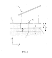
figure 2 represents a first transverse section offigure 1 along line AA. -
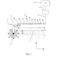
figure 3 represents a second transverse section offigure 1 along line BB. With the aim of improving clarity, the representation of the building 1 is omitted in the figure. -
figure 4 schematically shows the structure of a seismic rifle which can be used for the implementation of the method according to the present invention. -
figure 5 is an example of an image of the phase velocity of the surface waves (Love) as a function of the frequency in a situation prior to the intervention of consolidating the layer underlying the foundations. -
figure 6 is an example of an image of the phase velocity of the surface waves (Love) as a function of the frequency in a situation subsequent to the intervention of consolidating the layer underlying the foundations. - Referring to
figures 1 to 3 , in a preferred embodiment, the present invention refers to a method and to a system for measuring the rigidity of a geological layer positioned beneath the foundations of buildings and building structures in general, which constitute or are included in a surface layer delimited at the upper part by the free surface of the ground and indicated as foundation layer. The characterisation of the geological layers according to the method and system according to the present preferred embodiment may be performed both before a ground consolidation intervention and after the intervention with the aim of evaluating the intervention itself. - In the first approximation, it is possible to describe the subsoil as a stratified compound wherein the main variation of the composition and of the mechanical properties occurs along the depth, while the variation in the two horizontal directions is negligible. In this context and according to a non-limiting convention of the present invention, the layers are defined starting from the surface: the first layer shall be the surface one, the second shall be the underlying one and so on and so forth.
- The method according to a particular aspect of the present invention is suitable for measuring the velocity of the elastic waves in a geological system comprising at least one first layer of the
subsoil 6 and a second geological layer 5 underlying with respect thereto. The first layer is that whose upper surface is thefree surface 2. The interface between the upper layer (first) 6 and the lower layer (second) 5 is indicated withreference number 3. - In the embodiment illustrated in
figures 1-3 , the firstgeological layer 6 is a foundation layer comprising the foundations of a building structure, for example a residential building 1. - The system for measuring the elastic waves which are propagated in the geological system comprises a source 4 (shown in
figure 3 ) apt to generate elastic body waves and an array of sensors 8 comprising a plurality ofsensors free surface 2 of the ground. Preferably, the array of sensors is a linear array in which the sensors are arranged in line at a given spacing between a sensor and the next adjacent sensor (figure 3 ). In the example illustrated infigures 1-3 the array of sensors is constituted by ten sensors with constant spacing Δx. - However, the number of sensors comprised in the illustrated array shall not be deemed to be limitative of the present invention, such number being selected depending on the applications, for example as a function of the length of the area to be explored, as described further in detail hereinafter. In this context, a plurality of sensors is to be intended comprising at least two sensors, preferably between 4 and 12 sensors.
- In a different embodiment, the spacing between the sensors may be of a different value from one sensor to another sensor or generally be non-constant.
- According to a main aspect of the preferred embodiments of the present invention, the method is suitable for measuring the surface waves caused by primary and secondary waves emitted by a source provided within a second geological layer underlying a first geological layer, the source being positioned at a predetermined depth greater than the thickness of the first layer, e.g. the foundation layer. Referring to
figures 1-3 and called s the thickness of the first layer 6 (figure 2 , along the z-axis), the source is arranged at a depth t > s. In a preferred embodiment, the distance d from theinterface 3 between the first and the second geological layer, i.e. d = t-s, is comprised between 0.5 m and 1.5 m. - Preferably, the source is an impulse seismic source and comprises at least one explosive charge with initial velocity comprised between 300 and 700 m/s. In a preferred embodiment, the source comprises an explosive charge with an initial velocity of 500 m/s and insertion time < 1ms.
- In some embodiments, the
source 4 is positioned at a depth t, greater than the thickness s of the foundation layer, within a hole 9 (indicated infigure 3 ) which extends from the free surface through the geological system. Infigure 2 , the position of thesource 4 along the z-axis (depth) is indicated with 7. - In a preferred embodiment, the energization of the source is provided by means of a depth seismic rifle, schematically illustrated in
figure 4 and indicated in its entirety withreference number 10. The rifle comprises abarrel 11, of length suitable to reach the depth t, which is introduced into the ground, inside the lower geological layer, into a previously made hole (e.g. hole 9 infigure 3 ). For example, the length of thebarrel 11 of the seismic rifle is at least 2 metres long, for example comprised between 2 and 3 metres, so as to be able to position and detonate the explosive charge, i.e. a cartridge, inside the underlying layer. The rifle comprises aplate 12 for laying on the ground surface, asupport knob 13 and atrigger knob 14. Theend 15 of thebarrel 11 is engaged to aremovable explosion chamber 16, with open bottom, into which the cartridge of the industrial type, per se known and available in the market, is inserted. The explosion of the cartridge may be performed by the free surface, by operating on thetrigger knob 14 which mechanically hits an ignitor (not shown in the figure), generating the explosion of the cartridge, by means of a device (not shown in the figure) extending along thebarrel 11. - Preferably, the sensors of the array of sensors 8 are geophones, i.e. elastic waves electromechanical transducers.
- The signal of each
geophone 8a, ...., 8j is recorded separately but synchronously on the different geophones. A relation between the wavelength and the thickness of the explored layer holds for the surface waves and for the layer waves. Generally, the components with large wavelength, λ, provide information regarding layers with greater depths, while components with small wavelength λ provide information regarding layers closer to the surface. The relation:
- Preferably, each
sensor geophones 8a, .., 8j of the array 8 are horizontal oscillation geophones, suitable for detecting the velocity of the surface waves with transverse horizontal polarisation, i.e. Love waves. In a further embodiment the geophones are vertical oscillation geophones, suitable for detecting the velocity of the Rayleigh waves. - In the embodiment illustrated in the figures and with particular reference to
figure 3 , the measuring method comprises the generation of a shot "outside" the sensors line, i.e. the source is arranged at a predetermined distance D, defined along the direction of arrangement of the sensors (x-axis), from the nearest sensor, i.e.first sensor 8a, of the array. Preferably, with the aim of reducing or minimising the effects of the near field, D is not smaller than 5 m, more preferably it is comprised between 6 and 20 m. - Preferably , the array of sensors is linear along an aligning direction (axis x) and the source is arranged on the extension of the sensors alignment. However, in some embodiments of the present invention, the source is not arranged aligned with the array of sensors, but it is slightly displaced with respect to the aligning position in the plane (y,z), indicated with
reference number 7 infigure 2 . - In a further embodiment (not shown in the figures), the array of sensors is developed according to a two-dimensional geometry, such as for example according to an X, T or L-shaped arrangement. The minimum spacing between the sensors is in relation with the minimum detectable wavelength, thus with the detectable minimum depth. Preferably , the minimum spacing is comprised between 0.5 and 2 m.
- In an embodiment, the sensors of the array of sensors are equally spaced from each other, with spacing Δx between 0.5 and 2 m.
- The distance between the first and the last sensor of the array, referred to as the detection length and indicated with L, represents the length of the detection cover of the system and it is in relation with the maximum wavelength, thus with the maximum detectable depth.
- The step of recording the surface waves is carried out according to the multi-channel analysis of surface waves (MASW) technique. Therein, the recording of the surface waves generated by the seismic source by the plurality of receivers occurs simultaneously. The sensors are typically coupled to the soil by means of rods or on floors/foundations, by means of tripods. Referring to
figure 3 , thesensors connection line 17, to adata acquisition line 18, preferably a digital multichannel seismograph with a number of channels at least equal to the number of sensors, which may be a commercial seismograph (e.g. Rosina produced by Micromed spa). The data acquisition unit may comprise or may in turn be connected with acentral processing unit 19, for example a personal computer (PC). The acquisition of seismic traces occurs starting from the exceeding of a preset threshold ("trigger", coinciding with the instant of energization of the subsoil) and it lasts for a few seconds after said event. In an embodiment, the data acquisition unit saves the data regarding a brief period preceding the exceeding of the threshold ("pre-trigger"), said period lasting a few seconds or a few fractions of a second preceding the instant when the threshold is exceeded. - During the period of data acquisition by the data acquisition unit, the seismic traces are recorded by each sensor as a function of the time, thus obtaining a plurality of amplitude/time signals, each signal being detected by the respective sensor of the array of sensors.
- Phase velocity spectra of the surface waves and the respective experimental dispersion curves are obtained through a transformation from the amplitude/time domain to the wave frequency/number domain (f-k) or slowness/frequency domain (p-f), or to the velocity/frequency domain (V-f), according to the processing methods known in the MASW field technique. Such technique is generally efficient at isolating the surface waves from the body waves (P and S), the first generally constituting the main portion of the seismic trace in presence of a sufficiently far energization. A dispersion curve is calculated by searching the maximum values of spectral power in the space f-k or p-f, so as to form a 2D image of the phase velocity of the Rayleigh and/or Love waves as a function of the frequency, which is in turn linked to the depth.
- In particular and according to an embodiment, after recording the seismic traces, the step of determining the velocity of the surface waves comprises the following steps:
- 1) a test velocity value is hypothesised (Vi),
- 2) the traces are time translated to the different geophones by an amount (Δt) determined by the ratio between the distance of each geophone from the source and the hypothesized velocity Vi
- 3) the traces thus translated are summed, so as to calculate the function of correlation of all the traces,
- 4) a transformation of the correlated signal in the frequency domain is carried out. The spectral maxima shall indicate the frequency of the phases that have travelled at the velocity Vi.
- Carrying out steps 1)-4) for different test velocities produces a data matrix which is represented in a frequency two-dimensional chart-Vi, generally represented coloured, where the colours are proportional to the power spectra under step 4). The higher the power spectral density at a given pair of velocity and frequency, the higher the energy of the waves.
- The maximum values in the spectral charts indicate the velocity at the various frequencies of different propagation modes of surface waves, i.e. fundamental or higher-order modes, excited by the Stoneley waves, which thus occur as surface waves, both Rayleigh and Love surface waves.
- In practice, what happens is that the Stoneley waves, travelling in the interface between the underlying layer and the overlying one, are coupled with the surface waves of the same frequency, providing energy thereto. It is these surface waves with "increased energy" that are recorded in surface and provide information on the Stoneley waves and thus on the underlying layer.
- The variation of the velocity as a function of the frequency is called dispersion.
-
Figure 5 is an exemplifying image of experimental dispersion, in the phase frequency-velocity domain, obtained from the analysis of the seismic traces measured in a geological system of two layers, in which the upper layer is constituted by the foundations and has a thickness s of 1.3 m. The conditions of the experiment to whichfigure 5 refers were: an array of 10 horizontal component geophones with a vibrational frequency of 4.5 Hz arranged at a constant distance of 0.9 m from each other; an active source comprising a calibre 8 seismic rifle with exploding industrial cartridge which develops a pressure of about 1700 bars and an initial gas velocity of 500 m/s, in which the cartridge was exploded at a depth t of about 2 m and a distance D of 15 m from the first geophone of the array; the sampling of the signals was performed at a frequency of 1024 Hz. - In the image of
figure 5 , two distinct high energy regions are visible (in the grey scale, the greater energy corresponds to a lighter tonality), which are substantially attributable to two dominant modes of propagation of the surface waves, Love waves in this case: a first low frequency region extended from about 20 to 30 Hz (where there is a high density of maximum energy points, represented by white circles) and a second high frequency region which is extended approximately from 35 to 80 Hz. From the maximum energy points in each region there follows the identification of dispersion curves which indicate at what phase velocity the maximum transport of energy of the Love waves occurs as a function of the frequency and thus of the explored depth. In particular, the first region is attributable to a first mode of the Love waves with a phase velocity of about 150 m/s and the second region is attributable to a second Love mode with a phase velocity of about 300 m/s. - After the detection indicated in
figure 5 an intervention for consolidating the layer underlying the surface foundation layer was carried out. The consolidation intervention may occur for example by providing a plurality of holes through the layer of the ground to be consolidated (i.e. the lower layer 5) and subsequently injecting an expanded resin for filling the holes, according to known techniques. -
Figure 6 is the dispersion image obtained from recording the seismic traces after the consolidation intervention.Figure 6 shows the creation of a "channel" in which the waves not present infigure 5 travel, at a frequency between 30 and 45 Hz, i.e. an increase of rigidity in the layer in which the waves travel in this frequency range. As a matter of fact, it is observed that the maximum energy transfers both of the first and the second region are moved towards higher frequencies and velocities, with respect to the regions of maximum transfer of energy offigure 5 . The points of maximum spectral power (white circles) for the first region extend now approximately from 30 to 45 Hz with phase velocity of about 200 m/s, while the points of maximum spectral power for the second region extend from about 55 to 100 Hz, with velocity of about 300 m/s. From a comparison of the image offigure 6 with an image offigure 5 it is concluded that the phase velocity for the first mode of the Love waves, associated with the deepest layer, is increased by about 30%. Both the velocity of the Rayleigh and Love surface waves is very near to that of the shear waves S, therefore the velocity value detected through the aforedescribed method represents, with good approximation, the value of the shear velocity Vs. - It is thus derived that the consolidation intervention has caused an increase of the shear velocity by about 30%.
- The so-called inversion process allows obtaining a theoretical dispersion curve almost similar to the experimental dispersion curve, according to algorithms, per se known, for modelling of surface waves in multilayer systems. The calculation procedure thus allows obtaining, the profile of shear velocity, Vs, as a function of the depth, z. From the determination of the profile of shear velocity Vs(z) the rigidity of the ground is obtained, and in particular the rigidity of layer underlying the foundations, µ, given by the relation (1).
Claims (15)
- Method for determining the rigidity of a geological layer in terms of propagation velocity of the elastic waves within a geological system delimited by a free surface (2) and comprising at least one first geological layer (6) having a first rigidity and a second geological layer (5) having a second rigidity and being arranged below the first geological layer, said first and second layer being separated from each other by an interface (3), the method comprising the steps of:- positioning a source (4) apt to generate seismic waves within the second geological layer (5), whose rigidity is intended to be measured;- activating said source of seismic waves;- detecting at least one seismic signal by means of at least one sensor (8) arranged coupled with the free surface, and- determining from at least one seismic signal a shear velocity of the elastic waves in the second layer and thus indicative of the rigidity of the second layer.
- Method according to claim 1, wherein the step of determining a shear velocity of the elastic waves in the second layer comprises the following steps:- determining from at least one seismic signal the propagation velocity of surface waves caused by the seismic waves generated by said source;- determining a map of said propagation velocities of the surface waves as a function of the frequency thereof;- identifying, in the velocities map, a propagation velocity whose frequency is correlated to a depth in the geological system, and- correlating at least one propagation velocity identified in the velocities map to a shear velocity of the elastic waves in the second layer (5) and thus indicative of the rigidity of the second layer.
- Method according to claims 1 or 2, further comprising the step of calculating the rigidity from the shear velocity of the elastic waves in the second layer.
- Method according to any one of the preceding claims, wherein the rigidity value of the first layer is greater than the rigidity value of the second layer.
- Method according to any one of the preceding claims, wherein the first geological layer is delimited by the free surface and comprises the foundations of a building structure (1).
- Method according to any one of the preceding claims, wherein the first layer has a thickness (s) and said source is positioned at a depth (t) with respect to the free surface larger than the thickness of the first layer.
- Method according to any one of the preceding claims, wherein said source of seismic signal is an impulse source suitable to generate body waves.
- Method according to any one of the preceding claims, wherein the step of detecting at least one seismic signal comprises detecting a plurality of seismic signals and it is obtained by means of an array of sensors (8) comprising a plurality of sensors (8a, ...,8j) arranged coupled with the free surface (2), each sensor being apt to detect a seismic signal of the plurality of seismic signals.
- Method according to claim 8, wherein the surface waves whose propagation velocity is detected are detected through a multichannel technique.
- Method according to any one of claims 2 to 9, wherein the step of detecting at least one seismic signal comprises detecting a signal as a function of the time during a period of acquisition and the step of determining a map of the propagation velocity of the surface waves comprises performing a transformation of the seismic signal from the time domain to the frequency domain.
- System for determining the rigidity of a geological layer in terms of propagation velocity of the elastic waves within a geological system delimited by a free surface (2) and comprising at least one first geological layer (6) having a first rigidity and a second geological layer (5) having a second rigidity and being arranged below the first geological layer, said layers being separated from each other by an interface (3), the system comprising
a source suitable to generate seismic waves;
at least one seismic signal sensor (8) arranged coupled with the free surface, and
an electronic unit (18) for acquiring seismic signals detected by the at least one sensor, wherein said source is positioned in the second geological layer. - System according to claim 11, wherein the at least one seismic signal sensor is an array of seismic signal sensors (8) comprising a plurality of sensors (8a, .., 8j), the plurality including a first (8a) and a last (8j) sensor, arranged coupled with the free surface at a predetermined spacing form each other.
- System according to claim 12, wherein the sensors are aligned along an alignment direction and the source is positioned at a predetermined distance (D) from the first sensor of the linear array of sensors, defined along the alignment direction.
- System according to any one of claims 11 to 13, wherein said source is positioned in the second layer at a depth (d) comprised between 0.1 m and 2.0 m from the interface con the first layer.
- System according to any one of claims 11 to 14, wherein the source of seismic waves is energized by a depth seismic rifle (10).
Priority Applications (9)
| Application Number | Priority Date | Filing Date | Title |
|---|---|---|---|
| ES10425184T ES2787231T3 (en) | 2010-05-28 | 2010-05-28 | Method and system to determine the stiffness of a geological layer |
| EP10425184.8A EP2390683B1 (en) | 2010-05-28 | 2010-05-28 | Method and system for determining the rigidity of a geological layer |
| PT104251848T PT2390683T (en) | 2010-05-28 | 2010-05-28 | Method and system for determining the rigidity of a geological layer |
| ES11721784T ES2799885T3 (en) | 2010-05-28 | 2011-05-27 | Procedure and system to determine the stiffness of a geological layer |
| CA2800190A CA2800190A1 (en) | 2010-05-28 | 2011-05-27 | Method and system for determining the rigidity of a geological layer |
| PCT/EP2011/058743 WO2011147970A2 (en) | 2010-05-28 | 2011-05-27 | Method and system for determining the rigidity of a geological layer |
| EP11721784.4A EP2577359B1 (en) | 2010-05-28 | 2011-05-27 | Method and system for determining the rigidity of a geological layer |
| PT117217844T PT2577359T (en) | 2010-05-28 | 2011-05-27 | Method and system for determining the rigidity of a geological layer |
| US13/700,260 US20130077437A1 (en) | 2010-05-28 | 2011-05-27 | Method and system for determining the rigidity of a geological layer |
Applications Claiming Priority (1)
| Application Number | Priority Date | Filing Date | Title |
|---|---|---|---|
| EP10425184.8A EP2390683B1 (en) | 2010-05-28 | 2010-05-28 | Method and system for determining the rigidity of a geological layer |
Publications (2)
| Publication Number | Publication Date |
|---|---|
| EP2390683A1 true EP2390683A1 (en) | 2011-11-30 |
| EP2390683B1 EP2390683B1 (en) | 2020-04-08 |
Family
ID=43602878
Family Applications (2)
| Application Number | Title | Priority Date | Filing Date |
|---|---|---|---|
| EP10425184.8A Active EP2390683B1 (en) | 2010-05-28 | 2010-05-28 | Method and system for determining the rigidity of a geological layer |
| EP11721784.4A Active EP2577359B1 (en) | 2010-05-28 | 2011-05-27 | Method and system for determining the rigidity of a geological layer |
Family Applications After (1)
| Application Number | Title | Priority Date | Filing Date |
|---|---|---|---|
| EP11721784.4A Active EP2577359B1 (en) | 2010-05-28 | 2011-05-27 | Method and system for determining the rigidity of a geological layer |
Country Status (6)
| Country | Link |
|---|---|
| US (1) | US20130077437A1 (en) |
| EP (2) | EP2390683B1 (en) |
| CA (1) | CA2800190A1 (en) |
| ES (2) | ES2787231T3 (en) |
| PT (2) | PT2390683T (en) |
| WO (1) | WO2011147970A2 (en) |
Families Citing this family (4)
| Publication number | Priority date | Publication date | Assignee | Title |
|---|---|---|---|---|
| US10371840B2 (en) * | 2016-07-08 | 2019-08-06 | Sercel | Tension monitoring method and system for towed antenna |
| US10955577B2 (en) * | 2018-01-31 | 2021-03-23 | Schlumberger Technology Corporation | Systems and methods for evaluation of formation shear slowness |
| CN112285776B (en) * | 2020-10-23 | 2021-07-13 | 中国矿业大学(北京) | An automatic picking method of seismic velocity based on deep learning |
| CN117452481A (en) * | 2023-08-21 | 2024-01-26 | 北方信息控制研究院集团有限公司 | A debris flow monitoring system and method based on seismic data |
Citations (4)
| Publication number | Priority date | Publication date | Assignee | Title |
|---|---|---|---|---|
| US6094401A (en) * | 1996-03-12 | 2000-07-25 | Schlumberger Technology Corporation | Inverse vertical seismic profiling using a measurement while drilling tool as a seismic source |
| WO2004019063A2 (en) * | 2002-08-20 | 2004-03-04 | Saudi Arabian Oil Company | Use of drill bit energy for tomographic modeling of near surface layers |
| US20040226380A1 (en) * | 2003-05-13 | 2004-11-18 | Zeng Xiangwu | Measurement of base and subgrade layer stiffness using bender element technique |
| WO2008154640A1 (en) * | 2007-06-15 | 2008-12-18 | Chevron U.S.A. Inc. | Optimizing amplitude inversion utilizing statistical comparisons of seismic to well control data ' |
Family Cites Families (5)
| Publication number | Priority date | Publication date | Assignee | Title |
|---|---|---|---|---|
| US4399525A (en) * | 1979-10-05 | 1983-08-16 | Chevron Research Company | Method for interpreting well log records to yield indications of gas/oil in an earth formation such as a sandstone, limestone, or dolostone |
| US5012453A (en) * | 1990-04-27 | 1991-04-30 | Katz Lewis J | Inverse vertical seismic profiling while drilling |
| US5080190A (en) * | 1991-06-14 | 1992-01-14 | Southwest Research Institute | Reversible rigid coupling apparatus and method for borehole seismic transducers |
| US6292754B1 (en) * | 1999-11-11 | 2001-09-18 | Bp Corporation North America Inc. | Vector recomposition of seismic 3-D converted-wave data |
| US6665618B1 (en) * | 2002-08-14 | 2003-12-16 | Conocophillips Company | Seismic survey design technique |
-
2010
- 2010-05-28 ES ES10425184T patent/ES2787231T3/en active Active
- 2010-05-28 EP EP10425184.8A patent/EP2390683B1/en active Active
- 2010-05-28 PT PT104251848T patent/PT2390683T/en unknown
-
2011
- 2011-05-27 CA CA2800190A patent/CA2800190A1/en not_active Abandoned
- 2011-05-27 US US13/700,260 patent/US20130077437A1/en not_active Abandoned
- 2011-05-27 PT PT117217844T patent/PT2577359T/en unknown
- 2011-05-27 WO PCT/EP2011/058743 patent/WO2011147970A2/en not_active Ceased
- 2011-05-27 EP EP11721784.4A patent/EP2577359B1/en active Active
- 2011-05-27 ES ES11721784T patent/ES2799885T3/en active Active
Patent Citations (4)
| Publication number | Priority date | Publication date | Assignee | Title |
|---|---|---|---|---|
| US6094401A (en) * | 1996-03-12 | 2000-07-25 | Schlumberger Technology Corporation | Inverse vertical seismic profiling using a measurement while drilling tool as a seismic source |
| WO2004019063A2 (en) * | 2002-08-20 | 2004-03-04 | Saudi Arabian Oil Company | Use of drill bit energy for tomographic modeling of near surface layers |
| US20040226380A1 (en) * | 2003-05-13 | 2004-11-18 | Zeng Xiangwu | Measurement of base and subgrade layer stiffness using bender element technique |
| WO2008154640A1 (en) * | 2007-06-15 | 2008-12-18 | Chevron U.S.A. Inc. | Optimizing amplitude inversion utilizing statistical comparisons of seismic to well control data ' |
Non-Patent Citations (2)
| Title |
|---|
| C.B. PARK ET AL.: "Multi-channel analysis of surface waves (MASW)", GEOPHYSICS, vol. 64, 1999, pages 800 - 808 |
| PARK CHOON B ET AL: "Multichannel analysis of surface waves", GEOPHYSICS, SOCIETY OF EXPLORATION GEOPHYSICISTS, US, vol. 64, no. 3, 1 May 1999 (1999-05-01), pages 800 - 808, XP002466095, ISSN: 0016-8033, DOI: 10.1190/1.1444590 * |
Also Published As
| Publication number | Publication date |
|---|---|
| ES2799885T3 (en) | 2020-12-22 |
| EP2390683B1 (en) | 2020-04-08 |
| CA2800190A1 (en) | 2011-12-01 |
| US20130077437A1 (en) | 2013-03-28 |
| EP2577359B1 (en) | 2020-05-06 |
| PT2577359T (en) | 2020-07-02 |
| EP2577359A2 (en) | 2013-04-10 |
| ES2787231T3 (en) | 2020-10-15 |
| WO2011147970A3 (en) | 2012-06-28 |
| PT2390683T (en) | 2020-05-20 |
| WO2011147970A2 (en) | 2011-12-01 |
Similar Documents
| Publication | Publication Date | Title |
|---|---|---|
| Stokoe et al. | Seismic-wave-based testing in geotechnical engineering | |
| Leucci et al. | Experimental studies on the effects of fracture on the P and S wave velocity propagation in sedimentary rock (“Calcarenite del Salento”) | |
| Shirole et al. | Experimental relationship between compressional wave attenuation and surface strains in brittle rock | |
| KR20200014387A (en) | Detection of underground structures | |
| CA2706297A1 (en) | Method and system for evaluating the characteristic properties of two contacting media and of the interface between them based on mixed surface waves propagating along the interface | |
| US20140104979A1 (en) | Ground-Penetrating Tunnel-Detecting Active Sonar | |
| Zhu | Non-contact NDT of concrete structures using air coupled sensors | |
| Ghose | A microelectromechanical system digital 3C array seismic cone penetrometer | |
| EP2577359B1 (en) | Method and system for determining the rigidity of a geological layer | |
| Lee et al. | P-wave reflection imaging | |
| Zhu | Non-contact NDT of concrete structures using air-coupled sensors | |
| Heymann | Ground stiffness measurement by the continuous surface wave test | |
| JPH1068779A (en) | Nondestructive method for measuring physical properties of formation using acoustic waves | |
| Popovics et al. | Surface wave techniques for evaluation of concrete structures | |
| Pérez-Gracia et al. | Geophysics: Fundamentals and applications in structures and infrastructure | |
| JPH0820438B2 (en) | Nondestructive measurement method of physical properties of formation using acoustic wave | |
| US20220179112A1 (en) | Detecting and monitoring formation features with an optical fiber | |
| Koedel et al. | Seismic cross-hole surveying with conventional seismic and Distributed Acoustic Sensing (DAS) at the Svelvik Test-site | |
| Eikmeier et al. | Combined use of active and passive surface waves for shallow subsurface investigation in noisy urban area of São Paulo City, Brazil | |
| Niederleithinger | Seismic methods applied to ultrasonic testing in civil engineering | |
| Yan | Analysis of seismic anisotropy parameters for sedimentary rocks and strata | |
| Simpson | Non-contact measurements to estimate the elastic properties of rocks under in situ conditions | |
| Zillmer et al. | In situ seismic measurements in claystone at Tournemire (France) | |
| Butt | Ultrasonic velocity tomography method for damage evaluation in rocks | |
| RU2823220C1 (en) | Detection and observation of distinctive features of deposit formation using optical fiber |
Legal Events
| Date | Code | Title | Description |
|---|---|---|---|
| AK | Designated contracting states |
Kind code of ref document: A1 Designated state(s): AL AT BE BG CH CY CZ DE DK EE ES FI FR GB GR HR HU IE IS IT LI LT LU LV MC MK MT NL NO PL PT RO SE SI SK SM TR |
|
| AX | Request for extension of the european patent |
Extension state: BA ME RS |
|
| PUAI | Public reference made under article 153(3) epc to a published international application that has entered the european phase |
Free format text: ORIGINAL CODE: 0009012 |
|
| 17P | Request for examination filed |
Effective date: 20120322 |
|
| RAP1 | Party data changed (applicant data changed or rights of an application transferred) |
Owner name: THUR S.R.L. |
|
| STAA | Information on the status of an ep patent application or granted ep patent |
Free format text: STATUS: EXAMINATION IS IN PROGRESS |
|
| 17Q | First examination report despatched |
Effective date: 20181004 |
|
| GRAP | Despatch of communication of intention to grant a patent |
Free format text: ORIGINAL CODE: EPIDOSNIGR1 |
|
| STAA | Information on the status of an ep patent application or granted ep patent |
Free format text: STATUS: GRANT OF PATENT IS INTENDED |
|
| INTG | Intention to grant announced |
Effective date: 20191111 |
|
| GRAS | Grant fee paid |
Free format text: ORIGINAL CODE: EPIDOSNIGR3 |
|
| GRAA | (expected) grant |
Free format text: ORIGINAL CODE: 0009210 |
|
| STAA | Information on the status of an ep patent application or granted ep patent |
Free format text: STATUS: THE PATENT HAS BEEN GRANTED |
|
| AK | Designated contracting states |
Kind code of ref document: B1 Designated state(s): AL AT BE BG CH CY CZ DE DK EE ES FI FR GB GR HR HU IE IS IT LI LT LU LV MC MK MT NL NO PL PT RO SE SI SK SM TR |
|
| REG | Reference to a national code |
Ref country code: GB Ref legal event code: FG4D |
|
| REG | Reference to a national code |
Ref country code: CH Ref legal event code: EP Ref country code: AT Ref legal event code: REF Ref document number: 1255148 Country of ref document: AT Kind code of ref document: T Effective date: 20200415 |
|
| REG | Reference to a national code |
Ref country code: DE Ref legal event code: R096 Ref document number: 602010063810 Country of ref document: DE |
|
| REG | Reference to a national code |
Ref country code: IE Ref legal event code: FG4D |
|
| REG | Reference to a national code |
Ref country code: CH Ref legal event code: NV Representative=s name: VALIPAT S.A. C/O BOVARD SA NEUCHATEL, CH |
|
| REG | Reference to a national code |
Ref country code: PT Ref legal event code: SC4A Ref document number: 2390683 Country of ref document: PT Date of ref document: 20200520 Kind code of ref document: T Free format text: AVAILABILITY OF NATIONAL TRANSLATION Effective date: 20200512 |
|
| REG | Reference to a national code |
Ref country code: NL Ref legal event code: FP |
|
| REG | Reference to a national code |
Ref country code: LT Ref legal event code: MG4D |
|
| REG | Reference to a national code |
Ref country code: ES Ref legal event code: FG2A Ref document number: 2787231 Country of ref document: ES Kind code of ref document: T3 Effective date: 20201015 |
|
| PG25 | Lapsed in a contracting state [announced via postgrant information from national office to epo] |
Ref country code: IS Free format text: LAPSE BECAUSE OF FAILURE TO SUBMIT A TRANSLATION OF THE DESCRIPTION OR TO PAY THE FEE WITHIN THE PRESCRIBED TIME-LIMIT Effective date: 20200808 Ref country code: FI Free format text: LAPSE BECAUSE OF FAILURE TO SUBMIT A TRANSLATION OF THE DESCRIPTION OR TO PAY THE FEE WITHIN THE PRESCRIBED TIME-LIMIT Effective date: 20200408 Ref country code: NO Free format text: LAPSE BECAUSE OF FAILURE TO SUBMIT A TRANSLATION OF THE DESCRIPTION OR TO PAY THE FEE WITHIN THE PRESCRIBED TIME-LIMIT Effective date: 20200708 Ref country code: GR Free format text: LAPSE BECAUSE OF FAILURE TO SUBMIT A TRANSLATION OF THE DESCRIPTION OR TO PAY THE FEE WITHIN THE PRESCRIBED TIME-LIMIT Effective date: 20200709 Ref country code: SE Free format text: LAPSE BECAUSE OF FAILURE TO SUBMIT A TRANSLATION OF THE DESCRIPTION OR TO PAY THE FEE WITHIN THE PRESCRIBED TIME-LIMIT Effective date: 20200408 Ref country code: LT Free format text: LAPSE BECAUSE OF FAILURE TO SUBMIT A TRANSLATION OF THE DESCRIPTION OR TO PAY THE FEE WITHIN THE PRESCRIBED TIME-LIMIT Effective date: 20200408 |
|
| PG25 | Lapsed in a contracting state [announced via postgrant information from national office to epo] |
Ref country code: BG Free format text: LAPSE BECAUSE OF FAILURE TO SUBMIT A TRANSLATION OF THE DESCRIPTION OR TO PAY THE FEE WITHIN THE PRESCRIBED TIME-LIMIT Effective date: 20200708 Ref country code: LV Free format text: LAPSE BECAUSE OF FAILURE TO SUBMIT A TRANSLATION OF THE DESCRIPTION OR TO PAY THE FEE WITHIN THE PRESCRIBED TIME-LIMIT Effective date: 20200408 Ref country code: HR Free format text: LAPSE BECAUSE OF FAILURE TO SUBMIT A TRANSLATION OF THE DESCRIPTION OR TO PAY THE FEE WITHIN THE PRESCRIBED TIME-LIMIT Effective date: 20200408 |
|
| PG25 | Lapsed in a contracting state [announced via postgrant information from national office to epo] |
Ref country code: AL Free format text: LAPSE BECAUSE OF FAILURE TO SUBMIT A TRANSLATION OF THE DESCRIPTION OR TO PAY THE FEE WITHIN THE PRESCRIBED TIME-LIMIT Effective date: 20200408 |
|
| REG | Reference to a national code |
Ref country code: DE Ref legal event code: R097 Ref document number: 602010063810 Country of ref document: DE |
|
| PG25 | Lapsed in a contracting state [announced via postgrant information from national office to epo] |
Ref country code: DK Free format text: LAPSE BECAUSE OF FAILURE TO SUBMIT A TRANSLATION OF THE DESCRIPTION OR TO PAY THE FEE WITHIN THE PRESCRIBED TIME-LIMIT Effective date: 20200408 Ref country code: EE Free format text: LAPSE BECAUSE OF FAILURE TO SUBMIT A TRANSLATION OF THE DESCRIPTION OR TO PAY THE FEE WITHIN THE PRESCRIBED TIME-LIMIT Effective date: 20200408 Ref country code: SM Free format text: LAPSE BECAUSE OF FAILURE TO SUBMIT A TRANSLATION OF THE DESCRIPTION OR TO PAY THE FEE WITHIN THE PRESCRIBED TIME-LIMIT Effective date: 20200408 Ref country code: MC Free format text: LAPSE BECAUSE OF FAILURE TO SUBMIT A TRANSLATION OF THE DESCRIPTION OR TO PAY THE FEE WITHIN THE PRESCRIBED TIME-LIMIT Effective date: 20200408 Ref country code: CZ Free format text: LAPSE BECAUSE OF FAILURE TO SUBMIT A TRANSLATION OF THE DESCRIPTION OR TO PAY THE FEE WITHIN THE PRESCRIBED TIME-LIMIT Effective date: 20200408 Ref country code: RO Free format text: LAPSE BECAUSE OF FAILURE TO SUBMIT A TRANSLATION OF THE DESCRIPTION OR TO PAY THE FEE WITHIN THE PRESCRIBED TIME-LIMIT Effective date: 20200408 |
|
| PLBE | No opposition filed within time limit |
Free format text: ORIGINAL CODE: 0009261 |
|
| STAA | Information on the status of an ep patent application or granted ep patent |
Free format text: STATUS: NO OPPOSITION FILED WITHIN TIME LIMIT |
|
| PG25 | Lapsed in a contracting state [announced via postgrant information from national office to epo] |
Ref country code: PL Free format text: LAPSE BECAUSE OF FAILURE TO SUBMIT A TRANSLATION OF THE DESCRIPTION OR TO PAY THE FEE WITHIN THE PRESCRIBED TIME-LIMIT Effective date: 20200408 Ref country code: SK Free format text: LAPSE BECAUSE OF FAILURE TO SUBMIT A TRANSLATION OF THE DESCRIPTION OR TO PAY THE FEE WITHIN THE PRESCRIBED TIME-LIMIT Effective date: 20200408 |
|
| 26N | No opposition filed |
Effective date: 20210112 |
|
| PG25 | Lapsed in a contracting state [announced via postgrant information from national office to epo] |
Ref country code: LU Free format text: LAPSE BECAUSE OF NON-PAYMENT OF DUE FEES Effective date: 20200528 |
|
| PG25 | Lapsed in a contracting state [announced via postgrant information from national office to epo] |
Ref country code: SI Free format text: LAPSE BECAUSE OF FAILURE TO SUBMIT A TRANSLATION OF THE DESCRIPTION OR TO PAY THE FEE WITHIN THE PRESCRIBED TIME-LIMIT Effective date: 20200408 |
|
| REG | Reference to a national code |
Ref country code: AT Ref legal event code: UEP Ref document number: 1255148 Country of ref document: AT Kind code of ref document: T Effective date: 20200408 |
|
| PG25 | Lapsed in a contracting state [announced via postgrant information from national office to epo] |
Ref country code: TR Free format text: LAPSE BECAUSE OF FAILURE TO SUBMIT A TRANSLATION OF THE DESCRIPTION OR TO PAY THE FEE WITHIN THE PRESCRIBED TIME-LIMIT Effective date: 20200408 Ref country code: MT Free format text: LAPSE BECAUSE OF FAILURE TO SUBMIT A TRANSLATION OF THE DESCRIPTION OR TO PAY THE FEE WITHIN THE PRESCRIBED TIME-LIMIT Effective date: 20200408 Ref country code: CY Free format text: LAPSE BECAUSE OF FAILURE TO SUBMIT A TRANSLATION OF THE DESCRIPTION OR TO PAY THE FEE WITHIN THE PRESCRIBED TIME-LIMIT Effective date: 20200408 |
|
| PG25 | Lapsed in a contracting state [announced via postgrant information from national office to epo] |
Ref country code: MK Free format text: LAPSE BECAUSE OF FAILURE TO SUBMIT A TRANSLATION OF THE DESCRIPTION OR TO PAY THE FEE WITHIN THE PRESCRIBED TIME-LIMIT Effective date: 20200408 |
|
| P01 | Opt-out of the competence of the unified patent court (upc) registered |
Effective date: 20230602 |
|
| PGFP | Annual fee paid to national office [announced via postgrant information from national office to epo] |
Ref country code: PT Payment date: 20230519 Year of fee payment: 14 Ref country code: NL Payment date: 20230519 Year of fee payment: 14 Ref country code: IT Payment date: 20230522 Year of fee payment: 14 Ref country code: IE Payment date: 20230522 Year of fee payment: 14 Ref country code: FR Payment date: 20230526 Year of fee payment: 14 Ref country code: DE Payment date: 20230519 Year of fee payment: 14 Ref country code: CH Payment date: 20230605 Year of fee payment: 14 |
|
| REG | Reference to a national code |
Ref country code: NL Ref legal event code: HC Owner name: THUR S.A.S. DI THUR RESINS SRL; IT Free format text: DETAILS ASSIGNMENT: CHANGE OF OWNER(S), CHANGE OF OWNER(S) NAME; FORMER OWNER NAME: THUR S.R.L. Effective date: 20230731 |
|
| REG | Reference to a national code |
Ref country code: DE Ref legal event code: R081 Ref document number: 602010063810 Country of ref document: DE Owner name: THUR S.A.S. DI THUR RESINS SRL, IT Free format text: FORMER OWNER: THUR S.R.L., VERONA, IT |
|
| REG | Reference to a national code |
Ref country code: BE Ref legal event code: HC Owner name: THUR S.A.S. DI THUR RESINS SRL; IT Free format text: DETAILS ASSIGNMENT: CHANGE OF OWNER(S), CHANGE OF OWNER(S) NAME; FORMER OWNER NAME: THUR S.R.L. Effective date: 20230801 |
|
| PGFP | Annual fee paid to national office [announced via postgrant information from national office to epo] |
Ref country code: AT Payment date: 20230522 Year of fee payment: 14 |
|
| P02 | Opt-out of the competence of the unified patent court (upc) changed |
Effective date: 20230821 |
|
| PGFP | Annual fee paid to national office [announced via postgrant information from national office to epo] |
Ref country code: BE Payment date: 20230519 Year of fee payment: 14 |
|
| PGFP | Annual fee paid to national office [announced via postgrant information from national office to epo] |
Ref country code: GB Payment date: 20230524 Year of fee payment: 14 Ref country code: ES Payment date: 20230724 Year of fee payment: 14 |
|
| REG | Reference to a national code |
Ref country code: AT Ref legal event code: PC Ref document number: 1255148 Country of ref document: AT Kind code of ref document: T Owner name: THUR S.A.S. DI THUR RESINS S.R.L., IT Effective date: 20230928 |
|
| REG | Reference to a national code |
Ref country code: ES Ref legal event code: PC2A Owner name: THUR S.A.S. DI THUR RESINS S.R.L. Effective date: 20240425 |
|
| REG | Reference to a national code |
Ref country code: DE Ref legal event code: R119 Ref document number: 602010063810 Country of ref document: DE |
|
| PG25 | Lapsed in a contracting state [announced via postgrant information from national office to epo] |
Ref country code: PT Free format text: LAPSE BECAUSE OF NON-PAYMENT OF DUE FEES Effective date: 20241128 |
|
| REG | Reference to a national code |
Ref country code: CH Ref legal event code: PL |
|
| PG25 | Lapsed in a contracting state [announced via postgrant information from national office to epo] |
Ref country code: PT Free format text: LAPSE BECAUSE OF NON-PAYMENT OF DUE FEES Effective date: 20241128 |
|
| REG | Reference to a national code |
Ref country code: NL Ref legal event code: MM Effective date: 20240601 |
|
| REG | Reference to a national code |
Ref country code: AT Ref legal event code: MM01 Ref document number: 1255148 Country of ref document: AT Kind code of ref document: T Effective date: 20240528 |
|
| PG25 | Lapsed in a contracting state [announced via postgrant information from national office to epo] |
Ref country code: AT Free format text: LAPSE BECAUSE OF NON-PAYMENT OF DUE FEES Effective date: 20240528 |
|
| GBPC | Gb: european patent ceased through non-payment of renewal fee |
Effective date: 20240528 |
|
| PG25 | Lapsed in a contracting state [announced via postgrant information from national office to epo] |
Ref country code: AT Free format text: LAPSE BECAUSE OF NON-PAYMENT OF DUE FEES Effective date: 20240528 Ref country code: CH Free format text: LAPSE BECAUSE OF NON-PAYMENT OF DUE FEES Effective date: 20240531 |
|
| PG25 | Lapsed in a contracting state [announced via postgrant information from national office to epo] |
Ref country code: NL Free format text: LAPSE BECAUSE OF NON-PAYMENT OF DUE FEES Effective date: 20240601 |
|
| REG | Reference to a national code |
Ref country code: BE Ref legal event code: MM Effective date: 20240531 |
|
| PG25 | Lapsed in a contracting state [announced via postgrant information from national office to epo] |
Ref country code: DE Free format text: LAPSE BECAUSE OF NON-PAYMENT OF DUE FEES Effective date: 20241203 |
|
| PG25 | Lapsed in a contracting state [announced via postgrant information from national office to epo] |
Ref country code: IE Free format text: LAPSE BECAUSE OF NON-PAYMENT OF DUE FEES Effective date: 20240528 |
|
| PG25 | Lapsed in a contracting state [announced via postgrant information from national office to epo] |
Ref country code: BE Free format text: LAPSE BECAUSE OF NON-PAYMENT OF DUE FEES Effective date: 20240531 |
|
| PG25 | Lapsed in a contracting state [announced via postgrant information from national office to epo] |
Ref country code: FR Free format text: LAPSE BECAUSE OF NON-PAYMENT OF DUE FEES Effective date: 20240531 |
|
| PG25 | Lapsed in a contracting state [announced via postgrant information from national office to epo] |
Ref country code: IT Free format text: LAPSE BECAUSE OF NON-PAYMENT OF DUE FEES Effective date: 20240528 Ref country code: GB Free format text: LAPSE BECAUSE OF NON-PAYMENT OF DUE FEES Effective date: 20240528 |
|
| REG | Reference to a national code |
Ref country code: ES Ref legal event code: FD2A Effective date: 20250703 |
|
| PG25 | Lapsed in a contracting state [announced via postgrant information from national office to epo] |
Ref country code: ES Free format text: LAPSE BECAUSE OF NON-PAYMENT OF DUE FEES Effective date: 20240529 |