EP2390529B1 - Suspension unit - Google Patents
Suspension unit Download PDFInfo
- Publication number
- EP2390529B1 EP2390529B1 EP11167319.0A EP11167319A EP2390529B1 EP 2390529 B1 EP2390529 B1 EP 2390529B1 EP 11167319 A EP11167319 A EP 11167319A EP 2390529 B1 EP2390529 B1 EP 2390529B1
- Authority
- EP
- European Patent Office
- Prior art keywords
- rebound
- jounce
- volume
- suspension unit
- fluid
- Prior art date
- Legal status (The legal status is an assumption and is not a legal conclusion. Google has not performed a legal analysis and makes no representation as to the accuracy of the status listed.)
- Active
Links
Images

Classifications
-
- B—PERFORMING OPERATIONS; TRANSPORTING
- B60—VEHICLES IN GENERAL
- B60G—VEHICLE SUSPENSION ARRANGEMENTS
- B60G3/00—Resilient suspensions for a single wheel
- B60G3/02—Resilient suspensions for a single wheel with a single pivoted arm
- B60G3/12—Resilient suspensions for a single wheel with a single pivoted arm the arm being essentially parallel to the longitudinal axis of the vehicle
- B60G3/14—Resilient suspensions for a single wheel with a single pivoted arm the arm being essentially parallel to the longitudinal axis of the vehicle the arm being rigid
- B60G3/145—Resilient suspensions for a single wheel with a single pivoted arm the arm being essentially parallel to the longitudinal axis of the vehicle the arm being rigid the arm forming the axle housing
-
- F—MECHANICAL ENGINEERING; LIGHTING; HEATING; WEAPONS; BLASTING
- F16—ENGINEERING ELEMENTS AND UNITS; GENERAL MEASURES FOR PRODUCING AND MAINTAINING EFFECTIVE FUNCTIONING OF MACHINES OR INSTALLATIONS; THERMAL INSULATION IN GENERAL
- F16F—SPRINGS; SHOCK-ABSORBERS; MEANS FOR DAMPING VIBRATION
- F16F9/00—Springs, vibration-dampers, shock-absorbers, or similarly-constructed movement-dampers using a fluid or the equivalent as damping medium
- F16F9/06—Springs, vibration-dampers, shock-absorbers, or similarly-constructed movement-dampers using a fluid or the equivalent as damping medium using both gas and liquid
- F16F9/064—Units characterised by the location or shape of the expansion chamber
-
- B—PERFORMING OPERATIONS; TRANSPORTING
- B62—LAND VEHICLES FOR TRAVELLING OTHERWISE THAN ON RAILS
- B62D—MOTOR VEHICLES; TRAILERS
- B62D55/00—Endless track vehicles
- B62D55/08—Endless track units; Parts thereof
- B62D55/104—Suspension devices for wheels, rollers, bogies or frames
- B62D55/112—Suspension devices for wheels, rollers, bogies or frames with fluid springs, e.g. hydraulic pneumatic
-
- B—PERFORMING OPERATIONS; TRANSPORTING
- B62—LAND VEHICLES FOR TRAVELLING OTHERWISE THAN ON RAILS
- B62D—MOTOR VEHICLES; TRAILERS
- B62D55/00—Endless track vehicles
- B62D55/08—Endless track units; Parts thereof
- B62D55/104—Suspension devices for wheels, rollers, bogies or frames
-
- F—MECHANICAL ENGINEERING; LIGHTING; HEATING; WEAPONS; BLASTING
- F16—ENGINEERING ELEMENTS AND UNITS; GENERAL MEASURES FOR PRODUCING AND MAINTAINING EFFECTIVE FUNCTIONING OF MACHINES OR INSTALLATIONS; THERMAL INSULATION IN GENERAL
- F16F—SPRINGS; SHOCK-ABSORBERS; MEANS FOR DAMPING VIBRATION
- F16F9/00—Springs, vibration-dampers, shock-absorbers, or similarly-constructed movement-dampers using a fluid or the equivalent as damping medium
- F16F9/06—Springs, vibration-dampers, shock-absorbers, or similarly-constructed movement-dampers using a fluid or the equivalent as damping medium using both gas and liquid
- F16F9/064—Units characterised by the location or shape of the expansion chamber
- F16F9/065—Expansion chamber provided on the upper or lower end of a damper, separately there from or laterally on the damper
-
- F—MECHANICAL ENGINEERING; LIGHTING; HEATING; WEAPONS; BLASTING
- F16—ENGINEERING ELEMENTS AND UNITS; GENERAL MEASURES FOR PRODUCING AND MAINTAINING EFFECTIVE FUNCTIONING OF MACHINES OR INSTALLATIONS; THERMAL INSULATION IN GENERAL
- F16F—SPRINGS; SHOCK-ABSORBERS; MEANS FOR DAMPING VIBRATION
- F16F9/00—Springs, vibration-dampers, shock-absorbers, or similarly-constructed movement-dampers using a fluid or the equivalent as damping medium
- F16F9/32—Details
- F16F9/50—Special means providing automatic damping adjustment, i.e. self-adjustment of damping by particular sliding movements of a valve element, other than flexions or displacement of valve discs; Special means providing self-adjustment of spring characteristics
- F16F9/52—Special means providing automatic damping adjustment, i.e. self-adjustment of damping by particular sliding movements of a valve element, other than flexions or displacement of valve discs; Special means providing self-adjustment of spring characteristics in case of change of temperature
-
- B—PERFORMING OPERATIONS; TRANSPORTING
- B60—VEHICLES IN GENERAL
- B60G—VEHICLE SUSPENSION ARRANGEMENTS
- B60G2200/00—Indexing codes relating to suspension types
- B60G2200/10—Independent suspensions
- B60G2200/13—Independent suspensions with longitudinal arms only
- B60G2200/132—Independent suspensions with longitudinal arms only with a single trailing arm
-
- B—PERFORMING OPERATIONS; TRANSPORTING
- B60—VEHICLES IN GENERAL
- B60G—VEHICLE SUSPENSION ARRANGEMENTS
- B60G2300/00—Indexing codes relating to the type of vehicle
- B60G2300/32—Track vehicles
Definitions
- This invention relates to a suspension unit, and is particularly, although not exclusively, concerned with a suspension unit for use on a tracked vehicle.
- a tracked vehicle has a track extending around a series of track guide wheels. At least some of the guide wheels support the weight of the vehicle hull on the section of the track which is in contact with the ground.
- the expression "hull” is used to refer to the main body of the vehicle. The hull serves the same purpose as the chassis of a conventional vehicle, whether or not the chassis is constituted wholly or partially by the bodywork of the vehicle. Consequently, in the context of the present invention, the word “hull” is considered to be equivalent to a vehicle chassis.
- the track guide wheels which support the weight of the vehicle on the ground need to be connected to the vehicle hull by a suspension arrangement which enables the track guide wheel to move upwardly and downwardly relatively to the hull.
- a gas spring is used to support the vehicle load and the ride height of the vehicle is governed by the volume of the gas in the gas spring. While such a suspension unit is suitable for certain applications, when the temperature of the gas changes, the volume of the gas will also change. Such a temperature change will therefore cause the ride height of the vehicle to change. For example, a temperature change of over 40oC may occur between day and night temperatures in some climates. This may mean that the ride height of a static vehicle may decrease overnight as the temperature drops which can result in the vehicle becoming grounded and therefore immovable. It is therefore desirable to provide a suspension unit for a vehicle which can maintain a constant ride height over a range of temperatures.
- EP 1 657 470 which is considered the closest prior art, discloses a spring unit which has two pneumatic springs, where one of the springs is operative between a fully spring deflected condition and a static condition of the unit.
- the spring is dimensioned such that it is released up to the static condition under static load.
- the other spring is operative between the static condition and a fully released condition and dimensioned such that it is not released beyond the static condition.
- the spring is disconnected by a blocking unit with exceedence of the static condition.
- FR 2 609 130 discloses a valve comprising a tubular body containing a hollow slide mounted axially slidably in a sleeve, itself sliding in the body along the axis of the valve, a spring bearing on the body and pushing the slide up against an annular end of the sleeve, normally held by means of its opposite end up against a cover for closing the body on the opposite side to its central orifice; the cover and the sleeve have radial ports, the body being contained in a tubular casing having conduits, fluid passages also being provided to allow the valve to open in both directions as a result of the hydraulic pressure.
- US 3 614 125 discloses a hydraulically actuates, independent roadarm suspension system wherein hydraulic fluid is supplied to any individual roadarm actuator by a hydraulic pump and reservoir contained within the roadarm. This provides vehicles, such as military tanks, with a suspension system that keeps to a minimum the requirement for interior body space for suspension components and eliminates the need for hydraulic fluid conduits within the hull.
- EP 0 197 859 discloses a suspension element comprising an arm through which extends a wheel stub-axle of the vehicle which is rotatively mounted on a fixed part integral with the chassis of the vehicle with interposition of bearing means between the fixed part and the arm, a hydraulic chamber being provided in the arm and containing a slidable piston on which is pivotally mounted a link whose end opposed to the piston is pivotally mounted on the fixed part.
- the bearing means comprise a bearing bush surrounding the fixed part and internally coated with a material for a high resistance dry sliding, the bush being apertured for allowing the arm to oscillate on each side of a lug of the fixed part which radially projects from the bush and is pivotally mounted on the link.
- EP 0 554 147 discloses an assembly for suspension of heavy vehicles, esp. tracked vehicles - including an arm mounted movably on a structure fixed to vehicle chassis, with the oscillating arm having a hydrostatic compression shock absorber mounted on it.
- the damping and spring functions are decoupled to make the unit less sensitive to temperature fluctuations.
- the present invention is defined in the attached independent claim to which reference should now be made. Further, preferred features may be found in the sub-claims appended thereto.
- a suspension unit comprising: a resilient arrangement comprising a chamber having a primary volume arranged to contain a primary fluid; jounce and rebound variable volumes arranged to contain jounce and rebound fluids respectively; a piston slidably disposed in the chamber so as to act on the primary fluid; a jounce moveable member which separates the primary and jounce volumes and which is moveable so as to alter the jounce variable volume; a rebound moveable member which separates the primary and rebound volumes and which is moveable so as to alter the rebound variable volume; a jounce abutment member arranged to limit the movement of the jounce moveable member so as to define the maximum volume of the jounce variable volume; wherein the jounce moveable member is moveable relative to the jounce abutment member; characterised in that it further comprises a rebound abutment member arranged to limit the movement of the rebound moveable member so as to define the minimum volume of the rebound variable volume; wherein the rebound moveable member is
- the jounce moveable member can be arranged such that the jounce fluid acts on one side of the jounce moveable member and the primary fluid acts on the other side of the jounce moveable member and the rebound moveable member can be arranged such that the rebound fluid acts on one side of the rebound moveable member and the primary fluid acts on the other side of the rebound moveable member.
- the jounce moveable member When the piston moves in the jounce direction, the jounce moveable member may move away from the jounce abutment member, thereby reducing the volume of the jounce variable volume, and the rebound moveable member may abut the rebound abutment member.
- the jounce moveable member When the piston moves in the rebound direction, the jounce moveable member may abut the jounce abutment member and the rebound moveable member may move away from the rebound abutment member, thereby increasing the volume of the rebound variable volume.
- the primary volume contains a primary fluid and the jounce and rebound volumes contain jounce and rebound fluids respectively.
- the pressures of the fluids can be set such that when the piston is in the static position, the force generated by the static pressure of the primary fluid acting on the rebound moveable member is higher than the force generated by the pressure of the rebound fluid acting on the rebound moveable member and the force generated by the static pressure of the primary fluid acting on the jounce moveable member is lower than the force generated by the pressure of the jounce fluid acting on the jounce moveable member over a temperature range.
- the temperature range may be at least 10 centigrade degrees, or at least 20 centigrade degrees, or at least 30 centigrade degrees, or at least 40 centigrade degrees, or at least 50 centigrade degrees.
- the primary fluid and/or the jounce fluid and/or the rebound fluid may be a hydraulic fluid, such as oil or a gas such as nitrogen.
- the chamber may be defined by a first cylinder within which the piston is disposed and a second cylinder, wherein the jounce and rebound moveable members are disposed in the second cylinder, and wherein the interior of the first cylinder is in fluid communication with a volume in the second cylinder located between the jounce and rebound moveable members through a fluid passageway.
- the suspension unit may further comprise an internal cylinder which is disposed within the second cylinder and within which the rebound or jounce moveable member is disposed, wherein a portion of the fluid passageway is defined between an outer wall of the internal cylinder and the inner wall of the second cylinder.
- the first and second cylinders may be substantially parallel.
- the jounce and/or rebound moveable member may a piston slidably disposed in the chamber.
- the jounce and/or rebound abutment member may be a shoulder, such as an annular shoulder formed in the chamber wall, or an end stop.
- the suspension unit may further comprise a primary volume port and/or a jounce volume port and/or a rebound volume port for injecting fluid into (or removing fluid from) the respective volume.
- These ports allow fluid to be injected into or withdrawn from the respective volumes so as to alter the characteristic of the suspension unit. For example, the ride height of the vehicle can be changed by changing the amount of primary fluid, such as oil, within the primary volume.
- the suspension unit may further comprise a hub and a suspension arm which is mounted on the hub for pivoting movement about an axis of the hub, the suspension arm being provided with a wheel-supporting shaft which is parallel to and spaced from the hub axis, and wherein the resilient arrangement is accommodated within the suspension arm, wherein the piston is connected by a connecting rod to a crank pin supported by the hub at a position spaced from the hub axis, whereby pivoting of the suspension arm about the hub is accompanied by displacement of the piston.
- the invention also concerns a vehicle having a suspension unit in accordance with any statement herein.
- the vehicle may be a tracked vehicle, the suspension unit supporting a track guide wheel of the vehicle.
- the invention may comprise any combination of the features and/or limitations referred to herein, except combinations of such features as are mutually exclusive.
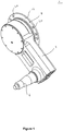
- the suspension unit 1 comprises a suspension arm 2 which is rotatable at one end about a hub 4 (not shown in Figure 1 ) which is provided with a connector element 8 having a flange 16. At the other end, the suspension arm 2 is provided with a wheel-supporting shaft 6.
- the connector element 8 When the suspension unit is mounted on a vehicle, the connector element 8 is secured to the vehicle hull or chassis (not shown) by means of bolts which pass through countersunk holes 20 in the flange 16 into screw threaded holes in the vehicle hull.
- the suspension arm 2, with the hub 4 and all other internal components, is preassembled and supplied as a unit.
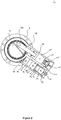
- the suspension arm 2 accommodates a resilient arrangement 37 which is shown in Figures 2 to 4 .
- the resilient arrangement 37 comprises a chamber having a primary volume, a rebound variable volume 58 and a jounce variable volume 60.
- the chamber is defined by a first cylinder 40 and a second cylinder 48 which is substantially parallel to the first cylinder 40.
- a piston 38 is slidably displaceable in the first cylinder 38 and is attached to one end of a connecting rod 36.
- the other end of the connecting rod 26 is connected to a crank pin 34 which is carried by the hub 4.
- a rebound moveable member in the form of a rebound piston 56 is slidably disposed in the second cylinder 48.
- the rebound variable volume 58 is defined between a first end 47 of the second cylinder 48 and the rebound piston 56.
- the annular shoulder 57 defines the minimum volume of the rebound variable volume 58.
- An internal cylinder 50 is disposed in the second cylinder 48 on the side opposite the rebound variable volume 58.
- a jounce moveable member in the form of a jounce piston 54 is slidably disposed in the internal cylinder 50.
- the jounce variable volume 60 is defined between an end 53 of the internal cylinder 50 and the jounce piston 54.
- a jounce abutment member in the form of an end stop 55 is screwed into the end of the internal cylinder 50 and limits the movement of the jounce piston 54 away from the end 53 of the internal cylinder 50.
- the end stop 55 defines the maximum volume of the jounce variable volume 60.
- the internal cylinder 50 is spaced from the inner surface of the second cylinder 48 over the majority of its length so as to define an annular fluid passageway 46 between the inner surface of the second cylinder 48 and the outer surface of the internal cylinder 50.
- An end 51 of the internal cylinder 50 contacts the inner surface of the second cylinder 48 and is provided with axially extending passageways 52 that provide fluid communication between the annular fluid passageway 46 and an intermediate volume 49 in the second cylinder 48 that is located between the jounce piston 54 and the rebound piston 56.
- the internal volume 41 of the first cylinder 40 communicates with the intermediate volume 49 through a damping unit 42, a passageway 44 which fluidly connects the first and second cylinders, the annular passageway 46 and the axially extending passageways 52.
- the suspension unit 1 is provided with a primary volume port 43, a rebound volume port 59 and a jounce volume port 61. These ports 43, 59, 61 allow fluid to be injected into the respective volumes, or removed from the volumes as necessary.
- the ports 43, 49, 61 are essentially a fluid passageway with a valve disposed therein which is opened when fluid is injected into or removed from the volume.
- a primary fluid in the form of oil or other hydraulic fluid fills the internal volume 41 of the first cylinder 40 to the right of the first piston 38 as seen in Figure 2 , the damping unit 42, the passageway 44, the annular fluid passageway 46, the axially extending passageways 52 and the intermediate volume 49.
- the volume filled by the oil is collectively referred to as the primary volume.
- Gas, such as nitrogen, under pressure is present in the rebound and jounce variable volumes 58 and 60. The quantity of gas in the volumes 58 and 60 is selected to achieve the characteristics described below.
- the suspension unit functions as follows.
- the piston 38 In the static condition (ie when the suspension unit is supporting the weight of the vehicle and the vehicle is static) shown in Figure 2 , the piston 38 is situated approximately midway along the first cylinder 40 and acts on the oil (primary fluid) in the primary volume with the weight of the vehicle.
- the pressure of the gas (jounce fluid) in the jounce volume 60 is greater than the pressure of the oil and therefore the jounce piston 54 is abuts the end stop 55. This means that the jounce variable volume 60 is at a maximum.
- the pressure of the gas (rebound fluid) in the rebound volume 58 is less than the pressure of the oil and therefore the rebound piston 56 abuts the shoulder 57. This means that the rebound variable volume 58 is at a minimum.
- the height of the vehicle hull above the ground is determined by the amount of oil in the primary volume.
- more oil can be injected into the primary volume through the injection port 43, so as to force the arm 2 to rotate in the clockwise direction about the hub 4. Consequently, in order to lower the ride height of the vehicle, oil can be removed from the primary volume through the injection port 43.
- the pressure of the oil in the primary volume increases and acts on both the jounce and rebound pistons 54, 56.
- the pressure of the oil during jounce rises above the pressure of the gas in the rebound volume 58 that is separated from the oil by the rebound piston 56.
- the rebound volume 58 is at a minimum and the rebound piston 56 cannot move.
- the increase in pressure of the oil acting on the jounce piston 54 causes the gas in the jounce volume 60 to be compressed and therefore the jounce piston 54 begins to move away from the end stop 55.
- the jounce variable volume 60 is reduced by the movement of the jounce piston 54 such that the pressure of the gas in the jounce volume 60 is the same as the pressure of the oil.
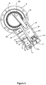
- Figure 4 shows the rebound condition, in which the track guide wheel mounted on the shaft 6 moves away from the static condition in the direction of increasing distance of the track guide wheel from the vehicle hull.
- the piston 38 moves away from the damping unit 42, so that oil is drawn from the second cylinder 48 into the first cylinder 40.
- the pressure of the oil falls below the pressure of the gas in the jounce volume 54 and therefore the jounce piston 54 abuts the end stop 55 of the internal cylinder 50, so its position does not change during rebound beyond the static position.
- the reduction in pressure of the oil acting on the rebound piston 56 allows the gas in the rebound volume 58 to expand and therefore the rebound piston begins to move away from the shoulder 57.
- the rebound variable volume 58 is increased by the movement of the rebound piston 56 such that the pressure of the gas in the rebound volume 58 is the same as the pressure of the oil.
- the suspension unit 1 is able to accommodate relatively large ambient temperature changes at the static position without the ride height of the vehicle changing.
- the pressure of the gas in the rebound volume 58 and the pressure of the gas in the jounce volume 60 reduces.
- the jounce volume 60 is charged with a quantity of gas such that, at the minimum temperature of operation, the pressure is still greater than the static pressure of the oil. Since the pressure of the gas in the jounce volume 60 is greater than that of the oil in the primary volume, the jounce piston 54 is forced against the end stop 55. Even though the pressure of the gas in the rebound volume 58 is less than that of the oil, the rebound piston 56 does not move because it abuts the shoulder 57. Since both the jounce piston 54 and the rebound piston 56 rest against the respective abutment members 55, 57 even when the temperature decreases, the static vehicle height is maintained.
- the pressure of the gas in the rebound volume 58 and the pressure of the gas in the jounce volume 60 increases.
- the rebound volume 58 is charged with a quantity of gas such that, at the maximum temperature of operation, the pressure is still less than the static pressure of the oil. Since the pressure of the gas in the rebound volume 58 is less than that of the oil in the primary volume, the rebound piston 56 is forced against the end stop 55. Even though the pressure of the gas in the jounce volume 60 is greater than that of the oil, the jounce piston 54 does not move because it abuts the end stop 55. Since both the jounce piston 54 and the rebound piston 56 rest against the respective abutment members 55, 57 even when the temperature increases, the static vehicle height is maintained.
- the jounce volume 60 is charged with gas such that, within the operational temperature range, its pressure is always higher than the static pressure of the oil.
- the rebound volume 58 is charged with gas such that, within the operational temperature range, its pressure is always lower than the static pressure of the oil. This means that at the static position of the piston, and therefore the vehicle, the height of the vehicle never changes due to a temperature change within the operational temperature range. This prevents a vehicle from lowering and becoming grounded in the event of an overnight temperature drop.
- the operational temperature range is the temperature range over which the suspension unit is designed to perform.
- the operational temperature range may be 40 centigrade degrees or more.
- the suspension unit may have an operational temperature range of at least 10 centigrade degrees, or at least 20 centigrade degrees, or at least 30 centigrade degrees, or at least 40 centigrade degrees, or at least 50 centigrade degrees, for example.
- the suspension unit may be designed for other suitable temperature ranges.
- suspension unit is an in-arm suspension unit
- suspension unit may be any other type of suspension unit.
Landscapes
- Engineering & Computer Science (AREA)
- General Engineering & Computer Science (AREA)
- Mechanical Engineering (AREA)
- Chemical & Material Sciences (AREA)
- Combustion & Propulsion (AREA)
- Transportation (AREA)
- Vehicle Body Suspensions (AREA)
- Fluid-Damping Devices (AREA)
Description
- This invention relates to a suspension unit, and is particularly, although not exclusively, concerned with a suspension unit for use on a tracked vehicle.
- A tracked vehicle has a track extending around a series of track guide wheels. At least some of the guide wheels support the weight of the vehicle hull on the section of the track which is in contact with the ground. In this specification, the expression "hull" is used to refer to the main body of the vehicle. The hull serves the same purpose as the chassis of a conventional vehicle, whether or not the chassis is constituted wholly or partially by the bodywork of the vehicle. Consequently, in the context of the present invention, the word "hull" is considered to be equivalent to a vehicle chassis.
The track guide wheels which support the weight of the vehicle on the ground need to be connected to the vehicle hull by a suspension arrangement which enables the track guide wheel to move upwardly and downwardly relatively to the hull.
In a previously considered suspension unit a gas spring is used to support the vehicle load and the ride height of the vehicle is governed by the volume of the gas in the gas spring. While such a suspension unit is suitable for certain applications, when the temperature of the gas changes, the volume of the gas will also change. Such a temperature change will therefore cause the ride height of the vehicle to change. For example, a temperature change of over 40ºC may occur between day and night temperatures in some climates. This may mean that the ride height of a static vehicle may decrease overnight as the temperature drops which can result in the vehicle becoming grounded and therefore immovable.
It is therefore desirable to provide a suspension unit for a vehicle which can maintain a constant ride height over a range of temperatures. -
EP 1 657 470 , which is considered the closest prior art, discloses a spring unit which has two pneumatic springs, where one of the springs is operative between a fully spring deflected condition and a static condition of the unit. The spring is dimensioned such that it is released up to the static condition under static load. The other spring is operative between the static condition and a fully released condition and dimensioned such that it is not released beyond the static condition. The spring is disconnected by a blocking unit with exceedence of the static condition. -
FR 2 609 130 -
US 3 614 125 discloses a hydraulically actuates, independent roadarm suspension system wherein hydraulic fluid is supplied to any individual roadarm actuator by a hydraulic pump and reservoir contained within the roadarm. This provides vehicles, such as military tanks, with a suspension system that keeps to a minimum the requirement for interior body space for suspension components and eliminates the need for hydraulic fluid conduits within the hull.
EP 0 197 859 discloses a suspension element comprising an arm through which extends a wheel stub-axle of the vehicle which is rotatively mounted on a fixed part
integral with the chassis of the vehicle with interposition of bearing means between the fixed part and the arm, a hydraulic chamber being provided in the arm and containing a slidable piston on which is pivotally mounted a link whose end opposed to the piston is pivotally mounted on the fixed part. The bearing means comprise a bearing bush
surrounding the fixed part and internally coated with a material for a high resistance dry sliding, the bush being apertured for allowing the arm to oscillate on each side of a lug of the fixed part which radially projects from the bush and is pivotally mounted on the link. -
EP 0 554 147 discloses an assembly for suspension of heavy vehicles, esp. tracked vehicles - including an arm mounted movably on a structure fixed to vehicle chassis, with the oscillating arm having a hydrostatic compression shock absorber mounted on it. The damping and spring functions are decoupled to make the unit less sensitive to temperature fluctuations. The present invention is defined in the attached independent claim to which reference should now be made. Further, preferred features may be found in the sub-claims appended thereto. - According to an aspect of the present invention there is provided a suspension unit comprising: a resilient arrangement comprising a chamber having a primary volume arranged to contain a primary fluid; jounce and rebound variable volumes arranged to contain jounce and rebound fluids respectively; a piston slidably disposed in the chamber so as to act on the primary fluid; a jounce moveable member which separates the primary and jounce volumes and which is moveable so as to alter the jounce variable volume; a rebound moveable member which separates the primary and rebound volumes and which is moveable so as to alter the rebound variable volume; a jounce abutment member arranged to limit the movement of the jounce moveable member so as to define the maximum volume of the jounce variable volume; wherein the jounce moveable member is moveable relative to the jounce abutment member; characterised in that it further comprises a rebound abutment member arranged to limit the movement of the rebound moveable member so as to define the minimum volume of the rebound variable volume; wherein the rebound moveable member is moveable relative to the rebound abutment member; and wherein when in use and the piston is in a static position, the piston is moveable in the jounce and rebound direction and the jounce moveable member abuts the jounce abutment member and the rebound moveable member abuts the rebound abutment member over a temperature range. When used with a vehicle, the vehicle can maintain a constant ride hide at the static vehicle position over a range of temperatures.
- The jounce moveable member can be arranged such that the jounce fluid acts on one side of the jounce moveable member and the primary fluid acts on the other side of the jounce moveable member and the rebound moveable member can be arranged such that the rebound fluid acts on one side of the rebound moveable member and the primary fluid acts on the other side of the rebound moveable member.
- When the piston moves in the jounce direction, the jounce moveable member may move away from the jounce abutment member, thereby reducing the volume of the jounce variable volume, and the rebound moveable member may abut the rebound abutment member. When the piston moves in the rebound direction, the jounce moveable member may abut the jounce abutment member and the rebound moveable member may move away from the rebound abutment member, thereby increasing the volume of the rebound variable volume.
- In use, the primary volume contains a primary fluid and the jounce and rebound volumes contain jounce and rebound fluids respectively. The pressures of the fluids can be set such that when the piston is in the static position, the force generated by the static pressure of the primary fluid acting on the rebound moveable member is higher than the force generated by the pressure of the rebound fluid acting on the rebound moveable member and the force generated by the static pressure of the primary fluid acting on the jounce moveable member is lower than the force generated by the pressure of the jounce fluid acting on the jounce moveable member over a temperature range. The temperature range may be at least 10 centigrade degrees, or at least 20 centigrade degrees, or at least 30 centigrade degrees, or at least 40 centigrade degrees, or at least 50 centigrade degrees.
- The primary fluid and/or the jounce fluid and/or the rebound fluid may be a hydraulic fluid, such as oil or a gas such as nitrogen.
- At least a portion of the primary volume may be disposed between the rebound and jounce volumes so that the primary fluid acts on the rebound and jounce moveable members. The chamber may be defined by a first cylinder within which the piston is disposed and a second cylinder, wherein the jounce and rebound moveable members are disposed in the second cylinder, and wherein the interior of the first cylinder is in fluid communication with a volume in the second cylinder located between the jounce and rebound moveable members through a fluid passageway. The suspension unit may further comprise an internal cylinder which is disposed within the second cylinder and within which the rebound or jounce moveable member is disposed, wherein a portion of the fluid passageway is defined between an outer wall of the internal cylinder and the inner wall of the second cylinder. The first and second cylinders may be substantially parallel.
- The jounce and/or rebound moveable member may a piston slidably disposed in the chamber. The jounce and/or rebound abutment member may be a shoulder, such as an annular shoulder formed in the chamber wall, or an end stop.
- The suspension unit may further comprise a primary volume port and/or a jounce volume port and/or a rebound volume port for injecting fluid into (or removing fluid from) the respective volume. These ports allow fluid to be injected into or withdrawn from the respective volumes so as to alter the characteristic of the suspension unit. For example, the ride height of the vehicle can be changed by changing the amount of primary fluid, such as oil, within the primary volume.
- The suspension unit may further comprise a hub and a suspension arm which is mounted on the hub for pivoting movement about an axis of the hub, the suspension arm being provided with a wheel-supporting shaft which is parallel to and spaced from the hub axis, and wherein the resilient arrangement is accommodated within the suspension arm, wherein the piston is connected by a connecting rod to a crank pin supported by the hub at a position spaced from the hub axis, whereby pivoting of the suspension arm about the hub is accompanied by displacement of the piston.
- The invention also concerns a vehicle having a suspension unit in accordance with any statement herein. The vehicle may be a tracked vehicle, the suspension unit supporting a track guide wheel of the vehicle.
- The invention may comprise any combination of the features and/or limitations referred to herein, except combinations of such features as are mutually exclusive.
- Embodiments of the present invention will now be described, by way of example only, with reference to the accompanying drawings, in which:
-
Figure 1 schematically shows a suspension unit; -
Figure 2 is a sectional view schematically showing the suspension unit in a static condition; -
Figure 3 corresponds toFigure 2 but schematically shows the suspension unit in a jounce condition; and -
Figure 4 corresponds toFigures 2 and3 but schematically shows the suspension unit in a rebound condition. - As shown in
Figure 1 , the suspension unit 1 comprises asuspension arm 2 which is rotatable at one end about a hub 4 (not shown inFigure 1 ) which is provided with aconnector element 8 having aflange 16. At the other end, thesuspension arm 2 is provided with a wheel-supportingshaft 6. - When the suspension unit is mounted on a vehicle, the
connector element 8 is secured to the vehicle hull or chassis (not shown) by means of bolts which pass throughcountersunk holes 20 in theflange 16 into screw threaded holes in the vehicle hull. - The
suspension arm 2, with thehub 4 and all other internal components, is preassembled and supplied as a unit. - The
suspension arm 2 accommodates aresilient arrangement 37 which is shown inFigures 2 to 4 . Theresilient arrangement 37 comprises a chamber having a primary volume, arebound variable volume 58 and a jouncevariable volume 60. - The chamber is defined by a first cylinder 40 and a
second cylinder 48 which is substantially parallel to the first cylinder 40. Apiston 38 is slidably displaceable in thefirst cylinder 38 and is attached to one end of a connectingrod 36. The other end of the connecting rod 26 is connected to acrank pin 34 which is carried by thehub 4. - A rebound moveable member in the form of a
rebound piston 56 is slidably disposed in thesecond cylinder 48. The reboundvariable volume 58 is defined between a first end 47 of thesecond cylinder 48 and therebound piston 56. A rebound abutment member, in the form of anannular shoulder 57 formed by the inner wall of thesecond cylinder 48, is provided which limits the movement of therebound piston 56 towards the first end. Theannular shoulder 57 defines the minimum volume of the reboundvariable volume 58. - An
internal cylinder 50 is disposed in thesecond cylinder 48 on the side opposite the reboundvariable volume 58. A jounce moveable member in the form of ajounce piston 54 is slidably disposed in theinternal cylinder 50. The jouncevariable volume 60 is defined between anend 53 of theinternal cylinder 50 and thejounce piston 54. A jounce abutment member in the form of anend stop 55 is screwed into the end of theinternal cylinder 50 and limits the movement of thejounce piston 54 away from theend 53 of theinternal cylinder 50. Theend stop 55 defines the maximum volume of thejounce variable volume 60. - The
internal cylinder 50 is spaced from the inner surface of thesecond cylinder 48 over the majority of its length so as to define anannular fluid passageway 46 between the inner surface of thesecond cylinder 48 and the outer surface of theinternal cylinder 50. Anend 51 of theinternal cylinder 50 contacts the inner surface of thesecond cylinder 48 and is provided with axially extendingpassageways 52 that provide fluid communication between theannular fluid passageway 46 and an intermediate volume 49 in thesecond cylinder 48 that is located between thejounce piston 54 and therebound piston 56. - The internal volume 41 of the first cylinder 40 communicates with the intermediate volume 49 through a damping
unit 42, apassageway 44 which fluidly connects the first and second cylinders, theannular passageway 46 and theaxially extending passageways 52. - The suspension unit 1 is provided with a
primary volume port 43, arebound volume port 59 and a jounce volume port 61. Theseports ports 43, 49, 61 are essentially a fluid passageway with a valve disposed therein which is opened when fluid is injected into or removed from the volume. - For operation, a primary fluid in the form of oil or other hydraulic fluid fills the internal volume 41 of the first cylinder 40 to the right of the
first piston 38 as seen inFigure 2 , the dampingunit 42, thepassageway 44, theannular fluid passageway 46, theaxially extending passageways 52 and the intermediate volume 49. The volume filled by the oil is collectively referred to as the primary volume. Gas, such as nitrogen, under pressure is present in the rebound and jouncevariable volumes volumes - In operation, the suspension unit functions as follows.
- When fitted to a vehicle, the weight of the vehicle will tend to rotate the
arm 2 in the counter-clockwise direction (as seen inFigure 2 ) about thehub 4. Since thecrank pin 34 is eccentrically mounted on thehub 4, this rotation will tend to drive thepiston 38 to the right (as seen inFigure 2 ). - In the static condition (ie when the suspension unit is supporting the weight of the vehicle and the vehicle is static) shown in
Figure 2 , thepiston 38 is situated approximately midway along the first cylinder 40 and acts on the oil (primary fluid) in the primary volume with the weight of the vehicle. The pressure of the gas (jounce fluid) in thejounce volume 60 is greater than the pressure of the oil and therefore thejounce piston 54 is abuts theend stop 55. This means that thejounce variable volume 60 is at a maximum. The pressure of the gas (rebound fluid) in therebound volume 58 is less than the pressure of the oil and therefore therebound piston 56 abuts theshoulder 57. This means that the reboundvariable volume 58 is at a minimum. Consequently, the height of the vehicle hull above the ground is determined by the amount of oil in the primary volume. In order to increase the ride height of the vehicle, more oil can be injected into the primary volume through theinjection port 43, so as to force thearm 2 to rotate in the clockwise direction about thehub 4. Consequently, in order to lower the ride height of the vehicle, oil can be removed from the primary volume through theinjection port 43. - Should the vehicle, when travelling, encounter an obstacle above the general level of the surface over which the vehicle is travelling, the track guide wheel mounted on the
shaft 6 will rise relative to the vehicle. The resulting jounce condition is shown inFigure 3 . Since thesuspension arm 2 has rotated about the central axis of thehub 4, while thehub 4 remains stationary with respect to the vehicle, thepiston 38 has moved relative to the first cylinder 40, in a direction towards the dampingunit 42. Oil is therefore displaced from the first cylinder 40, at a controlled rate determined by the dampingunit 42, to theannular passageway 46, and thence to the intermediate volume 49 between the jounce and reboundpistons - The pressure of the oil in the primary volume increases and acts on both the jounce and rebound
pistons rebound volume 58 that is separated from the oil by therebound piston 56. However, since the rebound piston rests against theshoulder 57, therebound volume 58 is at a minimum and therebound piston 56 cannot move. The increase in pressure of the oil acting on thejounce piston 54 causes the gas in thejounce volume 60 to be compressed and therefore thejounce piston 54 begins to move away from theend stop 55. The jouncevariable volume 60 is reduced by the movement of thejounce piston 54 such that the pressure of the gas in thejounce volume 60 is the same as the pressure of the oil. -
Figure 4 shows the rebound condition, in which the track guide wheel mounted on theshaft 6 moves away from the static condition in the direction of increasing distance of the track guide wheel from the vehicle hull. In this condition, thepiston 38 moves away from the dampingunit 42, so that oil is drawn from thesecond cylinder 48 into the first cylinder 40. The pressure of the oil falls below the pressure of the gas in thejounce volume 54 and therefore thejounce piston 54 abuts the end stop 55 of theinternal cylinder 50, so its position does not change during rebound beyond the static position. However, the reduction in pressure of the oil acting on therebound piston 56 allows the gas in therebound volume 58 to expand and therefore the rebound piston begins to move away from theshoulder 57. The reboundvariable volume 58 is increased by the movement of therebound piston 56 such that the pressure of the gas in therebound volume 58 is the same as the pressure of the oil. - The suspension unit 1 is able to accommodate relatively large ambient temperature changes at the static position without the ride height of the vehicle changing.
- As the ambient temperature reduces, the pressure of the gas in the
rebound volume 58 and the pressure of the gas in thejounce volume 60 reduces. Thejounce volume 60 is charged with a quantity of gas such that, at the minimum temperature of operation, the pressure is still greater than the static pressure of the oil. Since the pressure of the gas in thejounce volume 60 is greater than that of the oil in the primary volume, thejounce piston 54 is forced against theend stop 55. Even though the pressure of the gas in therebound volume 58 is less than that of the oil, therebound piston 56 does not move because it abuts theshoulder 57. Since both thejounce piston 54 and therebound piston 56 rest against therespective abutment members - As the ambient temperature increases, the pressure of the gas in the
rebound volume 58 and the pressure of the gas in thejounce volume 60 increases. Therebound volume 58 is charged with a quantity of gas such that, at the maximum temperature of operation, the pressure is still less than the static pressure of the oil. Since the pressure of the gas in therebound volume 58 is less than that of the oil in the primary volume, therebound piston 56 is forced against theend stop 55. Even though the pressure of the gas in thejounce volume 60 is greater than that of the oil, thejounce piston 54 does not move because it abuts theend stop 55. Since both thejounce piston 54 and therebound piston 56 rest against therespective abutment members - In summary, the
jounce volume 60 is charged with gas such that, within the operational temperature range, its pressure is always higher than the static pressure of the oil. Therebound volume 58 is charged with gas such that, within the operational temperature range, its pressure is always lower than the static pressure of the oil. This means that at the static position of the piston, and therefore the vehicle, the height of the vehicle never changes due to a temperature change within the operational temperature range. This prevents a vehicle from lowering and becoming grounded in the event of an overnight temperature drop. - The operational temperature range is the temperature range over which the suspension unit is designed to perform. The operational temperature range may be 40 centigrade degrees or more. The suspension unit may have an operational temperature range of at least 10 centigrade degrees, or at least 20 centigrade degrees, or at least 30 centigrade degrees, or at least 40 centigrade degrees, or at least 50 centigrade degrees, for example. The suspension unit may be designed for other suitable temperature ranges.
- Although it has been described that the suspension unit is an in-arm suspension unit, the suspension unit may be any other type of suspension unit.
Claims (14)
- A suspension unit (1) comprising:
a resilient arrangement (37) comprising:a chamber having a primary volume (41, 49) arranged to contain a primary fluid;jounce (60) and rebound variable volumes (58) arranged to contain jounce and rebound fluids respectively;a piston (38) slidably disposed in the chamber so as to act on the primary fluid;a jounce moveable member (54) which separates the primary (41, 49) and jounce volumes (60) and which is moveable so as to alter the jounce variable volume (60);a rebound moveable member (56) which separates the primary (41, 49) and rebound volumes (58) and which is moveable so as to alter the rebound variable volume (58);a jounce abutment member (55) arranged to limit the movement of the jounce moveable member (54) so as to define the maximum volume of the jounce variable volume (60);wherein the jounce moveable member (54) is movable relative to the jounce abutment member (55);characterised in that it further comprises a rebound abutment member (57) arranged to limit the movement of the rebound moveable member (56) so as to define the minimum volume of the rebound variable volume (58);wherein the rebound moveable member (56) is moveable relative to the rebound abutment member (57); andwherein when in use and the piston (38) is in a static position, the piston (38) is moveable in the jounce and rebound direction, the jounce moveable member (54) abuts the jounce abutment member (55) and the rebound moveable member (56) abuts the rebound abutment member (57) over a temperature range. - A suspension unit (1) according to claim 1, wherein the primary volume (41, 49) contains a primary fluid and the jounce (60) and rebound volumes (58) contain jounce and rebound fluids respectively, and wherein the pressures of the fluids are set such that when the piston (38) is in the static position, the force generated by the static pressure of the primary fluid acting on the rebound moveable member (56) is higher than the force generated by the pressure of the rebound fluid acting on the rebound moveable member (56) and the force generated by the static pressure of the primary fluid acting on the jounce moveable member (54) is and lower than the force generated by the pressure of the jounce fluid acting on the jounce moveable member (54) over a temperature range.
- A suspension unit (1) according to claim 2, wherein the primary fluid and/or the jounce fluid and/or the rebound fluid is a hydraulic fluid or a gas.
- A suspension unit (1) according to claim 2 or 3, wherein the temperature range is at least 10, or at least 20, or at least 30, or at least 40, or at least 50 centigrade degrees.
- A suspension unit (1) according to any preceding claim, wherein at least a portion of the primary volume (49) is disposed between the rebound and jounce volumes.
- A suspension unit (1) according to claim 5, wherein the chamber is defined by a first cylinder (40) within which the piston (38) is disposed and a second cylinder (48), wherein the jounce (54) and rebound moveable members (56) are disposed in the second cylinder (58), and wherein the interior (41) of the first cylinder (40) is in fluid communication with a volume (49) in the second cylinder (48) between the jounce (54) and rebound moveable members (56) through a fluid passageway (44, 46, 52).
- A suspension unit (1) according to claim 6, further comprising an internal cylinder (50) which is disposed within the second cylinder (48) and within which the rebound (56) or jounce moveable member (54) is disposed, wherein a portion of the fluid passageway (46) is defined between an outer wall of the internal cylinder (50) and the inner wall of the second cylinder (48).
- A suspension unit (1) according to claim 6 or 7, wherein the first (40) and second cylinders (48) are substantially parallel.
- A suspension unit (1) according to any preceding claim, wherein the jounce (54) and/or rebound moveable member (56) is a piston slidably disposed in the chamber.
- A suspension unit (1) according to claim 9, wherein the jounce (55) and/or rebound abutment member (57) is a shoulder.
- A suspension unit (1) according to any preceding claim, further comprising a primary volume port (43) and/or a jounce volume port (61) and/or a rebound volume port (59) for injecting fluid into the respective volume (41, 60, 58).
- A suspension unit (1) according to any preceding claim, further comprising a hub (4) and a suspension arm (2) which is mounted on the hub (4) for pivoting movement about an axis of the hub (4), the suspension arm (2) being provided with a wheel-supporting shaft (6) which is parallel to and spaced from the hub (4) axis, and wherein the resilient arrangement (37) is accommodated within the suspension arm (2), wherein the piston (38) is connected by a connecting rod (36) to a crank pin (34) supported in by the hub (4) at a position spaced from the hub (4) axis, whereby pivoting of the suspension arm (2) about the hub (4) is accompanied by displacement of the piston (38).
- A vehicle having a suspension unit (1) in accordance with any one of the preceding claims.
- A vehicle as claimed in claim 13, wherein the vehicle is a tracked vehicle, the suspension unit (1) supporting a track guide wheel of the vehicle.
Priority Applications (1)
| Application Number | Priority Date | Filing Date | Title |
|---|---|---|---|
| PL11167319T PL2390529T3 (en) | 2010-05-25 | 2011-05-24 | Suspension unit |
Applications Claiming Priority (1)
| Application Number | Priority Date | Filing Date | Title |
|---|---|---|---|
| GB1008709.6A GB2480631B (en) | 2010-05-25 | 2010-05-25 | Suspension unit |
Publications (3)
| Publication Number | Publication Date |
|---|---|
| EP2390529A2 EP2390529A2 (en) | 2011-11-30 |
| EP2390529A3 EP2390529A3 (en) | 2016-04-06 |
| EP2390529B1 true EP2390529B1 (en) | 2018-08-29 |
Family
ID=42341274
Family Applications (1)
| Application Number | Title | Priority Date | Filing Date |
|---|---|---|---|
| EP11167319.0A Active EP2390529B1 (en) | 2010-05-25 | 2011-05-24 | Suspension unit |
Country Status (4)
| Country | Link |
|---|---|
| US (1) | US8757303B2 (en) |
| EP (1) | EP2390529B1 (en) |
| GB (1) | GB2480631B (en) |
| PL (1) | PL2390529T3 (en) |
Families Citing this family (2)
| Publication number | Priority date | Publication date | Assignee | Title |
|---|---|---|---|---|
| KR102507290B1 (en) * | 2021-09-02 | 2023-03-07 | 국방과학연구소 | Load-arm |
| IL316409A (en) * | 2022-04-20 | 2024-12-01 | Piedrafita Systems S L | Hydropneumatic rotary suspension |
Citations (1)
| Publication number | Priority date | Publication date | Assignee | Title |
|---|---|---|---|---|
| EP0554147A1 (en) * | 1992-01-27 | 1993-08-04 | Messier Bugatti | Suspension assembly for a heavy vehicle, especially for an endless track vehicle |
Family Cites Families (27)
| Publication number | Priority date | Publication date | Assignee | Title |
|---|---|---|---|---|
| US3183016A (en) * | 1964-09-09 | 1965-05-11 | Bofors Ab | Suspension device for the chassis of a vehicle |
| US3459439A (en) | 1967-04-28 | 1969-08-05 | Us Army | Low volume spring vehicle suspension and elevation system |
| US3614125A (en) * | 1970-03-31 | 1971-10-19 | Us Army | Unitized high-mobility suspension and drive system for track vehicles |
| US4079923A (en) * | 1976-09-16 | 1978-03-21 | The United States Of America As Represented By The Secretary Of The Army | Vehicle suspension employing a liquid spring |
| US4156536A (en) * | 1977-03-28 | 1979-05-29 | Pneumo Corporation | Hydropneumatic suspension system |
| US4447073A (en) | 1982-03-25 | 1984-05-08 | Ex-Cell-O Corporation | Road wheel suspension |
| US4552344A (en) | 1983-09-12 | 1985-11-12 | Ex-Cell-O Corporation | Barrier fluid sealed piston for road wheel suspension |
| AU553238B2 (en) * | 1983-09-26 | 1986-07-10 | Nhk Spring Co. Ltd. | Vehicle hydropneumatic suspension |
| US4537422A (en) | 1983-10-07 | 1985-08-27 | Ex-Cell-O Corporation | Sealing system for road wheel suspension |
| FR2579936B1 (en) * | 1985-04-03 | 1987-06-26 | Applic Mach Motrices | |
| FR2579935B1 (en) * | 1985-04-03 | 1989-06-02 | Applic Mach Motrices | |
| JPS6211156A (en) | 1985-07-09 | 1987-01-20 | Fujitsu Ltd | Method for measuring deterioration degree of developer for electrophotography |
| FR2587279B1 (en) * | 1985-09-19 | 1989-08-11 | Lucas France | VEHICLE SUSPENSION MEMBER WITH DAMPING MEANS |
| DE3637387A1 (en) | 1986-11-03 | 1988-05-05 | Sieben Hans Hermann | Wheel suspension for lowerable vehicle bodies |
| FR2609131B1 (en) | 1986-12-26 | 1989-12-08 | Applic Mach Motrices | SHOCK ABSORBER FOR VEHICLE HYDROPNEUMATIC SUSPENSION ELEMENT AND DEVICE INCORPORATING THIS SHOCK ABSORBER AND A DOUBLE-SENSE QUICK-OPEN CLIPPING VALVE |
| FR2609130B1 (en) | 1986-12-26 | 1989-12-08 | Applic Mach Motrices | QUICK-OPEN DOUBLE-SENSE CLIPPING VALVE FOR A HYDROPNEUMATIC VEHICLE SUSPENSION ELEMENT, PARTICULARLY A HEAVY VEHICLE AND DAMPING AND CLIPPING DEVICE COMPRISING THE SAME |
| US5105918A (en) | 1989-10-23 | 1992-04-21 | Nippondenso Co., Ltd. | Detection of damping force for shock absorber control |
| GB2244307B (en) | 1990-04-05 | 1993-12-22 | Rubery Owen Rockwell Ltd | Method of releasably locking a movable component of a vehicle |
| US5183287A (en) * | 1991-07-30 | 1993-02-02 | General Dynamics Land Systems, Inc. | Suspension system for road wheel of a track laying vehicle |
| US5651629A (en) | 1996-04-17 | 1997-07-29 | Wall; Harry | Coupling device for drive shafts |
| GB2313203B (en) | 1996-05-14 | 2000-09-20 | Ronald Keith Brind | Vehicle loading |
| US20040090020A1 (en) | 2002-11-08 | 2004-05-13 | Arctic Cat, Inc. | Electronically controlled active suspension damper |
| AU2003900894A0 (en) * | 2003-02-27 | 2003-03-13 | Kinetic Pty Limited | Hydraulic system for a vehicle suspension |
| DE102004054456A1 (en) * | 2004-11-11 | 2006-05-18 | Krauss-Maffei Wegmann Gmbh & Co. Kg | Hydropneumatic spring element for vehicles, in particular tracked vehicles |
| ATE423925T1 (en) * | 2006-09-13 | 2009-03-15 | Horstman Defence Systems Ltd | SUSPENSION DEVICE |
| JP5059547B2 (en) | 2007-10-23 | 2012-10-24 | 株式会社アイチコーポレーション | Suspension device for railroad work vehicle |
| US7963537B2 (en) * | 2009-03-17 | 2011-06-21 | Horstman Defence Systems Limited | Suspension unit |
-
2010
- 2010-05-25 GB GB1008709.6A patent/GB2480631B/en not_active Expired - Fee Related
-
2011
- 2011-05-24 US US13/114,127 patent/US8757303B2/en active Active
- 2011-05-24 EP EP11167319.0A patent/EP2390529B1/en active Active
- 2011-05-24 PL PL11167319T patent/PL2390529T3/en unknown
Patent Citations (1)
| Publication number | Priority date | Publication date | Assignee | Title |
|---|---|---|---|---|
| EP0554147A1 (en) * | 1992-01-27 | 1993-08-04 | Messier Bugatti | Suspension assembly for a heavy vehicle, especially for an endless track vehicle |
Also Published As
| Publication number | Publication date |
|---|---|
| GB201008709D0 (en) | 2010-07-07 |
| US8757303B2 (en) | 2014-06-24 |
| EP2390529A3 (en) | 2016-04-06 |
| GB2480631B (en) | 2016-06-22 |
| EP2390529A2 (en) | 2011-11-30 |
| GB2480631A (en) | 2011-11-30 |
| US20120126611A1 (en) | 2012-05-24 |
| PL2390529T3 (en) | 2019-01-31 |
Similar Documents
| Publication | Publication Date | Title |
|---|---|---|
| US12246572B1 (en) | Load dependent damper for a vehicle suspension system | |
| US11738615B2 (en) | Suspension element | |
| US12115826B2 (en) | Gas spring assembly for a vehicle suspension system | |
| US11378148B2 (en) | Damper assembly | |
| US20090260902A1 (en) | Suspension Unit | |
| KR20030040508A (en) | Suspension system | |
| US6511085B2 (en) | Vehicle suspension apparatus | |
| CN108602409A (en) | Motor-vehicle chassis | |
| US8757303B2 (en) | Suspension unit | |
| JP3988090B2 (en) | Hydraulic shock absorber | |
| KR20050091139A (en) | Suspension structure for vehicle |
Legal Events
| Date | Code | Title | Description |
|---|---|---|---|
| AK | Designated contracting states |
Kind code of ref document: A2 Designated state(s): AL AT BE BG CH CY CZ DE DK EE ES FI FR GB GR HR HU IE IS IT LI LT LU LV MC MK MT NL NO PL PT RO RS SE SI SK SM TR |
|
| AX | Request for extension of the european patent |
Extension state: BA ME |
|
| PUAI | Public reference made under article 153(3) epc to a published international application that has entered the european phase |
Free format text: ORIGINAL CODE: 0009012 |
|
| PUAL | Search report despatched |
Free format text: ORIGINAL CODE: 0009013 |
|
| AK | Designated contracting states |
Kind code of ref document: A3 Designated state(s): AL AT BE BG CH CY CZ DE DK EE ES FI FR GB GR HR HU IE IS IT LI LT LU LV MC MK MT NL NO PL PT RO RS SE SI SK SM TR |
|
| AX | Request for extension of the european patent |
Extension state: BA ME |
|
| RIC1 | Information provided on ipc code assigned before grant |
Ipc: B60G 3/14 20060101ALI20160302BHEP Ipc: F16F 9/06 20060101ALI20160302BHEP Ipc: F16F 9/52 20060101AFI20160302BHEP |
|
| 17P | Request for examination filed |
Effective date: 20161006 |
|
| RBV | Designated contracting states (corrected) |
Designated state(s): AL AT BE BG CH CY CZ DE DK EE ES FI FR GB GR HR HU IE IS IT LI LT LU LV MC MK MT NL NO PL PT RO RS SE SI SK SM TR |
|
| GRAP | Despatch of communication of intention to grant a patent |
Free format text: ORIGINAL CODE: EPIDOSNIGR1 |
|
| STAA | Information on the status of an ep patent application or granted ep patent |
Free format text: STATUS: GRANT OF PATENT IS INTENDED |
|
| INTG | Intention to grant announced |
Effective date: 20171020 |
|
| GRAJ | Information related to disapproval of communication of intention to grant by the applicant or resumption of examination proceedings by the epo deleted |
Free format text: ORIGINAL CODE: EPIDOSDIGR1 |
|
| STAA | Information on the status of an ep patent application or granted ep patent |
Free format text: STATUS: REQUEST FOR EXAMINATION WAS MADE |
|
| GRAP | Despatch of communication of intention to grant a patent |
Free format text: ORIGINAL CODE: EPIDOSNIGR1 |
|
| STAA | Information on the status of an ep patent application or granted ep patent |
Free format text: STATUS: GRANT OF PATENT IS INTENDED |
|
| INTC | Intention to grant announced (deleted) | ||
| INTG | Intention to grant announced |
Effective date: 20180319 |
|
| GRAS | Grant fee paid |
Free format text: ORIGINAL CODE: EPIDOSNIGR3 |
|
| GRAA | (expected) grant |
Free format text: ORIGINAL CODE: 0009210 |
|
| STAA | Information on the status of an ep patent application or granted ep patent |
Free format text: STATUS: THE PATENT HAS BEEN GRANTED |
|
| AK | Designated contracting states |
Kind code of ref document: B1 Designated state(s): AL AT BE BG CH CY CZ DE DK EE ES FI FR GB GR HR HU IE IS IT LI LT LU LV MC MK MT NL NO PL PT RO RS SE SI SK SM TR |
|
| REG | Reference to a national code |
Ref country code: GB Ref legal event code: FG4D |
|
| REG | Reference to a national code |
Ref country code: CH Ref legal event code: EP |
|
| REG | Reference to a national code |
Ref country code: AT Ref legal event code: REF Ref document number: 1035491 Country of ref document: AT Kind code of ref document: T Effective date: 20180915 |
|
| REG | Reference to a national code |
Ref country code: IE Ref legal event code: FG4D |
|
| REG | Reference to a national code |
Ref country code: DE Ref legal event code: R096 Ref document number: 602011051473 Country of ref document: DE |
|
| REG | Reference to a national code |
Ref country code: SE Ref legal event code: TRGR |
|
| REG | Reference to a national code |
Ref country code: NL Ref legal event code: MP Effective date: 20180829 |
|
| REG | Reference to a national code |
Ref country code: LT Ref legal event code: MG4D |
|
| PG25 | Lapsed in a contracting state [announced via postgrant information from national office to epo] |
Ref country code: RS Free format text: LAPSE BECAUSE OF FAILURE TO SUBMIT A TRANSLATION OF THE DESCRIPTION OR TO PAY THE FEE WITHIN THE PRESCRIBED TIME-LIMIT Effective date: 20180829 Ref country code: IS Free format text: LAPSE BECAUSE OF FAILURE TO SUBMIT A TRANSLATION OF THE DESCRIPTION OR TO PAY THE FEE WITHIN THE PRESCRIBED TIME-LIMIT Effective date: 20181229 Ref country code: BG Free format text: LAPSE BECAUSE OF FAILURE TO SUBMIT A TRANSLATION OF THE DESCRIPTION OR TO PAY THE FEE WITHIN THE PRESCRIBED TIME-LIMIT Effective date: 20181129 Ref country code: NL Free format text: LAPSE BECAUSE OF FAILURE TO SUBMIT A TRANSLATION OF THE DESCRIPTION OR TO PAY THE FEE WITHIN THE PRESCRIBED TIME-LIMIT Effective date: 20180829 Ref country code: LT Free format text: LAPSE BECAUSE OF FAILURE TO SUBMIT A TRANSLATION OF THE DESCRIPTION OR TO PAY THE FEE WITHIN THE PRESCRIBED TIME-LIMIT Effective date: 20180829 Ref country code: GR Free format text: LAPSE BECAUSE OF FAILURE TO SUBMIT A TRANSLATION OF THE DESCRIPTION OR TO PAY THE FEE WITHIN THE PRESCRIBED TIME-LIMIT Effective date: 20181130 Ref country code: FI Free format text: LAPSE BECAUSE OF FAILURE TO SUBMIT A TRANSLATION OF THE DESCRIPTION OR TO PAY THE FEE WITHIN THE PRESCRIBED TIME-LIMIT Effective date: 20180829 Ref country code: NO Free format text: LAPSE BECAUSE OF FAILURE TO SUBMIT A TRANSLATION OF THE DESCRIPTION OR TO PAY THE FEE WITHIN THE PRESCRIBED TIME-LIMIT Effective date: 20181129 |
|
| REG | Reference to a national code |
Ref country code: AT Ref legal event code: MK05 Ref document number: 1035491 Country of ref document: AT Kind code of ref document: T Effective date: 20180829 |
|
| PG25 | Lapsed in a contracting state [announced via postgrant information from national office to epo] |
Ref country code: HR Free format text: LAPSE BECAUSE OF FAILURE TO SUBMIT A TRANSLATION OF THE DESCRIPTION OR TO PAY THE FEE WITHIN THE PRESCRIBED TIME-LIMIT Effective date: 20180829 Ref country code: ES Free format text: LAPSE BECAUSE OF FAILURE TO SUBMIT A TRANSLATION OF THE DESCRIPTION OR TO PAY THE FEE WITHIN THE PRESCRIBED TIME-LIMIT Effective date: 20180829 Ref country code: AL Free format text: LAPSE BECAUSE OF FAILURE TO SUBMIT A TRANSLATION OF THE DESCRIPTION OR TO PAY THE FEE WITHIN THE PRESCRIBED TIME-LIMIT Effective date: 20180829 Ref country code: LV Free format text: LAPSE BECAUSE OF FAILURE TO SUBMIT A TRANSLATION OF THE DESCRIPTION OR TO PAY THE FEE WITHIN THE PRESCRIBED TIME-LIMIT Effective date: 20180829 |
|
| PG25 | Lapsed in a contracting state [announced via postgrant information from national office to epo] |
Ref country code: RO Free format text: LAPSE BECAUSE OF FAILURE TO SUBMIT A TRANSLATION OF THE DESCRIPTION OR TO PAY THE FEE WITHIN THE PRESCRIBED TIME-LIMIT Effective date: 20180829 Ref country code: IT Free format text: LAPSE BECAUSE OF FAILURE TO SUBMIT A TRANSLATION OF THE DESCRIPTION OR TO PAY THE FEE WITHIN THE PRESCRIBED TIME-LIMIT Effective date: 20180829 Ref country code: CZ Free format text: LAPSE BECAUSE OF FAILURE TO SUBMIT A TRANSLATION OF THE DESCRIPTION OR TO PAY THE FEE WITHIN THE PRESCRIBED TIME-LIMIT Effective date: 20180829 Ref country code: EE Free format text: LAPSE BECAUSE OF FAILURE TO SUBMIT A TRANSLATION OF THE DESCRIPTION OR TO PAY THE FEE WITHIN THE PRESCRIBED TIME-LIMIT Effective date: 20180829 Ref country code: AT Free format text: LAPSE BECAUSE OF FAILURE TO SUBMIT A TRANSLATION OF THE DESCRIPTION OR TO PAY THE FEE WITHIN THE PRESCRIBED TIME-LIMIT Effective date: 20180829 |
|
| PG25 | Lapsed in a contracting state [announced via postgrant information from national office to epo] |
Ref country code: SM Free format text: LAPSE BECAUSE OF FAILURE TO SUBMIT A TRANSLATION OF THE DESCRIPTION OR TO PAY THE FEE WITHIN THE PRESCRIBED TIME-LIMIT Effective date: 20180829 Ref country code: SK Free format text: LAPSE BECAUSE OF FAILURE TO SUBMIT A TRANSLATION OF THE DESCRIPTION OR TO PAY THE FEE WITHIN THE PRESCRIBED TIME-LIMIT Effective date: 20180829 Ref country code: DK Free format text: LAPSE BECAUSE OF FAILURE TO SUBMIT A TRANSLATION OF THE DESCRIPTION OR TO PAY THE FEE WITHIN THE PRESCRIBED TIME-LIMIT Effective date: 20180829 |
|
| REG | Reference to a national code |
Ref country code: DE Ref legal event code: R097 Ref document number: 602011051473 Country of ref document: DE |
|
| PLBE | No opposition filed within time limit |
Free format text: ORIGINAL CODE: 0009261 |
|
| STAA | Information on the status of an ep patent application or granted ep patent |
Free format text: STATUS: NO OPPOSITION FILED WITHIN TIME LIMIT |
|
| 26N | No opposition filed |
Effective date: 20190531 |
|
| PG25 | Lapsed in a contracting state [announced via postgrant information from national office to epo] |
Ref country code: SI Free format text: LAPSE BECAUSE OF FAILURE TO SUBMIT A TRANSLATION OF THE DESCRIPTION OR TO PAY THE FEE WITHIN THE PRESCRIBED TIME-LIMIT Effective date: 20180829 |
|
| PG25 | Lapsed in a contracting state [announced via postgrant information from national office to epo] |
Ref country code: MC Free format text: LAPSE BECAUSE OF FAILURE TO SUBMIT A TRANSLATION OF THE DESCRIPTION OR TO PAY THE FEE WITHIN THE PRESCRIBED TIME-LIMIT Effective date: 20180829 |
|
| REG | Reference to a national code |
Ref country code: BE Ref legal event code: MM Effective date: 20190531 |
|
| PG25 | Lapsed in a contracting state [announced via postgrant information from national office to epo] |
Ref country code: LU Free format text: LAPSE BECAUSE OF NON-PAYMENT OF DUE FEES Effective date: 20190524 |
|
| PG25 | Lapsed in a contracting state [announced via postgrant information from national office to epo] |
Ref country code: IE Free format text: LAPSE BECAUSE OF NON-PAYMENT OF DUE FEES Effective date: 20190524 |
|
| PG25 | Lapsed in a contracting state [announced via postgrant information from national office to epo] |
Ref country code: BE Free format text: LAPSE BECAUSE OF NON-PAYMENT OF DUE FEES Effective date: 20190531 |
|
| PG25 | Lapsed in a contracting state [announced via postgrant information from national office to epo] |
Ref country code: PT Free format text: LAPSE BECAUSE OF FAILURE TO SUBMIT A TRANSLATION OF THE DESCRIPTION OR TO PAY THE FEE WITHIN THE PRESCRIBED TIME-LIMIT Effective date: 20181229 |
|
| REG | Reference to a national code |
Ref country code: DE Ref legal event code: R082 Ref document number: 602011051473 Country of ref document: DE Representative=s name: HL KEMPNER PATENTANWAELTE, SOLICITORS (ENGLAND, DE Ref country code: DE Ref legal event code: R082 Ref document number: 602011051473 Country of ref document: DE Representative=s name: HL KEMPNER PATENTANWALT, RECHTSANWALT, SOLICIT, DE Ref country code: DE Ref legal event code: R082 Ref document number: 602011051473 Country of ref document: DE Representative=s name: HL KEMPNER PARTG MBB, DE |
|
| PG25 | Lapsed in a contracting state [announced via postgrant information from national office to epo] |
Ref country code: CY Free format text: LAPSE BECAUSE OF FAILURE TO SUBMIT A TRANSLATION OF THE DESCRIPTION OR TO PAY THE FEE WITHIN THE PRESCRIBED TIME-LIMIT Effective date: 20180829 |
|
| PG25 | Lapsed in a contracting state [announced via postgrant information from national office to epo] |
Ref country code: MT Free format text: LAPSE BECAUSE OF FAILURE TO SUBMIT A TRANSLATION OF THE DESCRIPTION OR TO PAY THE FEE WITHIN THE PRESCRIBED TIME-LIMIT Effective date: 20180829 Ref country code: HU Free format text: LAPSE BECAUSE OF FAILURE TO SUBMIT A TRANSLATION OF THE DESCRIPTION OR TO PAY THE FEE WITHIN THE PRESCRIBED TIME-LIMIT; INVALID AB INITIO Effective date: 20110524 |
|
| PG25 | Lapsed in a contracting state [announced via postgrant information from national office to epo] |
Ref country code: MK Free format text: LAPSE BECAUSE OF FAILURE TO SUBMIT A TRANSLATION OF THE DESCRIPTION OR TO PAY THE FEE WITHIN THE PRESCRIBED TIME-LIMIT Effective date: 20180829 |
|
| PGFP | Annual fee paid to national office [announced via postgrant information from national office to epo] |
Ref country code: SE Payment date: 20250307 Year of fee payment: 15 |
|
| PGFP | Annual fee paid to national office [announced via postgrant information from national office to epo] |
Ref country code: PL Payment date: 20250506 Year of fee payment: 15 Ref country code: DE Payment date: 20250520 Year of fee payment: 15 |
|
| PGFP | Annual fee paid to national office [announced via postgrant information from national office to epo] |
Ref country code: GB Payment date: 20250521 Year of fee payment: 15 |
|
| PGFP | Annual fee paid to national office [announced via postgrant information from national office to epo] |
Ref country code: FR Payment date: 20250509 Year of fee payment: 15 |
|
| PGFP | Annual fee paid to national office [announced via postgrant information from national office to epo] |
Ref country code: CH Payment date: 20250601 Year of fee payment: 15 |
|
| PGFP | Annual fee paid to national office [announced via postgrant information from national office to epo] |
Ref country code: TR Payment date: 20250513 Year of fee payment: 15 |