EP2390464A2 - Turbine blade with enhanced wake mixing via fluidic-generated vortices - Google Patents
Turbine blade with enhanced wake mixing via fluidic-generated vortices Download PDFInfo
- Publication number
- EP2390464A2 EP2390464A2 EP11167956A EP11167956A EP2390464A2 EP 2390464 A2 EP2390464 A2 EP 2390464A2 EP 11167956 A EP11167956 A EP 11167956A EP 11167956 A EP11167956 A EP 11167956A EP 2390464 A2 EP2390464 A2 EP 2390464A2
- Authority
- EP
- European Patent Office
- Prior art keywords
- vane
- blade
- trailing edge
- hpt
- fluid
- Prior art date
- Legal status (The legal status is an assumption and is not a legal conclusion. Google has not performed a legal analysis and makes no representation as to the accuracy of the status listed.)
- Granted
Links
Images





Classifications
-
- F—MECHANICAL ENGINEERING; LIGHTING; HEATING; WEAPONS; BLASTING
- F01—MACHINES OR ENGINES IN GENERAL; ENGINE PLANTS IN GENERAL; STEAM ENGINES
- F01D—NON-POSITIVE DISPLACEMENT MACHINES OR ENGINES, e.g. STEAM TURBINES
- F01D5/00—Blades; Blade-carrying members; Heating, heat-insulating, cooling or antivibration means on the blades or the members
- F01D5/12—Blades
- F01D5/14—Form or construction
- F01D5/141—Shape, i.e. outer, aerodynamic form
- F01D5/145—Means for influencing boundary layers or secondary circulations
-
- F—MECHANICAL ENGINEERING; LIGHTING; HEATING; WEAPONS; BLASTING
- F05—INDEXING SCHEMES RELATING TO ENGINES OR PUMPS IN VARIOUS SUBCLASSES OF CLASSES F01-F04
- F05D—INDEXING SCHEME FOR ASPECTS RELATING TO NON-POSITIVE-DISPLACEMENT MACHINES OR ENGINES, GAS-TURBINES OR JET-PROPULSION PLANTS
- F05D2240/00—Components
- F05D2240/10—Stators
- F05D2240/12—Fluid guiding means, e.g. vanes
- F05D2240/122—Fluid guiding means, e.g. vanes related to the trailing edge of a stator vane
-
- F—MECHANICAL ENGINEERING; LIGHTING; HEATING; WEAPONS; BLASTING
- F05—INDEXING SCHEMES RELATING TO ENGINES OR PUMPS IN VARIOUS SUBCLASSES OF CLASSES F01-F04
- F05D—INDEXING SCHEME FOR ASPECTS RELATING TO NON-POSITIVE-DISPLACEMENT MACHINES OR ENGINES, GAS-TURBINES OR JET-PROPULSION PLANTS
- F05D2240/00—Components
- F05D2240/20—Rotors
- F05D2240/30—Characteristics of rotor blades, i.e. of any element transforming dynamic fluid energy to or from rotational energy and being attached to a rotor
- F05D2240/304—Characteristics of rotor blades, i.e. of any element transforming dynamic fluid energy to or from rotational energy and being attached to a rotor related to the trailing edge of a rotor blade
-
- F—MECHANICAL ENGINEERING; LIGHTING; HEATING; WEAPONS; BLASTING
- F05—INDEXING SCHEMES RELATING TO ENGINES OR PUMPS IN VARIOUS SUBCLASSES OF CLASSES F01-F04
- F05D—INDEXING SCHEME FOR ASPECTS RELATING TO NON-POSITIVE-DISPLACEMENT MACHINES OR ENGINES, GAS-TURBINES OR JET-PROPULSION PLANTS
- F05D2250/00—Geometry
- F05D2250/10—Two-dimensional
- F05D2250/18—Two-dimensional patterned
- F05D2250/184—Two-dimensional patterned sinusoidal
-
- Y—GENERAL TAGGING OF NEW TECHNOLOGICAL DEVELOPMENTS; GENERAL TAGGING OF CROSS-SECTIONAL TECHNOLOGIES SPANNING OVER SEVERAL SECTIONS OF THE IPC; TECHNICAL SUBJECTS COVERED BY FORMER USPC CROSS-REFERENCE ART COLLECTIONS [XRACs] AND DIGESTS
- Y02—TECHNOLOGIES OR APPLICATIONS FOR MITIGATION OR ADAPTATION AGAINST CLIMATE CHANGE
- Y02T—CLIMATE CHANGE MITIGATION TECHNOLOGIES RELATED TO TRANSPORTATION
- Y02T50/00—Aeronautics or air transport
- Y02T50/60—Efficient propulsion technologies, e.g. for aircraft
Definitions
- the invention relates generally to gas turbine engines and more particularly to a system and method for re-tasking, redesigning and/or manipulating the use of coolant injection holes to enhance the mixing of a gas turbine blade or vane wake to reduce HPT/LPT (high pressure turbine/low pressure turbine) interaction losses and improve the thermal durability of the turbine.
- HPT/LPT high pressure turbine/low pressure turbine
- Turbine blade/vane wakes interact with turbine blade/vane shock wave systems and, if not fully mixed, with downstream blades/vanes. This process generates higher losses, and often requires extra axial spacing between the HPT and LPT to fully mix the wakes. Besides the aero-performance benefit of wake mixing, its benefit can also be extended to include the thermal effect.
- the wakes coming off of the film-cooled turbine vanes and blades have temperature deficits in addition to the pressure deficit.
- the low-momentum fluid in the wake of an airfoil migrates downstream, and is ingested and turned by the downstream airfoil.
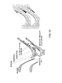
- the left side of Figure 13 illustrates the wake migration.
- the right side of Figure 13 illustrates that turning of the fluid in the downstream blade row causes the low-momentum fluid to accumulate near the suction side of the airfoil, while the higher momentum fluid outside of the wake moves toward the pressure side of the adjacent airfoil. Since the wake fluid is cooler compared to the fluid outside of the wake, the thermal segregation occurs in the passage of the downstream airfoil row where the coolant in the incoming wake cannot reach the pressure side. As a result, the pressure side of the downstream airfoil is hotter than the adjacent suction side, which may cause overheating of the pressure side.
- the wake of an upstream airfoil also introduces a secondary flow, which is often referred to as "slip" velocity, or “negative” jet if the wake has a lower velocity than surrounding flow, or “positive” jet if the wake has a higher velocity than surrounding flow.
- a velocity triangle illustrated in Figure 14 depicts the negative and positive jets. Kerrebrock, J.L. and Mikolajczak, A. A., 1970, "Intra-Stator Transport of Rotor Wakes and Its Effect on Compressor Performance", ASME J. Eng.
- Figure 1 is a perspective diagram depicting placement and operation of fluidic injection elements 10 near to but not in the trailing edge 12 of a turbine blade 14 that is known in the prior art to enhance mixing of a wake following the trailing edge 12 of the turbine blade 14.
- At least one fluidic-generated vortex 16 operates to enhance mixing of a wake 22 following the trailing edge 12 of the turbine blade 14.
- the fluidic-generated vortex 16 is generated via one or more fluidic injection elements 24 integrated near the trailing edge 12 of the turbine blade 14.
- Each fluidic injection element 24 is is configured to inject a fluid 26 such as a stream of air into a trailing edge region of the turbine blade 14 to enhance mixing out of the wakes behind the trailing edge 12 of the turbine blade 14.
- the enhanced mixing out of the wakes results in a wider wake 22.
- FIG 2 illustrates a typical turbine blade 30 having an rounded style trailing edge cooling scheme that is known in the prior art, viewed in a top-down perspective in which shaded areas 32 are metal and hollow areas 34 are coolant flow pathways.
- Turbine blade 30 comprises a trailing edge slot 36 with straight inner walls.
- Figure 3 illustrates a bleed slot trailing edge cooling scheme having a thinner trailing edge comprising a trailing edge slot with straight inner walls 38.
- FIG. 16 illustrates the mixing of velocity wakes and thermal wakes in a single sketch.
- WVR Wake Velocity Ratio
- WTR Wake Temperature Ratio
- a high pressure turbine blade or vane comprises a substantially arcuate trailing edge including one or more fluid injection structures disposed therein and configured to reduce aerodynamic losses due to wake and/or shock interactions and further configured to reduce thermal wake segregation effects to a desired level.
- a high pressure turbine (HPT) blade or vane comprises a crenulated trailing edge comprising one or more chevrons disposed on the pressure side, the suction side, or both the pressure side and suction side of the trailing edge and configured to enhance mixing out of wakes generated via the HPT blade or vane, such that aerodynamic losses due to corresponding wake and/or shock interactions are reduced to a desired level, and further such that corresponding thermal wake segregation effects are reduced to a desired level.
- HPT high pressure turbine
- a high pressure turbine (HPT) blade or vane comprises a crenulated trailing edge including one or more fluid injection structures disposed therein and configured to inject a fluid into a desired trailing edge region, wherein the injected fluid interacts with a crenulated trailing edge passage fluid flow to create a streamwise vorticity from the interaction of the injected fluid and the passage fluid flow to enhance mixing out of wakes generated via the HPT blade or vane such that aerodynamic losses due to wake and/or shock interactions are reduced to a desired level, and further such that thermal wake segregation effects are reduced to a desired level.
- HPT high pressure turbine
- a high pressure turbine (HPT) wake mixing system comprises a pre-existing HPT blade or vane comprising one or more cooling holes disposed therein outside the trailing edge of the HPT blade or vane, wherein the pre-existing HPT blade or vane is re-configured with one or more geometric elements such that fluid injected from the one or more cooling holes is manipulated via the one or more geometric elements to reduce aerodynamic losses due to wake and shock interactions and further to reduce thermal wake segregation effects to a desired level.
- a high pressure turbine (HPT) wake mixing system comprises a pre-existing HPT blade or vane comprising a substantially arcuate trailing edge, and further comprising one or more cooling slots or holes disposed therein, wherein the pre-existing HPT blade or vane is re-configured with one or more fluid injection elements disposed in the substantially arcuate trailing edge such that fluid injected from the one or more fluid injection elements interacts with fluid flowing through the one or more cooling slots or holes to reduce aerodynamic losses due to wake and shock interactions and further to reduce thermal wake segregation effects to a desired level.
- HPT high pressure turbine
- cooling hole wake mixing elements are disposed in a substantially arcuate thick trailing edge of a high pressure turbine (HPT) blade or vane to provide a trailing edge wake mixing scheme.
- HPT high pressure turbine
- these embodiments advantageously inject fluid at pitch and/or yaw angles to the main flow path to generate the desired streamwise vortices described in further detail herein.
- chevron trailing edges are provided on the pressure side, suction side, or both the pressure side and suction side of a high pressure turbine blade or vane to provide a pressure side bleed slot trailing edge wake mixing scheme.
- fluid injection elements/structures such as those depicted in Figures 10-12 and 21-22 described in further detail herein, are placed to inject fluid at predetermined angles to the corresponding turbine blade wall so as to interact with a crenulated trailing edge slot wall (such as depicted in Figures 4-8 ) passage flow and create streamwise vorticity from the interaction of this injected flow and the crenulated slot passage flow.
- the streamwise vorticity generation and strength is tailored to interact with a corresponding wake, such as, but not limited to, a trailing edge wake, and cause it to mix out, thus reducing its velocity defect by the time it interacts with downstream traveling shocks and engine components.
- fluidic creation of vorticity suitable for realizing the principles described herein is achieved using steady blowing.
- Another embodiment may employ pulsatory blowing.
- Yet another embodiment employs both steady blowing and pulsatory blowing to achieve the desired streamwise vorticity.
- Some embodiments may further employ geometric features that enhance the creation of such vorticity. Geometric features are based upon the desired application, and may include, without limitation, holes, slots and various geometric combinations thereof.
- a pair of injection holes may for example, be tailored in terms of size, and orientation of injection to create the desired or requisite features including, without limitation, strength, persistence, and frequency (if unsteady blowing is employed).
- One embodiment for fluidic creation of vorticity suitable for realizing the principles described herein is achieved by modifying holes and/or slots already employed for active cooling of HPT and/or LPT turbine blade surfaces to achieve the desired streamwise vorticity.
- Such an embodiment utilizes existing cooling infrastructures, requiring minimal re-engineering to achieve the desired vorticity.
- Means for promoting wake mixing according to the principles described herein are not limited to simple trailing edge direction ejections. They may be extended to work with additional geometrical features that cause formation of local vortices to enhance wake mixing. These features may include, without limitation, crenulated trailing edges such as depicted in Figures 4-8 .
- Figure 4 illustrates a trailing edge slot 40 for a HPT turbine blade or vane 42 in which one of the inner slot walls 44 is crenulated according to one embodiment of the invention.
- Figure 5 is an end view of the turbine blade or vane 42 depicted in Figure 4 according to one embodiment.
- Figure 6 is an end view of the turbine blade or vane 42 depicted in Figure 4 according to another embodiment.
- the crenulated inner slot wall 44 operates to further enhance mixing of a wake generated via the turbine blade 42 beyond that achievable using 1) only fluidic injection elements/structures or cooling holes, 2) using only changes in blade/vane planform or camber, or 3) using fluidic injection elements/structures in combination with trailing edge slots with straight inner walls.
- FIG 7 is a perspective view illustrating a crenulated trailing edge 50 for a high pressure turbine (HPT) blade or vane according to another embodiment.
- Figure 8 illustrates a chevron trailing edge 60 for a high pressure turbine blade or vane according to yet another embodiment.
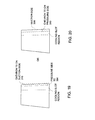
- Chevrons 310 are defined as triangular serration planform changes that are employed on either the pressure side 304 such as depicted in Figure 20 , suction side such as depicted in Figure 19 , or both the pressure side and suction side of a high pressure turbine blade or vane such as, without limitation, the blade depicted in Figure 3 .
- Gas turbine blades/vanes 300 such as that depicted in Figures 21 and 22 having sharp pressure side and suction side trailing edges 304, 306 and pressure side cooling slots 302, for example, may be configured such that either the lower lip or the upper lip or both sides could employ chevrons or crenulated surfaces or combinations of both in which cooling passages 302 are aligned in such a way with the geometrical feature(s) such that the production of streamwise vorticity is maximized.
- Figure 21 is a side view illustrating a trailing edge portion of a turbine blade/vane 300 suitable for use in aircraft engine applications where the trailing edge 304, 306 is thinner than that used for power generation machines.
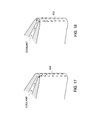
- a streamwise vortex is thus created via one or more fluid injection elements 400, 402 disposed on the trailing edge (TE) such as depicted in Figures 17 and 18 that illustrate fluid injection slots 400 and fluid injection holes 402 respectively, and that may be integrated with one or more geometrical features of a high pressure turbine (HPT) or low pressure turbine (LPT) blade such that local vortices enhance wake mixing beyond that achievable using known techniques.
- HPT high pressure turbine
- LPT low pressure turbine
- each fluid injection element is configured to inject a fluid such as a stream of air into the trailing edge region of a corresponding HPT or LPT turbine blade to interact with a corresponding passage fluid flow and create a streamwise vorticity from the interaction of the injected fluid flow and the passage fluid flow, to enhance mixing out of the wakes behind the trailing edge of the (HP or LP) turbine blade.
- a fluid such as a stream of air into the trailing edge region of a corresponding HPT or LPT turbine blade to interact with a corresponding passage fluid flow and create a streamwise vorticity from the interaction of the injected fluid flow and the passage fluid flow
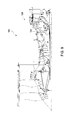
- Figure 9 is a simplified schematic diagram illustrating a cross sectional view of a portion of a gas turbine engine 100 that may employ various embodiments of the invention.
- Gas turbine engine 100 can be seen to include a HPT 124 interacting with a corresponding LPT 128.
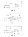
- Figure 10 is a cross-sectional view depicting placement and operation of fluid injection elements 200 in the substantially arcuate trailing edge 12 of a HP or LP turbine blade 14 to reduce aerodynamic losses due to wake and/or shock interactions and further to reduce thermal wake segregation effects to a desirable level according to one embodiment of the invention.
- Fluid injection elements 200 comprise a pair of fluid injection holes 202, 204 configured to inject a desired fluid 26 such as air according to the principles described herein into both pressure and suction sides of the trailing edge of blade 14.
- Figure 11 is a cross-sectional view depicting placement and operation of one or more fluid injection elements 210 in the substantially arcuate trailing edge 12 of a HP or LP turbine blade 14 to reduce aerodynamic losses due to wake and/or shock interactions and further to reduce thermal wake segregation effects to a desirable level according to another embodiment of the invention.
- a fluid injection hole 212 that forms one portion of fluid injection element 210 is configured to inject a desired fluid 26 such as air according to the principles described herein into the tip portion of the blade 14 trailing edge 12.
- Figure 12 is a cross-sectional view depicting placement and operation of one or more fluid injection elements 220 in the substantially arcuate trailing edge 12 of a HP or LP turbine blade 14 to reduce aerodynamic losses due to wake and/or shock interactions and further to reduce thermal wake segregation effects to a desirable level according to another embodiment of the invention.
- a fluid injection hole 222 that forms one portion of fluid injection element 220 is configured to inject a desired fluid 26 such as air according to the principles described herein into a pressure side or suction side of the trailing edge 12 of the blade 14.
- the embodiments described herein advantageously reduce aerodynamic losses due to wake and shock interactions. These include steady and unsteady losses for transonic vanes/blades and unsteady losses due to wake interactions when blades/vanes are subsonic.
- the embodiments described herein further advantageously reduce unsteady thermal wake segregation effects that lead to unexpected her-up of endwalls of downstream blades caused by cold wakes and hot post-combustion gases leading to the thermal wake migration effect.
- the principles described herein can easily be employed to selectively mix wakes generated via a HP or LP gas turbine blade or vane in which the selection is based upon the type of HPT and/or LPT blade or vane, and such that corresponding aerodynamic losses due to wake and/or shock interactions are reduced to a desirable level, and further such that corresponding thermal wake segregation effects are reduced to a desirable level based on one or more downstream turbine blade or vane aerodynamic and thermal requirements.
Landscapes
- Engineering & Computer Science (AREA)
- Physics & Mathematics (AREA)
- Fluid Mechanics (AREA)
- Mechanical Engineering (AREA)
- General Engineering & Computer Science (AREA)
- Turbine Rotor Nozzle Sealing (AREA)
Abstract
Description
- The invention relates generally to gas turbine engines and more particularly to a system and method for re-tasking, redesigning and/or manipulating the use of coolant injection holes to enhance the mixing of a gas turbine blade or vane wake to reduce HPT/LPT (high pressure turbine/low pressure turbine) interaction losses and improve the thermal durability of the turbine.
- Turbine blade/vane wakes interact with turbine blade/vane shock wave systems and, if not fully mixed, with downstream blades/vanes. This process generates higher losses, and often requires extra axial spacing between the HPT and LPT to fully mix the wakes. Besides the aero-performance benefit of wake mixing, its benefit can also be extended to include the thermal effect. The wakes coming off of the film-cooled turbine vanes and blades have temperature deficits in addition to the pressure deficit. The low-momentum fluid in the wake of an airfoil (vane or blade) migrates downstream, and is ingested and turned by the downstream airfoil. The left side of
Figure 13 illustrates the wake migration. The right side ofFigure 13 illustrates that turning of the fluid in the downstream blade row causes the low-momentum fluid to accumulate near the suction side of the airfoil, while the higher momentum fluid outside of the wake moves toward the pressure side of the adjacent airfoil. Since the wake fluid is cooler compared to the fluid outside of the wake, the thermal segregation occurs in the passage of the downstream airfoil row where the coolant in the incoming wake cannot reach the pressure side. As a result, the pressure side of the downstream airfoil is hotter than the adjacent suction side, which may cause overheating of the pressure side. - Further, the wake of an upstream airfoil also introduces a secondary flow, which is often referred to as "slip" velocity, or "negative" jet if the wake has a lower velocity than surrounding flow, or "positive" jet if the wake has a higher velocity than surrounding flow. A velocity triangle illustrated in
Figure 14 depicts the negative and positive jets. Kerrebrock, J.L. and Mikolajczak, A. A., 1970, "Intra-Stator Transport of Rotor Wakes and Its Effect on Compressor Performance", ASME J. Eng. Power, Vol 92, pp.359-370, describes that even if the fluid temperature is the same everywhere, as the flow migrates to the downstream, this secondary flow causes the transport of the fluid across the airfoil passage, which in turn causes a temperature gradient across the passage. -
Figure 1 is a perspective diagram depicting placement and operation offluidic injection elements 10 near to but not in thetrailing edge 12 of aturbine blade 14 that is known in the prior art to enhance mixing of a wake following thetrailing edge 12 of theturbine blade 14. At least one fluidic-generatedvortex 16 operates to enhance mixing of awake 22 following thetrailing edge 12 of theturbine blade 14. The fluidic-generatedvortex 16 is generated via one or more fluidic injection elements 24 integrated near thetrailing edge 12 of theturbine blade 14. Each fluidic injection element 24 is is configured to inject afluid 26 such as a stream of air into a trailing edge region of theturbine blade 14 to enhance mixing out of the wakes behind thetrailing edge 12 of theturbine blade 14. The enhanced mixing out of the wakes results in awider wake 22. -
Figure 2 illustrates atypical turbine blade 30 having an rounded style trailing edge cooling scheme that is known in the prior art, viewed in a top-down perspective in whichshaded areas 32 are metal andhollow areas 34 are coolant flow pathways.Turbine blade 30 comprises atrailing edge slot 36 with straight inner walls.Figure 3 illustrates a bleed slot trailing edge cooling scheme having a thinner trailing edge comprising a trailing edge slot with straightinner walls 38. - Although fluidic injection elements/cooling holes and slots have been employed in the prior art to provide both aerodynamic performance benefits and cooling of turbine blades/vanes, such techniques have not yet successfully addressed aerodynamic losses resulting from wake and shock interactions, both steady and unsteady for transonic vanes/blades as well as unsteady losses due to wake interactions when blades/vanes are subsonic. Further, high pressure turbines where the vanes are heavily cooled to ensure durability in high temperature environments, e.g. film and trailing edge cooling, can result in unsteady thermal wake segregation effects that lead to the unexpected heat-up of endwalls, e.g. platforms and blade/vane tips, of downstream blades/vanes. Large temperature gradients are caused by the cold wakes in combination with hot post-combustion gases, which leads to a thermal wake migration effect.
- In view of the foregoing, it would be advantageous to provide a system and method to reduce both the total pressure gradient and the total temperature gradient. The system and method should re-condition the flow that goes into the downstream airfoil row via mixing of the thermal wakes of an upstream blade row to reduce the thermal load of the adjacent downstream blade row by reducing the thermal segregation effect within the downstream blade row.
Figure 16 illustrates the mixing of velocity wakes and thermal wakes in a single sketch. Two parameters are introduced to measure the wake mixing. The first is Wake Velocity Ratio (WVR), which is defined herein as a ratio of velocity integral in the wake region and that in the free-flow region. The other parameter is Wake Temperature Ratio (WTR), which is defined as a ratio of mass-weighed temperature integral in the wake region and that in the free-flow region. - Briefly, in accordance with one embodiment, a high pressure turbine blade or vane comprises a substantially arcuate trailing edge including one or more fluid injection structures disposed therein and configured to reduce aerodynamic losses due to wake and/or shock interactions and further configured to reduce thermal wake segregation effects to a desired level.
- According to another embodiment, a high pressure turbine (HPT) blade or vane comprises a crenulated trailing edge comprising one or more chevrons disposed on the pressure side, the suction side, or both the pressure side and suction side of the trailing edge and configured to enhance mixing out of wakes generated via the HPT blade or vane, such that aerodynamic losses due to corresponding wake and/or shock interactions are reduced to a desired level, and further such that corresponding thermal wake segregation effects are reduced to a desired level.
- According to yet another embodiment, a high pressure turbine (HPT) blade or vane comprises a crenulated trailing edge including one or more fluid injection structures disposed therein and configured to inject a fluid into a desired trailing edge region, wherein the injected fluid interacts with a crenulated trailing edge passage fluid flow to create a streamwise vorticity from the interaction of the injected fluid and the passage fluid flow to enhance mixing out of wakes generated via the HPT blade or vane such that aerodynamic losses due to wake and/or shock interactions are reduced to a desired level, and further such that thermal wake segregation effects are reduced to a desired level.
- According to still another embodiment, a high pressure turbine (HPT) wake mixing system comprises a pre-existing HPT blade or vane comprising one or more cooling holes disposed therein outside the trailing edge of the HPT blade or vane, wherein the pre-existing HPT blade or vane is re-configured with one or more geometric elements such that fluid injected from the one or more cooling holes is manipulated via the one or more geometric elements to reduce aerodynamic losses due to wake and shock interactions and further to reduce thermal wake segregation effects to a desired level.
- According to still another embodiment, a high pressure turbine (HPT) wake mixing system comprises a pre-existing HPT blade or vane comprising a substantially arcuate trailing edge, and further comprising one or more cooling slots or holes disposed therein, wherein the pre-existing HPT blade or vane is re-configured with one or more fluid injection elements disposed in the substantially arcuate trailing edge such that fluid injected from the one or more fluid injection elements interacts with fluid flowing through the one or more cooling slots or holes to reduce aerodynamic losses due to wake and shock interactions and further to reduce thermal wake segregation effects to a desired level.
- These and other features, aspects, and advantages of the present invention will become better understood when the following detailed description is read with reference to the accompanying drawings in which like characters represent like parts throughout the drawings, wherein:
-
Figure 1 is a perspective diagram depicting placement and operation of fluidic injection elements near but not in the trailing edge of a turbine blade that is known in the prior art to enhance mixing of a wake following the trailing edge of the turbine blade; -
Figure 2 illustrates a known turbine blade comprising an rounded trailing edge viewed in a top-down perspective in which shaded areas are metal and hollow areas are coolant flow pathways; -
Figure 3 illustrates a known thick trailing edge cooling scheme comprising a trailing edge slot with straight inner walls, usually used in power generation turbines; -
Figure 4 illustrates a trailing edge slot for a turbine blade or vane in which one of the inner slot walls is crenulated according to one embodiment of the invention; -
Figure 5 is an end view of the turbine blade or vane depicted inFigure 4 according to one embodiment; -
Figure 6 is an end view of the turbine blade or vane depicted inFigure 4 according to another embodiment; -
Figure 7 is a perspective view illustrating a crenulated trailing edge for a turbine blade or vane according to one embodiment; -
Figure 8 illustrates a chevron trailing edge for a high pressure turbine blade or vane according to one embodiment; -
Figure 9 is a simplified schematic diagram illustrating a gas turbine engine that may employ various embodiments of the invention; -
Figure 10 is a cross-sectional view depicting placement and operation of fluidic injection elements in the trailing edge of a turbine blade to reduce aerodynamic losses due to wake and/or shock interactions and to reduce thermal wake segregation effects to a desirable level according to one embodiment of the invention; -
Figure 11 is a cross-sectional view depicting placement and operation of fluidic injection elements in the trailing edge of a turbine blade to reduce aerodynamic losses due to wake and/or shock interactions and to reduce thermal wake segregation effects to a desirable level according to another embodiment of the invention; -
Figure 12 is a cross-sectional view depicting placement and operation of fluidic injection elements in the trailing edge of a turbine blade to reduce aerodynamic losses due to wake and/or shock interactions and to reduce thermal wake segregation effects to a desirable level according to another embodiment of the invention; -
Figure 13 illustrates wake migration and turning of a fluid in a downstream blade row causing low-momentum fluid to accumulate near the suction side of the airfoil, while the higher momentum fluid outside of the wake moves toward the pressure side of the adjacent airfoil according to one embodiment; -
Figure 14 illustrates a velocity triangle showing the wake of an upstream airfoil introducing a secondary flow, which is often referred to as "slip" velocity, or "negative" jet if the wake has a lower velocity than surrounding flow, or "positive" jet if the wake has a higher velocity than surrounding flow; -
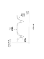
Figure 15 illustrates the correlation of the wake temperature ratio and the airfoil surface temperature difference based on mixing of the thermal wakes of an upstream blade row to reduce the thermal load of the adjacent downstream blade row by reducing the thermal segregation effect within the downstream blade row according to one embodiment; -
Figure 16 illustrates the mixing of velocity wakes and thermal wakes in a single sketch; -
Figure 17 illustrates fluid injection slots disposed in the trailing edge of a turbine blade or vane according to one embodiment; -
Figure 18 illustrates fluid injection holes disposed in the trailing edge of a turbine blade or vane according to one embodiment; -
Figure 19 illustrates a chevron trailing edge on the suction side of a turbine blade or vane according to one embodiment; -
Figure 20 illustrates a chevron trailing edge on the pressure side of a turbine blade or vane according to one embodiment; -
Figure 21 illustrates cooling slots on the pressure side trailing edge of a turbine blade or vane according to one embodiment; and -
Figure 22 is a cross-sectional top view of the turbine blade or vane depicted inFigure 21 . - While the above-identified drawing figures set forth alternative embodiments, other embodiments of the present invention are also contemplated, as noted in the discussion. In all cases, this disclosure presents illustrated embodiments of the present invention by way of representation and not limitation. Numerous other modifications and embodiments can be devised by those skilled in the art which fall within the scope and spirit of the principles of this invention.
- According to particular embodiments such as those depicted in
Figures 10-12 and17-18 described in further detail herein, cooling hole wake mixing elements are disposed in a substantially arcuate thick trailing edge of a high pressure turbine (HPT) blade or vane to provide a trailing edge wake mixing scheme. Unlike conventional trailing edge wake mixing schemes that inject fluid parallel to the main flow path, these embodiments advantageously inject fluid at pitch and/or yaw angles to the main flow path to generate the desired streamwise vortices described in further detail herein. - According to other embodiments such as those depicted in
Figures 4-8 and19-20 described in further detail herein, chevron trailing edges are provided on the pressure side, suction side, or both the pressure side and suction side of a high pressure turbine blade or vane to provide a pressure side bleed slot trailing edge wake mixing scheme. - According to yet other embodiments, fluid injection elements/structures such as those depicted in
Figures 10-12 and21-22 described in further detail herein, are placed to inject fluid at predetermined angles to the corresponding turbine blade wall so as to interact with a crenulated trailing edge slot wall (such as depicted inFigures 4-8 ) passage flow and create streamwise vorticity from the interaction of this injected flow and the crenulated slot passage flow. The streamwise vorticity generation and strength is tailored to interact with a corresponding wake, such as, but not limited to, a trailing edge wake, and cause it to mix out, thus reducing its velocity defect by the time it interacts with downstream traveling shocks and engine components. - These fluidic techniques for generating streamwise vorticity function to enhance wake mixing and result in fast dissipation of wakes. Fast dissipation of the wakes coming off high pressure turbine blades/
vanes 14 reduces the aerodynamic losses that would otherwise result when these wakes interact with neighboring low pressure turbine (LPT) blades/vanes and their corresponding flow structures. - According to one embodiment, fluidic creation of vorticity suitable for realizing the principles described herein is achieved using steady blowing. Another embodiment may employ pulsatory blowing. Yet another embodiment employs both steady blowing and pulsatory blowing to achieve the desired streamwise vorticity. Some embodiments may further employ geometric features that enhance the creation of such vorticity. Geometric features are based upon the desired application, and may include, without limitation, holes, slots and various geometric combinations thereof. A pair of injection holes, may for example, be tailored in terms of size, and orientation of injection to create the desired or requisite features including, without limitation, strength, persistence, and frequency (if unsteady blowing is employed).
- One embodiment for fluidic creation of vorticity suitable for realizing the principles described herein is achieved by modifying holes and/or slots already employed for active cooling of HPT and/or LPT turbine blade surfaces to achieve the desired streamwise vorticity. Such an embodiment utilizes existing cooling infrastructures, requiring minimal re-engineering to achieve the desired vorticity.
- Means for promoting wake mixing according to the principles described herein are not limited to simple trailing edge direction ejections. They may be extended to work with additional geometrical features that cause formation of local vortices to enhance wake mixing. These features may include, without limitation, crenulated trailing edges such as depicted in
Figures 4-8 . -
Figure 4 illustrates a trailingedge slot 40 for a HPT turbine blade orvane 42 in which one of theinner slot walls 44 is crenulated according to one embodiment of the invention.Figure 5 is an end view of the turbine blade orvane 42 depicted inFigure 4 according to one embodiment.Figure 6 is an end view of the turbine blade orvane 42 depicted inFigure 4 according to another embodiment. The crenulatedinner slot wall 44 operates to further enhance mixing of a wake generated via theturbine blade 42 beyond that achievable using 1) only fluidic injection elements/structures or cooling holes, 2) using only changes in blade/vane planform or camber, or 3) using fluidic injection elements/structures in combination with trailing edge slots with straight inner walls. -
Figure 7 is a perspective view illustrating acrenulated trailing edge 50 for a high pressure turbine (HPT) blade or vane according to another embodiment.Figure 8 illustrates achevron trailing edge 60 for a high pressure turbine blade or vane according to yet another embodiment.Chevrons 310, as used herein, are defined as triangular serration planform changes that are employed on either thepressure side 304 such as depicted inFigure 20 , suction side such as depicted inFigure 19 , or both the pressure side and suction side of a high pressure turbine blade or vane such as, without limitation, the blade depicted inFigure 3 . - Gas turbine blades/
vanes 300 such as that depicted inFigures 21 and 22 having sharp pressure side and suctionside trailing edges side cooling slots 302, for example, may be configured such that either the lower lip or the upper lip or both sides could employ chevrons or crenulated surfaces or combinations of both in whichcooling passages 302 are aligned in such a way with the geometrical feature(s) such that the production of streamwise vorticity is maximized.Figure 21 is a side view illustrating a trailing edge portion of a turbine blade/vane 300 suitable for use in aircraft engine applications where the trailingedge - A streamwise vortex is thus created via one or more
fluid injection elements Figures 17 and 18 that illustratefluid injection slots 400 and fluid injection holes 402 respectively, and that may be integrated with one or more geometrical features of a high pressure turbine (HPT) or low pressure turbine (LPT) blade such that local vortices enhance wake mixing beyond that achievable using known techniques. According to one embodiment, each fluid injection element is configured to inject a fluid such as a stream of air into the trailing edge region of a corresponding HPT or LPT turbine blade to interact with a corresponding passage fluid flow and create a streamwise vorticity from the interaction of the injected fluid flow and the passage fluid flow, to enhance mixing out of the wakes behind the trailing edge of the (HP or LP) turbine blade. The enhanced mixing out of the wakes behind the trailing edge of the turbine blade reduces HPT/LPT interaction losses and/or enables shortening of the axial gap between the HPT and LPT components in a gas turbine engine. - More specifically, with induction of vortices, system and method embodiments have been described to reduce both the total pressure gradient and the total temperature gradient. This re-conditions the flow that goes into the downstream airfoil row. Mixing of the thermal wakes of an upstream blade row is beneficial to reduce the thermal load of the adjacent downstream blade row by reducing the thermal segregation effect within the downstream blade row. This effect is illustrated in more detail by the graph shown in
Figure 15 that depicts the correlation of the wake temperature ratio and the airfoil surface temperature difference, wherein the wake temperature ratio in the graph is defined as total temperature in the wake region divided by total temperature in the flow region that is outside of the wake. - Existing technology employed for aerodynamic performance can be modified to implement the principles described herein, recognizing that a tradeoff will be required between aerodynamic performance and system/thermal requirements. Thus, existing technology employed for aerodynamic performance can be modified to implement the principles described herein so long as both aerodynamic performance and system/thermal requirements can simultaneously be achieved.
-
Figure 9 is a simplified schematic diagram illustrating a cross sectional view of a portion of agas turbine engine 100 that may employ various embodiments of the invention.Gas turbine engine 100 can be seen to include aHPT 124 interacting with acorresponding LPT 128. -
Figure 10 is a cross-sectional view depicting placement and operation offluid injection elements 200 in the substantially arcuate trailingedge 12 of a HP orLP turbine blade 14 to reduce aerodynamic losses due to wake and/or shock interactions and further to reduce thermal wake segregation effects to a desirable level according to one embodiment of the invention.Fluid injection elements 200 comprise a pair of fluid injection holes 202, 204 configured to inject a desiredfluid 26 such as air according to the principles described herein into both pressure and suction sides of the trailing edge ofblade 14. -
Figure 11 is a cross-sectional view depicting placement and operation of one or morefluid injection elements 210 in the substantially arcuate trailingedge 12 of a HP orLP turbine blade 14 to reduce aerodynamic losses due to wake and/or shock interactions and further to reduce thermal wake segregation effects to a desirable level according to another embodiment of the invention. Afluid injection hole 212 that forms one portion offluid injection element 210 is configured to inject a desiredfluid 26 such as air according to the principles described herein into the tip portion of theblade 14 trailingedge 12. -
Figure 12 is a cross-sectional view depicting placement and operation of one or morefluid injection elements 220 in the substantially arcuate trailingedge 12 of a HP orLP turbine blade 14 to reduce aerodynamic losses due to wake and/or shock interactions and further to reduce thermal wake segregation effects to a desirable level according to another embodiment of the invention. Afluid injection hole 222 that forms one portion offluid injection element 220 is configured to inject a desiredfluid 26 such as air according to the principles described herein into a pressure side or suction side of the trailingedge 12 of theblade 14. - The embodiments described herein advantageously reduce aerodynamic losses due to wake and shock interactions. These include steady and unsteady losses for transonic vanes/blades and unsteady losses due to wake interactions when blades/vanes are subsonic. The embodiments described herein further advantageously reduce unsteady thermal wake segregation effects that lead to unexpected her-up of endwalls of downstream blades caused by cold wakes and hot post-combustion gases leading to the thermal wake migration effect.
- The principles described herein can easily be employed to selectively mix wakes generated via a HP or LP gas turbine blade or vane in which the selection is based upon the type of HPT and/or LPT blade or vane, and such that corresponding aerodynamic losses due to wake and/or shock interactions are reduced to a desirable level, and further such that corresponding thermal wake segregation effects are reduced to a desirable level based on one or more downstream turbine blade or vane aerodynamic and thermal requirements.
- While only certain features of the invention have been illustrated and described herein, many modifications and changes will occur to those skilled in the art. It is, therefore, to be understood that the appended claims are intended to cover all such modifications and changes as fall within the true spirit of the invention.
- For completeness, various aspects of the invention are now set out in the following numbered clauses:
- 1. A high pressure turbine (HPT) blade or vane comprising:
- a substantially arcuate trailing edge comprising an arrangement of trailing edge cooling holes configured as fluid injection elements to inject fluid there from at one or more angles to the main flow to create vorticity that mixes out the wake, such that aerodynamic losses due to wake and shock interactions are reduced to a desired level, and further such that thermal wake segregation effects are reduced to a desired level.
- 2. The HPT blade or vane according to clause 1, wherein at least one fluid injection element is configured to inject fluid on the pressure side of the trailing edge.
- 3. The HPT blade or vane according to clause 1, wherein at least one fluid injection element is configured to inject fluid on the suction side of the trailing edge.
- 4. The HPT blade or vane according to clause 1, wherein at least one fluid injection element is configured to inject fluid on the pressure side of the trailing edge and at least one different fluid injection element is configured to inject fluid on the suction side of the trailing edge.
- 5. The HPT blade or vane according to clause 1, wherein one or more fluid njection elements are configured to inject the fluid at a predetermined fixed rate of fluid flow simultaneously with pulsatory injection of fluid via a different injection element.
- 6. The HPT blade or vane according to clause 1, wherein one or more fluid injection elements comprise a fluid injection hole.
- 7. The HPT blade or vane according to clause 1, wherein one or more fluid injection elements comprise a fluid injection slot.
- 8. The HPT blade or vane according to clause 1, wherein the one or more fluid injection elements comprise at least one fluid injection hole and at least one fluid injection slot.
- 9. The HPT blade or vane according to clause 1, wherein each injection element is further configured in terms of size and orientation relative to its corresponding turbine blade or vane, such that the one or more injection elements generate streamwise vorticity with properties comprising at least one of desired vorticity strength, desired vorticity persistence, and desired vorticity frequency.
- 10. The HPT blade or vane according to clause 1, further comprising one or more turbine blade or vane geometric elements, wherein the one or more geometric elements in combination with the one or more fluid injection elements are together configured to mix the wakes generated via the HPT turbine blade or vane.
- 11. The HPT blade or vane according to
clause 10, wherein the one or more geometric elements comprise one or more fluidic passages. - 12. The HPT turbine blade or vane according to
claim 10, wherein the one or more geometric elements are selected from a crenulated trailing edge, a chevron trailing edge, a trailing edge cooling slot, and combinations thereof. - 13. The HPT blade or vane according to
clause 10, wherein the one or more geometric elements comprise a trailing edge slot, wherein at least one inner wall of the slot is crenulated in a spanwise direction of the slot. - 14. The HPT blade or vane according to clause 1, wherein one or more fluid injection elements are further configured to inject a fluid in at least one desired trailing edge region to interact with at least one corresponding passage fluid flow and create a streamwise vorticity from the interaction of the injected fluid flow and the passage fluid flow.
- 15. The gas turbine blade or vane according to clause 1, wherein one or more fluid injection elements are operational to selectively mix wakes generated via the HPT blade or vane, the selection based on the type of gas turbine blade or vane.
- 16. The HPT blade or vane according to clause 1, wherein one or more fluid injection elements are further configured to inject a desired fluid selected from air, a desired gas other than air, and combinations thereof.
- 17. A high pressure turbine (HPT) blade or vane comprising:
- a crenulated trailing edge comprising one or more chevrons disposed on the pressure side, suction side, or both the pressure side and suction side of the HPT blade or vane and configured to enhance mixing out of wakes generated via the HPT blade or vane,
- such that aerodynamic losses due to corresponding wake and shock interactions are reduced to a desired level, and further such that corresponding thermal wake segregation effects are reduced to a desired level.
- 18. The HPT blade or vane according to clause 17, wherein the crenulated trailing edge comprises a wavy trailing edge.
- 19. The HPT blade or vane according to clause 17, wherein the crenulated trailing edge comprises a chevron trailing edge.
- 20. The HPT blade or vane according to clause 17, wherein the crenulated trailing edge comprises a cooling slot.
- 21. The HPT blade or vane according to clause 20, wherein at least one inner wall of the slot is crenulated in a spanwise direction of the slot.
- 22. The HPT blade or vane according to clause 17, wherein the crenulated trailing edge is configured to selectively mix wakes generated via the HPT blade or vane, the selection based on the type of HPT blade or vane.
- 23. The HPT blade or vane according to clause 17, further comprising one or more fluid injection structures configured to inject a desired fluid selected from air, a desired gas other than air, and combinations thereof into a desired trailing edge region such that the injected fluid interacts with a passage fluid flow generated via the crenulated trailing edge to reduce aerodynamic losses due to wake and shock interactions and thermal wake segregation effects to a desired level.
- 24. A high pressure turbine (HPT) blade or vane comprising:
- at least one crenulated passage; and
- at least one fluid injection element disposed in at least one wall of at least one crenulated passage and configured to inject a fluid there from, wherein the injected fluid interacts with a corresponding crenulated passage fluid flow to create a streamwise vorticity from the interaction of the injected fluid and the passage fluid flow to enhance mixing out of wakes generated via the HPT blade or vane such that aerodynamic losses due to wake and shock interactions are reduced to a desired level, and further such that thermal wake segregation effects are reduced to a desired level.
- 25. The HPT blade or vane according to clause 24, wherein one or more fluid injection elements are configured to inject the fluid at a predetermined fixed rate of fluid flow simultaneously with pulsatory injection of fluid via a different injection element.
- 26. The HPT blade or vane according to clause 24, wherein one or more fluid injection elements comprise a fluid injection hole.
- 27. The HPT blade or vane according to clause 24, wherein one or more fluid injection elements comprise a fluid injection slot.
- 28. The HPT blade or vane according to clause 24, wherein the one or more fluid injection elements comprise at least one fluid injection hole and at least one fluid injection slot.
- 29. The HPT blade or vane according to clause 24, wherein each injection element is further configured in terms of size and orientation relative to its corresponding turbine blade or vane, such that the one or more injection elements generate streamwise vorticity with properties comprising at least one of desired vorticity strength, desired vorticity persistence, and desired vorticity frequency.
- 30. A high pressure turbine (HPT) wake mixing system comprising:
- a pre-existing HPT blade or vane comprising one or more cooling holes disposed therein outside the trailing edge of the HPT blade or vane, wherein the pre-existing HPT blade or vane is re-configured with one or more geometric elements such that fluid injected from the one or more cooling holes is manipulated via the one or more geometric elements to reduce aerodynamic losses due to wake and shock interactions and further to reduce thermal wake segregation effects to a desired level.
- 31. A high pressure turbine (HPT) wake mixing system comprising:
- a pre-existing HPT blade or vane comprising a substantially arcuate trailing edge,
- and further comprising one or more cooling slots disposed therein, wherein the pre-existing HPT blade or vane is re-configured with one or more fluid injection elements disposed in the substantially arcuate trailing edge such that fluid injected from the one or more fluid injection elements interacts with fluid flowing through the one or more cooling slots to reduce aerodynamic losses due to wake and shock interactions and further to reduce thermal wake segregation effects to a desired level.
Claims (10)
- A high pressure turbine (HPT) blade (14) or vane (14) comprising:a. a substantially arcuate trailing edge (12) comprising an arrangement of trailing edge cooling holes (202), (204) configured as fluid injection elements to inject fluid there from at one or more angles to the main flow to create vorticity that mixes out the wake, such that aerodynamic losses due to wake and shock interactions are reduced to a desired level, and further such that thermal wake segregation effects are reduced to a desired level.
- The HPT blade or vane (14) according to claim 1, wherein at least one fluid injection element (202), (204) is configured to inject fluid on the pressure side of the trailing edge (12).
- The HPT blade or vane (14) according to claim 1 or 2, wherein at least one fluid injection element (202), (204) is configured to inject fluid on the suction side of the trailing edge (12).
- The HPT blade or vane (14) according to any of the preceding claims, wherein at least one fluid injection element (202) is configured to inject fluid on the pressure side of the trailing edge (12) and at least one different fluid injection element (204) is configured to inject fluid on the suction side of the trailing edge (12).
- The HPT blade or vane (14) according to any of the preceding claims, wherein one or more fluid injection elements (202) are configured to inject the fluid at a predetermined fixed rate of fluid flow simultaneously with pulsatory injection of fluid via a different injection element (204).
- The HPT blade or vane (14) according to any of the preceding claims, wherein each injection element (202), (204) is further configured in terms of size and orientation relative to its corresponding turbine blade or vane (14), such that the one or more injection elements (202), (204) generate streamwise vorticity with properties comprising at least one of desired vorticity strength, desired vorticity persistence, and desired vorticity frequency.
- The HPT blade or vane (14) according to any of the preceding claims, further comprising one or more turbine blade or vane geometric elements (200), wherein the one or more geometric elements (200) in combination with the one or more fluid injection elements are together configured to mix the wakes generated via the HPT turbine blade or vane (14).
- The HPT blade or vane (14) according to claim 7, wherein the one or more geometric elements (200) comprise one or more fluidic passages.
- The HPT turbine blade or vane (14) according to claim 7, wherein the one or more geometric elements are selected from a crenulated trailing edge, a chevron trailing edge, a trailing edge cooling slot, and combinations thereof.
- The HPT blade or vane (14) according to claim 7, wherein the one or more geometric elements (200) comprise a trailing edge slot, wherein at least one inner wall of the slot is crenulated in a spanwise direction of the slot.
Applications Claiming Priority (1)
| Application Number | Priority Date | Filing Date | Title |
|---|---|---|---|
| US12/789,480 US8608429B2 (en) | 2010-05-28 | 2010-05-28 | System and method for enhanced turbine wake mixing via fluidic-generated vortices |
Publications (3)
| Publication Number | Publication Date |
|---|---|
| EP2390464A2 true EP2390464A2 (en) | 2011-11-30 |
| EP2390464A3 EP2390464A3 (en) | 2017-12-06 |
| EP2390464B1 EP2390464B1 (en) | 2020-08-26 |
Family
ID=44352267
Family Applications (1)
| Application Number | Title | Priority Date | Filing Date |
|---|---|---|---|
| EP11167956.9A Active EP2390464B1 (en) | 2010-05-28 | 2011-05-27 | Turbine blade with enhanced wake mixing via fluidic-generated vortices |
Country Status (4)
| Country | Link |
|---|---|
| US (1) | US8608429B2 (en) |
| EP (1) | EP2390464B1 (en) |
| JP (1) | JP5826516B2 (en) |
| CN (1) | CN102330571B (en) |
Cited By (3)
| Publication number | Priority date | Publication date | Assignee | Title |
|---|---|---|---|---|
| EP2669474A1 (en) | 2012-06-01 | 2013-12-04 | MTU Aero Engines GmbH | Transition channel for a fluid flow engine and fluid flow engine |
| EP2912278A4 (en) * | 2012-10-23 | 2015-12-23 | United Technologies Corp | REDUCING EXCITATION OF TURBINE DISPENSER FINS EQUIDISTANT |
| EP3034794A1 (en) * | 2014-12-15 | 2016-06-22 | United Technologies Corporation | Gas turbine engine component and corresponding wall |
Families Citing this family (19)
| Publication number | Priority date | Publication date | Assignee | Title |
|---|---|---|---|---|
| DE102013206207A1 (en) * | 2013-04-09 | 2014-10-09 | MTU Aero Engines AG | Airfoil for a turbomachine with trailing edge profiling, blade and integrally bladed rotor |
| US20150041590A1 (en) * | 2013-08-09 | 2015-02-12 | General Electric Company | Airfoil with a trailing edge supplement structure |
| JP6245740B2 (en) * | 2013-11-20 | 2017-12-13 | 三菱日立パワーシステムズ株式会社 | Gas turbine blade |
| US20150167979A1 (en) * | 2013-12-17 | 2015-06-18 | General Electric Company | First stage nozzle or transition nozzle configured to promote mixing of respective combustion streams downstream thereof before entry into a first stage bucket of a turbine |
| US9879547B2 (en) * | 2013-12-30 | 2018-01-30 | General Electric Company | Interior cooling circuits in turbine blades |
| US10436037B2 (en) | 2016-07-22 | 2019-10-08 | General Electric Company | Blade with parallel corrugated surfaces on inner and outer surfaces |
| US10443399B2 (en) | 2016-07-22 | 2019-10-15 | General Electric Company | Turbine vane with coupon having corrugated surface(s) |
| US10465525B2 (en) | 2016-07-22 | 2019-11-05 | General Electric Company | Blade with internal rib having corrugated surface(s) |
| US10465520B2 (en) | 2016-07-22 | 2019-11-05 | General Electric Company | Blade with corrugated outer surface(s) |
| US10450868B2 (en) | 2016-07-22 | 2019-10-22 | General Electric Company | Turbine rotor blade with coupon having corrugated surface(s) |
| JP6993687B2 (en) * | 2017-02-23 | 2022-01-13 | 国立大学法人東京農工大学 | Turbine blade cooling method |
| US20190078450A1 (en) * | 2017-09-08 | 2019-03-14 | United Technologies Corporation | Inlet guide vane having a varied trailing edge geometry |
| GB2581351A (en) * | 2019-02-13 | 2020-08-19 | Rolls Royce Plc | Blade for a gas turbine engine |
| GB2592009B (en) * | 2020-02-11 | 2022-08-24 | Gkn Aerospace Sweden Ab | Compressor blade |
| CN112523809A (en) * | 2020-11-30 | 2021-03-19 | 北京动力机械研究所 | Method for inhibiting unsteady airflow excitation force of turbine rotor blade |
| CN113123898B (en) * | 2021-04-19 | 2022-06-07 | 中国人民解放军国防科技大学 | Supersonic flow mixing device based on jet flow disturbance at rear edge of partition plate |
| CN113790175B (en) * | 2021-09-22 | 2024-05-24 | 大连海事大学 | Radial air inlet chamber for improving guide vane wake vortex |
| CN114396315B (en) * | 2021-12-27 | 2024-08-02 | 哈尔滨工程大学 | Sawtooth crown turbine blade with hybrid cooling-sealing structure |
| FR3152038A1 (en) * | 2023-08-11 | 2025-02-14 | Safran Aircraft Engines | DISTRIBUTOR, ESPECIALLY FOR A TURBINE OF AN AIRCRAFT TURBOMACHINE |
Family Cites Families (15)
| Publication number | Priority date | Publication date | Assignee | Title |
|---|---|---|---|---|
| JPS6298701U (en) * | 1985-12-13 | 1987-06-23 | ||
| US4813633A (en) | 1986-12-29 | 1989-03-21 | United Technologies Corporation | Airfoil trailing edge |
| US5676333A (en) | 1990-07-23 | 1997-10-14 | Rethorst; Scott | Supersonic aircraft shock wave energy recovery system |
| US5598990A (en) | 1994-12-15 | 1997-02-04 | University Of Kansas Center For Research Inc. | Supersonic vortex generator |
| US5758823A (en) | 1995-06-12 | 1998-06-02 | Georgia Tech Research Corporation | Synthetic jet actuator and applications thereof |
| US6241466B1 (en) * | 1999-06-01 | 2001-06-05 | General Electric Company | Turbine airfoil breakout cooling |
| US6733240B2 (en) * | 2001-07-18 | 2004-05-11 | General Electric Company | Serrated fan blade |
| FR2833298B1 (en) * | 2001-12-10 | 2004-08-06 | Snecma Moteurs | IMPROVEMENTS TO THE THERMAL BEHAVIOR OF THE TRAILING EDGE OF A HIGH-PRESSURE TURBINE BLADE |
| JP2003227302A (en) * | 2002-02-04 | 2003-08-15 | Ishikawajima Harima Heavy Ind Co Ltd | Wake mixing wing |
| GB2408076A (en) * | 2003-11-13 | 2005-05-18 | Rolls Royce Plc | vorticity control in a gas turbine engine |
| EP1847684A1 (en) * | 2006-04-21 | 2007-10-24 | Siemens Aktiengesellschaft | Turbine blade |
| WO2008108881A2 (en) | 2006-09-08 | 2008-09-12 | Steven Sullivan | Method and apparatus for mitigating trailing vortex wakes of lifting or thrust generating bodies |
| US20080149205A1 (en) * | 2006-12-20 | 2008-06-26 | General Electric Company | System and method for reducing wake |
| US7766615B2 (en) * | 2007-02-21 | 2010-08-03 | United Technlogies Corporation | Local indented trailing edge heat transfer devices |
| US8083487B2 (en) | 2007-07-09 | 2011-12-27 | General Electric Company | Rotary airfoils and method for fabricating same |
-
2010
- 2010-05-28 US US12/789,480 patent/US8608429B2/en active Active
-
2011
- 2011-05-25 JP JP2011116418A patent/JP5826516B2/en active Active
- 2011-05-27 EP EP11167956.9A patent/EP2390464B1/en active Active
- 2011-05-30 CN CN201110156983.4A patent/CN102330571B/en active Active
Non-Patent Citations (1)
| Title |
|---|
| KERREBROCK, J.L., MIKOLAJCZAK, A. A.: "Intra-Stator Transport of Rotor Wakes and Its Effect on Compressor Performance", ASME J. ENG. POWER, vol. 92, 1970, pages 359 - 370 |
Cited By (6)
| Publication number | Priority date | Publication date | Assignee | Title |
|---|---|---|---|---|
| EP2669474A1 (en) | 2012-06-01 | 2013-12-04 | MTU Aero Engines GmbH | Transition channel for a fluid flow engine and fluid flow engine |
| EP2912278A4 (en) * | 2012-10-23 | 2015-12-23 | United Technologies Corp | REDUCING EXCITATION OF TURBINE DISPENSER FINS EQUIDISTANT |
| EP2912278B1 (en) | 2012-10-23 | 2018-12-12 | United Technologies Corporation | Reduction of equally spaced turbine nozzle vane excitation |
| EP2912278B2 (en) † | 2012-10-23 | 2022-06-08 | Raytheon Technologies Corporation | Reduction of equally spaced turbine nozzle vane excitation |
| EP3034794A1 (en) * | 2014-12-15 | 2016-06-22 | United Technologies Corporation | Gas turbine engine component and corresponding wall |
| US11286790B2 (en) | 2014-12-15 | 2022-03-29 | Raytheon Technologies Corporation | Cooling passages for gas turbine engine component |
Also Published As
| Publication number | Publication date |
|---|---|
| US20110293422A1 (en) | 2011-12-01 |
| EP2390464B1 (en) | 2020-08-26 |
| EP2390464A3 (en) | 2017-12-06 |
| JP2011247261A (en) | 2011-12-08 |
| US8608429B2 (en) | 2013-12-17 |
| JP5826516B2 (en) | 2015-12-02 |
| CN102330571B (en) | 2015-04-01 |
| CN102330571A (en) | 2012-01-25 |
Similar Documents
| Publication | Publication Date | Title |
|---|---|---|
| US8608429B2 (en) | System and method for enhanced turbine wake mixing via fluidic-generated vortices | |
| Simon et al. | Turbine endwall aerodynamics and heat transfer | |
| Han | Turbine blade cooling studies at Texas A&M University: 1980-2004 | |
| Wennerstrom | Highly loaded axial flow compressors: history and current developments | |
| Bons et al. | Active flow control for low-pressure turbines | |
| Wright et al. | Review of platform cooling technology for high pressure turbine blades | |
| US8882461B2 (en) | Gas turbine engines with improved trailing edge cooling arrangements | |
| Lu et al. | Mechanism of the interaction between casing treatment and tip leakage flow in a subsonic axial compressor | |
| JP2016128687A (en) | Engine component | |
| Schmid et al. | Numerical investigation of inlet swirl in a turbine cascade | |
| JP2012041821A (en) | Wing device | |
| US11248483B2 (en) | Turbine housing and method of improving efficiency of a radial/mixed flow turbine | |
| Qin et al. | Active flow control on a highly loaded compressor stator cascade with synthetic jets | |
| Gao et al. | Effects of rotor solidity and leakage flow on the unsteady flow in axial turbine | |
| Kong et al. | Effect of pulsed jet generated by boundary condition and fluid oscillator on the cascade performance | |
| Eckel et al. | Numerical Investigation of the Interaction of a Circumferential Groove Casing Treatment and Near-Tip Modifications for a Highly Loaded Low-Speed Rotor Under the Influence of Double Leakage | |
| Tamaki | Effect of recirculation device on performance of high pressure ratio centrifugal compressor | |
| Lin et al. | Aerodynamics of compressor casing treatment: Part I—Experiment and time-accurate numerical simulation | |
| Mimic et al. | Improved Compressor Performance Prediction Using a Vortex-Reactive Turbulence-Model Extension | |
| Rosic et al. | The Influence of Shroud and Cavity Geometry on Turbine Performance—An Experimental and Computational Study: Part I—Shroud Geometry | |
| Coull et al. | Winglets for improved aerothermal performance of high pressure turbines | |
| Kumar et al. | Transient analysis of stall onset in highly-loaded tandem rotor configurations for an axial compressor | |
| Staats et al. | Experimental investigations on active flow control applied to an asymmetric compressor cascade | |
| US20220003121A1 (en) | Inserts for airfoils of gas turbine engines | |
| Lian et al. | Aerodynamic performance analysis of a novel geometry-variable turbine guide vane with a fixed angle of attack |
Legal Events
| Date | Code | Title | Description |
|---|---|---|---|
| AK | Designated contracting states |
Kind code of ref document: A2 Designated state(s): AL AT BE BG CH CY CZ DE DK EE ES FI FR GB GR HR HU IE IS IT LI LT LU LV MC MK MT NL NO PL PT RO RS SE SI SK SM TR |
|
| AX | Request for extension of the european patent |
Extension state: BA ME |
|
| PUAI | Public reference made under article 153(3) epc to a published international application that has entered the european phase |
Free format text: ORIGINAL CODE: 0009012 |
|
| PUAL | Search report despatched |
Free format text: ORIGINAL CODE: 0009013 |
|
| AK | Designated contracting states |
Kind code of ref document: A3 Designated state(s): AL AT BE BG CH CY CZ DE DK EE ES FI FR GB GR HR HU IE IS IT LI LT LU LV MC MK MT NL NO PL PT RO RS SE SI SK SM TR |
|
| AX | Request for extension of the european patent |
Extension state: BA ME |
|
| RIC1 | Information provided on ipc code assigned before grant |
Ipc: F01D 5/18 20060101ALI20171031BHEP Ipc: F01D 5/14 20060101AFI20171031BHEP |
|
| STAA | Information on the status of an ep patent application or granted ep patent |
Free format text: STATUS: REQUEST FOR EXAMINATION WAS MADE |
|
| 17P | Request for examination filed |
Effective date: 20180606 |
|
| RBV | Designated contracting states (corrected) |
Designated state(s): AL AT BE BG CH CY CZ DE DK EE ES FI FR GB GR HR HU IE IS IT LI LT LU LV MC MK MT NL NO PL PT RO RS SE SI SK SM TR |
|
| STAA | Information on the status of an ep patent application or granted ep patent |
Free format text: STATUS: EXAMINATION IS IN PROGRESS |
|
| 17Q | First examination report despatched |
Effective date: 20190219 |
|
| GRAP | Despatch of communication of intention to grant a patent |
Free format text: ORIGINAL CODE: EPIDOSNIGR1 |
|
| STAA | Information on the status of an ep patent application or granted ep patent |
Free format text: STATUS: GRANT OF PATENT IS INTENDED |
|
| INTG | Intention to grant announced |
Effective date: 20200323 |
|
| GRAS | Grant fee paid |
Free format text: ORIGINAL CODE: EPIDOSNIGR3 |
|
| GRAA | (expected) grant |
Free format text: ORIGINAL CODE: 0009210 |
|
| STAA | Information on the status of an ep patent application or granted ep patent |
Free format text: STATUS: THE PATENT HAS BEEN GRANTED |
|
| AK | Designated contracting states |
Kind code of ref document: B1 Designated state(s): AL AT BE BG CH CY CZ DE DK EE ES FI FR GB GR HR HU IE IS IT LI LT LU LV MC MK MT NL NO PL PT RO RS SE SI SK SM TR |
|
| REG | Reference to a national code |
Ref country code: GB Ref legal event code: FG4D |
|
| REG | Reference to a national code |
Ref country code: CH Ref legal event code: EP |
|
| REG | Reference to a national code |
Ref country code: DE Ref legal event code: R096 Ref document number: 602011068334 Country of ref document: DE |
|
| REG | Reference to a national code |
Ref country code: AT Ref legal event code: REF Ref document number: 1306554 Country of ref document: AT Kind code of ref document: T Effective date: 20200915 |
|
| REG | Reference to a national code |
Ref country code: IE Ref legal event code: FG4D |
|
| REG | Reference to a national code |
Ref country code: LT Ref legal event code: MG4D |
|
| PG25 | Lapsed in a contracting state [announced via postgrant information from national office to epo] |
Ref country code: SE Free format text: LAPSE BECAUSE OF FAILURE TO SUBMIT A TRANSLATION OF THE DESCRIPTION OR TO PAY THE FEE WITHIN THE PRESCRIBED TIME-LIMIT Effective date: 20200826 Ref country code: BG Free format text: LAPSE BECAUSE OF FAILURE TO SUBMIT A TRANSLATION OF THE DESCRIPTION OR TO PAY THE FEE WITHIN THE PRESCRIBED TIME-LIMIT Effective date: 20201126 Ref country code: NO Free format text: LAPSE BECAUSE OF FAILURE TO SUBMIT A TRANSLATION OF THE DESCRIPTION OR TO PAY THE FEE WITHIN THE PRESCRIBED TIME-LIMIT Effective date: 20201126 Ref country code: LT Free format text: LAPSE BECAUSE OF FAILURE TO SUBMIT A TRANSLATION OF THE DESCRIPTION OR TO PAY THE FEE WITHIN THE PRESCRIBED TIME-LIMIT Effective date: 20200826 Ref country code: GR Free format text: LAPSE BECAUSE OF FAILURE TO SUBMIT A TRANSLATION OF THE DESCRIPTION OR TO PAY THE FEE WITHIN THE PRESCRIBED TIME-LIMIT Effective date: 20201127 Ref country code: FI Free format text: LAPSE BECAUSE OF FAILURE TO SUBMIT A TRANSLATION OF THE DESCRIPTION OR TO PAY THE FEE WITHIN THE PRESCRIBED TIME-LIMIT Effective date: 20200826 Ref country code: PT Free format text: LAPSE BECAUSE OF FAILURE TO SUBMIT A TRANSLATION OF THE DESCRIPTION OR TO PAY THE FEE WITHIN THE PRESCRIBED TIME-LIMIT Effective date: 20201228 Ref country code: HR Free format text: LAPSE BECAUSE OF FAILURE TO SUBMIT A TRANSLATION OF THE DESCRIPTION OR TO PAY THE FEE WITHIN THE PRESCRIBED TIME-LIMIT Effective date: 20200826 |
|
| REG | Reference to a national code |
Ref country code: NL Ref legal event code: MP Effective date: 20200826 |
|
| REG | Reference to a national code |
Ref country code: AT Ref legal event code: MK05 Ref document number: 1306554 Country of ref document: AT Kind code of ref document: T Effective date: 20200826 |
|
| PG25 | Lapsed in a contracting state [announced via postgrant information from national office to epo] |
Ref country code: LV Free format text: LAPSE BECAUSE OF FAILURE TO SUBMIT A TRANSLATION OF THE DESCRIPTION OR TO PAY THE FEE WITHIN THE PRESCRIBED TIME-LIMIT Effective date: 20200826 Ref country code: PL Free format text: LAPSE BECAUSE OF FAILURE TO SUBMIT A TRANSLATION OF THE DESCRIPTION OR TO PAY THE FEE WITHIN THE PRESCRIBED TIME-LIMIT Effective date: 20200826 Ref country code: RS Free format text: LAPSE BECAUSE OF FAILURE TO SUBMIT A TRANSLATION OF THE DESCRIPTION OR TO PAY THE FEE WITHIN THE PRESCRIBED TIME-LIMIT Effective date: 20200826 Ref country code: NL Free format text: LAPSE BECAUSE OF FAILURE TO SUBMIT A TRANSLATION OF THE DESCRIPTION OR TO PAY THE FEE WITHIN THE PRESCRIBED TIME-LIMIT Effective date: 20200826 Ref country code: IS Free format text: LAPSE BECAUSE OF FAILURE TO SUBMIT A TRANSLATION OF THE DESCRIPTION OR TO PAY THE FEE WITHIN THE PRESCRIBED TIME-LIMIT Effective date: 20201226 |
|
| PG25 | Lapsed in a contracting state [announced via postgrant information from national office to epo] |
Ref country code: EE Free format text: LAPSE BECAUSE OF FAILURE TO SUBMIT A TRANSLATION OF THE DESCRIPTION OR TO PAY THE FEE WITHIN THE PRESCRIBED TIME-LIMIT Effective date: 20200826 Ref country code: DK Free format text: LAPSE BECAUSE OF FAILURE TO SUBMIT A TRANSLATION OF THE DESCRIPTION OR TO PAY THE FEE WITHIN THE PRESCRIBED TIME-LIMIT Effective date: 20200826 Ref country code: CZ Free format text: LAPSE BECAUSE OF FAILURE TO SUBMIT A TRANSLATION OF THE DESCRIPTION OR TO PAY THE FEE WITHIN THE PRESCRIBED TIME-LIMIT Effective date: 20200826 Ref country code: RO Free format text: LAPSE BECAUSE OF FAILURE TO SUBMIT A TRANSLATION OF THE DESCRIPTION OR TO PAY THE FEE WITHIN THE PRESCRIBED TIME-LIMIT Effective date: 20200826 Ref country code: SM Free format text: LAPSE BECAUSE OF FAILURE TO SUBMIT A TRANSLATION OF THE DESCRIPTION OR TO PAY THE FEE WITHIN THE PRESCRIBED TIME-LIMIT Effective date: 20200826 |
|
| REG | Reference to a national code |
Ref country code: DE Ref legal event code: R097 Ref document number: 602011068334 Country of ref document: DE |
|
| PG25 | Lapsed in a contracting state [announced via postgrant information from national office to epo] |
Ref country code: AL Free format text: LAPSE BECAUSE OF FAILURE TO SUBMIT A TRANSLATION OF THE DESCRIPTION OR TO PAY THE FEE WITHIN THE PRESCRIBED TIME-LIMIT Effective date: 20200826 Ref country code: AT Free format text: LAPSE BECAUSE OF FAILURE TO SUBMIT A TRANSLATION OF THE DESCRIPTION OR TO PAY THE FEE WITHIN THE PRESCRIBED TIME-LIMIT Effective date: 20200826 Ref country code: ES Free format text: LAPSE BECAUSE OF FAILURE TO SUBMIT A TRANSLATION OF THE DESCRIPTION OR TO PAY THE FEE WITHIN THE PRESCRIBED TIME-LIMIT Effective date: 20200826 |
|
| PG25 | Lapsed in a contracting state [announced via postgrant information from national office to epo] |
Ref country code: SK Free format text: LAPSE BECAUSE OF FAILURE TO SUBMIT A TRANSLATION OF THE DESCRIPTION OR TO PAY THE FEE WITHIN THE PRESCRIBED TIME-LIMIT Effective date: 20200826 |
|
| PLBE | No opposition filed within time limit |
Free format text: ORIGINAL CODE: 0009261 |
|
| STAA | Information on the status of an ep patent application or granted ep patent |
Free format text: STATUS: NO OPPOSITION FILED WITHIN TIME LIMIT |
|
| PG25 | Lapsed in a contracting state [announced via postgrant information from national office to epo] |
Ref country code: IT Free format text: LAPSE BECAUSE OF FAILURE TO SUBMIT A TRANSLATION OF THE DESCRIPTION OR TO PAY THE FEE WITHIN THE PRESCRIBED TIME-LIMIT Effective date: 20200826 |
|
| 26N | No opposition filed |
Effective date: 20210527 |
|
| PG25 | Lapsed in a contracting state [announced via postgrant information from national office to epo] |
Ref country code: SI Free format text: LAPSE BECAUSE OF FAILURE TO SUBMIT A TRANSLATION OF THE DESCRIPTION OR TO PAY THE FEE WITHIN THE PRESCRIBED TIME-LIMIT Effective date: 20200826 |
|
| REG | Reference to a national code |
Ref country code: CH Ref legal event code: PL |
|
| PG25 | Lapsed in a contracting state [announced via postgrant information from national office to epo] |
Ref country code: CH Free format text: LAPSE BECAUSE OF NON-PAYMENT OF DUE FEES Effective date: 20210531 Ref country code: LU Free format text: LAPSE BECAUSE OF NON-PAYMENT OF DUE FEES Effective date: 20210527 Ref country code: MC Free format text: LAPSE BECAUSE OF FAILURE TO SUBMIT A TRANSLATION OF THE DESCRIPTION OR TO PAY THE FEE WITHIN THE PRESCRIBED TIME-LIMIT Effective date: 20200826 Ref country code: LI Free format text: LAPSE BECAUSE OF NON-PAYMENT OF DUE FEES Effective date: 20210531 |
|
| REG | Reference to a national code |
Ref country code: BE Ref legal event code: MM Effective date: 20210531 |
|
| PG25 | Lapsed in a contracting state [announced via postgrant information from national office to epo] |
Ref country code: IE Free format text: LAPSE BECAUSE OF NON-PAYMENT OF DUE FEES Effective date: 20210527 |
|
| PG25 | Lapsed in a contracting state [announced via postgrant information from national office to epo] |
Ref country code: FR Free format text: LAPSE BECAUSE OF NON-PAYMENT OF DUE FEES Effective date: 20210531 |
|
| PG25 | Lapsed in a contracting state [announced via postgrant information from national office to epo] |
Ref country code: BE Free format text: LAPSE BECAUSE OF NON-PAYMENT OF DUE FEES Effective date: 20210531 |
|
| PG25 | Lapsed in a contracting state [announced via postgrant information from national office to epo] |
Ref country code: HU Free format text: LAPSE BECAUSE OF FAILURE TO SUBMIT A TRANSLATION OF THE DESCRIPTION OR TO PAY THE FEE WITHIN THE PRESCRIBED TIME-LIMIT; INVALID AB INITIO Effective date: 20110527 Ref country code: CY Free format text: LAPSE BECAUSE OF FAILURE TO SUBMIT A TRANSLATION OF THE DESCRIPTION OR TO PAY THE FEE WITHIN THE PRESCRIBED TIME-LIMIT Effective date: 20200826 |
|
| REG | Reference to a national code |
Ref country code: DE Ref legal event code: R081 Ref document number: 602011068334 Country of ref document: DE Owner name: GENERAL ELECTRIC TECHNOLOGY GMBH, CH Free format text: FORMER OWNER: GENERAL ELECTRIC COMPANY, SCHENECTADY, NY, US |
|
| REG | Reference to a national code |
Ref country code: GB Ref legal event code: 732E Free format text: REGISTERED BETWEEN 20240222 AND 20240228 |
|
| PG25 | Lapsed in a contracting state [announced via postgrant information from national office to epo] |
Ref country code: MK Free format text: LAPSE BECAUSE OF FAILURE TO SUBMIT A TRANSLATION OF THE DESCRIPTION OR TO PAY THE FEE WITHIN THE PRESCRIBED TIME-LIMIT Effective date: 20200826 |
|
| PG25 | Lapsed in a contracting state [announced via postgrant information from national office to epo] |
Ref country code: TR Free format text: LAPSE BECAUSE OF FAILURE TO SUBMIT A TRANSLATION OF THE DESCRIPTION OR TO PAY THE FEE WITHIN THE PRESCRIBED TIME-LIMIT Effective date: 20200826 |
|
| PG25 | Lapsed in a contracting state [announced via postgrant information from national office to epo] |
Ref country code: MT Free format text: LAPSE BECAUSE OF FAILURE TO SUBMIT A TRANSLATION OF THE DESCRIPTION OR TO PAY THE FEE WITHIN THE PRESCRIBED TIME-LIMIT Effective date: 20200826 |
|
| PGFP | Annual fee paid to national office [announced via postgrant information from national office to epo] |
Ref country code: DE Payment date: 20250423 Year of fee payment: 15 |
|
| PGFP | Annual fee paid to national office [announced via postgrant information from national office to epo] |
Ref country code: GB Payment date: 20250423 Year of fee payment: 15 |