EP2390460A2 - Extending the life of a compromised umbilical - Google Patents
Extending the life of a compromised umbilical Download PDFInfo
- Publication number
- EP2390460A2 EP2390460A2 EP10166268A EP10166268A EP2390460A2 EP 2390460 A2 EP2390460 A2 EP 2390460A2 EP 10166268 A EP10166268 A EP 10166268A EP 10166268 A EP10166268 A EP 10166268A EP 2390460 A2 EP2390460 A2 EP 2390460A2
- Authority
- EP
- European Patent Office
- Prior art keywords
- electrical power
- frequency
- umbilical
- underwater
- location
- Prior art date
- Legal status (The legal status is an assumption and is not a legal conclusion. Google has not performed a legal analysis and makes no representation as to the accuracy of the status listed.)
- Granted
Links
Images
Classifications
-
- H—ELECTRICITY
- H02—GENERATION; CONVERSION OR DISTRIBUTION OF ELECTRIC POWER
- H02J—ELECTRIC POWER NETWORKS; CIRCUIT ARRANGEMENTS OR SYSTEMS FOR SUPPLYING OR DISTRIBUTING ELECTRIC POWER; SYSTEMS FOR STORING ELECTRIC ENERGY
- H02J3/00—Circuit arrangements for AC mains or AC distribution networks
- H02J3/001—Arrangements for handling faults or abnormalities, e.g. emergencies or contingencies
- H02J3/0012—Arrangements for handling faults or abnormalities, e.g. emergencies or contingencies characterised by the contingency detection means in AC networks, e.g. using phasor measurement units [PMU], synchrophasors or contingency analysis
-
- E—FIXED CONSTRUCTIONS
- E21—EARTH OR ROCK DRILLING; MINING
- E21B—EARTH OR ROCK DRILLING; OBTAINING OIL, GAS, WATER, SOLUBLE OR MELTABLE MATERIALS OR A SLURRY OF MINERALS FROM WELLS
- E21B17/00—Drilling rods or pipes; Flexible drill strings; Kellies; Drill collars; Sucker rods; Cables; Casings; Tubings
- E21B17/003—Drilling rods or pipes; Flexible drill strings; Kellies; Drill collars; Sucker rods; Cables; Casings; Tubings with electrically conducting or insulating means
-
- E—FIXED CONSTRUCTIONS
- E21—EARTH OR ROCK DRILLING; MINING
- E21B—EARTH OR ROCK DRILLING; OBTAINING OIL, GAS, WATER, SOLUBLE OR MELTABLE MATERIALS OR A SLURRY OF MINERALS FROM WELLS
- E21B17/00—Drilling rods or pipes; Flexible drill strings; Kellies; Drill collars; Sucker rods; Cables; Casings; Tubings
- E21B17/01—Risers
-
- E—FIXED CONSTRUCTIONS
- E21—EARTH OR ROCK DRILLING; MINING
- E21B—EARTH OR ROCK DRILLING; OBTAINING OIL, GAS, WATER, SOLUBLE OR MELTABLE MATERIALS OR A SLURRY OF MINERALS FROM WELLS
- E21B47/00—Survey of boreholes or wells
- E21B47/10—Locating fluid leaks, intrusions or movements
- E21B47/113—Locating fluid leaks, intrusions or movements using electrical indications; using light radiations
-
- H—ELECTRICITY
- H01—ELECTRIC ELEMENTS
- H01R—ELECTRICALLY-CONDUCTIVE CONNECTIONS; STRUCTURAL ASSOCIATIONS OF A PLURALITY OF MUTUALLY-INSULATED ELECTRICAL CONNECTING ELEMENTS; COUPLING DEVICES; CURRENT COLLECTORS
- H01R13/00—Details of coupling devices of the kinds covered by groups H01R12/70 or H01R24/00 - H01R33/00
- H01R13/66—Structural association with built-in electrical component
- H01R13/70—Structural association with built-in electrical component with built-in switch
- H01R13/707—Structural association with built-in electrical component with built-in switch interlocked with contact members or counterpart
-
- H—ELECTRICITY
- H02—GENERATION; CONVERSION OR DISTRIBUTION OF ELECTRIC POWER
- H02J—ELECTRIC POWER NETWORKS; CIRCUIT ARRANGEMENTS OR SYSTEMS FOR SUPPLYING OR DISTRIBUTING ELECTRIC POWER; SYSTEMS FOR STORING ELECTRIC ENERGY
- H02J3/00—Circuit arrangements for AC mains or AC distribution networks
- H02J3/36—Arrangements for transfer of electric power between AC networks via high-voltage DC [HVDC] links; Arrangements for transfer of electric power between generators and networks via HVDC links
Definitions
- the present invention relates to extending the life of a compromised umbilical.
- a method of using an umbilical between a surface location and an underwater location of an underwater fluid extraction well system the umbilical carrying an electrical power conductor for transmitting to the underwater location electrical power from a source at the surface location at a first frequency, for use by underwater equipment of the well system, the method comprising the steps of:
- the frequency of electrical power used by underwater equipment of the well system is the same as the first frequency.
- the umbilical could be, for example, connected to a distribution unit at the underwater location or a module at the underwater location before a distribution unit of the well system.
- the underwater location is on the bed of a body of water surrounding the umbilical.
- Said detecting step could include monitoring the voltage of electrical power from the umbilical for use in producing an indication that the umbilical has been compromised by the ingress of water if the voltage is less than a threshold.
- the method includes the steps of:
- the method could include the steps of:
- an underwater fluid extraction well system comprising:
- Said detecting means could comprise means for monitoring the voltage of electrical power from the umbilical for use in producing an indication that the umbilical is compromised by the ingress of water if the voltage is less than a threshold.
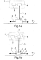
- FIG. 1a shows schematically a typical existing arrangement of a surface platform 1 with an AC electrical power source 2 (typically operating at 50 or 60 Hz) connecting to the power conductors within an umbilical 3 via an electrical power and control module (EPCM) 4.
- the seabed end of the umbilical 3 connects to a distribution assembly 5 on the seabed B, the assembly 5 feeding electrical power to a multiplicity of wells via power connections 6.
- FIG. 1b this shows schematically an arrangement operating according to an embodiment of the invention.
- items which correspond with those in Fig. 1a have the same reference numerals as Fig. 1a .
- the umbilical 3 has been compromised by the ingress of sea water, causing the capacitance between its power conductors and/or between its power conductors and earth to increase substantially with resultant increase of leakage currents and less power available to the well complex.
- An electronic converter 7 is installed in the EPCM 4 and receives AC electrical power from source 2 (typically at 50 or 60 Hz) and outputs electrical power at a lower frequency.
- source 2 typically at 50 or 60 Hz
- a frequency of 16 2/3 Hz is a favoured choice as communications on power (COP) electrical power control equipment operating at this frequency is readily available as a result of this frequency being a standard for the railway industry.
- the converter 7 to be one which simply rectifies the AC input power to produce DC electrical power and thus feed this DC electrical power down the umbilical 3 instead of AC electrical power. Both lower frequency AC and DC will substantially overcome the initial problem with the increased capacitance of the insulation of the compromised umbilical 3.
- a second electronic converter 8 is installed in the distribution assembly 5 or, as a possible alternative, is housed in a module on the seabed B and connected to the end of the umbilical 3 before it reaches the distribution assembly 5.
- the actual location of the subsea converter 8 will depend on the existing installation configuration.
- the converter 8 receives electrical power at the lower frequency, or DC, and outputs electrical power at the original power supply frequency for use by underwater equipment of the well complex via power connections 6.
- the converters 7 and 8 could be pre-installed at the surface location and subsea respectively, and switched into operation in the EPCM 4 and in the distribution assembly 5 or module if the monitoring equipment 9 indicates that the voltage of power from the power conductors in the umbilical 3 drops below a threshold.
- the present invention allows the problems of an umbilical which is failing due to water ingress to be substantially overcome, thus allowing a prolonged life for a well complex without having to replace the expensive umbilical.
Landscapes
- Engineering & Computer Science (AREA)
- Geology (AREA)
- Life Sciences & Earth Sciences (AREA)
- Mining & Mineral Resources (AREA)
- Physics & Mathematics (AREA)
- Power Engineering (AREA)
- General Life Sciences & Earth Sciences (AREA)
- Fluid Mechanics (AREA)
- Environmental & Geological Engineering (AREA)
- Geochemistry & Mineralogy (AREA)
- Mechanical Engineering (AREA)
- Geophysics (AREA)
- Laying Of Electric Cables Or Lines Outside (AREA)
- Investigating Or Analyzing Materials By The Use Of Electric Means (AREA)
- Prevention Of Electric Corrosion (AREA)
- Cable Transmission Systems, Equalization Of Radio And Reduction Of Echo (AREA)
- Other Liquid Machine Or Engine Such As Wave Power Use (AREA)
- Testing Relating To Insulation (AREA)
- Electric Cable Installation (AREA)
Abstract
Description
- The present invention relates to extending the life of a compromised umbilical.
- One of the most common problems with a subsea umbilical between a fluid extraction well surface platform and a well complex is degradation of the impedance of insulation between internal conductors of the umbilical and between the internal conductors and earth, i.e. the surrounding sea water. In practice, such an umbilical is compromised by the ingress of sea water, causing the capacitance between the conductors and/or between the conductors and earth to increase substantially, with resultant increase of leakage currents and less power available for the well complex. This invention enables a solution to this problem by saving the need to replace the umbilical.
- Various systems for providing electrical power to an underwater location are described in:
GB-A-2 332 220 GB-A-2 382 600 WO01/84689 WO02/37640 US-A-5 444 184 ;US-A-4 646,083 ;US-A-4 636 934 ;WO01/71158 US-A-4 080 025 ; andUS-A-6 045 333 . - According to the present invention from one aspect, there is provided a method of using an umbilical between a surface location and an underwater location of an underwater fluid extraction well system, the umbilical carrying an electrical power conductor for transmitting to the underwater location electrical power from a source at the surface location at a first frequency, for use by underwater equipment of the well system, the method comprising the steps of:
- detecting that the umbilical has been compromised by the ingress of water and, in response thereto:
- converting electrical power from the source to electrical power at a second frequency, lower than the first frequency, or to DC electrical power;
- transmitting said electrical power at the second frequency or said DC electrical power to the underwater location via the conductor; and
- at the underwater location, converting said electrical power at the second frequency or said DC electrical power to electrical power at a frequency used by the underwater equipment of the well system.
- Typically, the frequency of electrical power used by underwater equipment of the well system is the same as the first frequency.
- The umbilical could be, for example, connected to a distribution unit at the underwater location or a module at the underwater location before a distribution unit of the well system.
- Typically, the underwater location is on the bed of a body of water surrounding the umbilical.
- Said detecting step could include monitoring the voltage of electrical power from the umbilical for use in producing an indication that the umbilical has been compromised by the ingress of water if the voltage is less than a threshold.
- Typically, the method includes the steps of:
- if it is detected that the umbilical has been compromised by the ingress of water, providing means at the surface location for converting said electrical power from the source at the first frequency to said electrical power at the second frequency or to said DC electrical power; and
- providing at the underwater location means for converting the electrical power at the second frequency or said DC electrical power to electrical power at said frequency used by underwater equipment of the well system.
- Alternatively, the method could include the steps of:
- if it is detected that the umbilical has been compromised by the ingress of water, causing first converting means, at the surface location, to convert said electrical power from the source at the first frequency to said electrical power at the second frequency or to said DC electrical power; and
- causing second converting means, at the underwater location, to convert the electrical power at the second frequency or said DC electrical power to electrical power at said frequency used by underwater equipment of the well system.
- According to the present invention from another aspect, there is provided an underwater fluid extraction well system, comprising:
- a source of electrical power at a first frequency at a surface location;
- an umbilical for transmitting electrical power from the source via an electrical conductor of the umbilical to an underwater location for use by underwater equipment of the well system; and
- means for detecting that the umbilical has been compromised by the ingress of water, wherein the system further comprises:
- first converting means, for use at the surface location, for converting electrical power from the source to electrical power at a second frequency, lower than the first frequency, or to DC electrical power; and
- second converting means, for use at the underwater location, for converting such electrical power at the second frequency or said DC electrical power to electrical power at a frequency used by said underwater equipment of the well system, so that, if said detecting means indicates that the umbilical is compromised by the ingress of water, said first converting means can be used to convert electrical power from the source to said second frequency or to DC, for transmission via said conductor to the underwater location, and said second converting means can be used to convert the electrical power at the second frequency or the DC electrical power to electrical power at the frequency used by said underwater equipment of the system.
- Said detecting means could comprise means for monitoring the voltage of electrical power from the umbilical for use in producing an indication that the umbilical is compromised by the ingress of water if the voltage is less than a threshold.
-
-
Fig. 1a shows schematically a typical existing arrangement using an umbilical; and -
Fig. 1b shows schematically an arrangement using an embodiment of the invention. - Referring first to
Fig. 1a , this shows schematically a typical existing arrangement of asurface platform 1 with an AC electrical power source 2 (typically operating at 50 or 60 Hz) connecting to the power conductors within an umbilical 3 via an electrical power and control module (EPCM) 4. The seabed end of theumbilical 3 connects to adistribution assembly 5 on the seabed B, theassembly 5 feeding electrical power to a multiplicity of wells viapower connections 6. - Referring to
Fig. 1b , this shows schematically an arrangement operating according to an embodiment of the invention. InFig. 1b , items which correspond with those inFig. 1a have the same reference numerals asFig. 1a . The umbilical 3 has been compromised by the ingress of sea water, causing the capacitance between its power conductors and/or between its power conductors and earth to increase substantially with resultant increase of leakage currents and less power available to the well complex. - An
electronic converter 7 is installed in theEPCM 4 and receives AC electrical power from source 2 (typically at 50 or 60 Hz) and outputs electrical power at a lower frequency. A frequency of 16 2/3 Hz is a favoured choice as communications on power (COP) electrical power control equipment operating at this frequency is readily available as a result of this frequency being a standard for the railway industry. A possible alternative is for theconverter 7 to be one which simply rectifies the AC input power to produce DC electrical power and thus feed this DC electrical power down the umbilical 3 instead of AC electrical power. Both lower frequency AC and DC will substantially overcome the initial problem with the increased capacitance of the insulation of the compromised umbilical 3. - At the seabed end of the umbilical 3, a second electronic converter 8 is installed in the
distribution assembly 5 or, as a possible alternative, is housed in a module on the seabed B and connected to the end of theumbilical 3 before it reaches thedistribution assembly 5. The actual location of the subsea converter 8 will depend on the existing installation configuration. The converter 8 receives electrical power at the lower frequency, or DC, and outputs electrical power at the original power supply frequency for use by underwater equipment of the well complex viapower connections 6. - An example of how it had been determined that the umbilical 3 had become compromised by the ingress of sea water is as follows.
Conventional monitoring equipment 9 at the underwater location, for example at the distribution assembly 5 (as shown) or a module before it, detected that the voltage of power from the power conductors in theumbilical 3 had dropped below a threshold, an indication to that effect sent to theplatform 1 being an indication of sea water ingress. This is an indication, on the one hand, to installconverter 7 inEPCM 4 and, on the other hand, to install converter 8 subsea, typically using a remotely operated vehicle (ROV). - Alternatively, the
converters 7 and 8 could be pre-installed at the surface location and subsea respectively, and switched into operation in theEPCM 4 and in thedistribution assembly 5 or module if themonitoring equipment 9 indicates that the voltage of power from the power conductors in the umbilical 3 drops below a threshold. - The present invention allows the problems of an umbilical which is failing due to water ingress to be substantially overcome, thus allowing a prolonged life for a well complex without having to replace the expensive umbilical.
Claims (10)
- A method of using an umbilical between a surface location and an underwater location of an underwater fluid extraction well system, the umbilical carrying an electrical power conductor for transmitting to the underwater location electrical power from a source at the surface location at a first frequency, for use by underwater equipment of the well system, the method comprising the steps of:detecting that the umbilical has been compromised by the ingress of water and, in response thereto:converting electrical power from the source to electrical power at a second frequency, lower than the first frequency, or to DC electrical power;transmitting said electrical power at the second frequency or said DC electrical power to the underwater location via the conductor; andat the underwater location, converting said electrical power at the second frequency or said DC electrical power to electrical power at a frequency used by the underwater equipment of the well system.
- A method according to claim 1, wherein the frequency of electrical power used by underwater equipment of the well system is the same as the first frequency.
- A method according to claim 1 or 2, wherein the umbilical is connected to a distribution unit at the underwater location.
- A method according to claim 1 or 2, wherein the umbilical is connected to a module at the underwater location before a distribution unit of the well system.
- A method according to any preceding claim, wherein the underwater location is on the bed of a body of water surrounding the umbilical.
- A method according to any preceding claim, wherein said detecting step includes monitoring the voltage of electrical power from the umbilical for use in producing an indication that the umbilical has been compromised by the ingress of water if the voltage is less than a threshold.
- A method according to any preceding claim, which includes the steps of:if it is detected that the umbilical has been compromised by the ingress of water, providing means at the surface location for converting said electrical power from the source at the first frequency to said electrical power at the second frequency or to said DC electrical power; andproviding at the underwater location means for converting the electrical power at the second frequency or said DC electrical power to electrical power at said frequency used by underwater equipment of the well system.
- A method according to any of claims 1 to 6, which includes the steps of:if it is detected that the umbilical has been compromised by the ingress of water, causing first converting means, at the surface location, to convert said electrical power from the source at the first frequency to said electrical power at the second frequency or to said DC electrical power; andcausing second converting means, at the underwater location, to convert the electrical power at the second frequency or said DC electrical power to electrical power at said frequency used by underwater equipment of the well system.
- An underwater fluid extraction well system, comprising:a source of electrical power at a first frequency at a surface location;an umbilical for transmitting electrical power from the source via an electrical conductor of the umbilical to an underwater location for use by underwater equipment of the well system; andmeans for detecting that the umbilical has been compromised by the ingress of water, wherein the system further comprises:first converting means, for use at the surface location, for converting electrical power from the source to electrical power at a second frequency, lower than the first frequency, or to DC electrical power; andsecond converting means, for use at the underwater location, for converting such electrical power at the second frequency or said DC electrical power to electrical power at a frequency used by said underwater equipment of the well system, so that, if said detecting means indicates that the umbilical is compromised by the ingress of water, said first converting means can be used to convert electrical power from the source to said second frequency or to DC, for transmission via said conductor to the underwater location, and said second converting means can be used to convert the electrical power at the second frequency or the DC electrical power to electrical power at the frequency used by said underwater equipment of the system.
- A system according to claim 9, wherein said detecting means comprises means for monitoring the voltage of electrical power from the umbilical for use in producing an indication that the umbilical is compromised by the ingress of water if the voltage is less than a threshold.
Priority Applications (6)
| Application Number | Priority Date | Filing Date | Title |
|---|---|---|---|
| SG2011036431A SG176387A1 (en) | 2010-05-27 | 2011-05-20 | Extending the life of a compromised umbilical |
| MYPI2011002262A MY157207A (en) | 2010-05-27 | 2011-05-20 | Extending the life of a compromised umbilical |
| BRPI1102490-9A BRPI1102490B1 (en) | 2010-05-27 | 2011-05-23 | methods of using an umbilical cable and underwater fluid extraction well system |
| AU2011202452A AU2011202452B9 (en) | 2010-05-27 | 2011-05-25 | Extending the life of a compromised umbilical |
| US13/116,380 US9650886B2 (en) | 2010-05-27 | 2011-05-26 | Extending the life of a compromised umbilical |
| CN201110161357.4A CN102359356B (en) | 2010-05-27 | 2011-05-27 | Extend the life-span of impaired umbilical cables |
Applications Claiming Priority (1)
| Application Number | Priority Date | Filing Date | Title |
|---|---|---|---|
| GB1008816.9A GB2480652B (en) | 2010-05-27 | 2010-05-27 | Extending the life of a compromised umbilical |
Publications (3)
| Publication Number | Publication Date |
|---|---|
| EP2390460A2 true EP2390460A2 (en) | 2011-11-30 |
| EP2390460A3 EP2390460A3 (en) | 2015-11-04 |
| EP2390460B1 EP2390460B1 (en) | 2016-12-28 |
Family
ID=42371037
Family Applications (1)
| Application Number | Title | Priority Date | Filing Date |
|---|---|---|---|
| EP10166268.2A Not-in-force EP2390460B1 (en) | 2010-05-27 | 2010-06-17 | Extending the life of a compromised umbilical |
Country Status (8)
| Country | Link |
|---|---|
| US (1) | US9650886B2 (en) |
| EP (1) | EP2390460B1 (en) |
| CN (1) | CN102359356B (en) |
| AU (1) | AU2011202452B9 (en) |
| BR (1) | BRPI1102490B1 (en) |
| GB (1) | GB2480652B (en) |
| MY (1) | MY157207A (en) |
| SG (1) | SG176387A1 (en) |
Cited By (2)
| Publication number | Priority date | Publication date | Assignee | Title |
|---|---|---|---|---|
| EP2339359A3 (en) * | 2009-12-10 | 2013-01-02 | Viper Subsea Limited | Line monitoring device |
| EP2801695A1 (en) * | 2013-05-08 | 2014-11-12 | Siemens Aktiengesellschaft | Subsea electrical unit and system |
Citations (10)
| Publication number | Priority date | Publication date | Assignee | Title |
|---|---|---|---|---|
| US4080025A (en) | 1976-05-03 | 1978-03-21 | Matra | Automatic connector for underwater connection |
| US4636934A (en) | 1984-05-21 | 1987-01-13 | Otis Engineering Corporation | Well valve control system |
| US4646083A (en) | 1984-04-26 | 1987-02-24 | Hydril Company | Borehole measurement and telemetry system |
| US5444184A (en) | 1992-02-12 | 1995-08-22 | Alcatel Kabel Norge As | Method and cable for transmitting communication signals and electrical power between two spaced-apart locations |
| GB2332220A (en) | 1997-12-10 | 1999-06-16 | Abb Seatec Ltd | Underwater hydrocarbon production systems |
| US6045333A (en) | 1997-12-01 | 2000-04-04 | Camco International, Inc. | Method and apparatus for controlling a submergible pumping system |
| WO2001071158A1 (en) | 2000-03-20 | 2001-09-27 | Kværner Oilfield Products As | Subsea production system |
| WO2001084689A1 (en) | 2000-04-28 | 2001-11-08 | Aker Engineering As | Distribution system for electrical power |
| WO2002037640A1 (en) | 2000-10-30 | 2002-05-10 | Cooper Cameron Corporation | Control and supply system |
| GB2382600A (en) | 2001-12-03 | 2003-06-04 | Abb Offshore Systems Ltd | Transmitting power to underwater hydrocarbon production systems |
Family Cites Families (9)
| Publication number | Priority date | Publication date | Assignee | Title |
|---|---|---|---|---|
| US4309734A (en) * | 1979-11-05 | 1982-01-05 | Trw Inc. | Methods and apparatus for limiting electrical current to a subsea petroleum installation |
| US20040043501A1 (en) | 1997-05-02 | 2004-03-04 | Baker Hughes Incorporated | Monitoring of downhole parameters and chemical injection utilizing fiber optics |
| GB9913600D0 (en) | 1999-06-12 | 1999-08-11 | Sensor Highway Ltd | Opto-electrical actuation system and method |
| US7615893B2 (en) | 2000-05-11 | 2009-11-10 | Cameron International Corporation | Electric control and supply system |
| US7699102B2 (en) | 2004-12-03 | 2010-04-20 | Halliburton Energy Services, Inc. | Rechargeable energy storage device in a downhole operation |
| MY140418A (en) * | 2006-01-27 | 2009-12-31 | Alpha Perisai Sdn Bhd | Electrical power transmission system |
| EP1918508A1 (en) | 2006-10-31 | 2008-05-07 | Shell Internationale Researchmaatschappij B.V. | Method and system for providing electrical power to downhole well equipment |
| GB2443559B (en) * | 2006-11-06 | 2011-10-05 | Weatherford Lamb | Distributed temperature sensing in a remotely operated vehicle umbilical fiber optic cable |
| EP2071694B1 (en) * | 2007-12-11 | 2019-02-20 | General Electric Company | MVDC power transmission system for sub-sea loads |
-
2010
- 2010-05-27 GB GB1008816.9A patent/GB2480652B/en not_active Expired - Fee Related
- 2010-06-17 EP EP10166268.2A patent/EP2390460B1/en not_active Not-in-force
-
2011
- 2011-05-20 MY MYPI2011002262A patent/MY157207A/en unknown
- 2011-05-20 SG SG2011036431A patent/SG176387A1/en unknown
- 2011-05-23 BR BRPI1102490-9A patent/BRPI1102490B1/en not_active IP Right Cessation
- 2011-05-25 AU AU2011202452A patent/AU2011202452B9/en not_active Ceased
- 2011-05-26 US US13/116,380 patent/US9650886B2/en not_active Expired - Fee Related
- 2011-05-27 CN CN201110161357.4A patent/CN102359356B/en not_active Expired - Fee Related
Patent Citations (10)
| Publication number | Priority date | Publication date | Assignee | Title |
|---|---|---|---|---|
| US4080025A (en) | 1976-05-03 | 1978-03-21 | Matra | Automatic connector for underwater connection |
| US4646083A (en) | 1984-04-26 | 1987-02-24 | Hydril Company | Borehole measurement and telemetry system |
| US4636934A (en) | 1984-05-21 | 1987-01-13 | Otis Engineering Corporation | Well valve control system |
| US5444184A (en) | 1992-02-12 | 1995-08-22 | Alcatel Kabel Norge As | Method and cable for transmitting communication signals and electrical power between two spaced-apart locations |
| US6045333A (en) | 1997-12-01 | 2000-04-04 | Camco International, Inc. | Method and apparatus for controlling a submergible pumping system |
| GB2332220A (en) | 1997-12-10 | 1999-06-16 | Abb Seatec Ltd | Underwater hydrocarbon production systems |
| WO2001071158A1 (en) | 2000-03-20 | 2001-09-27 | Kværner Oilfield Products As | Subsea production system |
| WO2001084689A1 (en) | 2000-04-28 | 2001-11-08 | Aker Engineering As | Distribution system for electrical power |
| WO2002037640A1 (en) | 2000-10-30 | 2002-05-10 | Cooper Cameron Corporation | Control and supply system |
| GB2382600A (en) | 2001-12-03 | 2003-06-04 | Abb Offshore Systems Ltd | Transmitting power to underwater hydrocarbon production systems |
Cited By (4)
| Publication number | Priority date | Publication date | Assignee | Title |
|---|---|---|---|---|
| EP2339359A3 (en) * | 2009-12-10 | 2013-01-02 | Viper Subsea Limited | Line monitoring device |
| EP2801695A1 (en) * | 2013-05-08 | 2014-11-12 | Siemens Aktiengesellschaft | Subsea electrical unit and system |
| WO2014180615A3 (en) * | 2013-05-08 | 2015-07-16 | Siemens Aktiengesellschaft | Subsea electrical unit and system |
| US10138712B2 (en) | 2013-05-08 | 2018-11-27 | Siemens Aktiengesellschaft | Subsea electrical unit and system |
Also Published As
| Publication number | Publication date |
|---|---|
| US20160069176A1 (en) | 2016-03-10 |
| AU2011202452A1 (en) | 2011-12-15 |
| BRPI1102490A2 (en) | 2014-02-11 |
| SG176387A1 (en) | 2011-12-29 |
| CN102359356A (en) | 2012-02-22 |
| US9650886B2 (en) | 2017-05-16 |
| AU2011202452A8 (en) | 2016-09-22 |
| AU2011202452B8 (en) | 2016-09-22 |
| CN102359356B (en) | 2015-12-02 |
| AU2011202452B9 (en) | 2016-09-22 |
| MY157207A (en) | 2016-05-13 |
| BRPI1102490A8 (en) | 2016-04-05 |
| GB2480652B (en) | 2015-07-29 |
| BRPI1102490B1 (en) | 2020-01-28 |
| EP2390460B1 (en) | 2016-12-28 |
| GB201008816D0 (en) | 2010-07-14 |
| GB2480652A (en) | 2011-11-30 |
| AU2011202452B2 (en) | 2016-05-19 |
| EP2390460A3 (en) | 2015-11-04 |
Similar Documents
| Publication | Publication Date | Title |
|---|---|---|
| US8581741B2 (en) | Communication system for a hydrocarbon extraction plant | |
| US20110304289A1 (en) | Power Supply System and Method With Remote Variable Frequency Drive (VFD) | |
| EP1316672A1 (en) | Power supply means for underwater hydrocarbon production systems | |
| US9413564B2 (en) | Transmitting electrical power and communication signals | |
| CN102347644A (en) | Supplying power to underwater devices | |
| CN110753781A (en) | Underwater power and communication module | |
| EP2491660B1 (en) | System for communicating over a power cable | |
| EP2390460B1 (en) | Extending the life of a compromised umbilical | |
| WO2020242318A1 (en) | Subsea node for docking underwater intervention drones, method and system | |
| US10267841B2 (en) | Monitoring arrangement | |
| MY140418A (en) | Electrical power transmission system | |
| EP2833591A1 (en) | Subsea data communication interface unit | |
| EP2624469B1 (en) | Transmitting electrical power and data | |
| WO2017030701A1 (en) | Systems and methods for providing power and communications for downhole tools | |
| GB2463239A (en) | Subsea parking device |
Legal Events
| Date | Code | Title | Description |
|---|---|---|---|
| AK | Designated contracting states |
Kind code of ref document: A2 Designated state(s): AL AT BE BG CH CY CZ DE DK EE ES FI FR GB GR HR HU IE IS IT LI LT LU LV MC MK MT NL NO PL PT RO SE SI SK SM TR |
|
| AX | Request for extension of the european patent |
Extension state: BA ME RS |
|
| PUAI | Public reference made under article 153(3) epc to a published international application that has entered the european phase |
Free format text: ORIGINAL CODE: 0009012 |
|
| RAP1 | Party data changed (applicant data changed or rights of an application transferred) |
Owner name: GE OIL & GAS UK LIMITED |
|
| PUAL | Search report despatched |
Free format text: ORIGINAL CODE: 0009013 |
|
| AK | Designated contracting states |
Kind code of ref document: A3 Designated state(s): AL AT BE BG CH CY CZ DE DK EE ES FI FR GB GR HR HU IE IS IT LI LT LU LV MC MK MT NL NO PL PT RO SE SI SK SM TR |
|
| AX | Request for extension of the european patent |
Extension state: BA ME RS |
|
| RIC1 | Information provided on ipc code assigned before grant |
Ipc: E21B 33/035 20060101AFI20150929BHEP Ipc: H01R 13/707 20060101ALI20150929BHEP |
|
| 17P | Request for examination filed |
Effective date: 20160504 |
|
| RBV | Designated contracting states (corrected) |
Designated state(s): AL AT BE BG CH CY CZ DE DK EE ES FI FR GB GR HR HU IE IS IT LI LT LU LV MC MK MT NL NO PL PT RO SE SI SK SM TR |
|
| GRAJ | Information related to disapproval of communication of intention to grant by the applicant or resumption of examination proceedings by the epo deleted |
Free format text: ORIGINAL CODE: EPIDOSDIGR1 |
|
| GRAP | Despatch of communication of intention to grant a patent |
Free format text: ORIGINAL CODE: EPIDOSNIGR1 |
|
| INTG | Intention to grant announced |
Effective date: 20160831 |
|
| GRAS | Grant fee paid |
Free format text: ORIGINAL CODE: EPIDOSNIGR3 |
|
| GRAA | (expected) grant |
Free format text: ORIGINAL CODE: 0009210 |
|
| AK | Designated contracting states |
Kind code of ref document: B1 Designated state(s): AL AT BE BG CH CY CZ DE DK EE ES FI FR GB GR HR HU IE IS IT LI LT LU LV MC MK MT NL NO PL PT RO SE SI SK SM TR |
|
| REG | Reference to a national code |
Ref country code: GB Ref legal event code: FG4D |
|
| REG | Reference to a national code |
Ref country code: CH Ref legal event code: EP |
|
| REG | Reference to a national code |
Ref country code: AT Ref legal event code: REF Ref document number: 857473 Country of ref document: AT Kind code of ref document: T Effective date: 20170115 |
|
| REG | Reference to a national code |
Ref country code: IE Ref legal event code: FG4D |
|
| REG | Reference to a national code |
Ref country code: DE Ref legal event code: R096 Ref document number: 602010039099 Country of ref document: DE |
|
| PG25 | Lapsed in a contracting state [announced via postgrant information from national office to epo] |
Ref country code: LV Free format text: LAPSE BECAUSE OF FAILURE TO SUBMIT A TRANSLATION OF THE DESCRIPTION OR TO PAY THE FEE WITHIN THE PRESCRIBED TIME-LIMIT Effective date: 20161228 |
|
| REG | Reference to a national code |
Ref country code: NO Ref legal event code: T2 Effective date: 20161228 |
|
| REG | Reference to a national code |
Ref country code: LT Ref legal event code: MG4D |
|
| PG25 | Lapsed in a contracting state [announced via postgrant information from national office to epo] |
Ref country code: SE Free format text: LAPSE BECAUSE OF FAILURE TO SUBMIT A TRANSLATION OF THE DESCRIPTION OR TO PAY THE FEE WITHIN THE PRESCRIBED TIME-LIMIT Effective date: 20161228 Ref country code: LT Free format text: LAPSE BECAUSE OF FAILURE TO SUBMIT A TRANSLATION OF THE DESCRIPTION OR TO PAY THE FEE WITHIN THE PRESCRIBED TIME-LIMIT Effective date: 20161228 Ref country code: GR Free format text: LAPSE BECAUSE OF FAILURE TO SUBMIT A TRANSLATION OF THE DESCRIPTION OR TO PAY THE FEE WITHIN THE PRESCRIBED TIME-LIMIT Effective date: 20170329 |
|
| REG | Reference to a national code |
Ref country code: NL Ref legal event code: MP Effective date: 20161228 |
|
| REG | Reference to a national code |
Ref country code: AT Ref legal event code: MK05 Ref document number: 857473 Country of ref document: AT Kind code of ref document: T Effective date: 20161228 |
|
| PG25 | Lapsed in a contracting state [announced via postgrant information from national office to epo] |
Ref country code: HR Free format text: LAPSE BECAUSE OF FAILURE TO SUBMIT A TRANSLATION OF THE DESCRIPTION OR TO PAY THE FEE WITHIN THE PRESCRIBED TIME-LIMIT Effective date: 20161228 Ref country code: FI Free format text: LAPSE BECAUSE OF FAILURE TO SUBMIT A TRANSLATION OF THE DESCRIPTION OR TO PAY THE FEE WITHIN THE PRESCRIBED TIME-LIMIT Effective date: 20161228 |
|
| REG | Reference to a national code |
Ref country code: FR Ref legal event code: PLFP Year of fee payment: 8 |
|
| PG25 | Lapsed in a contracting state [announced via postgrant information from national office to epo] |
Ref country code: NL Free format text: LAPSE BECAUSE OF FAILURE TO SUBMIT A TRANSLATION OF THE DESCRIPTION OR TO PAY THE FEE WITHIN THE PRESCRIBED TIME-LIMIT Effective date: 20161228 |
|
| PG25 | Lapsed in a contracting state [announced via postgrant information from national office to epo] |
Ref country code: CZ Free format text: LAPSE BECAUSE OF FAILURE TO SUBMIT A TRANSLATION OF THE DESCRIPTION OR TO PAY THE FEE WITHIN THE PRESCRIBED TIME-LIMIT Effective date: 20161228 Ref country code: RO Free format text: LAPSE BECAUSE OF FAILURE TO SUBMIT A TRANSLATION OF THE DESCRIPTION OR TO PAY THE FEE WITHIN THE PRESCRIBED TIME-LIMIT Effective date: 20161228 Ref country code: SK Free format text: LAPSE BECAUSE OF FAILURE TO SUBMIT A TRANSLATION OF THE DESCRIPTION OR TO PAY THE FEE WITHIN THE PRESCRIBED TIME-LIMIT Effective date: 20161228 Ref country code: IS Free format text: LAPSE BECAUSE OF FAILURE TO SUBMIT A TRANSLATION OF THE DESCRIPTION OR TO PAY THE FEE WITHIN THE PRESCRIBED TIME-LIMIT Effective date: 20170428 Ref country code: EE Free format text: LAPSE BECAUSE OF FAILURE TO SUBMIT A TRANSLATION OF THE DESCRIPTION OR TO PAY THE FEE WITHIN THE PRESCRIBED TIME-LIMIT Effective date: 20161228 |
|
| PG25 | Lapsed in a contracting state [announced via postgrant information from national office to epo] |
Ref country code: PL Free format text: LAPSE BECAUSE OF FAILURE TO SUBMIT A TRANSLATION OF THE DESCRIPTION OR TO PAY THE FEE WITHIN THE PRESCRIBED TIME-LIMIT Effective date: 20161228 Ref country code: IT Free format text: LAPSE BECAUSE OF FAILURE TO SUBMIT A TRANSLATION OF THE DESCRIPTION OR TO PAY THE FEE WITHIN THE PRESCRIBED TIME-LIMIT Effective date: 20161228 Ref country code: BE Free format text: LAPSE BECAUSE OF FAILURE TO SUBMIT A TRANSLATION OF THE DESCRIPTION OR TO PAY THE FEE WITHIN THE PRESCRIBED TIME-LIMIT Effective date: 20161228 Ref country code: SM Free format text: LAPSE BECAUSE OF FAILURE TO SUBMIT A TRANSLATION OF THE DESCRIPTION OR TO PAY THE FEE WITHIN THE PRESCRIBED TIME-LIMIT Effective date: 20161228 Ref country code: BG Free format text: LAPSE BECAUSE OF FAILURE TO SUBMIT A TRANSLATION OF THE DESCRIPTION OR TO PAY THE FEE WITHIN THE PRESCRIBED TIME-LIMIT Effective date: 20170328 Ref country code: PT Free format text: LAPSE BECAUSE OF FAILURE TO SUBMIT A TRANSLATION OF THE DESCRIPTION OR TO PAY THE FEE WITHIN THE PRESCRIBED TIME-LIMIT Effective date: 20170428 Ref country code: AT Free format text: LAPSE BECAUSE OF FAILURE TO SUBMIT A TRANSLATION OF THE DESCRIPTION OR TO PAY THE FEE WITHIN THE PRESCRIBED TIME-LIMIT Effective date: 20161228 Ref country code: ES Free format text: LAPSE BECAUSE OF FAILURE TO SUBMIT A TRANSLATION OF THE DESCRIPTION OR TO PAY THE FEE WITHIN THE PRESCRIBED TIME-LIMIT Effective date: 20161228 |
|
| REG | Reference to a national code |
Ref country code: DE Ref legal event code: R097 Ref document number: 602010039099 Country of ref document: DE |
|
| PLBE | No opposition filed within time limit |
Free format text: ORIGINAL CODE: 0009261 |
|
| STAA | Information on the status of an ep patent application or granted ep patent |
Free format text: STATUS: NO OPPOSITION FILED WITHIN TIME LIMIT |
|
| PG25 | Lapsed in a contracting state [announced via postgrant information from national office to epo] |
Ref country code: DK Free format text: LAPSE BECAUSE OF FAILURE TO SUBMIT A TRANSLATION OF THE DESCRIPTION OR TO PAY THE FEE WITHIN THE PRESCRIBED TIME-LIMIT Effective date: 20161228 |
|
| 26N | No opposition filed |
Effective date: 20170929 |
|
| PG25 | Lapsed in a contracting state [announced via postgrant information from national office to epo] |
Ref country code: MC Free format text: LAPSE BECAUSE OF FAILURE TO SUBMIT A TRANSLATION OF THE DESCRIPTION OR TO PAY THE FEE WITHIN THE PRESCRIBED TIME-LIMIT Effective date: 20161228 |
|
| REG | Reference to a national code |
Ref country code: CH Ref legal event code: PL |
|
| GBPC | Gb: european patent ceased through non-payment of renewal fee |
Effective date: 20170617 |
|
| PG25 | Lapsed in a contracting state [announced via postgrant information from national office to epo] |
Ref country code: SI Free format text: LAPSE BECAUSE OF FAILURE TO SUBMIT A TRANSLATION OF THE DESCRIPTION OR TO PAY THE FEE WITHIN THE PRESCRIBED TIME-LIMIT Effective date: 20161228 |
|
| REG | Reference to a national code |
Ref country code: IE Ref legal event code: MM4A |
|
| PG25 | Lapsed in a contracting state [announced via postgrant information from national office to epo] |
Ref country code: GB Free format text: LAPSE BECAUSE OF NON-PAYMENT OF DUE FEES Effective date: 20170617 Ref country code: CH Free format text: LAPSE BECAUSE OF NON-PAYMENT OF DUE FEES Effective date: 20170630 Ref country code: LI Free format text: LAPSE BECAUSE OF NON-PAYMENT OF DUE FEES Effective date: 20170630 Ref country code: LU Free format text: LAPSE BECAUSE OF NON-PAYMENT OF DUE FEES Effective date: 20170617 Ref country code: IE Free format text: LAPSE BECAUSE OF NON-PAYMENT OF DUE FEES Effective date: 20170617 |
|
| REG | Reference to a national code |
Ref country code: FR Ref legal event code: PLFP Year of fee payment: 9 |
|
| PG25 | Lapsed in a contracting state [announced via postgrant information from national office to epo] |
Ref country code: MT Free format text: LAPSE BECAUSE OF NON-PAYMENT OF DUE FEES Effective date: 20170617 |
|
| PG25 | Lapsed in a contracting state [announced via postgrant information from national office to epo] |
Ref country code: HU Free format text: LAPSE BECAUSE OF FAILURE TO SUBMIT A TRANSLATION OF THE DESCRIPTION OR TO PAY THE FEE WITHIN THE PRESCRIBED TIME-LIMIT; INVALID AB INITIO Effective date: 20100617 |
|
| PG25 | Lapsed in a contracting state [announced via postgrant information from national office to epo] |
Ref country code: CY Free format text: LAPSE BECAUSE OF NON-PAYMENT OF DUE FEES Effective date: 20161228 |
|
| PG25 | Lapsed in a contracting state [announced via postgrant information from national office to epo] |
Ref country code: MK Free format text: LAPSE BECAUSE OF FAILURE TO SUBMIT A TRANSLATION OF THE DESCRIPTION OR TO PAY THE FEE WITHIN THE PRESCRIBED TIME-LIMIT Effective date: 20161228 |
|
| PG25 | Lapsed in a contracting state [announced via postgrant information from national office to epo] |
Ref country code: TR Free format text: LAPSE BECAUSE OF FAILURE TO SUBMIT A TRANSLATION OF THE DESCRIPTION OR TO PAY THE FEE WITHIN THE PRESCRIBED TIME-LIMIT Effective date: 20161228 |
|
| PG25 | Lapsed in a contracting state [announced via postgrant information from national office to epo] |
Ref country code: AL Free format text: LAPSE BECAUSE OF FAILURE TO SUBMIT A TRANSLATION OF THE DESCRIPTION OR TO PAY THE FEE WITHIN THE PRESCRIBED TIME-LIMIT Effective date: 20161228 |
|
| PGFP | Annual fee paid to national office [announced via postgrant information from national office to epo] |
Ref country code: DE Payment date: 20240521 Year of fee payment: 15 |
|
| PGFP | Annual fee paid to national office [announced via postgrant information from national office to epo] |
Ref country code: NO Payment date: 20240523 Year of fee payment: 15 Ref country code: FR Payment date: 20240522 Year of fee payment: 15 |
|
| REG | Reference to a national code |
Ref country code: DE Ref legal event code: R119 Ref document number: 602010039099 Country of ref document: DE |
|
| PG25 | Lapsed in a contracting state [announced via postgrant information from national office to epo] |
Ref country code: DE Free format text: LAPSE BECAUSE OF NON-PAYMENT OF DUE FEES Effective date: 20260101 Ref country code: NO Free format text: LAPSE BECAUSE OF NON-PAYMENT OF DUE FEES Effective date: 20250630 |
|
| PG25 | Lapsed in a contracting state [announced via postgrant information from national office to epo] |
Ref country code: FR Free format text: LAPSE BECAUSE OF NON-PAYMENT OF DUE FEES Effective date: 20250630 |