EP2390435B1 - A device for reducing movements of a roof underlay of a roof structure - Google Patents
A device for reducing movements of a roof underlay of a roof structure Download PDFInfo
- Publication number
- EP2390435B1 EP2390435B1 EP10163795A EP10163795A EP2390435B1 EP 2390435 B1 EP2390435 B1 EP 2390435B1 EP 10163795 A EP10163795 A EP 10163795A EP 10163795 A EP10163795 A EP 10163795A EP 2390435 B1 EP2390435 B1 EP 2390435B1
- Authority
- EP
- European Patent Office
- Prior art keywords
- batten
- roof
- underlay
- attachment means
- roof structure
- Prior art date
- Legal status (The legal status is an assumption and is not a legal conclusion. Google has not performed a legal analysis and makes no representation as to the accuracy of the status listed.)
- Active
Links
Images

Classifications
-
- E—FIXED CONSTRUCTIONS
- E04—BUILDING
- E04D—ROOF COVERINGS; SKY-LIGHTS; GUTTERS; ROOF-WORKING TOOLS
- E04D12/00—Non-structural supports for roofing materials, e.g. battens, boards
- E04D12/002—Sheets of flexible material, e.g. roofing tile underlay
-
- E—FIXED CONSTRUCTIONS
- E04—BUILDING
- E04D—ROOF COVERINGS; SKY-LIGHTS; GUTTERS; ROOF-WORKING TOOLS
- E04D12/00—Non-structural supports for roofing materials, e.g. battens, boards
- E04D12/004—Battens
Definitions
- the invention relates to elements for use in the building industry, particularly components used for reducing movements of a roof underlay in a roof structure.
- Roof structures often have structural elements such as rafters of wood as the carrying structural elements onto which battens are fixed that carry the outer roof.
- a roof underlay is often arranged between the rafters and the battens.
- the roof underlay serves as a vapour barrier and a wind stopper.
- wind may cause the roof underlay to move and flutter which may generate noise and eventually also wear or tear the roof underlay.
- motion damping devices are attached to battens or other structural elements of the roof structure and in contact with the roof underlay so as to reduce movements of the roof underlay.
- Such known devices are attached to a batten either using a nail or a piece of string or wire such as a metal wire. This is time consuming.
- WO 95/21974 discloses an example of such a vibration damper for a roof underlay that is attached by means of a nail.
- the invention provides a device for reducing movements of a roof underlay of a roof structure which device has attachment means for attaching the device to a batten of the roof structure, a contacting element for contacting the roof underlay, and an interconnecting element interconnecting the attachment means and the contacting element.
- the attachment means comprises resilient members dimensioned to span the batten, and snapping ridges on the resilient members for interacting with edges of the batten so as to allow the device to be attached to the batten by a snapping action of the resilient members and the snapping ridges. The user can simply snap the device onto the batten which will only take a few seconds and no tools are needed. If desirable the device may be removed or moved also without the use of tools.
- the interconnecting element is resilient whereby the device can adapt to the distance between the batten and the roof underlay and exert a mild force on the roof underlay.
- the length of the interconnecting element can be adjusted according to the distance between the batten and the roofing underlay, preferably by having one or more sections that can be broken off by the user to make is shorter.
- the surfaces of the attachment means facing the batten have protrusions for contacting the batten so as to provide a space between the attachment means and the batten.
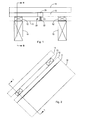
- FIG. 1 is shown an exemplary roof structure.
- Rafters 10 support the remaining roof structure including a roof underlay 11, counter battens or spacers 12, battens 13 and an outer roof 14 e.g. roof tiles.
- the elements of the roof structure are shown slightly exploded but will be fixed to each other to form a stable roof structure.
- EP 1209298 B1 discloses a laminate, especially for use as roof underlay.
- a device 20 of the invention is attached to the batten 13 by means of attachment means 21.
- a footplate 22 is in contact with the roof underlay 11 and a spring element 23 interconnects the attachment means 21 and the footplate 22 and the device will reduce movements of the roof underlay 11.
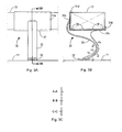
- FIGS 3A and 3B show a device 30 in an embodiment of the invention.
- the device 30 has attachment means 31a and 31b each having a protruding snapping ridge or hook 31a', 31b' at its end by means of which it is attached to a batten 13 of a roof structure e.g. the roof structure in figures 1 and 2 .
- a footplate 32 is in contact with a roof underlay 11, and an interconnecting element 33 interconnects the attachment means 31 and the footplate 32.
- the interconnecting element 33 is S-shaped and resilient.
- the entire device 30 is moulded in one piece of a mouldable material, preferably a durable and resilient thermoplastic material such as thermoplastic vulcanisates (TPV), propylene based elastomers and thermoplastic elastomers such as SEBS, and thermoplastic TPU.
- a durable and resilient thermoplastic material such as thermoplastic vulcanisates (TPV), propylene based elastomers and thermoplastic elastomers such as SEBS, and thermoplastic TPU.
- the material may also contain polypropylene.
- the user may first place one of the attachment means 31a or 31b with the corresponding protruding snapping ridge 31a' or 31b' on the batten 13 so that the snapping ridge grips over an edge of the batten. Then the user will flex the attachment means 31a, 31b apart so as to snap the other one of the protruding snapping ridge 31a' or 31b' grips over the diagonally opposite edge of the batten.
- the surfaces the attachment means 31a and 31b facing the batten 13 have protruding ribs or beads 34 that provide a space between the attachment means and the batten which ensures that air has access to the space to prevent accumulation of moisture between the attachment means and the batten.
- the footplate 22, 32 When attached to a batten as shown in figures 1 , 3A and 3B the footplate 22, 32 is preferably in contact with the roof underlay 11 which in itself reduces any transverse movements of the roof underlay, i.e. movements transverse to the plane of the roof underlay.
- the interconnecting element 23, 33 is preferably resilient whereby some movement of the roof underlay is possible and dynamic forces between the footplate and the roof underlay are reduced. This reduces the risk of tearing the roof underlay.
- FIG. 4 Alternative embodiments are shown in figures 4 to 7 when attached to a batten like in figure 3B .
- the attachment means for attaching the devices 40, 50, 60 and 70 to a batten 13 corresponds to what is described above in connection with figures 3A and 3B .
- the interconnecting element has different configurations that allow its properties to be varies and optimised for the purpose.
- the device can be manufactured with different length and dynamic properties such as resilience and stroke length.
- the interconnecting element has three footplates 42a-c, 52a-c, 62a-c and 72a-c, respectively at different distances from the batten.
- one or two of the lower footplates can be broken off.
Landscapes
- Engineering & Computer Science (AREA)
- Architecture (AREA)
- Civil Engineering (AREA)
- Structural Engineering (AREA)
- Roof Covering Using Slabs Or Stiff Sheets (AREA)
Description
- The invention relates to elements for use in the building industry, particularly components used for reducing movements of a roof underlay in a roof structure.
- Roof structures often have structural elements such as rafters of wood as the carrying structural elements onto which battens are fixed that carry the outer roof. A roof underlay is often arranged between the rafters and the battens. The roof underlay serves as a vapour barrier and a wind stopper. In case the roof underlay is a flexible sheet material wind may cause the roof underlay to move and flutter which may generate noise and eventually also wear or tear the roof underlay. For that purpose motion damping devices are attached to battens or other structural elements of the roof structure and in contact with the roof underlay so as to reduce movements of the roof underlay. Such known devices are attached to a batten either using a nail or a piece of string or wire such as a metal wire. This is time consuming.
WO 95/21974 - The invention provides a device for reducing movements of a roof underlay of a roof structure which device has attachment means for attaching the device to a batten of the roof structure, a contacting element for contacting the roof underlay, and an interconnecting element interconnecting the attachment means and the contacting element. According to the invention the attachment means comprises resilient members dimensioned to span the batten, and snapping ridges on the resilient members for interacting with edges of the batten so as to allow the device to be attached to the batten by a snapping action of the resilient members and the snapping ridges. The user can simply snap the device onto the batten which will only take a few seconds and no tools are needed. If desirable the device may be removed or moved also without the use of tools.
- Preferably, the interconnecting element is resilient whereby the device can adapt to the distance between the batten and the roof underlay and exert a mild force on the roof underlay. Advantageously the length of the interconnecting element can be adjusted according to the distance between the batten and the roofing underlay, preferably by having one or more sections that can be broken off by the user to make is shorter.
- In order to prevent water to accumulate between the attachment means and the batten, the surfaces of the attachment means facing the batten have protrusions for contacting the batten so as to provide a space between the attachment means and the batten.
-
-
Figure 1 is a schematical section through a roof structure seen in the direction of the arrows I-I infigure 2 ; -
Figure 2 is a schematical section through t roof structure infigure 1 seen in the direction of the arrows II-II infigure 1 ; -
Figure 3A shows a device according to the invention attached to a batten; -
Figure 3B shows a section through the device infigure 3A taken along theline 3B-3B infigure 3A ; -
Figure 3C shows three sections through the device infigures 3A and 3B taken along the lines A-A, B-B and C-C, respectively infigure 3B ; and -
Figures 4, 5, 6 and 7 show alternative embodiments of the device of the invention. - In
figures 1 and 2 is shown an exemplary roof structure.Rafters 10 support the remaining roof structure including aroof underlay 11, counter battens orspacers 12,battens 13 and anouter roof 14 e.g. roof tiles. The elements of the roof structure are shown slightly exploded but will be fixed to each other to form a stable roof structure.EP 1209298 B1 discloses a laminate, especially for use as roof underlay. Infigure 1 adevice 20 of the invention is attached to thebatten 13 by means of attachment means 21. Afootplate 22 is in contact with theroof underlay 11 and aspring element 23 interconnects the attachment means 21 and thefootplate 22 and the device will reduce movements of theroof underlay 11. -
Figures 3A and 3B show adevice 30 in an embodiment of the invention. Thedevice 30 has attachment means 31a and 31b each having a protruding snapping ridge orhook 31a', 31b' at its end by means of which it is attached to abatten 13 of a roof structure e.g. the roof structure infigures 1 and 2 . Afootplate 32 is in contact with aroof underlay 11, and an interconnectingelement 33 interconnects the attachment means 31 and thefootplate 32. The interconnectingelement 33 is S-shaped and resilient. Theentire device 30 is moulded in one piece of a mouldable material, preferably a durable and resilient thermoplastic material such as thermoplastic vulcanisates (TPV), propylene based elastomers and thermoplastic elastomers such as SEBS, and thermoplastic TPU. The material may also contain polypropylene. - When the
device 30 is to be attached to thebatten 13 the user may first place one of the attachment means 31a or 31b with the corresponding protrudingsnapping ridge 31a' or 31b' on thebatten 13 so that the snapping ridge grips over an edge of the batten. Then the user will flex the attachment means 31a, 31b apart so as to snap the other one of the protrudingsnapping ridge 31a' or 31b' grips over the diagonally opposite edge of the batten. The surfaces the attachment means 31a and 31b facing thebatten 13 have protruding ribs orbeads 34 that provide a space between the attachment means and the batten which ensures that air has access to the space to prevent accumulation of moisture between the attachment means and the batten. - When attached to a batten as shown in
figures 1 ,3A and 3B thefootplate roof underlay 11 which in itself reduces any transverse movements of the roof underlay, i.e. movements transverse to the plane of the roof underlay. The interconnectingelement - Alternative embodiments are shown in
figures 4 to 7 when attached to a batten like infigure 3B . The attachment means for attaching thedevices batten 13 corresponds to what is described above in connection withfigures 3A and 3B . Infigures 4 to 7 the interconnecting element has different configurations that allow its properties to be varies and optimised for the purpose. Thus e.g. the device can be manufactured with different length and dynamic properties such as resilience and stroke length. In each of the embodiments infigures 4 to 7 the interconnecting element has threefootplates 42a-c, 52a-c, 62a-c and 72a-c, respectively at different distances from the batten. If a shortening of the interconnecting element is desired due to the actual distance between the batten and the roof underlay, one or two of the lower footplates can be broken off. For this purpose there is a weakening of the material in the form of a notch or indentation that allows a footplate and its associated connector to be broken off leaving the remaining footplate without protruding edges that might otherwise damage the roof underlay.
Claims (6)
- A device (20, 30, 40, 50, 60, 70) for reducing movements of a roof underlay (11) of a roof structure, the device (20,30,40,50,60,70) comprising- attachment means (31) for attaching the device (20,30,40,50,60,70) to a batten (13) of the roof structure;- a contacting element (32) for contacting the roof underlay (11); and- an interconnecting element (33) interconnecting the attachment means (31) and the contacting element (32);characterized in that the attachment means (31) comprises resilient members (31a, 31b) dimensioned to span the batten (13), and snapping ridges (31a', 31b') on the resilient members (31a, 31b) for interacting with edges of the batten (13) so as to allow the device (20,30,40,50,60,70) to be attached to the batten (13) by a snapping action of the resilient members (31a, 31b) and the snapping ridges (31a', 31b').
- A device (20,30,40,50,60,70) according to claim 1 wherein the interconnecting element (33) is resilient.
- A device (20,30,40,50,60,70) according to any one of the preceding claims wherein the interconnecting element (33) has a length that can be adjusted according to the distance between the batten (13) and the roofing underlay (11).
- A device (20,30,40,50,60,70) according to claim 3 wherein the interconnecting element (33) has a weakening allowing a portion (42a, 42b, 52a, 52b, 62a, 62b, 72a, 72b) thereof to be broken off.
- A device (20,30,40,50,60,70) according to any one of the preceding claims wherein surfaces of the attachment means (31a, 31b) facing the batten (13) have protrusions (34) for contacting the batten (13) so as to provide a space between the attachment means (31a, 31b) and the batten (13).
- A device (20,30,40,50,60,70) according to any one of the preceding claims being of a mouldable material and moulded in one piece.
Priority Applications (4)
| Application Number | Priority Date | Filing Date | Title |
|---|---|---|---|
| PL10163795T PL2390435T3 (en) | 2010-05-25 | 2010-05-25 | A device for reducing movements of a roof underlay of a roof structure |
| DK10163795.7T DK2390435T3 (en) | 2010-05-25 | 2010-05-25 | Device for reducing movements of a roof structure's roof |
| EP10163795A EP2390435B1 (en) | 2010-05-25 | 2010-05-25 | A device for reducing movements of a roof underlay of a roof structure |
| PCT/DK2011/050172 WO2011147419A1 (en) | 2010-05-25 | 2011-05-25 | A device for reducing movements of a roof underlay of a roof structure |
Applications Claiming Priority (1)
| Application Number | Priority Date | Filing Date | Title |
|---|---|---|---|
| EP10163795A EP2390435B1 (en) | 2010-05-25 | 2010-05-25 | A device for reducing movements of a roof underlay of a roof structure |
Publications (2)
| Publication Number | Publication Date |
|---|---|
| EP2390435A1 EP2390435A1 (en) | 2011-11-30 |
| EP2390435B1 true EP2390435B1 (en) | 2012-12-19 |
Family
ID=42536371
Family Applications (1)
| Application Number | Title | Priority Date | Filing Date |
|---|---|---|---|
| EP10163795A Active EP2390435B1 (en) | 2010-05-25 | 2010-05-25 | A device for reducing movements of a roof underlay of a roof structure |
Country Status (4)
| Country | Link |
|---|---|
| EP (1) | EP2390435B1 (en) |
| DK (1) | DK2390435T3 (en) |
| PL (1) | PL2390435T3 (en) |
| WO (1) | WO2011147419A1 (en) |
Families Citing this family (3)
| Publication number | Priority date | Publication date | Assignee | Title |
|---|---|---|---|---|
| GB201618216D0 (en) * | 2016-10-27 | 2016-12-14 | Bowller Building Products Ltd | Roofing Installations |
| NO20200691A1 (en) * | 2020-06-14 | 2021-12-15 | Alexander Stene Utne | Low-profile fastening device for sound ceiling |
| PL132024U1 (en) * | 2024-03-15 | 2025-09-22 | Janiszyn Łukasz Pogotowie Dekarskie | Spacer shape for para-permeable membranes |
Family Cites Families (6)
| Publication number | Priority date | Publication date | Assignee | Title |
|---|---|---|---|---|
| DE3515419C1 (en) * | 1985-04-29 | 1986-08-14 | Walter Dipl.-Ing. 4630 Bochum Holzapfel | Spacers for spacing apart a roof substructure, provided beneath a roof covering, of the load-bearing roof structure |
| DE9309379U1 (en) * | 1993-06-24 | 1994-11-03 | Hebel Ag, 82275 Emmering | Support device for roof battens on a sloping solid roof |
| DK171083B1 (en) * | 1994-02-11 | 1996-05-28 | Polysheet As | Swivel damper for a roof |
| GB2318593A (en) * | 1996-10-24 | 1998-04-29 | David Frederick Martin | Roof batten spacer |
| ATE400711T1 (en) | 2000-11-22 | 2008-07-15 | Icopal As | MULTI-LAYER MATERIAL, ESPECIALLY FOR USE AS A SUB-ROOF |
| EP1316654A1 (en) * | 2001-11-29 | 2003-06-04 | Monarflex A/S | A distance element for use in a roof structure and a method of positioning and fixating a plurality of lathes in a roof structure |
-
2010
- 2010-05-25 EP EP10163795A patent/EP2390435B1/en active Active
- 2010-05-25 DK DK10163795.7T patent/DK2390435T3/en active
- 2010-05-25 PL PL10163795T patent/PL2390435T3/en unknown
-
2011
- 2011-05-25 WO PCT/DK2011/050172 patent/WO2011147419A1/en not_active Ceased
Also Published As
| Publication number | Publication date |
|---|---|
| WO2011147419A1 (en) | 2011-12-01 |
| DK2390435T3 (en) | 2013-03-25 |
| PL2390435T3 (en) | 2013-09-30 |
| EP2390435A1 (en) | 2011-11-30 |
Similar Documents
| Publication | Publication Date | Title |
|---|---|---|
| EP4134599B1 (en) | Device and method for fixing a support structure for a solar panel to a corrugated roof | |
| US20240068239A1 (en) | Corrugated Mesh Gutter Leaf Preclusion System | |
| EP2195496B1 (en) | Wedge set, especially for use in fastening floor joists | |
| US6164024A (en) | Architectural glazing panel system and retaining clip therefor | |
| EP2315884B1 (en) | A mounting bracket for a roof penetrating structure | |
| USD581511S1 (en) | Baffle vent with transverse ribs for use in roof ventilation | |
| WO2006117605A3 (en) | Roofing assembly having high resistance for use with roofs of residential and industrial buildings | |
| JP2013513040A (en) | Mounting system for solar panels, mounting rails and fastening devices | |
| US20130031846A1 (en) | Shielding device and associated methods | |
| EP2390435A1 (en) | A device for reducing movements of a roof underlay of a roof structure | |
| JP2019094772A (en) | Shearing tie system for ventilation type roof ridge | |
| US20080216442A1 (en) | Roofing system | |
| US9670672B2 (en) | Roof panel system | |
| AU2016259292B2 (en) | A clip | |
| US20110252732A1 (en) | Contraction and expansion management (CEM) joint | |
| EP2614197A1 (en) | Snow stopper for roof | |
| EP3002381A1 (en) | Roofing system | |
| AU2010100770B4 (en) | A clip | |
| JP4145900B2 (en) | Roofing structure of roofing material | |
| AU2018358053A1 (en) | Brick tie gap connector | |
| WO1995021974A1 (en) | A vibration damper for an underroof | |
| AU2010100788A4 (en) | A structure for accommodating wind loads | |
| EP2037075A2 (en) | Improved panel curtain system with co-acting profiles | |
| EP2058449A3 (en) | Mounting assembly for roof covering | |
| EP3656940B1 (en) | Sill-pad |
Legal Events
| Date | Code | Title | Description |
|---|---|---|---|
| AK | Designated contracting states |
Kind code of ref document: A1 Designated state(s): AL AT BE BG CH CY CZ DE DK EE ES FI FR GB GR HR HU IE IS IT LI LT LU LV MC MK MT NL NO PL PT RO SE SI SK SM TR |
|
| AX | Request for extension of the european patent |
Extension state: BA ME RS |
|
| PUAI | Public reference made under article 153(3) epc to a published international application that has entered the european phase |
Free format text: ORIGINAL CODE: 0009012 |
|
| 17P | Request for examination filed |
Effective date: 20120510 |
|
| GRAP | Despatch of communication of intention to grant a patent |
Free format text: ORIGINAL CODE: EPIDOSNIGR1 |
|
| GRAS | Grant fee paid |
Free format text: ORIGINAL CODE: EPIDOSNIGR3 |
|
| GRAA | (expected) grant |
Free format text: ORIGINAL CODE: 0009210 |
|
| AK | Designated contracting states |
Kind code of ref document: B1 Designated state(s): AL AT BE BG CH CY CZ DE DK EE ES FI FR GB GR HR HU IE IS IT LI LT LU LV MC MK MT NL NO PL PT RO SE SI SK SM TR |
|
| REG | Reference to a national code |
Ref country code: GB Ref legal event code: FG4D |
|
| REG | Reference to a national code |
Ref country code: CH Ref legal event code: EP |
|
| REG | Reference to a national code |
Ref country code: AT Ref legal event code: REF Ref document number: 589516 Country of ref document: AT Kind code of ref document: T Effective date: 20130115 |
|
| REG | Reference to a national code |
Ref country code: DE Ref legal event code: R096 Ref document number: 602010004152 Country of ref document: DE Effective date: 20130207 |
|
| REG | Reference to a national code |
Ref country code: DK Ref legal event code: T3 |
|
| REG | Reference to a national code |
Ref country code: SE Ref legal event code: TRGR |
|
| PG25 | Lapsed in a contracting state [announced via postgrant information from national office to epo] |
Ref country code: ES Free format text: LAPSE BECAUSE OF FAILURE TO SUBMIT A TRANSLATION OF THE DESCRIPTION OR TO PAY THE FEE WITHIN THE PRESCRIBED TIME-LIMIT Effective date: 20130330 |
|
| REG | Reference to a national code |
Ref country code: NL Ref legal event code: T3 |
|
| REG | Reference to a national code |
Ref country code: NO Ref legal event code: T2 Effective date: 20121219 |
|
| PG25 | Lapsed in a contracting state [announced via postgrant information from national office to epo] |
Ref country code: SI Free format text: LAPSE BECAUSE OF FAILURE TO SUBMIT A TRANSLATION OF THE DESCRIPTION OR TO PAY THE FEE WITHIN THE PRESCRIBED TIME-LIMIT Effective date: 20121219 Ref country code: GR Free format text: LAPSE BECAUSE OF FAILURE TO SUBMIT A TRANSLATION OF THE DESCRIPTION OR TO PAY THE FEE WITHIN THE PRESCRIBED TIME-LIMIT Effective date: 20130320 |
|
| PG25 | Lapsed in a contracting state [announced via postgrant information from national office to epo] |
Ref country code: SK Free format text: LAPSE BECAUSE OF FAILURE TO SUBMIT A TRANSLATION OF THE DESCRIPTION OR TO PAY THE FEE WITHIN THE PRESCRIBED TIME-LIMIT Effective date: 20121219 Ref country code: BG Free format text: LAPSE BECAUSE OF FAILURE TO SUBMIT A TRANSLATION OF THE DESCRIPTION OR TO PAY THE FEE WITHIN THE PRESCRIBED TIME-LIMIT Effective date: 20130319 Ref country code: IS Free format text: LAPSE BECAUSE OF FAILURE TO SUBMIT A TRANSLATION OF THE DESCRIPTION OR TO PAY THE FEE WITHIN THE PRESCRIBED TIME-LIMIT Effective date: 20130419 |
|
| PGFP | Annual fee paid to national office [announced via postgrant information from national office to epo] |
Ref country code: EE Payment date: 20130513 Year of fee payment: 4 Ref country code: LT Payment date: 20130423 Year of fee payment: 4 Ref country code: CZ Payment date: 20130517 Year of fee payment: 4 |
|
| REG | Reference to a national code |
Ref country code: EE Ref legal event code: FG4A Ref document number: E008092 Country of ref document: EE Effective date: 20130319 |
|
| PG25 | Lapsed in a contracting state [announced via postgrant information from national office to epo] |
Ref country code: RO Free format text: LAPSE BECAUSE OF FAILURE TO SUBMIT A TRANSLATION OF THE DESCRIPTION OR TO PAY THE FEE WITHIN THE PRESCRIBED TIME-LIMIT Effective date: 20121219 Ref country code: PT Free format text: LAPSE BECAUSE OF FAILURE TO SUBMIT A TRANSLATION OF THE DESCRIPTION OR TO PAY THE FEE WITHIN THE PRESCRIBED TIME-LIMIT Effective date: 20130419 |
|
| PGFP | Annual fee paid to national office [announced via postgrant information from national office to epo] |
Ref country code: LV Payment date: 20130513 Year of fee payment: 4 |
|
| REG | Reference to a national code |
Ref country code: PL Ref legal event code: T3 |
|
| PLBE | No opposition filed within time limit |
Free format text: ORIGINAL CODE: 0009261 |
|
| STAA | Information on the status of an ep patent application or granted ep patent |
Free format text: STATUS: NO OPPOSITION FILED WITHIN TIME LIMIT |
|
| 26N | No opposition filed |
Effective date: 20130920 |
|
| PG25 | Lapsed in a contracting state [announced via postgrant information from national office to epo] |
Ref country code: CY Free format text: LAPSE BECAUSE OF FAILURE TO SUBMIT A TRANSLATION OF THE DESCRIPTION OR TO PAY THE FEE WITHIN THE PRESCRIBED TIME-LIMIT Effective date: 20121219 Ref country code: HR Free format text: LAPSE BECAUSE OF FAILURE TO SUBMIT A TRANSLATION OF THE DESCRIPTION OR TO PAY THE FEE WITHIN THE PRESCRIBED TIME-LIMIT Effective date: 20121219 |
|
| PG25 | Lapsed in a contracting state [announced via postgrant information from national office to epo] |
Ref country code: MC Free format text: LAPSE BECAUSE OF FAILURE TO SUBMIT A TRANSLATION OF THE DESCRIPTION OR TO PAY THE FEE WITHIN THE PRESCRIBED TIME-LIMIT Effective date: 20121219 |
|
| REG | Reference to a national code |
Ref country code: DE Ref legal event code: R097 Ref document number: 602010004152 Country of ref document: DE Effective date: 20130920 |
|
| REG | Reference to a national code |
Ref country code: IE Ref legal event code: MM4A |
|
| PG25 | Lapsed in a contracting state [announced via postgrant information from national office to epo] |
Ref country code: IE Free format text: LAPSE BECAUSE OF NON-PAYMENT OF DUE FEES Effective date: 20130525 |
|
| PGFP | Annual fee paid to national office [announced via postgrant information from national office to epo] |
Ref country code: LU Payment date: 20140527 Year of fee payment: 5 |
|
| PGFP | Annual fee paid to national office [announced via postgrant information from national office to epo] |
Ref country code: FI Payment date: 20140513 Year of fee payment: 5 Ref country code: IT Payment date: 20140522 Year of fee payment: 5 Ref country code: SE Payment date: 20140520 Year of fee payment: 5 |
|
| PGFP | Annual fee paid to national office [announced via postgrant information from national office to epo] |
Ref country code: BE Payment date: 20140523 Year of fee payment: 5 Ref country code: PL Payment date: 20140424 Year of fee payment: 5 |
|
| REG | Reference to a national code |
Ref country code: LT Ref legal event code: MM4D Effective date: 20140525 |
|
| REG | Reference to a national code |
Ref country code: CH Ref legal event code: PL |
|
| REG | Reference to a national code |
Ref country code: EE Ref legal event code: MM4A Ref document number: E008092 Country of ref document: EE Effective date: 20140531 |
|
| GBPC | Gb: european patent ceased through non-payment of renewal fee |
Effective date: 20140525 |
|
| PG25 | Lapsed in a contracting state [announced via postgrant information from national office to epo] |
Ref country code: CH Free format text: LAPSE BECAUSE OF NON-PAYMENT OF DUE FEES Effective date: 20140531 Ref country code: LT Free format text: LAPSE BECAUSE OF NON-PAYMENT OF DUE FEES Effective date: 20140525 Ref country code: LI Free format text: LAPSE BECAUSE OF NON-PAYMENT OF DUE FEES Effective date: 20140531 Ref country code: EE Free format text: LAPSE BECAUSE OF NON-PAYMENT OF DUE FEES Effective date: 20140531 Ref country code: CZ Free format text: LAPSE BECAUSE OF NON-PAYMENT OF DUE FEES Effective date: 20140525 |
|
| PG25 | Lapsed in a contracting state [announced via postgrant information from national office to epo] |
Ref country code: LV Free format text: LAPSE BECAUSE OF NON-PAYMENT OF DUE FEES Effective date: 20140525 Ref country code: MT Free format text: LAPSE BECAUSE OF FAILURE TO SUBMIT A TRANSLATION OF THE DESCRIPTION OR TO PAY THE FEE WITHIN THE PRESCRIBED TIME-LIMIT Effective date: 20121219 |
|
| REG | Reference to a national code |
Ref country code: FR Ref legal event code: PLFP Year of fee payment: 6 |
|
| PG25 | Lapsed in a contracting state [announced via postgrant information from national office to epo] |
Ref country code: GB Free format text: LAPSE BECAUSE OF NON-PAYMENT OF DUE FEES Effective date: 20140525 Ref country code: SM Free format text: LAPSE BECAUSE OF FAILURE TO SUBMIT A TRANSLATION OF THE DESCRIPTION OR TO PAY THE FEE WITHIN THE PRESCRIBED TIME-LIMIT Effective date: 20121219 |
|
| PG25 | Lapsed in a contracting state [announced via postgrant information from national office to epo] |
Ref country code: TR Free format text: LAPSE BECAUSE OF FAILURE TO SUBMIT A TRANSLATION OF THE DESCRIPTION OR TO PAY THE FEE WITHIN THE PRESCRIBED TIME-LIMIT Effective date: 20121219 |
|
| PG25 | Lapsed in a contracting state [announced via postgrant information from national office to epo] |
Ref country code: HU Free format text: LAPSE BECAUSE OF FAILURE TO SUBMIT A TRANSLATION OF THE DESCRIPTION OR TO PAY THE FEE WITHIN THE PRESCRIBED TIME-LIMIT; INVALID AB INITIO Effective date: 20100525 Ref country code: MK Free format text: LAPSE BECAUSE OF FAILURE TO SUBMIT A TRANSLATION OF THE DESCRIPTION OR TO PAY THE FEE WITHIN THE PRESCRIBED TIME-LIMIT Effective date: 20121219 |
|
| PG25 | Lapsed in a contracting state [announced via postgrant information from national office to epo] |
Ref country code: IT Free format text: LAPSE BECAUSE OF NON-PAYMENT OF DUE FEES Effective date: 20150525 Ref country code: LU Free format text: LAPSE BECAUSE OF NON-PAYMENT OF DUE FEES Effective date: 20150525 Ref country code: FI Free format text: LAPSE BECAUSE OF NON-PAYMENT OF DUE FEES Effective date: 20150525 |
|
| PG25 | Lapsed in a contracting state [announced via postgrant information from national office to epo] |
Ref country code: SE Free format text: LAPSE BECAUSE OF NON-PAYMENT OF DUE FEES Effective date: 20150526 |
|
| REG | Reference to a national code |
Ref country code: FR Ref legal event code: PLFP Year of fee payment: 7 |
|
| REG | Reference to a national code |
Ref country code: AT Ref legal event code: MM01 Ref document number: 589516 Country of ref document: AT Kind code of ref document: T Effective date: 20150525 |
|
| PG25 | Lapsed in a contracting state [announced via postgrant information from national office to epo] |
Ref country code: PL Free format text: LAPSE BECAUSE OF NON-PAYMENT OF DUE FEES Effective date: 20150525 Ref country code: AT Free format text: LAPSE BECAUSE OF NON-PAYMENT OF DUE FEES Effective date: 20150525 |
|
| REG | Reference to a national code |
Ref country code: FR Ref legal event code: PLFP Year of fee payment: 8 |
|
| PG25 | Lapsed in a contracting state [announced via postgrant information from national office to epo] |
Ref country code: BE Free format text: LAPSE BECAUSE OF NON-PAYMENT OF DUE FEES Effective date: 20150531 |
|
| REG | Reference to a national code |
Ref country code: FR Ref legal event code: PLFP Year of fee payment: 9 |
|
| PG25 | Lapsed in a contracting state [announced via postgrant information from national office to epo] |
Ref country code: AL Free format text: LAPSE BECAUSE OF FAILURE TO SUBMIT A TRANSLATION OF THE DESCRIPTION OR TO PAY THE FEE WITHIN THE PRESCRIBED TIME-LIMIT Effective date: 20121219 |
|
| PGFP | Annual fee paid to national office [announced via postgrant information from national office to epo] |
Ref country code: NL Payment date: 20250522 Year of fee payment: 16 |
|
| PGFP | Annual fee paid to national office [announced via postgrant information from national office to epo] |
Ref country code: DE Payment date: 20250519 Year of fee payment: 16 |
|
| PGFP | Annual fee paid to national office [announced via postgrant information from national office to epo] |
Ref country code: DK Payment date: 20250521 Year of fee payment: 16 |
|
| PGFP | Annual fee paid to national office [announced via postgrant information from national office to epo] |
Ref country code: NO Payment date: 20250520 Year of fee payment: 16 |
|
| PGFP | Annual fee paid to national office [announced via postgrant information from national office to epo] |
Ref country code: FR Payment date: 20250523 Year of fee payment: 16 |