EP2390111A1 - Bicycle wheel spoke assembly - Google Patents
Bicycle wheel spoke assembly Download PDFInfo
- Publication number
- EP2390111A1 EP2390111A1 EP11165035A EP11165035A EP2390111A1 EP 2390111 A1 EP2390111 A1 EP 2390111A1 EP 11165035 A EP11165035 A EP 11165035A EP 11165035 A EP11165035 A EP 11165035A EP 2390111 A1 EP2390111 A1 EP 2390111A1
- Authority
- EP
- European Patent Office
- Prior art keywords
- spoke
- nut
- bicycle wheel
- main body
- spoke nut
- Prior art date
- Legal status (The legal status is an assumption and is not a legal conclusion. Google has not performed a legal analysis and makes no representation as to the accuracy of the status listed.)
- Granted
Links
Images






Classifications
-
- B—PERFORMING OPERATIONS; TRANSPORTING
- B60—VEHICLES IN GENERAL
- B60B—VEHICLE WHEELS; CASTORS; AXLES FOR WHEELS OR CASTORS; INCREASING WHEEL ADHESION
- B60B1/00—Spoked wheels; Spokes thereof
- B60B1/003—Spoked wheels; Spokes thereof specially adapted for bicycles
-
- B—PERFORMING OPERATIONS; TRANSPORTING
- B60—VEHICLES IN GENERAL
- B60B—VEHICLE WHEELS; CASTORS; AXLES FOR WHEELS OR CASTORS; INCREASING WHEEL ADHESION
- B60B1/00—Spoked wheels; Spokes thereof
- B60B1/02—Wheels with wire or other tension spokes
- B60B1/04—Attaching spokes to rim or hub
- B60B1/041—Attaching spokes to rim or hub of bicycle wheels
-
- B—PERFORMING OPERATIONS; TRANSPORTING
- B60—VEHICLES IN GENERAL
- B60B—VEHICLE WHEELS; CASTORS; AXLES FOR WHEELS OR CASTORS; INCREASING WHEEL ADHESION
- B60B21/00—Rims
- B60B21/06—Rims characterised by means for attaching spokes, i.e. spoke seats
- B60B21/062—Rims characterised by means for attaching spokes, i.e. spoke seats for bicycles
Definitions
- This invention generally relates to a bicycle wheel spoke assembly. More specifically, the present invention relates to bicycle wheel spoke assembly with a spoke nut configured to non-rotatably engage a wheel hub.
- Bicycling is becoming an increasingly more popular form of recreation as well as a means of transportation. Moreover, bicycling has become a very popular competitive sport for both amateurs and professionals. Whether the bicycle is used for recreation, transportation or competition, the bicycle industry is constantly improving the various components of the bicycle.
- One aspect is to provide a spoke assembly having a spoke that includes a flattened profile with a hub attachment configuration that prevents rotation of the spoke relative to the hub.
- a bicycle wheel spoke assembly a spoke and a spoke nut.
- the spoke has a rim attachment end and a hub attachment end.
- the spoke nut has a main body with a cylindrical shaped outer surface and a bore extending at least partially through the main body.
- the outer surface has at least one axially extending rib configured for engagement with a spoke aperture of a bicycle wheel hub.
- the bore of the main body of the spoke nut includes threads with the hub attachment end of the spoke being threadedly secured within the bore.
- Figure 1 is a side elevational view of a bicycle wheel that includes a plurality of spoke assemblies that extend between a hub and a rim of the bicycle wheel in accordance with a first embodiment
- Figure 2 is a side elevational view of the hub showing a portion of each of the plurality of spoke assemblies in accordance with the first embodiment
- Figure 3 is an exploded view of one of the spoke assemblies of the plurality of spoke assemblies shown removed from the bicycle wheel, showing spoke, a spoke nipple and a spoke nut in accordance with the first embodiment;
- Figure 4 is a side elevational view of the spoke assembly depicted in Figure 3 , shown with the spoke nipple and the spoke nut installed on the spoke in accordance with the first embodiment;
- Figure 5 is a cross-sectional view of the spoke taken along the line 5-5 in Figure 3 in accordance with the first embodiment
- Figure 6 is a cross-sectional view of the spoke taken along the line 6-6 in Figure 3 in accordance with the first embodiment
- Figure 7 is a side elevational view of the spoke nut shown removed from the spoke having three axially extending ribs on an outer surface of the spoke nut in accordance with the first embodiment;
- Figure 8 is an end view of the spoke nut shown removed from the spoke further showing the three axially extending ribs on the outer surface of the spoke nut in accordance with the first embodiment
- Figure 9 is a perspective view of the spoke nut showing internal threads that extend the length of a central aperture of the spoke nut in accordance with the first embodiment
- Figure 10 is a side elevational view of the hub showing one of the spokes being installed to the hub in accordance with the first embodiment
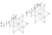
- Figure 11 is another side elevational view of the hub similar to Figure 10 showing the spoke nut being installed to the spoke in accordance with the first embodiment;
- Figure 12 is another side elevational view of the hub similar to Figures 10 and 11 showing the spoke nut being installed to the hub in accordance with the first embodiment;
- Figure 13 is a side elevational view of the bicycle wheel showing the spoke and the spoke nipple just prior to installation of the spoke nipple the rim in accordance with the first embodiment;
- Figure 14 is another side elevational view of the bicycle wheel similar to Figure 13 showing the spoke and the spoke nipple being installed to the rim in accordance with the first embodiment;
- Figure 15 is a perspective view of a portion of the hub showing a projection with a spoke receiving opening in accordance with the first embodiment
- Figure 16 is an exploded cross-sectional view of the portion of the hub showing the spoke receiving opening of the projection and the spoke nut, with the spoke nut ready for installation into the spoke receiving opening in accordance with the first embodiment;
- Figure 17 is another cross-sectional view of the portion of the hub showing the spoke nut installed within the spoke receiving opening of the projection in accordance with the first embodiment
- Figure 18 is a perspective view of a portion of a hub showing a projection with a spoke receiving opening that includes a plurality of recesses in accordance with a second embodiment
- Figure 19 is an exploded cross-sectional view of the portion of the hub showing the spoke receiving opening of the projection with the spoke nut ready for installation into the spoke receiving opening in accordance with the second embodiment;
- Figure 20 is another cross-sectional view of the portion of the hub similar to Figure 19 showing the spoke nut installed in the spoke receiving opening in accordance with the second embodiment;
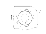
- Figure 21 is an end view of the portion of the hub showing ribs of the spoke nut installed in several of the recesses of the spoke receiving opening in accordance with the second embodiment.
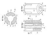
- Figure 22 is a perspective view of an alternative spoke nut, as used in a third embodiment.
- Figure 23 is a lengthwise sectional view of the spoke nut as shown in Figure 22 .
- Figure 24 is a cross-sectional view of the spoke nut as illustrated in Figures 22 and 23 according to a sectional level as indicated in Figure 23 .
- Figure 25 is a cross-sectional view of a portion of a hub according to the third embodiment showing the spoke nut ready for installation into the spoke receiving opening.
- Figure 26 is another cross-sectional view similar to Figure 25 , however after having inserted the spoke nut into the spoke receiving opening.
- Figure 27 is an end view of the portion of the hub showing the spoke nut installed in accordance with the third embodiment.
- Figure 28 is a detailed view of a spoke with the spoke nut attached thereto and both inserted into a spoke and spoke nut receiving hole still according to the third embodiment.
- a bicycle wheel 10 is illustrated with plurality of spoke assemblies 12 in accordance with a first embodiment.
- the bicycle wheel 10 includes a rim 14, a hub 16 and the plurality of spoke assemblies 12.
- the rim 14 is an annular member that includes a conventional tire receiving recess 18 (see Figures 13 and 14 ) and a radially extending inner surface 20.
- a tire 22 is mounted to the rim 14 in a conventional manner.
- the inner surface 20 includes a plurality of threaded apertures 24 whose purpose is described in greater detail below along with a description of the plurality of spoke assemblies 12.
- the hub 16 includes a main body 30, a central opening 32, and a plurality of projections 34.
- the main body 30 can be made of any of a variety of materials, such as steel, aluminum, or other light weight metals or metal alloys.
- the central opening 32 is dimensioned to receive an axle assembly 36 that includes a conventional axle 38 and bearings (not shown) that allow the bicycle wheel 10 to freely rotate about the axle 38 in a conventional manner.
- Each of the projections 34 of the hub 16 includes a pair of spoke receiving apertures 40.
- the spoke receiving apertures 40 in each projection are the same, but extend in opposing directions. Since they are the same, a description of only one of the spoke receiving apertures 40 is provided for the sake of brevity, but applies to both spoke receiving apertures 40.
- each of the spoke receiving apertures 40 includes a first section 42 and a second section 44.
- the first section 42 has first diameter D 1 and the second section 44 has a second diameter D 2 that is larger than the first diameter D 1 . Consequently, the second section 44 is wider than the first section 42.
- the first section 42 of the spoke receiving aperture is a spoke receiving section such that a portion of the spoke assembly 12 extends therethrough.
- the second section 44 of the spoke receiving aperture is a spoke nut receiving section such that a spoke nut 54 (described below) of the spoke assembly 12 is installable therein.
- the second section 44 (and optionally the first section 42) of the spoke receiving apertures 40 has a smooth cylindrically shaped surface.
- the spoke assembly 12 includes a spoke 50, a spoke nipple 52 and the spoke nut 54.
- the spoke 50 is an elongated metallic member that includes a rim attachment end 60, a central section 62 and a hub attachment end 64.
- the rim attachment end 60 has a shaft portion 66 that has circular cross-section, as shown in Figure 5 , terminating with an enlarged nipple end 68.
- the central section 62 has a flattened profile similar to an airfoil to reduce wind resistance, with a long thin (or flattened) cross-section, as shown in Figure 6 .
- the hub attachment end 64 includes a shaft portion 70 with a circular cross-section that is similar or the same as the shaft portion 66, and a threaded end portion 72.
- enlarged nipple end 68 of the rim attachment end 60 of the spoke 50 has a distal diameter that is larger than a diameter of the hub attachment end 64.
- the spoke nipple 52 (a coupling nipple) has central aperture 80 with a recessed end 82 that is shaped to receive the enlarged nipple end 68, and a threaded outer surface 84 dimensioned to thread into one of the threaded apertures of the rim 14. More specifically, the threads of the threaded outer surface 84 are dimensioned to thread into the threaded apertures 24 of the rim 14, as is explained further below.
- the spoke nut 54 has a main body that has an overall cylindrical shape with a central aperture 90 (a bore) that includes threads.
- the central aperture 90 preferably extends completely through the main body of the spoke nut 54, but can alternatively be a blind bore that only extends part way through the spoke nut 54.
- the threaded end portion 72 of the the spoke 50 is threaded into the central aperture 90 of the spoke nut 54.
- the spoke nut 54 also includes a cylindrically shaped outer surface 92 that has three axially extending projections or ribs 94.
- the central aperture 90 defines a central axis A of the spoke nut 54. With the spoke nut 54 threaded onto to the spoke 50, the axis A coincides with a longitudinal center of the spoke 54, as indicated in Figure 3 .
- the outer surface 92 preferably defines an overall cylindrical shape interrupted by the ribs 94.
- the ribs 94 extend axially along the outer surface 92 in a direction that is parallel to the axis A.
- the threads of the central aperture 90 are dimensioned to thread onto the threads of the threaded end portion 72 of the hub attachment end 64 of the spoke 50, as explained further below.
- the outer surface 92 of the spoke nut 54 has an outer diameter D 3 (measured to include the ribs 94) that can be dimensioned in a variety of ways, such as a snug fit engagement, an interference fit engagement or a press fit engagement.
- the outer diameter D 3 is slightly less than or equal to the diameter D 2 (D 3 ⁇ D 2 ). In the snug fit engagement, the outer diameter D 3 is preferably several thousandths of an inch smaller than the diameter D 2 .
- the ribs 94 of the spoke nut 54 allow for relatively easy installation and removal of the spoke nut 54 from the spoke receiving aperture 40, but basically eliminate any movement of the spoke nut 54 within the spoke receiving aperture 40. A cyclist can easily install and remove the spoke nut 54 manually without the use of tools with a snug fit engagement.
- the tolerances of the ribs 94 of the spoke nut 54 and the spoke receiving aperture 40 are not critical because it is desirable to prevent the spoke nut 54 from rotating.
- the spoke receiving aperture 40 has any slight imperfections (not absolutely straight, slightly out of round, or not having a smooth inner surface)
- the spoke nut 54 will be non-rotatably retained within the spoke receiving aperture 40.
- the ribs 94 of the spoke nut 54 requires a small amount of force for installation and removal of the spoke nut 54 from the spoke receiving aperture 40. The cyclist can install and remove the spoke nut 54 manually without the use of tools, but needs to apply a small amount of force for the spoke nut 54 to fit into the spoke receiving aperture 40 with the interference fit engagement.
- the outer diameter D 3 is greater than the diameter D 2 (D 3 > D 2 ). In the press fit engagement, the outer diameter D 3 is at least several thousandths of an inch larger than the diameter D 2 .
- the ribs 94 of the spoke nut 54 are dimensioned such that some force is required to press fit the spoke nut 54 into the spoke receiving aperture 40. The cyclist will likely need tools, such as pliers and/or a small hammer to install and remove the spoke nut 54 in order to apply a sufficient amount of force for the spoke nut 54 to fit into the spoke receiving aperture 40 with the press fit engagement.
- the ribs 94 can gouge, scratch or slightly deform the surface of the spoke receiving aperture 40 when the spoke nut 54 is installed into the spoke receiving aperture 40. Further, the spoke nut 54 is non-rotatably fitted into the spoke receiving aperture 40, and requires a small amount of force to remove.
- the outer surface 92 of the spoke nut 54 has at least one axially extending rib 94 that is configured for engagement with a spoke receiving aperture 40 of the hub 16 restricting rotation of the spoke nut 54 relative to the spoke receiving aperture 40.
- the number of ribs 94 and the overall dimensions of the ribs 94 can be varied. For example, in the depicted embodiments, there are three ribs 94. Alternatively, only one rib 94 can be provided. Further, two ribs 94 or more than three ribs 94 can be provided. As well, the ribs can be made with sharp distal edges or the rounded edges shown in the drawings.
- the rib 94 (or ribs 94) of the spoke nut 54 are dimensioned such that the spoke nut 54 is preferably force fitted (snug, interference or press fit engagement) into the corresponding spoke receiving opening 40 (a spoke nut receiving aperture). Since the spoke receiving opening 40 has a smooth cylindrically shaped surface, engagement between the spoke receiving opening 40 and the rib 94 or ribs 94 provides an interference (non-rotatable) fit.
- the central aperture 90 (the bore) of the spoke nut 54 has a fourth diameter D 4 that is smaller than the first diameter D 1 of the first section 42 of the spoke receiving aperture 40. Consequently, an end surface 98 of the spoke nut 42 is exposed within the first section 42 of the spoke receiving aperture 40. The exposed portion of the end surface 98 of the spoke nut 42 can be pressed against by a tool (not shown) for removal of the spoke nut 42 in the event that replacement of the spoke assembly 12 is necessary.
- the second end section 64 is inserted into the central aperture 80 of the spoke nipple 52.
- the central aperture 80 of the spoke nipple 52 has a diameter that is as large, or larger than the shaft portion 66 of the first end section 60, the central section 62 and the second end section 64 of the spoke 50.
- the spoke nipple 52 is slid along the spoke 50 until the enlarged nipple end 68 engages the surface of the recessed end 82 of the spoke nipple 52.
- the enlarged nipple end 68 is dimensioned to be retained within the recessed end 82 of the spoke nipple 52.
- the second end section 64 of the spoke 50 is first inserted into the first section 42 and then pushed through the second section 44 of the spoke receiving opening 40 until the threaded end portion 72 is exposed on the second section 44 side of the spoke receiving opening 40.
- the spoke nut 54 is threaded onto the threaded end portion 72 of the second end section 64 of the spoke 50.
- the second end section 64 (the hub attachment end) of the spoke 50 is threadedly secured within the central aperture 90 of the spoke nut 54.
- the threads of the threaded end portion 72 of the spoke 50 and the threads of the central aperture 90 of the spoke nut 54 are dimensioned to be tightly fitting such that tools are required for threading the spoke nut 54 onto the spoke 50. In this case, rotation of the spoke 50 relative to the spoke nut 54 during spoke tensioning adjustments and bicycle use is prevented.
- an adhesive material such as a thread locking material, can be applied to one or both of the threads of the threaded end portion 72 of the spoke 50 and the central aperture 90 of the spoke nut 54, essentially locking them together. In this case, rotation of the spoke 50 relative to the spoke nut 54 during spoke tensioning adjustments and bicycle use is also prevented.
- the spoke nipple 52 and the rim attachment end 60 are ready for attachment to the rim 14 of the bicycle wheel 10.
- the spoke nipple 52 is gradually rotateably threaded into the threaded aperture 24. Once all of the spoke assemblies 12 are installed in this manner, the spoke nipples 52 are adjusted such that appropriate tension is applied to each of the spokes 50 of the spoke assemblies 12 in a spoke tensioning procedure.
- a hub 16' in accordance with a second embodiment will now be explained.
- the parts of the second embodiment that are identical to the parts of the first embodiment will be given the same reference numerals as the parts of the first embodiment.
- the descriptions of the parts of the second embodiment that are identical to the parts of the first embodiment may be omitted for the sake of brevity.
- the spoke assembly 12 is unchanged relative to the first embodiment.
- the hub 16' is provided with a plurality of projections 34' that each includes a spoke receiving aperture 40'.
- the spoke receiving aperture 40' is similar to the spoke receiving aperture 40 of the first embodiment.
- the spoke receiving aperture 40' includes the first section 42 (same as in the first embodiment).
- the spoke receiving aperture 40' also includes a second section 44' that has a plurality of recesses 100.
- the recesses 100 are dimensioned and radially spaced apart such that the ribs 94 of the spoke nut 54 are easily inserted therein. More specifically, the recesses 100 extend in a direct that is parallel to the central axis A.
- the number of recesses 100 is greater than the number of rib 94. Consequently, when the spoke assembly 12 is installed to the projection 34' of the hub 16', the installer can select any one of a plurality appropriate orientations of the spoke nut 54 relative to the recesses 100 of the spoke receiving aperture 40'. Hence, the central section 62 can be aligned in a desired orientation relative to the hub 16.
- the steps for installing the spoke assembly 12 to the hub16' are the same as in the first embodiment, except that the spoke nut 54 is aligned to the hub 16' by installing the ribs 94 in appropriate ones of the recesses 100 of the spoke receiving aperture 40'.
- a spoke assembly 12' in accordance with a third embodiment will now be explained.
- the parts of the third embodiment that are identical to the parts of the first embodiment will be given the same reference numerals as the parts of the first embodiment.
- the descriptions of the parts of the third embodiment that are identical to the parts of the first embodiment may be omitted for the sake of brevity.
- the hub 16 (shown in Figures 25-28 ) is unchanged relative to the first embodiment.
- the hub 16 includes the projections 34 and the spoke receiving apertures 40.
- the spoke assembly 12' of the third embodiment includes the spoke 50 of the first embodiment. However, in the spoke assembly 12', the spoke nut 54 of the first embodiment is replaced in the third embodiment with a spoke nut 54'.
- the spoke nut 54' is similar to the spoke nut 54 of the first embodiment having the central aperture 90, the outer surface 92 and the three ribs 94.
- the spoke nut 54' includes a main body divided into to sections, a press-fitting section 110 and a spoke clamping section 112, with the ribs 94 extending along both the press-fitting section 110 and the spoke clamping section 112.
- the press-fitting section 110 has an overall cylindrical shape with the clamping section 112 extending in the axial direction (relative to the axis A) from the press-fitting section 110.
- the press-fitting section 110 of the spoke nut 54' is dimensioned such that the press-fitting section 110 has either an interference fit engagement or a press-fit engagement with the spoke nut receiving aperture 40, as described in greater detail below.
- the spoke clamping section 112 includes at least one axially extending slit 114 dimensioned such that the spoke clamping section 112 clamps around the hub attachment end 64 of the spoke 50 with the spoke nut 54' inserted into one of the spoke nut receiving apertures 40, as indicated in Figures 26 and 28 .
- the spoke clamping section 112 includes three axially extending slits 114.
- Each of the slits 114 extends approximately half the axial length of the spoke nut 54', such that the press-fitting section 110 and the spoke clamping section 112 are of approximately equal length.
- the press-fitting section 110 and the spoke clamping section 112 can also be provided with unequal axial lengths.
- the slits 114 are depicted with square corners, but can alternatively be provided with rounded corners. In other words the overall shape of each of the slits 114 can vary relative to the depicted size and shape of the slits 114.
- the slits divide the spoke clamping section 112 into three projections or legs 116. As shown in the drawings, the ribs 94 are centered on an exterior surface of corresponding ones of the legs 116.
- the spoke clamping section 112 and the ribs 94 are dimensioned such that when the spoke nut 54' is pressed into the spoke receiving aperture 40, the legs 116 of the spoke clamping section 112 are elastically deformed by contact between the ribs 94 and the inner surface of the spoke nut receiving aperture 40 thereby clamping the spoke 50 within the central aperture 90 (the bore) of the spoke nut 54.
- the spoke nut 54' when the spoke nut 54' is inserted into the spoke receiving aperture 40, the ribs 94 contact the inner surface of the spoke receiving aperture 40.
- the legs 116 of the spoke clamping section 112 are elastically deformed by the contact between the ribs 94 and the inner surface of the spoke nut receiving aperture 40. Since the legs 116 are slightly elastically deformed, they clamp around the threaded end portion 72 of the spoke 50 as indicated by the arrows B, indicating a radial inward force applied to the legs 116.
- the section of the ribs 94 on the legs 116 only slightly deforms, gouges or scars the inner surface of the spoke nut receiving aperture 40.
- the ribs 94 more fully engage the inner surface of the spoke nut receiving aperture 40 causing further gouging and/or scaring of the inner surface of the spoke nut receiving aperture 40.
- the ribs 94 of the spoke nut 54' prevent rotation and/or vibration of the spoke nut 54' within the spoke nut receiving aperture 40.
Landscapes
- Engineering & Computer Science (AREA)
- Mechanical Engineering (AREA)
- Axle Suspensions And Sidecars For Cycles (AREA)
- Connection Of Plates (AREA)
Abstract
Description
- The present application claims priority to and benefit of
US Patent Application No. 12/788,034 filed on 26 May 2010 - This invention generally relates to a bicycle wheel spoke assembly. More specifically, the present invention relates to bicycle wheel spoke assembly with a spoke nut configured to non-rotatably engage a wheel hub.
- Bicycling is becoming an increasingly more popular form of recreation as well as a means of transportation. Moreover, bicycling has become a very popular competitive sport for both amateurs and professionals. Whether the bicycle is used for recreation, transportation or competition, the bicycle industry is constantly improving the various components of the bicycle.
- One aspect is to provide a spoke assembly having a spoke that includes a flattened profile with a hub attachment configuration that prevents rotation of the spoke relative to the hub.
- In view of the state of the known technology, a bicycle wheel spoke assembly a spoke and a spoke nut. The spoke has a rim attachment end and a hub attachment end. The spoke nut has a main body with a cylindrical shaped outer surface and a bore extending at least partially through the main body. The outer surface has at least one axially extending rib configured for engagement with a spoke aperture of a bicycle wheel hub. The bore of the main body of the spoke nut includes threads with the hub attachment end of the spoke being threadedly secured within the bore.
- Referring now to the attached drawings which form a part of this original disclosure:
-
Figure 1 is a side elevational view of a bicycle wheel that includes a plurality of spoke assemblies that extend between a hub and a rim of the bicycle wheel in accordance with a first embodiment; -
Figure 2 is a side elevational view of the hub showing a portion of each of the plurality of spoke assemblies in accordance with the first embodiment; -
Figure 3 is an exploded view of one of the spoke assemblies of the plurality of spoke assemblies shown removed from the bicycle wheel, showing spoke, a spoke nipple and a spoke nut in accordance with the first embodiment; -
Figure 4 is a side elevational view of the spoke assembly depicted inFigure 3 , shown with the spoke nipple and the spoke nut installed on the spoke in accordance with the first embodiment; -
Figure 5 is a cross-sectional view of the spoke taken along the line 5-5 inFigure 3 in accordance with the first embodiment; -
Figure 6 is a cross-sectional view of the spoke taken along the line 6-6 inFigure 3 in accordance with the first embodiment; -
Figure 7 is a side elevational view of the spoke nut shown removed from the spoke having three axially extending ribs on an outer surface of the spoke nut in accordance with the first embodiment; -
Figure 8 is an end view of the spoke nut shown removed from the spoke further showing the three axially extending ribs on the outer surface of the spoke nut in accordance with the first embodiment; -
Figure 9 is a perspective view of the spoke nut showing internal threads that extend the length of a central aperture of the spoke nut in accordance with the first embodiment; -
Figure 10 is a side elevational view of the hub showing one of the spokes being installed to the hub in accordance with the first embodiment; -
Figure 11 is another side elevational view of the hub similar toFigure 10 showing the spoke nut being installed to the spoke in accordance with the first embodiment; -
Figure 12 is another side elevational view of the hub similar toFigures 10 and11 showing the spoke nut being installed to the hub in accordance with the first embodiment; -
Figure 13 is a side elevational view of the bicycle wheel showing the spoke and the spoke nipple just prior to installation of the spoke nipple the rim in accordance with the first embodiment; -
Figure 14 is another side elevational view of the bicycle wheel similar toFigure 13 showing the spoke and the spoke nipple being installed to the rim in accordance with the first embodiment; -
Figure 15 is a perspective view of a portion of the hub showing a projection with a spoke receiving opening in accordance with the first embodiment; -
Figure 16 is an exploded cross-sectional view of the portion of the hub showing the spoke receiving opening of the projection and the spoke nut, with the spoke nut ready for installation into the spoke receiving opening in accordance with the first embodiment; -
Figure 17 is another cross-sectional view of the portion of the hub showing the spoke nut installed within the spoke receiving opening of the projection in accordance with the first embodiment; -
Figure 18 is a perspective view of a portion of a hub showing a projection with a spoke receiving opening that includes a plurality of recesses in accordance with a second embodiment; -
Figure 19 is an exploded cross-sectional view of the portion of the hub showing the spoke receiving opening of the projection with the spoke nut ready for installation into the spoke receiving opening in accordance with the second embodiment; -
Figure 20 is another cross-sectional view of the portion of the hub similar toFigure 19 showing the spoke nut installed in the spoke receiving opening in accordance with the second embodiment; and -
Figure 21 is an end view of the portion of the hub showing ribs of the spoke nut installed in several of the recesses of the spoke receiving opening in accordance with the second embodiment. -
Figure 22 is a perspective view of an alternative spoke nut, as used in a third embodiment. -
Figure 23 is a lengthwise sectional view of the spoke nut as shown inFigure 22 . -
Figure 24 is a cross-sectional view of the spoke nut as illustrated inFigures 22 and 23 according to a sectional level as indicated inFigure 23 . -
Figure 25 is a cross-sectional view of a portion of a hub according to the third embodiment showing the spoke nut ready for installation into the spoke receiving opening. -
Figure 26 is another cross-sectional view similar toFigure 25 , however after having inserted the spoke nut into the spoke receiving opening. -
Figure 27 is an end view of the portion of the hub showing the spoke nut installed in accordance with the third embodiment. -
Figure 28 is a detailed view of a spoke with the spoke nut attached thereto and both inserted into a spoke and spoke nut receiving hole still according to the third embodiment. - Selected embodiments will now be explained with reference to the drawings. It will be apparent to those skilled in the art from this disclosure that the following descriptions of the embodiments are provided for illustration only and not for the purpose of limiting the invention as defined by the appended claims and their equivalents.
- Referring initially to
Figure 1 , abicycle wheel 10 is illustrated with plurality ofspoke assemblies 12 in accordance with a first embodiment. - The
bicycle wheel 10 includes arim 14, ahub 16 and the plurality ofspoke assemblies 12. Therim 14 is an annular member that includes a conventional tire receiving recess 18 (seeFigures 13 and 14 ) and a radially extendinginner surface 20. Atire 22 is mounted to therim 14 in a conventional manner. As shown inFigures 13 and 14 , theinner surface 20 includes a plurality of threadedapertures 24 whose purpose is described in greater detail below along with a description of the plurality ofspoke assemblies 12. - As best shown in
Figure 2 , thehub 16 includes amain body 30, acentral opening 32, and a plurality ofprojections 34. Themain body 30 can be made of any of a variety of materials, such as steel, aluminum, or other light weight metals or metal alloys. Thecentral opening 32 is dimensioned to receive anaxle assembly 36 that includes aconventional axle 38 and bearings (not shown) that allow thebicycle wheel 10 to freely rotate about theaxle 38 in a conventional manner. - Each of the
projections 34 of thehub 16 includes a pair ofspoke receiving apertures 40. Thespoke receiving apertures 40 in each projection are the same, but extend in opposing directions. Since they are the same, a description of only one of thespoke receiving apertures 40 is provided for the sake of brevity, but applies to both spoke receivingapertures 40. - As best shown in
Figures 15, 16 and17 , each of thespoke receiving apertures 40 includes afirst section 42 and asecond section 44. As best shown inFigures 16 and17 , thefirst section 42 has first diameter D1 and thesecond section 44 has a second diameter D2 that is larger than the first diameter D1. Consequently, thesecond section 44 is wider than thefirst section 42. As is explained in greater detail below, thefirst section 42 of the spoke receiving aperture is a spoke receiving section such that a portion of thespoke assembly 12 extends therethrough. As is also explained in greater detail below, thesecond section 44 of the spoke receiving aperture is a spoke nut receiving section such that a spoke nut 54 (described below) of thespoke assembly 12 is installable therein. - The second section 44 (and optionally the first section 42) of the
spoke receiving apertures 40 has a smooth cylindrically shaped surface. - A description is now provided of the plurality of
spoke assemblies 12 with specific reference toFigures 3 and 4 . Each of the plurality ofspoke assemblies 12 is identical. Therefore, description of only one of thespoke assemblies 12 is provide for the sake of brevity, and applies equally to each one of the plurality ofspoke assemblies 12. - As shown in
Figures 3 and 4 , thespoke assembly 12 includes aspoke 50, aspoke nipple 52 and thespoke nut 54. Thespoke 50 is an elongated metallic member that includes arim attachment end 60, acentral section 62 and ahub attachment end 64. Therim attachment end 60 has ashaft portion 66 that has circular cross-section, as shown inFigure 5 , terminating with anenlarged nipple end 68. Thecentral section 62 has a flattened profile similar to an airfoil to reduce wind resistance, with a long thin (or flattened) cross-section, as shown inFigure 6 . Thehub attachment end 64 includes ashaft portion 70 with a circular cross-section that is similar or the same as theshaft portion 66, and a threadedend portion 72. - As is best shown in
Figures 3 and 4 , enlargednipple end 68 of the rim attachment end 60 of thespoke 50 has a distal diameter that is larger than a diameter of thehub attachment end 64. - As best shown in
Figure 3 , the spoke nipple 52 (a coupling nipple) hascentral aperture 80 with a recessedend 82 that is shaped to receive theenlarged nipple end 68, and a threadedouter surface 84 dimensioned to thread into one of the threaded apertures of therim 14. More specifically, the threads of the threadedouter surface 84 are dimensioned to thread into the threadedapertures 24 of therim 14, as is explained further below. - As best shown in
Figures 7, 8 and9 , thespoke nut 54 has a main body that has an overall cylindrical shape with a central aperture 90 (a bore) that includes threads. Thecentral aperture 90 preferably extends completely through the main body of thespoke nut 54, but can alternatively be a blind bore that only extends part way through thespoke nut 54. As indicated inFigures 4 ,11 and 12 , the threadedend portion 72 of the thespoke 50 is threaded into thecentral aperture 90 of thespoke nut 54. - The
spoke nut 54 also includes a cylindrically shapedouter surface 92 that has three axially extending projections orribs 94. Thecentral aperture 90 defines a central axis A of thespoke nut 54. With thespoke nut 54 threaded onto to thespoke 50, the axis A coincides with a longitudinal center of thespoke 54, as indicated inFigure 3 . Theouter surface 92 preferably defines an overall cylindrical shape interrupted by theribs 94. Theribs 94 extend axially along theouter surface 92 in a direction that is parallel to the axis A. The threads of thecentral aperture 90 are dimensioned to thread onto the threads of the threadedend portion 72 of thehub attachment end 64 of thespoke 50, as explained further below. - As indicated in
Figures 8 and16 , theouter surface 92 of thespoke nut 54 has an outer diameter D3 (measured to include the ribs 94) that can be dimensioned in a variety of ways, such as a snug fit engagement, an interference fit engagement or a press fit engagement. - In the snug fit engagement, the outer diameter D3 is slightly less than or equal to the diameter D2 (D3 ≤ D2). In the snug fit engagement, the outer diameter D3 is preferably several thousandths of an inch smaller than the diameter D2. Thus, in the snug fit, the
ribs 94 of thespoke nut 54 allow for relatively easy installation and removal of thespoke nut 54 from thespoke receiving aperture 40, but basically eliminate any movement of thespoke nut 54 within thespoke receiving aperture 40. A cyclist can easily install and remove thespoke nut 54 manually without the use of tools with a snug fit engagement. With the snug fit engagement, the tolerances of theribs 94 of thespoke nut 54 and thespoke receiving aperture 40 are not critical because it is desirable to prevent thespoke nut 54 from rotating. Hence, if thespoke receiving aperture 40 has any slight imperfections (not absolutely straight, slightly out of round, or not having a smooth inner surface), then thespoke nut 54 will be non-rotatably retained within thespoke receiving aperture 40. - In an interference fit engagement, the outer diameter D3 is preferably equal to the diameter D2 (D3 = D2). In the interference fit engagement, the outer diameter D3 is preferably the same as the diameter D2. Thus, in the interference fit, the
ribs 94 of thespoke nut 54 requires a small amount of force for installation and removal of thespoke nut 54 from thespoke receiving aperture 40. The cyclist can install and remove thespoke nut 54 manually without the use of tools, but needs to apply a small amount of force for thespoke nut 54 to fit into thespoke receiving aperture 40 with the interference fit engagement. - In the press fit engagement, the outer diameter D3 is greater than the diameter D2 (D3 > D2). In the press fit engagement, the outer diameter D3 is at least several thousandths of an inch larger than the diameter D2. Thus, in the press fit, the
ribs 94 of thespoke nut 54 are dimensioned such that some force is required to press fit thespoke nut 54 into thespoke receiving aperture 40. The cyclist will likely need tools, such as pliers and/or a small hammer to install and remove thespoke nut 54 in order to apply a sufficient amount of force for thespoke nut 54 to fit into thespoke receiving aperture 40 with the press fit engagement. - Hence, in the interference fit engagement and the press fit engagement, the
ribs 94 can gouge, scratch or slightly deform the surface of thespoke receiving aperture 40 when thespoke nut 54 is installed into thespoke receiving aperture 40. Further, thespoke nut 54 is non-rotatably fitted into thespoke receiving aperture 40, and requires a small amount of force to remove. - Regardless, the
outer surface 92 of thespoke nut 54 has at least one axially extendingrib 94 that is configured for engagement with aspoke receiving aperture 40 of thehub 16 restricting rotation of thespoke nut 54 relative to thespoke receiving aperture 40. However, it should be understood from the drawings and the description herein that the number ofribs 94 and the overall dimensions of theribs 94 can be varied. For example, in the depicted embodiments, there are threeribs 94. Alternatively, only onerib 94 can be provided. Further, tworibs 94 or more than threeribs 94 can be provided. As well, the ribs can be made with sharp distal edges or the rounded edges shown in the drawings. - More specifically, the rib 94 (or ribs 94) of the
spoke nut 54 are dimensioned such that thespoke nut 54 is preferably force fitted (snug, interference or press fit engagement) into the corresponding spoke receiving opening 40 (a spoke nut receiving aperture). Since thespoke receiving opening 40 has a smooth cylindrically shaped surface, engagement between thespoke receiving opening 40 and therib 94 orribs 94 provides an interference (non-rotatable) fit. - As best shown in
Figure 17 , the central aperture 90 (the bore) of thespoke nut 54 has a fourth diameter D4 that is smaller than the first diameter D1 of thefirst section 42 of thespoke receiving aperture 40. Consequently, anend surface 98 of thespoke nut 42 is exposed within thefirst section 42 of thespoke receiving aperture 40. The exposed portion of theend surface 98 of thespoke nut 42 can be pressed against by a tool (not shown) for removal of thespoke nut 42 in the event that replacement of thespoke assembly 12 is necessary. - A description of a method of assembling the
spoke assembly 12 and installing thespoke assembly 12 to therim 14 of thebicycle wheel 10 is now provided with specific reference toFigures 3, 4 and10-17 . - As indicated in
Figure 3 , thesecond end section 64 is inserted into thecentral aperture 80 of thespoke nipple 52. Thecentral aperture 80 of thespoke nipple 52 has a diameter that is as large, or larger than theshaft portion 66 of thefirst end section 60, thecentral section 62 and thesecond end section 64 of thespoke 50. Hence, thespoke nipple 52 is slid along thespoke 50 until theenlarged nipple end 68 engages the surface of the recessedend 82 of thespoke nipple 52. As is indicated inFigures 3 and 4 , theenlarged nipple end 68 is dimensioned to be retained within the recessedend 82 of thespoke nipple 52. - Next, as indicated in
Figure 10 , thesecond end section 64 of thespoke 50 is first inserted into thefirst section 42 and then pushed through thesecond section 44 of thespoke receiving opening 40 until the threadedend portion 72 is exposed on thesecond section 44 side of thespoke receiving opening 40. Next, as shown inFigure 11 , thespoke nut 54 is threaded onto the threadedend portion 72 of thesecond end section 64 of thespoke 50. Thus, the second end section 64 (the hub attachment end) of thespoke 50 is threadedly secured within thecentral aperture 90 of thespoke nut 54. - In one embodiment, the threads of the threaded
end portion 72 of thespoke 50 and the threads of thecentral aperture 90 of thespoke nut 54 are dimensioned to be tightly fitting such that tools are required for threading thespoke nut 54 onto thespoke 50. In this case, rotation of thespoke 50 relative to thespoke nut 54 during spoke tensioning adjustments and bicycle use is prevented. - Alternatively, an adhesive material, such as a thread locking material, can be applied to one or both of the threads of the threaded
end portion 72 of thespoke 50 and thecentral aperture 90 of thespoke nut 54, essentially locking them together. In this case, rotation of thespoke 50 relative to thespoke nut 54 during spoke tensioning adjustments and bicycle use is also prevented. - As indicated in
Figure 12 , after orienting thecentral section 62 of thespoke 50 in a desired orientation relative to thehub 16, thespoke nut 54 is force-fitted into thesecond section 44 of thespoke receiving aperture 40 of thehub 16. Thecentral section 62 is now essentially locked in the desired orientation until thespoke assembly 12 is removed from thehub 16. - As shown in
Figure 13 , thespoke nipple 52 and therim attachment end 60 are ready for attachment to therim 14 of thebicycle wheel 10. As further indicated inFigure 14 , thespoke nipple 52 is gradually rotateably threaded into the threadedaperture 24. Once all of thespoke assemblies 12 are installed in this manner, the spoke nipples 52 are adjusted such that appropriate tension is applied to each of thespokes 50 of thespoke assemblies 12 in a spoke tensioning procedure. - Referring now to
Figures 18-21 , a hub 16' in accordance with a second embodiment will now be explained. In view of the similarity between the first and second embodiments, the parts of the second embodiment that are identical to the parts of the first embodiment will be given the same reference numerals as the parts of the first embodiment. Moreover, the descriptions of the parts of the second embodiment that are identical to the parts of the first embodiment may be omitted for the sake of brevity. - In the second embodiment, the
spoke assembly 12 is unchanged relative to the first embodiment. However, in the second embodiment, the hub 16' is provided with a plurality of projections 34' that each includes a spoke receiving aperture 40'. The spoke receiving aperture 40' is similar to thespoke receiving aperture 40 of the first embodiment. For example, the spoke receiving aperture 40' includes the first section 42 (same as in the first embodiment). However, the spoke receiving aperture 40' also includes a second section 44' that has a plurality ofrecesses 100. Therecesses 100 are dimensioned and radially spaced apart such that theribs 94 of thespoke nut 54 are easily inserted therein. More specifically, therecesses 100 extend in a direct that is parallel to the central axis A. In the depicted embodiment, the number ofrecesses 100 is greater than the number ofrib 94. Consequently, when thespoke assembly 12 is installed to the projection 34' of the hub 16', the installer can select any one of a plurality appropriate orientations of thespoke nut 54 relative to therecesses 100 of the spoke receiving aperture 40'. Hence, thecentral section 62 can be aligned in a desired orientation relative to thehub 16. - The steps for installing the
spoke assembly 12 to the hub16' are the same as in the first embodiment, except that thespoke nut 54 is aligned to the hub 16' by installing theribs 94 in appropriate ones of therecesses 100 of the spoke receiving aperture 40'. - Referring now to
Figures 22-28 , a spoke assembly 12' in accordance with a third embodiment will now be explained. In view of the similarity between the first and third embodiments, the parts of the third embodiment that are identical to the parts of the first embodiment will be given the same reference numerals as the parts of the first embodiment. Moreover, the descriptions of the parts of the third embodiment that are identical to the parts of the first embodiment may be omitted for the sake of brevity. - In the third embodiment, the hub 16 (shown in
Figures 25-28 ) is unchanged relative to the first embodiment. Thehub 16 includes theprojections 34 and thespoke receiving apertures 40. - The spoke assembly 12' of the third embodiment includes the
spoke 50 of the first embodiment. However, in the spoke assembly 12', thespoke nut 54 of the first embodiment is replaced in the third embodiment with a spoke nut 54'. - As shown in
Figures 22, 23 and 24 , the spoke nut 54' is similar to thespoke nut 54 of the first embodiment having thecentral aperture 90, theouter surface 92 and the threeribs 94. However, the spoke nut 54' includes a main body divided into to sections, a press-fittingsection 110 and aspoke clamping section 112, with theribs 94 extending along both the press-fittingsection 110 and thespoke clamping section 112. - The press-fitting
section 110 has an overall cylindrical shape with theclamping section 112 extending in the axial direction (relative to the axis A) from the press-fittingsection 110. The press-fittingsection 110 of the spoke nut 54' is dimensioned such that the press-fittingsection 110 has either an interference fit engagement or a press-fit engagement with the spokenut receiving aperture 40, as described in greater detail below. - The
spoke clamping section 112 includes at least one axially extendingslit 114 dimensioned such that thespoke clamping section 112 clamps around thehub attachment end 64 of thespoke 50 with the spoke nut 54' inserted into one of the spokenut receiving apertures 40, as indicated inFigures 26 and28 . - In the depicted embodiment, the
spoke clamping section 112 includes three axially extendingslits 114. Each of theslits 114 extends approximately half the axial length of the spoke nut 54', such that the press-fittingsection 110 and thespoke clamping section 112 are of approximately equal length. However, it should be understood from the drawings and the description herein that the press-fittingsection 110 and thespoke clamping section 112 can also be provided with unequal axial lengths. - The
slits 114 are depicted with square corners, but can alternatively be provided with rounded corners. In other words the overall shape of each of theslits 114 can vary relative to the depicted size and shape of theslits 114. The slits divide thespoke clamping section 112 into three projections orlegs 116. As shown in the drawings, theribs 94 are centered on an exterior surface of corresponding ones of thelegs 116. - The
spoke clamping section 112 and theribs 94 are dimensioned such that when the spoke nut 54' is pressed into thespoke receiving aperture 40, thelegs 116 of thespoke clamping section 112 are elastically deformed by contact between theribs 94 and the inner surface of the spokenut receiving aperture 40 thereby clamping thespoke 50 within the central aperture 90 (the bore) of thespoke nut 54. - More specifically, when the spoke nut 54' is inserted into the
spoke receiving aperture 40, theribs 94 contact the inner surface of thespoke receiving aperture 40. Thelegs 116 of thespoke clamping section 112 are elastically deformed by the contact between theribs 94 and the inner surface of the spokenut receiving aperture 40. Since thelegs 116 are slightly elastically deformed, they clamp around the threadedend portion 72 of thespoke 50 as indicated by the arrows B, indicating a radial inward force applied to thelegs 116. - Also, since the
legs 116 are slightly elastically deformed, the section of theribs 94 on thelegs 116 only slightly deforms, gouges or scars the inner surface of the spokenut receiving aperture 40. However, once the press-fittingsection 110 is pressed into the spokenut receiving aperture 40, theribs 94 more fully engage the inner surface of the spokenut receiving aperture 40 causing further gouging and/or scaring of the inner surface of the spokenut receiving aperture 40. Thus, theribs 94 of the spoke nut 54' prevent rotation and/or vibration of the spoke nut 54' within the spokenut receiving aperture 40. - In understanding the scope of the present invention, the term "comprising" and its derivatives, as used herein, are intended to be open ended terms that specify the presence of the stated features, elements, components, groups, integers, and/or steps, but do not exclude the presence of other unstated features, elements, components, groups, integers and/or steps. The foregoing also applies to words having similar meanings such as the terms, "including", "having" and their derivatives. Also, the terms "part," "section," "portion," "member" or "element" when used in the singular can have the dual meaning of a single part or a plurality of parts. As used herein to describe the above embodiment(s), the following directional terms "forward", "rearward", "above", "downward", "vertical", "horizontal", "below" and "transverse" as well as any other similar directional terms refer to those directions of a bicycle equipped with the bicycle spoke wheel assembly. Accordingly, these terms, as utilized to describe the bicycle spoke wheel assembly should be interpreted relative to a bicycle equipped with the bicycle spoke wheel assembly as used in the normal riding position. Finally, terms of degree such as "substantially", "about" and "approximately" as used herein mean a reasonable amount of deviation of the modified term such that the end result is not significantly changed.
- While only selected embodiments have been chosen to illustrate the present invention, it will be apparent to those skilled in the art from this disclosure that various changes and modifications can be made herein without departing from the scope of the invention as defined in the appended claims. For example, the size, shape, location or orientation of the various components can be changed as needed and/or desired. Components that are shown directly connected or contacting each other can have intermediate structures disposed between them. The functions of one element can be performed by two, and vice versa. The structures and functions of one embodiment can be adopted in another embodiment. It is not necessary for all advantages to be present in a particular embodiment at the same time. Every feature which is unique from the prior art, alone or in combination with other features, also should be considered a separate description of further inventions by the applicant, including the structural and/or functional concepts embodied by such feature(s). Thus, the foregoing descriptions of the embodiments according to the present invention are provided for illustration only, and not for the purpose of limiting the invention as defined by the appended claims and their equivalents.
Claims (14)
- A bicycle wheel spoke assembly comprising:a spoke having a rim attachment end and a hub attachment end; and
a spoke nut having a main body with a cylindrical shaped outer surface and a bore extending at least partially through the main body,the outer surface having at least one axially extending rib configured for engagement with a spoke aperture of a bicycle wheel hub, andthe bore of the main body of the spoke nut includes threads with the hub attachment end of the spoke being threadedly secured within the bore. - The bicycle wheel spoke assembly according to claim 1, wherein
the cylindrical shaped outer surface includes at least two axially extending ribs configured for engagement with the spoke aperture of the bicycle wheel hub restricting rotation of the spoke nut relative to the spoke aperture. - The bicycle wheel spoke assembly according to claim 1 or 2, wherein
the bore defines a central axis of the main body and the rib extends in a direction parallel to the central axis. - The bicycle wheel spoke assembly according to claim 1, 2 or 3, wherein
the main body of the spoke nut includes a spoke clamping section having at least one axially extending slit, preferably three axially extending slits. - A bicycle wheel assembly comprising:a hub having a plurality of spoke nut receiving apertures;a spoke having a rim attachment end and a hub attachment end; anda spoke nut having a main body with a cylindrical shaped outer surface disposed within one of the spoke nut receiving apertures and a bore extending at least partially through the main body,the outer surface having at least one preferably two axially extending rib(s) dimensioned and/or configured relative to the one of the spoke nut receiving apertures for contact therewith, andthe bore of the main body of the spoke nut having threads with the hub attachment end of the spoke being threadedly secured within the bore.
- The bicycle wheel spoke nut according to claim 5, wherein
the bore of the spoke nut defines a central axis of the main body and the rib extends in a direction parallel to the central axis. - The bicycle wheel spoke nut according to claim 5 or 6, wherein
the one of the spoke nut receiving apertures includes an axially extending recess dimensioned to receive the rib of the main body of the spoke nut, preferably at least two axially extending recesses dimensioned to receive the at least two axially extending ribs of the main body of the spoke nut. - The bicycle wheel spoke nut according to claim 5, 6 or 7, wherein
the one of the spoke nut receiving apertures has a smooth cylindrically shaped surface and the rib of the spoke nut is dimensioned relative to the one of the spoke nut receiving apertures such that the spoke nut has an interference fit within the one of the spoke nut receiving apertures. - The bicycle wheel assembly according to anyone of claims 5 to 8, further comprising
a wheel rim having a plurality of spoke receiving apertures configured to couple to the rim attachment end of the spoke, preferably the rim attachment end of the spoke includes has a distal diameter that is larger than a diameter of the hub attachment end. - The bicycle wheel assembly according to claim 9, wherein
the spoke includes a coupling nipple rotatably disposed on the rim attachment end dimensioned for insertion into a corresponding one of the spoke receiving apertures of the wheel rim. - The bicycle wheel assembly according to claim 9 or 10, wherein
each of the plurality of spoke receiving apertures includes a spoke nut receiving section having a first diameter and a spoke receiving section having a second diameter smaller than the first diameter, preferably the bore of the spoke nut has a third diameter that is smaller than the second diameter such that with the spoke nut installed within the one of the plurality of spoke nut receiving apertures, an annular section of an axial end surface of the spoke nut is exposed within the one of the spoke receiving section. - The bicycle wheel assembly according to anyone of claims 5 to 11, wherein
the main body of the spoke nut includes a spoke clamping section having at least one axially extending slit dimensioned such that the spoke clamping section clamps around the hub attachment end of the spoke with the spoke nut inserted into the one of the spoke nut receiving apertures. - The bicycle wheel assembly according to anyone of claims 5 to 12, wherein
the spoke clamping section includes three axially extending slits. - The bicycle wheel assembly according to anyone of claims 5 to 13, wherein
the main body of the spoke nut includes a press-fitting section having an overall cylindrical shape with the clamping section extending in an axial direction from the press-fitting section, preferably the press-fitting section main body of the spoke nut is dimensioned such that the press-fitting section has an interference fit engagement with the one of the plurality of spoke nut receiving apertures and the spoke clamping section is elastically deformed by contact between the rib the one of the plurality of spoke nut receiving apertures clamping the spoke within the bore of the spoke nut.
Applications Claiming Priority (1)
| Application Number | Priority Date | Filing Date | Title |
|---|---|---|---|
| US12/788,034 US8651583B2 (en) | 2010-05-26 | 2010-05-26 | Bicycle wheel spoke assembly |
Publications (2)
| Publication Number | Publication Date |
|---|---|
| EP2390111A1 true EP2390111A1 (en) | 2011-11-30 |
| EP2390111B1 EP2390111B1 (en) | 2013-02-13 |
Family
ID=44351876
Family Applications (1)
| Application Number | Title | Priority Date | Filing Date |
|---|---|---|---|
| EP11165035A Active EP2390111B1 (en) | 2010-05-26 | 2011-05-06 | Bicycle wheel spoke assembly |
Country Status (3)
| Country | Link |
|---|---|
| US (1) | US8651583B2 (en) |
| EP (1) | EP2390111B1 (en) |
| CN (1) | CN102259553B (en) |
Families Citing this family (6)
| Publication number | Priority date | Publication date | Assignee | Title |
|---|---|---|---|---|
| IT1395394B1 (en) * | 2009-09-07 | 2012-09-14 | Alpina Raggi Spa | RADIUS FOR WHEELS |
| IT1405763B1 (en) * | 2011-02-22 | 2014-01-24 | Alpina Raggi Spa | METHOD FOR THE REALIZATION OF SELF-LOCKING NIPPLES AND NIPPLES REALIZED ACCORDING TO THIS METHOD |
| US9561685B2 (en) * | 2012-02-09 | 2017-02-07 | Shimano, Inc. | Force-distributing apparatus for a bicycle wheel spoke |
| US9815322B2 (en) * | 2015-01-19 | 2017-11-14 | Shimano Inc. | Bicycle hub and bicycle wheel assembly |
| DE102016117104A1 (en) * | 2016-09-12 | 2018-03-15 | Bochumer Verein Verkehrstechnik Gmbh | Multi-part, spring-loaded rail wheel |
| WO2020242549A1 (en) * | 2019-05-24 | 2020-12-03 | Arconic Inc. | Vehicle wheels, methods of making vehicle wheels, and dual wheel assemblies |
Citations (4)
| Publication number | Priority date | Publication date | Assignee | Title |
|---|---|---|---|---|
| DE4415505A1 (en) * | 1994-05-03 | 1995-11-09 | Moritz Friebel | Threaded bush for fixing wire spoke of bicycle wheel directly in hub body |
| EP1101631A1 (en) * | 1999-11-18 | 2001-05-23 | Mavic S.A. | Fastening device for the end of a spoke to a rim or hub |
| EP1892120A1 (en) * | 2006-08-25 | 2008-02-27 | Salomon S.A. | Spoke for a spoke wheel, manufacturing method thereof and wheel comprising at least one such spoke |
| EP1894743A2 (en) * | 2006-08-31 | 2008-03-05 | DT Swiss AG | Hub and wheel, in particular for bicycles |
Family Cites Families (19)
| Publication number | Priority date | Publication date | Assignee | Title |
|---|---|---|---|---|
| US298632A (en) * | 1884-05-13 | Melvin l | ||
| US286476A (en) * | 1883-10-09 | no-tlet | ||
| US1856752A (en) * | 1930-07-11 | 1932-05-03 | Ellinger Flora | Curtain support |
| US3651563A (en) * | 1969-12-18 | 1972-03-28 | Shur Lok Corp | Double anchoring mechanical sandwich panel fastener insert |
| US4732518A (en) * | 1986-12-16 | 1988-03-22 | Deutsch Fastener Corp. | Fatigue-resistant flared fastener |
| US5445483A (en) * | 1993-08-23 | 1995-08-29 | Emhart Inc. | Female clinch fastener with cold-formed locking flange and associated installation method |
| CN2229365Y (en) * | 1995-09-29 | 1996-06-19 | 捷安特(中国)有限公司 | Wheel with spoke for bicycle |
| US6158819A (en) | 1997-11-13 | 2000-12-12 | Shimano Inc. | Bicycle wheel |
| US6520595B1 (en) * | 1998-12-14 | 2003-02-18 | Raphael Schlanger | Vehicle wheel |
| US6321493B1 (en) * | 1999-10-07 | 2001-11-27 | Solatube International Inc. | Systems and methods for connecting skylight components |
| CN2589718Y (en) * | 2002-10-11 | 2003-12-03 | 焦正林 | Expansion screw |
| US7503239B2 (en) | 2003-01-30 | 2009-03-17 | Shimano Inc. | Bicycle crank arm assembly |
| JP3878155B2 (en) * | 2003-06-25 | 2007-02-07 | 亨 田中 | Bicycle wheels with rim and hub connected by spokes |
| DE602004021555D1 (en) * | 2004-01-27 | 2009-07-30 | Campagnolo Srl | Spoke for a bicycle, wheel and method of making such a spoke |
| EP1629996B1 (en) * | 2004-08-31 | 2008-01-09 | Campagnolo Srl | Bicycle spoked wheel, components thereof and relative manufacturing methods |
| EP1724122A1 (en) | 2005-05-16 | 2006-11-22 | Campagnolo S.R.L. | Spoke for a bicycle wheel and bicycle wheel comprising such a spoke |
| US7306292B2 (en) * | 2005-05-27 | 2007-12-11 | Shimano Inc. | Bicycle hub |
| US7360847B2 (en) * | 2005-05-27 | 2008-04-22 | Shimano Inc. | Bicycle hub |
| US7374251B2 (en) * | 2005-10-20 | 2008-05-20 | Shimano Inc. | Connection of Spokes to hub and rim in bicycle wheel |
-
2010
- 2010-05-26 US US12/788,034 patent/US8651583B2/en not_active Expired - Fee Related
-
2011
- 2011-05-06 EP EP11165035A patent/EP2390111B1/en active Active
- 2011-05-26 CN CN201110138381.6A patent/CN102259553B/en active Active
Patent Citations (4)
| Publication number | Priority date | Publication date | Assignee | Title |
|---|---|---|---|---|
| DE4415505A1 (en) * | 1994-05-03 | 1995-11-09 | Moritz Friebel | Threaded bush for fixing wire spoke of bicycle wheel directly in hub body |
| EP1101631A1 (en) * | 1999-11-18 | 2001-05-23 | Mavic S.A. | Fastening device for the end of a spoke to a rim or hub |
| EP1892120A1 (en) * | 2006-08-25 | 2008-02-27 | Salomon S.A. | Spoke for a spoke wheel, manufacturing method thereof and wheel comprising at least one such spoke |
| EP1894743A2 (en) * | 2006-08-31 | 2008-03-05 | DT Swiss AG | Hub and wheel, in particular for bicycles |
Also Published As
| Publication number | Publication date |
|---|---|
| US20110291466A1 (en) | 2011-12-01 |
| CN102259553B (en) | 2015-09-02 |
| CN102259553A (en) | 2011-11-30 |
| US8651583B2 (en) | 2014-02-18 |
| EP2390111B1 (en) | 2013-02-13 |
Similar Documents
| Publication | Publication Date | Title |
|---|---|---|
| US7537291B2 (en) | Bicycle wheel securing structure | |
| US7556321B2 (en) | Bicycle wheel securing structure | |
| EP1964767B1 (en) | Quick release mechanism for securing a bicycle wheel | |
| EP1977965B1 (en) | Bicycle wheel securing structure | |
| EP1961650B1 (en) | Bicycle wheel securing structure | |
| EP2390111B1 (en) | Bicycle wheel spoke assembly | |
| US7648211B2 (en) | Bicycle wheel securing structure | |
| US7562943B2 (en) | Bicycle component securing structure | |
| EP1016553B1 (en) | Bicycle Wheel | |
| US6431658B1 (en) | Bicycle hub | |
| US8967731B2 (en) | Spoke attachment structure | |
| EP2599704B1 (en) | Bicycle axle assembly | |
| CN109720500B (en) | Bicycle hub assembly and bicycle drive train assembly | |
| CA3102344C (en) | Axle assembly having an adjustable length | |
| EP1726457A2 (en) | Bicycle hub | |
| EP3700759B1 (en) | Wheel retention system |
Legal Events
| Date | Code | Title | Description |
|---|---|---|---|
| AK | Designated contracting states |
Kind code of ref document: A1 Designated state(s): AL AT BE BG CH CY CZ DE DK EE ES FI FR GB GR HR HU IE IS IT LI LT LU LV MC MK MT NL NO PL PT RO RS SE SI SK SM TR |
|
| AX | Request for extension of the european patent |
Extension state: BA ME |
|
| PUAI | Public reference made under article 153(3) epc to a published international application that has entered the european phase |
Free format text: ORIGINAL CODE: 0009012 |
|
| 17P | Request for examination filed |
Effective date: 20120117 |
|
| GRAP | Despatch of communication of intention to grant a patent |
Free format text: ORIGINAL CODE: EPIDOSNIGR1 |
|
| RIC1 | Information provided on ipc code assigned before grant |
Ipc: B60B 21/06 20060101ALI20120713BHEP Ipc: B60B 1/04 20060101ALI20120713BHEP Ipc: B60B 1/00 20060101AFI20120713BHEP |
|
| GRAS | Grant fee paid |
Free format text: ORIGINAL CODE: EPIDOSNIGR3 |
|
| GRAA | (expected) grant |
Free format text: ORIGINAL CODE: 0009210 |
|
| AK | Designated contracting states |
Kind code of ref document: B1 Designated state(s): AL AT BE BG CH CY CZ DE DK EE ES FI FR GB GR HR HU IE IS IT LI LT LU LV MC MK MT NL NO PL PT RO RS SE SI SK SM TR |
|
| REG | Reference to a national code |
Ref country code: GB Ref legal event code: FG4D |
|
| REG | Reference to a national code |
Ref country code: AT Ref legal event code: REF Ref document number: 596263 Country of ref document: AT Kind code of ref document: T Effective date: 20130215 |
|
| REG | Reference to a national code |
Ref country code: IE Ref legal event code: FG4D |
|
| REG | Reference to a national code |
Ref country code: DE Ref legal event code: R096 Ref document number: 602011000880 Country of ref document: DE Effective date: 20130411 |
|
| REG | Reference to a national code |
Ref country code: AT Ref legal event code: MK05 Ref document number: 596263 Country of ref document: AT Kind code of ref document: T Effective date: 20130213 |
|
| REG | Reference to a national code |
Ref country code: NL Ref legal event code: VDEP Effective date: 20130213 |
|
| REG | Reference to a national code |
Ref country code: LT Ref legal event code: MG4D |
|
| PG25 | Lapsed in a contracting state [announced via postgrant information from national office to epo] |
Ref country code: IS Free format text: LAPSE BECAUSE OF FAILURE TO SUBMIT A TRANSLATION OF THE DESCRIPTION OR TO PAY THE FEE WITHIN THE PRESCRIBED TIME-LIMIT Effective date: 20130613 Ref country code: BG Free format text: LAPSE BECAUSE OF FAILURE TO SUBMIT A TRANSLATION OF THE DESCRIPTION OR TO PAY THE FEE WITHIN THE PRESCRIBED TIME-LIMIT Effective date: 20130513 Ref country code: AT Free format text: LAPSE BECAUSE OF FAILURE TO SUBMIT A TRANSLATION OF THE DESCRIPTION OR TO PAY THE FEE WITHIN THE PRESCRIBED TIME-LIMIT Effective date: 20130213 Ref country code: SE Free format text: LAPSE BECAUSE OF FAILURE TO SUBMIT A TRANSLATION OF THE DESCRIPTION OR TO PAY THE FEE WITHIN THE PRESCRIBED TIME-LIMIT Effective date: 20130213 Ref country code: ES Free format text: LAPSE BECAUSE OF FAILURE TO SUBMIT A TRANSLATION OF THE DESCRIPTION OR TO PAY THE FEE WITHIN THE PRESCRIBED TIME-LIMIT Effective date: 20130524 Ref country code: NO Free format text: LAPSE BECAUSE OF FAILURE TO SUBMIT A TRANSLATION OF THE DESCRIPTION OR TO PAY THE FEE WITHIN THE PRESCRIBED TIME-LIMIT Effective date: 20130513 Ref country code: LT Free format text: LAPSE BECAUSE OF FAILURE TO SUBMIT A TRANSLATION OF THE DESCRIPTION OR TO PAY THE FEE WITHIN THE PRESCRIBED TIME-LIMIT Effective date: 20130213 |
|
| PG25 | Lapsed in a contracting state [announced via postgrant information from national office to epo] |
Ref country code: FI Free format text: LAPSE BECAUSE OF FAILURE TO SUBMIT A TRANSLATION OF THE DESCRIPTION OR TO PAY THE FEE WITHIN THE PRESCRIBED TIME-LIMIT Effective date: 20130213 Ref country code: GR Free format text: LAPSE BECAUSE OF FAILURE TO SUBMIT A TRANSLATION OF THE DESCRIPTION OR TO PAY THE FEE WITHIN THE PRESCRIBED TIME-LIMIT Effective date: 20130514 Ref country code: PL Free format text: LAPSE BECAUSE OF FAILURE TO SUBMIT A TRANSLATION OF THE DESCRIPTION OR TO PAY THE FEE WITHIN THE PRESCRIBED TIME-LIMIT Effective date: 20130213 Ref country code: SI Free format text: LAPSE BECAUSE OF FAILURE TO SUBMIT A TRANSLATION OF THE DESCRIPTION OR TO PAY THE FEE WITHIN THE PRESCRIBED TIME-LIMIT Effective date: 20130213 Ref country code: PT Free format text: LAPSE BECAUSE OF FAILURE TO SUBMIT A TRANSLATION OF THE DESCRIPTION OR TO PAY THE FEE WITHIN THE PRESCRIBED TIME-LIMIT Effective date: 20130613 Ref country code: BE Free format text: LAPSE BECAUSE OF FAILURE TO SUBMIT A TRANSLATION OF THE DESCRIPTION OR TO PAY THE FEE WITHIN THE PRESCRIBED TIME-LIMIT Effective date: 20130213 Ref country code: LV Free format text: LAPSE BECAUSE OF FAILURE TO SUBMIT A TRANSLATION OF THE DESCRIPTION OR TO PAY THE FEE WITHIN THE PRESCRIBED TIME-LIMIT Effective date: 20130213 |
|
| PG25 | Lapsed in a contracting state [announced via postgrant information from national office to epo] |
Ref country code: RS Free format text: LAPSE BECAUSE OF FAILURE TO SUBMIT A TRANSLATION OF THE DESCRIPTION OR TO PAY THE FEE WITHIN THE PRESCRIBED TIME-LIMIT Effective date: 20130213 Ref country code: HR Free format text: LAPSE BECAUSE OF FAILURE TO SUBMIT A TRANSLATION OF THE DESCRIPTION OR TO PAY THE FEE WITHIN THE PRESCRIBED TIME-LIMIT Effective date: 20130213 |
|
| PG25 | Lapsed in a contracting state [announced via postgrant information from national office to epo] |
Ref country code: NL Free format text: LAPSE BECAUSE OF FAILURE TO SUBMIT A TRANSLATION OF THE DESCRIPTION OR TO PAY THE FEE WITHIN THE PRESCRIBED TIME-LIMIT Effective date: 20130213 Ref country code: EE Free format text: LAPSE BECAUSE OF FAILURE TO SUBMIT A TRANSLATION OF THE DESCRIPTION OR TO PAY THE FEE WITHIN THE PRESCRIBED TIME-LIMIT Effective date: 20130213 Ref country code: DK Free format text: LAPSE BECAUSE OF FAILURE TO SUBMIT A TRANSLATION OF THE DESCRIPTION OR TO PAY THE FEE WITHIN THE PRESCRIBED TIME-LIMIT Effective date: 20130213 Ref country code: CZ Free format text: LAPSE BECAUSE OF FAILURE TO SUBMIT A TRANSLATION OF THE DESCRIPTION OR TO PAY THE FEE WITHIN THE PRESCRIBED TIME-LIMIT Effective date: 20130213 Ref country code: RO Free format text: LAPSE BECAUSE OF FAILURE TO SUBMIT A TRANSLATION OF THE DESCRIPTION OR TO PAY THE FEE WITHIN THE PRESCRIBED TIME-LIMIT Effective date: 20130213 Ref country code: SK Free format text: LAPSE BECAUSE OF FAILURE TO SUBMIT A TRANSLATION OF THE DESCRIPTION OR TO PAY THE FEE WITHIN THE PRESCRIBED TIME-LIMIT Effective date: 20130213 |
|
| PLBE | No opposition filed within time limit |
Free format text: ORIGINAL CODE: 0009261 |
|
| STAA | Information on the status of an ep patent application or granted ep patent |
Free format text: STATUS: NO OPPOSITION FILED WITHIN TIME LIMIT |
|
| PG25 | Lapsed in a contracting state [announced via postgrant information from national office to epo] |
Ref country code: MC Free format text: LAPSE BECAUSE OF FAILURE TO SUBMIT A TRANSLATION OF THE DESCRIPTION OR TO PAY THE FEE WITHIN THE PRESCRIBED TIME-LIMIT Effective date: 20130213 |
|
| 26N | No opposition filed |
Effective date: 20131114 |
|
| REG | Reference to a national code |
Ref country code: DE Ref legal event code: R097 Ref document number: 602011000880 Country of ref document: DE Effective date: 20131114 |
|
| REG | Reference to a national code |
Ref country code: IE Ref legal event code: MM4A |
|
| REG | Reference to a national code |
Ref country code: FR Ref legal event code: ST Effective date: 20140131 |
|
| PG25 | Lapsed in a contracting state [announced via postgrant information from national office to epo] |
Ref country code: IE Free format text: LAPSE BECAUSE OF NON-PAYMENT OF DUE FEES Effective date: 20130506 |
|
| PG25 | Lapsed in a contracting state [announced via postgrant information from national office to epo] |
Ref country code: FR Free format text: LAPSE BECAUSE OF NON-PAYMENT OF DUE FEES Effective date: 20130531 |
|
| REG | Reference to a national code |
Ref country code: CH Ref legal event code: PL |
|
| PG25 | Lapsed in a contracting state [announced via postgrant information from national office to epo] |
Ref country code: CH Free format text: LAPSE BECAUSE OF NON-PAYMENT OF DUE FEES Effective date: 20140531 Ref country code: LI Free format text: LAPSE BECAUSE OF NON-PAYMENT OF DUE FEES Effective date: 20140531 |
|
| PG25 | Lapsed in a contracting state [announced via postgrant information from national office to epo] |
Ref country code: MT Free format text: LAPSE BECAUSE OF FAILURE TO SUBMIT A TRANSLATION OF THE DESCRIPTION OR TO PAY THE FEE WITHIN THE PRESCRIBED TIME-LIMIT Effective date: 20130213 |
|
| PG25 | Lapsed in a contracting state [announced via postgrant information from national office to epo] |
Ref country code: SM Free format text: LAPSE BECAUSE OF FAILURE TO SUBMIT A TRANSLATION OF THE DESCRIPTION OR TO PAY THE FEE WITHIN THE PRESCRIBED TIME-LIMIT Effective date: 20130213 |
|
| PG25 | Lapsed in a contracting state [announced via postgrant information from national office to epo] |
Ref country code: CY Free format text: LAPSE BECAUSE OF FAILURE TO SUBMIT A TRANSLATION OF THE DESCRIPTION OR TO PAY THE FEE WITHIN THE PRESCRIBED TIME-LIMIT Effective date: 20130213 Ref country code: TR Free format text: LAPSE BECAUSE OF FAILURE TO SUBMIT A TRANSLATION OF THE DESCRIPTION OR TO PAY THE FEE WITHIN THE PRESCRIBED TIME-LIMIT Effective date: 20130213 |
|
| PG25 | Lapsed in a contracting state [announced via postgrant information from national office to epo] |
Ref country code: MK Free format text: LAPSE BECAUSE OF FAILURE TO SUBMIT A TRANSLATION OF THE DESCRIPTION OR TO PAY THE FEE WITHIN THE PRESCRIBED TIME-LIMIT Effective date: 20130213 Ref country code: HU Free format text: LAPSE BECAUSE OF FAILURE TO SUBMIT A TRANSLATION OF THE DESCRIPTION OR TO PAY THE FEE WITHIN THE PRESCRIBED TIME-LIMIT; INVALID AB INITIO Effective date: 20110506 Ref country code: LU Free format text: LAPSE BECAUSE OF NON-PAYMENT OF DUE FEES Effective date: 20130506 |
|
| GBPC | Gb: european patent ceased through non-payment of renewal fee |
Effective date: 20150506 |
|
| PG25 | Lapsed in a contracting state [announced via postgrant information from national office to epo] |
Ref country code: GB Free format text: LAPSE BECAUSE OF NON-PAYMENT OF DUE FEES Effective date: 20150506 |
|
| PGFP | Annual fee paid to national office [announced via postgrant information from national office to epo] |
Ref country code: IT Payment date: 20170522 Year of fee payment: 7 |
|
| PG25 | Lapsed in a contracting state [announced via postgrant information from national office to epo] |
Ref country code: AL Free format text: LAPSE BECAUSE OF FAILURE TO SUBMIT A TRANSLATION OF THE DESCRIPTION OR TO PAY THE FEE WITHIN THE PRESCRIBED TIME-LIMIT Effective date: 20130213 |
|
| PG25 | Lapsed in a contracting state [announced via postgrant information from national office to epo] |
Ref country code: IT Free format text: LAPSE BECAUSE OF NON-PAYMENT OF DUE FEES Effective date: 20180506 |
|
| REG | Reference to a national code |
Ref country code: DE Ref legal event code: R082 Ref document number: 602011000880 Country of ref document: DE Representative=s name: SONNENBERG HARRISON PARTNERSCHAFT MBB, DE Ref country code: DE Ref legal event code: R082 Ref document number: 602011000880 Country of ref document: DE Representative=s name: SONNENBERG HARRISON PARTNERSCHAFT MBB PATENT- , DE |
|
| P01 | Opt-out of the competence of the unified patent court (upc) registered |
Effective date: 20230424 |
|
| PGFP | Annual fee paid to national office [announced via postgrant information from national office to epo] |
Ref country code: DE Payment date: 20250402 Year of fee payment: 15 |