EP2390063A2 - Accessory for holding goods - Google Patents
Accessory for holding goods Download PDFInfo
- Publication number
- EP2390063A2 EP2390063A2 EP11166725A EP11166725A EP2390063A2 EP 2390063 A2 EP2390063 A2 EP 2390063A2 EP 11166725 A EP11166725 A EP 11166725A EP 11166725 A EP11166725 A EP 11166725A EP 2390063 A2 EP2390063 A2 EP 2390063A2
- Authority
- EP
- European Patent Office
- Prior art keywords
- accessory
- accessory according
- rear cover
- knife
- protrusion
- Prior art date
- Legal status (The legal status is an assumption and is not a legal conclusion. Google has not performed a legal analysis and makes no representation as to the accuracy of the status listed.)
- Withdrawn
Links
Images

Classifications
-
- B—PERFORMING OPERATIONS; TRANSPORTING
- B25—HAND TOOLS; PORTABLE POWER-DRIVEN TOOLS; MANIPULATORS
- B25H—WORKSHOP EQUIPMENT, e.g. FOR MARKING-OUT WORK; STORAGE MEANS FOR WORKSHOPS
- B25H3/00—Storage means or arrangements for workshops facilitating access to, or handling of, work tools or instruments
- B25H3/04—Racks
Definitions
- the present invention relates to an accessory for holding goods. More specifically, the matter is particularly, though not solely, of an accessory intended to hold small tools used in building work.
- a sheath knife is also a necessary and even essential tool for professionals and amateurs in many other trades.
- the present invention is intended to create an accessory, by means of which the drawbacks of the prior art can be avoided and which is particularly suitable for use in work that requires a sheath knife.
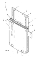
- Figure 1 shows an axonometric view of the accessory 1 according to the invention 1. It is formed essentially of two shell parts attached to each other, a rear cover 2 and a front cover 3. These parts 2 and 3 are suitably attached to each other, for instance using screws or, for example, by gluing. As Figure 1 clearly shows, the rear cover 2 is longer than the front cover 3, so that in use the upper part of it forms an essentially plate-like protrusion, in which suitable means can be made, for instance for attaching it to work clothes. A shown in the figure, these means are holes 4, through which the accessory 1 can be attached, for example, by screws to a plastic-backed material in the vicinity of the breast pocket of an overall.
- the rear cover 2 is clearly longer than the front cover.
- the extension is marked with the reference number 2'.
- the extension has several purposes. One purpose is to create a suitable base as a location for instructions and diagrams. A second purpose is to protect the user, in cases in which the accessory according to the invention is placed on a piece of clothing that is close to the user's skin. Thus, for example, putting a screwdriver or sheath knife in place will not cause the danger that the user may accidentally stab himself.
- a third important advantage of the said extension is that, if the accessory is placed, for example, in the vicinity of, for instance a breast pocket, the attachment point will be higher up in clothing, due to the extension, so that, when stooping, the clothing cannot stretch into the field of vision, to interfere with work. As is known, clothes nearer to the shoulders are closer to the user.
- the fitting can be assisted with the aid of the flexible protrusions 5 protruding from the sides of the accessory 1.
- These protrusions which are especially of rubber or a similar material are flexible plate-like protrusions, which, when straight or bent, fit into the inner sides of the pocket and make fitting into the pocket easy and secure.
- protrusions 6 which extend from both sides of the opening are set in the opening between the cover parts, and which can be pin-like, narrow plate shaped, or similar.
- the important fact is that the protrusions 6 are flexible. The intention is that a tool or device pushed between the protrusions 6 will remain in place in such a manner that it cannot fall out. This is achieved by the device being pressed between the flexible protrusions 6.
- the material of the protrusions 6 is such that their friction acting on the device will be sufficient to hold the object in place, even if the accessory 1 turns upside down.
- Figure 1 uses drawing markings to illustrate the location, into which a sheath knife can be pushed in a manner that mostly prevents damage. It is described in the following.
- the spacing pieces 9 of the rear cover can lock into recesses in the front wall and similarly the spacing pieces attached to the front cover can lock into recesses at a free distance in the rear cover.
- the simplest being to increase the thickness of the material.
- the essential purpose of a sturdy spacing piece is, in exceptional cases, to prevent the blade of the knife from turning to the side and causing a danger there.
- a second safety factor in the sheath-knife compartment of the accessory according to the invention is that, by ensuring at the location of the blade of the knife that the blade cannot also accidently turn, for instance through the rear cover of the accessory in a breast pocket and into the user's chest, thus ensuring that damage is prevented or minimized. Thus, this is ensured by making a step or reinforcement 10 in the rear cover 2 at the location of the knife blade.
- the first factor relating to safety using the said step 10 is that, thanks to it, the knife blade turns to a slightly slanting attitude away from the rear cover 2, in which case its natural attitude will be such that rotation directed to the knife hilt cannot bring the point of the knife towards the chest of the person using the accessory.
- the accessory according to the invention can be made using the dimension ratios shown, but a wider or a narrower shape is also possible.
- the vertical dimension can be selected in such a way that the tools according to the intended use are taken into account, in such a way that the average lengths of the tools will be appropriately taken into account.
- many other variations are also possible.
Landscapes
- Engineering & Computer Science (AREA)
- Mechanical Engineering (AREA)
- Knives (AREA)
- Packaging Of Annular Or Rod-Shaped Articles, Wearing Apparel, Cassettes, Or The Like (AREA)
- Professional, Industrial, Or Sporting Protective Garments (AREA)
Abstract
Description
- The present invention relates to an accessory for holding goods. More specifically, the matter is particularly, though not solely, of an accessory intended to hold small tools used in building work.
- During building and renovation work, a numerous group of different types of tool are required. An electrician will need many different kinds of screwdriver, current testers, and similar, but also particularly a sheath knife. A sheath knife is also a necessary and even essential tool for professionals and amateurs in many other trades.
- The working environment is seldom such that all work required can be performed while standing. Thus, in nearly all work goods will need to be picked up from floor level, bending in one direction and another and also making other movements deviating from the standing position. This creates the danger that the tools that are hanging loops from clothing, or which, for example in the case of a sheath knife, have been placed in a sheath, will detatch from their storage location and fall. This can cause even a serious danger to bystanders. For example, a sheath knife can fall and strike a bystander.
- Attempts have been made to place tools in various types of holder, some of which are intended to be kept on a desk or similar surface, but some of which are intended to be attached to, for example, a shirt pocket. Such a holder is disclosed in
US patent 3056180 , which presents a case, which is placed in a shirt pocket, where it is held in place by a flexible clip. Pens and similar are held in place by a material, into which the pens are pushed. - A device of the kind described above is also disclosed in
US patent 4189048 , in which pens are held in place with the aid of plastic tongues. - The present invention is intended to create an accessory, by means of which the drawbacks of the prior art can be avoided and which is particularly suitable for use in work that requires a sheath knife.
- The aforementioned and other advantages and benefits of the present invention are achieved by means of an accessory, the characterizing features of which are stated in the accompanying Claims.
- In the following, the invention is described in greater detail with reference to the accompanying schematic drawings, which show one practicable and well-regarded embodiment of the invention.
-
Figure 1 shows an axonometric view of the accessory according to the invention; -
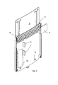
Figure 2 shows the accessory according toFigure 1 with the front cover removed; -
Figure 3 shows, for its part, a view of the accessory according to the invention, seen from straight in front and in part transparent; and -
Figure 4 shows a cross-sectional view A-A of the former view. - Thus,
Figure 1 shows an axonometric view of theaccessory 1 according to theinvention 1. It is formed essentially of two shell parts attached to each other, arear cover 2 and afront cover 3. Theseparts Figure 1 clearly shows, therear cover 2 is longer than thefront cover 3, so that in use the upper part of it forms an essentially plate-like protrusion, in which suitable means can be made, for instance for attaching it to work clothes. A shown in the figure, these means areholes 4, through which theaccessory 1 can be attached, for example, by screws to a plastic-backed material in the vicinity of the breast pocket of an overall. - In the embodiment shown, the
rear cover 2 is clearly longer than the front cover. The extension is marked with the reference number 2'. The extension has several purposes. One purpose is to create a suitable base as a location for instructions and diagrams. A second purpose is to protect the user, in cases in which the accessory according to the invention is placed on a piece of clothing that is close to the user's skin. Thus, for example, putting a screwdriver or sheath knife in place will not cause the danger that the user may accidentally stab himself. A third important advantage of the said extension is that, if the accessory is placed, for example, in the vicinity of, for instance a breast pocket, the attachment point will be higher up in clothing, due to the extension, so that, when stooping, the clothing cannot stretch into the field of vision, to interfere with work. As is known, clothes nearer to the shoulders are closer to the user. - If it is wished to place the accessory according to the invention inside the breast pocket of an overall, the fitting can be assisted with the aid of the
flexible protrusions 5 protruding from the sides of theaccessory 1. These protrusions, which are especially of rubber or a similar material are flexible plate-like protrusions, which, when straight or bent, fit into the inner sides of the pocket and make fitting into the pocket easy and secure. - In use,
flexible protrusions 6, which extend from both sides of the opening are set in the opening between the cover parts, and which can be pin-like, narrow plate shaped, or similar. The important fact is that theprotrusions 6 are flexible. The intention is that a tool or device pushed between theprotrusions 6 will remain in place in such a manner that it cannot fall out. This is achieved by the device being pressed between theflexible protrusions 6. The material of theprotrusions 6 is such that their friction acting on the device will be sufficient to hold the object in place, even if theaccessory 1 turns upside down. - It can also be seen from
Figure 1 that, in the use of theaccessory 1 according to the invention, particular attention has been paid to the location of one device that often causes accidents according to the prior art, i.e. the sheath knife. Thus, in the accessory according to the invention, the sheath knife has its own compartment. -
Figure 1 uses drawing markings to illustrate the location, into which a sheath knife can be pushed in a manner that mostly prevents damage. It is described in the following. - In
Figure 2 , thefront cover 3 of the accessory according to the invention has been removed, thus revealing the interior of the accessory. As can be seen, there areholes 8 near to the lower edge of the accessory, for a screw or similar attachment. Access to them is through the slightlylarger holes 7 in thefront cover 3. Thus, if it is wished to attach the accessory, for instance to work clothes, this can be done suitably by utilizing theholes - It was stated above that the location of the sheath knife has a special position in the accessory according to the invention. Thus, it can be clearly seen from
Figure 2 , that the part of the accessory reserved for the sheath knife is separated from the rest of the compartment by aspacing piece 9. Such spacing pieces can be in both therear cover 2 and thefront cover 3, in which case they will mainly take up alternating positions in sequential order, to form a sturdy partition. - If it is wished to increase sturdiness, the
spacing pieces 9 of the rear cover can lock into recesses in the front wall and similarly the spacing pieces attached to the front cover can lock into recesses at a free distance in the rear cover. Of course, there are many other ways in which to achieve sturdiness, the simplest being to increase the thickness of the material. The essential purpose of a sturdy spacing piece is, in exceptional cases, to prevent the blade of the knife from turning to the side and causing a danger there. - A second safety factor in the sheath-knife compartment of the accessory according to the invention is that, by ensuring at the location of the blade of the knife that the blade cannot also accidently turn, for instance through the rear cover of the accessory in a breast pocket and into the user's chest, thus ensuring that damage is prevented or minimized. Thus, this is ensured by making a step or
reinforcement 10 in therear cover 2 at the location of the knife blade. - The first factor relating to safety using the said
step 10 is that, thanks to it, the knife blade turns to a slightly slanting attitude away from therear cover 2, in which case its natural attitude will be such that rotation directed to the knife hilt cannot bring the point of the knife towards the chest of the person using the accessory. -
Figure 3 shows the accessory according to the invention as 'transparent' while -
Figure 4 , for its part, shows a cross-section A-A ofFigure 3 . - The embodiment shown by
Figures 3 and 4 will be clear on the basis of the descriptions and marked reference numbers ofFigures 1 and2 . - The well-regarded embodiment of the invention described above can be varied in many ways, without nevertheless deviating from the basic idea of the invention and the scope of the protection of the accompanying Claims. It goes without saying, that the shapes of the accessory can be varied in many ways to change its appearance. The surfaces of the accessory can be used as a base for various instructions, or even advertisements. The slightly curved cross-sectional shape shown in
Figure 4 can equally well be straight. - The accessory according to the invention can be made using the dimension ratios shown, but a wider or a narrower shape is also possible. The vertical dimension can be selected in such a way that the tools according to the intended use are taken into account, in such a way that the average lengths of the tools will be appropriately taken into account. In addition to the variations described above, many other variations are also possible.
Claims (9)
- Accessory (1) for holding goods, comprising a case-like structure (2, 3), in which there are holders (6) for holding tools and similar placed in it, characterized in that, in the accessory there is a separate compartment, separated by spacing pieces (9) for a cutting weapon, such as a sheath knife, on the bottom of which is a protrusion (10) that turns the blade of the knife away from the rear cover (2).
- Accessory according to Claim 1, characterized in that the spacing pieces (9) are formed of partition parts, in an alternating sequence, protruding from the front (3) and rear (2) covers.
- Accessory according to Claim 1, characterized in that the protrusion (10) is a thickening in the rear cover (2).
- Accessory according to Claim 1, characterized in that the protrusion (10) is a fold in the rear cover (2).
- Accessory according to any of the above Claims, characterized in that, in the accessory (1) are flexible protrusions (5) protruding towards its sides.
- Accessory according to Claim 5, characterized in that the flexible protrusions (5) are of rubber or a rubber-like material.
- Accessory according to any of the above Claims, characterized in that the accessory is manufactured from an essentially sheet-like plastic material.
- Accessory according to any of the above Claims, characterized in that the holders (6) are essentially pin-like and of a flexible material.
- Accessory according to any of the above Claims, characterized in that, in the accessory's upper part, the rear cover (2) is clearly longer than the front cover (2').
Applications Claiming Priority (1)
| Application Number | Priority Date | Filing Date | Title |
|---|---|---|---|
| FI20105597A FI123792B (en) | 2010-05-27 | 2010-05-27 | Tools for retaining articles |
Publications (2)
| Publication Number | Publication Date |
|---|---|
| EP2390063A2 true EP2390063A2 (en) | 2011-11-30 |
| EP2390063A3 EP2390063A3 (en) | 2014-07-30 |
Family
ID=42234374
Family Applications (1)
| Application Number | Title | Priority Date | Filing Date |
|---|---|---|---|
| EP11166725.9A Withdrawn EP2390063A3 (en) | 2010-05-27 | 2011-05-19 | Accessory for holding goods |
Country Status (3)
| Country | Link |
|---|---|
| US (2) | US20110290690A1 (en) |
| EP (1) | EP2390063A3 (en) |
| FI (1) | FI123792B (en) |
Families Citing this family (1)
| Publication number | Priority date | Publication date | Assignee | Title |
|---|---|---|---|---|
| US9033148B2 (en) * | 2011-07-28 | 2015-05-19 | Philip P. Adams | Knife sheath |
Citations (2)
| Publication number | Priority date | Publication date | Assignee | Title |
|---|---|---|---|---|
| US3056180A (en) | 1958-09-25 | 1962-10-02 | Gink Arnold Harry | Gripping device for pencil and the like |
| US4189048A (en) | 1978-02-22 | 1980-02-19 | Raymond Gaillard | Article holder |
Family Cites Families (13)
| Publication number | Priority date | Publication date | Assignee | Title |
|---|---|---|---|---|
| US2424302A (en) * | 1946-03-18 | 1947-07-22 | Kyle J Brickey | Scabbard |
| US2522213A (en) * | 1946-05-17 | 1950-09-12 | Doniger Sundel | Tool kit |
| IT8553139U1 (en) * | 1985-03-18 | 1986-09-18 | Marietti Coltelleria Spa | KNIFE HOLDER DEVICE CAN ALSO BE USED AS PACKAGING. |
| DE9203049U1 (en) * | 1992-01-08 | 1992-05-07 | ITEC Ingenieurbüro für Hygiene und Lebensmitteltechnik GmbH, 4720 Beckum | Knife holder |
| DE4320592A1 (en) * | 1993-06-22 | 1995-01-12 | Parat Werk Schoenenbach Gmbh | Holding device for tools, instruments or the like. |
| US5490607A (en) * | 1994-12-19 | 1996-02-13 | Hsieh; Wen-Hsiung | Knife holder |
| US5738228A (en) * | 1996-05-24 | 1998-04-14 | Bittinger; Andrew H. | Object holder |
| USD403150S (en) * | 1998-02-04 | 1998-12-29 | Sinclair & Rush, Inc. | Tool holster |
| USD433229S (en) * | 2000-02-25 | 2000-11-07 | Leonard C Harker | Belt mounted tool holder |
| US7011212B2 (en) * | 2002-08-07 | 2006-03-14 | Beza, L.P. | Tool kits |
| US7290656B1 (en) * | 2004-03-10 | 2007-11-06 | Raymond Crawford | Sheetrock knife and holder apparatus |
| USD560906S1 (en) * | 2007-01-05 | 2008-02-05 | Chi-Fen Meng | Toolbox |
| US8028872B2 (en) * | 2007-10-12 | 2011-10-04 | Omniquest Ltd. | Utility pocket with magnetic closure |
-
2010
- 2010-05-27 FI FI20105597A patent/FI123792B/en active IP Right Grant
-
2011
- 2011-05-17 US US13/109,029 patent/US20110290690A1/en not_active Abandoned
- 2011-05-19 EP EP11166725.9A patent/EP2390063A3/en not_active Withdrawn
-
2013
- 2013-07-10 US US29/460,320 patent/USD710090S1/en active Active
Patent Citations (2)
| Publication number | Priority date | Publication date | Assignee | Title |
|---|---|---|---|---|
| US3056180A (en) | 1958-09-25 | 1962-10-02 | Gink Arnold Harry | Gripping device for pencil and the like |
| US4189048A (en) | 1978-02-22 | 1980-02-19 | Raymond Gaillard | Article holder |
Also Published As
| Publication number | Publication date |
|---|---|
| FI123792B (en) | 2013-10-31 |
| EP2390063A3 (en) | 2014-07-30 |
| US20110290690A1 (en) | 2011-12-01 |
| FI20105597L (en) | 2011-11-28 |
| USD710090S1 (en) | 2014-08-05 |
| FI20105597A0 (en) | 2010-05-27 |
Similar Documents
| Publication | Publication Date | Title |
|---|---|---|
| USD832641S1 (en) | Blender | |
| US9144291B2 (en) | Tool holder and the method of making thereof | |
| USD823239S1 (en) | Combination battery, charger and cables for electronic equipment | |
| USD702239S1 (en) | Thin client housing | |
| USD822379S1 (en) | Holder for portable electronic device | |
| US8819954B1 (en) | Tape measure assembly | |
| USD765663S1 (en) | Protective cover for a portable electronic device | |
| US9126328B2 (en) | Tool holder unit | |
| US6325345B1 (en) | Panel wall hanger and file holder | |
| CA159893S (en) | Usb ac charger adaptor with built-in rechargeable battery | |
| USD813535S1 (en) | Document window pouch | |
| US10173334B2 (en) | Magnetic utility knife and holder | |
| CA175465S (en) | Painter`s utility knife | |
| USD836143S1 (en) | Cutting insert holder | |
| KR20120003484U (en) | Electric drill with a hook tool hanger | |
| USD821177S1 (en) | Portable lock housing | |
| USD758498S1 (en) | Portable casino slot card organizer | |
| US20110290690A1 (en) | Accessory for holding goods | |
| USD832097S1 (en) | Holder for ties and accessories | |
| USD822603S1 (en) | Battery cover | |
| US9573270B2 (en) | Tool holder | |
| WO2014063171A1 (en) | Combination soap container and handle | |
| USD891413S1 (en) | Cell phone case for orienteering and ground navigation | |
| US20070023471A1 (en) | Trowel holder | |
| USD897942S1 (en) | Electric power converter |
Legal Events
| Date | Code | Title | Description |
|---|---|---|---|
| AK | Designated contracting states |
Kind code of ref document: A2 Designated state(s): AL AT BE BG CH CY CZ DE DK EE ES FI FR GB GR HR HU IE IS IT LI LT LU LV MC MK MT NL NO PL PT RO RS SE SI SK SM TR |
|
| AX | Request for extension of the european patent |
Extension state: BA ME |
|
| PUAI | Public reference made under article 153(3) epc to a published international application that has entered the european phase |
Free format text: ORIGINAL CODE: 0009012 |
|
| PUAL | Search report despatched |
Free format text: ORIGINAL CODE: 0009013 |
|
| AK | Designated contracting states |
Kind code of ref document: A3 Designated state(s): AL AT BE BG CH CY CZ DE DK EE ES FI FR GB GR HR HU IE IS IT LI LT LU LV MC MK MT NL NO PL PT RO RS SE SI SK SM TR |
|
| AX | Request for extension of the european patent |
Extension state: BA ME |
|
| RIC1 | Information provided on ipc code assigned before grant |
Ipc: B25H 3/04 20060101AFI20140620BHEP |
|
| STAA | Information on the status of an ep patent application or granted ep patent |
Free format text: STATUS: THE APPLICATION IS DEEMED TO BE WITHDRAWN |
|
| 18D | Application deemed to be withdrawn |
Effective date: 20150131 |