EP2390024A2 - Ceramic core tapered trip strips - Google Patents
Ceramic core tapered trip strips Download PDFInfo
- Publication number
- EP2390024A2 EP2390024A2 EP11166387A EP11166387A EP2390024A2 EP 2390024 A2 EP2390024 A2 EP 2390024A2 EP 11166387 A EP11166387 A EP 11166387A EP 11166387 A EP11166387 A EP 11166387A EP 2390024 A2 EP2390024 A2 EP 2390024A2
- Authority
- EP
- European Patent Office
- Prior art keywords
- core
- slot
- outer dimension
- insert
- trip
- Prior art date
- Legal status (The legal status is an assumption and is not a legal conclusion. Google has not performed a legal analysis and makes no representation as to the accuracy of the status listed.)
- Granted
Links
- 239000000919 ceramic Substances 0.000 title description 26
- 229910010293 ceramic material Inorganic materials 0.000 claims abstract description 12
- 238000001816 cooling Methods 0.000 claims description 8
- 230000013011 mating Effects 0.000 claims description 2
- 239000000463 material Substances 0.000 description 4
- 238000004519 manufacturing process Methods 0.000 description 2
- 239000003870 refractory metal Substances 0.000 description 2
- 238000004026 adhesive bonding Methods 0.000 description 1
- 230000001419 dependent effect Effects 0.000 description 1
- 238000013461 design Methods 0.000 description 1
- 238000010438 heat treatment Methods 0.000 description 1
- 238000005495 investment casting Methods 0.000 description 1
- 238000002844 melting Methods 0.000 description 1
- 230000008018 melting Effects 0.000 description 1
- 239000002184 metal Substances 0.000 description 1
- 238000000034 method Methods 0.000 description 1
- 238000012986 modification Methods 0.000 description 1
- 230000004048 modification Effects 0.000 description 1
- 238000012545 processing Methods 0.000 description 1
- 238000012546 transfer Methods 0.000 description 1
Images

Classifications
-
- B—PERFORMING OPERATIONS; TRANSPORTING
- B22—CASTING; POWDER METALLURGY
- B22C—FOUNDRY MOULDING
- B22C9/00—Moulds or cores; Moulding processes
- B22C9/10—Cores; Manufacture or installation of cores
-
- F—MECHANICAL ENGINEERING; LIGHTING; HEATING; WEAPONS; BLASTING
- F01—MACHINES OR ENGINES IN GENERAL; ENGINE PLANTS IN GENERAL; STEAM ENGINES
- F01D—NON-POSITIVE DISPLACEMENT MACHINES OR ENGINES, e.g. STEAM TURBINES
- F01D5/00—Blades; Blade-carrying members; Heating, heat-insulating, cooling or antivibration means on the blades or the members
- F01D5/12—Blades
- F01D5/14—Form or construction
- F01D5/18—Hollow blades, i.e. blades with cooling or heating channels or cavities; Heating, heat-insulating or cooling means on blades
- F01D5/187—Convection cooling
-
- B—PERFORMING OPERATIONS; TRANSPORTING
- B22—CASTING; POWDER METALLURGY
- B22C—FOUNDRY MOULDING
- B22C7/00—Patterns; Manufacture thereof so far as not provided for in other classes
- B22C7/06—Core boxes
-
- B—PERFORMING OPERATIONS; TRANSPORTING
- B22—CASTING; POWDER METALLURGY
- B22C—FOUNDRY MOULDING
- B22C9/00—Moulds or cores; Moulding processes
- B22C9/10—Cores; Manufacture or installation of cores
- B22C9/103—Multipart cores
-
- F—MECHANICAL ENGINEERING; LIGHTING; HEATING; WEAPONS; BLASTING
- F05—INDEXING SCHEMES RELATING TO ENGINES OR PUMPS IN VARIOUS SUBCLASSES OF CLASSES F01-F04
- F05D—INDEXING SCHEME FOR ASPECTS RELATING TO NON-POSITIVE-DISPLACEMENT MACHINES OR ENGINES, GAS-TURBINES OR JET-PROPULSION PLANTS
- F05D2230/00—Manufacture
- F05D2230/20—Manufacture essentially without removing material
- F05D2230/21—Manufacture essentially without removing material by casting
-
- F—MECHANICAL ENGINEERING; LIGHTING; HEATING; WEAPONS; BLASTING
- F05—INDEXING SCHEMES RELATING TO ENGINES OR PUMPS IN VARIOUS SUBCLASSES OF CLASSES F01-F04
- F05D—INDEXING SCHEME FOR ASPECTS RELATING TO NON-POSITIVE-DISPLACEMENT MACHINES OR ENGINES, GAS-TURBINES OR JET-PROPULSION PLANTS
- F05D2240/00—Components
- F05D2240/10—Stators
- F05D2240/12—Fluid guiding means, e.g. vanes
- F05D2240/122—Fluid guiding means, e.g. vanes related to the trailing edge of a stator vane
-
- F—MECHANICAL ENGINEERING; LIGHTING; HEATING; WEAPONS; BLASTING
- F05—INDEXING SCHEMES RELATING TO ENGINES OR PUMPS IN VARIOUS SUBCLASSES OF CLASSES F01-F04
- F05D—INDEXING SCHEME FOR ASPECTS RELATING TO NON-POSITIVE-DISPLACEMENT MACHINES OR ENGINES, GAS-TURBINES OR JET-PROPULSION PLANTS
- F05D2240/00—Components
- F05D2240/20—Rotors
- F05D2240/30—Characteristics of rotor blades, i.e. of any element transforming dynamic fluid energy to or from rotational energy and being attached to a rotor
- F05D2240/304—Characteristics of rotor blades, i.e. of any element transforming dynamic fluid energy to or from rotational energy and being attached to a rotor related to the trailing edge of a rotor blade
-
- F—MECHANICAL ENGINEERING; LIGHTING; HEATING; WEAPONS; BLASTING
- F05—INDEXING SCHEMES RELATING TO ENGINES OR PUMPS IN VARIOUS SUBCLASSES OF CLASSES F01-F04
- F05D—INDEXING SCHEME FOR ASPECTS RELATING TO NON-POSITIVE-DISPLACEMENT MACHINES OR ENGINES, GAS-TURBINES OR JET-PROPULSION PLANTS
- F05D2250/00—Geometry
- F05D2250/20—Three-dimensional
- F05D2250/29—Three-dimensional machined; miscellaneous
- F05D2250/292—Three-dimensional machined; miscellaneous tapered
-
- F—MECHANICAL ENGINEERING; LIGHTING; HEATING; WEAPONS; BLASTING
- F05—INDEXING SCHEMES RELATING TO ENGINES OR PUMPS IN VARIOUS SUBCLASSES OF CLASSES F01-F04
- F05D—INDEXING SCHEME FOR ASPECTS RELATING TO NON-POSITIVE-DISPLACEMENT MACHINES OR ENGINES, GAS-TURBINES OR JET-PROPULSION PLANTS
- F05D2260/00—Function
- F05D2260/20—Heat transfer, e.g. cooling
- F05D2260/221—Improvement of heat transfer
- F05D2260/2214—Improvement of heat transfer by increasing the heat transfer surface
- F05D2260/22141—Improvement of heat transfer by increasing the heat transfer surface using fins or ribs
Definitions
- Turbine airfoils for example, use internal cores that form hollow passages within the airfoils. In high heat load applications, trip strips may be used within these passages to further enhance convective cooling.
- a ceramic material it is typical in the art, for a ceramic material to be injected into a metal die and then fired to form desired core passages of a turbine airfoil. Slots are built into the die into which a RMC (Refractory Metal Core) is inserted. The RMC is stamped or cut out and then put into form dies to achieve the desired 3D shapes. The RMC is then attached into the slots in the ceramic core. At this point, the sacrificial die is prepared for further processing such as a lost wax process, investment casting or the like.
- RMC Refractory Metal Core
- a core for creating an airfoil has body made from a ceramic material.
- the body has an outer dimension, a slot extending through the outer dimension and into the body for receiving an insert, the slot disposed at an angle to the outer dimension, and a trip strip having a first portion disposed in the outer dimension.
- the first portion is in register with the slot wherein a constant dimension is maintained between the first portion and the slot along a length of the slot and wherein said first portion tapers towards said outer dimension to facilitate the manufacturability of the ceramic core.
- a core die for creating a core has a first section, a second section mating with the first section, and an insert for creating a slot.
- the first section and the second section define a body having an outer dimension, the insert disposed at an angle to the outer dimension, and trip strips having a first portion disposed in the second section, the first portion in register with the insert wherein a constant dimension such as minimum thickness is maintained between the first portion and the insert along a length of the insert and wherein said first portion tapers towards said outer dimension.
- an airfoil has a body having an inner passageway for cooling the body, trip strips disposed within the inner passageway, the trip strips tapering.
- FIG 1 shows a sacrificial core assembly 10 used in making a turbine blade 130 (see Figure 5 ).
- the sacrificial core assembly 10 has a ceramic core 15 and an RMC 20, also known as a Refractory Metal Core, that acts as an insert and is attached into a slot 25 (see the ceramic core 15 shown in die 90 in Fig. 2 and isolated in Fig. 3 ) in the ceramic core 15.
- the ceramic core 15 has a plurality of trip strips 65 that provide enhanced heat transfer to cool a turbine blade 130 (see Fig 5 ).
- the ceramic core 15 has an outer dimension including a suction side 35, a pressure side 40, a trailing edge 45, a leading edge 50 and slot 25 (see Figs. 2 and 3 ) for RMC 20 to be inserted.
- the RMC may be secured in the slot in several ways including gluing or mechanical means, such as clips or the like (not shown).
- a plurality of trip strips 65 extend along a length of the suction side 35 of the ceramic core 15.
- the trip strips 65 are shown adjacent the trailing edge 45 of the suction side 35 but may be placed anywhere heating loads in or on the turbine blade 130 make additional cooling desirable.
- trip strips 65 placed towards the trailing edge 45 of the ceramic core 15, while still allowing for adequate dimension D, such as thickness or depth or the like, from the slot 25 to maintain manufacturability as will be discussed herein. Without the placement of the tapered trip strip portion 70, trip strip coverage is reduced to accommodate minimum ceramic core thickness requirements for manufacturing and required cooling may not be provided.
- Trip strips 65 may be of any size, shape and configuration (straight, chevron - see Fig. 4 , etc.) as may be required to provide cooling. Although this disclosure shows the trip strips 65 on the suction side 35, all the same concepts could be used with trip strips on either the suction side 35 or pressure side 40, depending on the cooling requirements of the particular part.
- Each trip strip 65 has a portion 75, which is elongated and has a rectangular cross-section.
- the portion 75 which may have an angled part 75A attached thereto to form a chevron, is attached to a tapered portion 70.
- Both the portion 75 and tapered portion 70 are disposed on a wall 80, which is the same surface on a finished blade (see Fig. 5 ).
- Each tapered portion 70 tapers towards the wall portion 80 from the portion 75A.
- the tops 81 and 81A are in plane but the top 70A of portion 70 tapers downwardly out of plane with tops 81 and 81 A of portions 75 and 75A thereby creating taper portion 70.
- tapered portion 70 may be disposed on any portion of the trip strip 65 to accommodate an area 125 between the slot 25 and the wall 70A (see Fig.2 ) as will be discussed hereinbelow and as may be required by a particular design. Taper portion 70 also need not be attached to a portion 75 to be functional herein. Similarly, both the taper portion 70 and the portion 75 may have other cross-sectional dimensions and such other shapes are contemplated herein.
- the ceramic core 15 is shown along lines 2-2.
- the ceramic core 15 is formed in a core die 90 having a first half 95, a second half 100 and a manufacturing insert 105 that is removably attached to the respective core die 90 halves 95 and 100 or sections, as is known in the art.
- the ceramic core 15 shows portions 75A of the trip strips 65 and the tapered portions 70 of the trip strips 65.
- the trip strips 65 come out of the core die 90 as shown in Fig 3 .
- the core die 90 includes the insert 105 and ceramic material 120 is inserted into the core die 90.
- the ceramic material flows to all areas of the core die 90, however, areas in which the ceramic material 120 flows must have a dimension such as minimum thickness to allow the material to fill the core die 90 as well as provide strength in the finished ceramic core.
- the area 125 between the tapered portion 70 of the trip strip 65 and the slot 105 has a thickness D, which is dependent on the type of ceramic material used, to allow the ceramic material 120 to fill the area 125 to the trailing edge 45. It should be noted that the dimension D may vary for given ceramic materials.
- the trip strip portion 70 may be tapered while maintaining the thickness D to allow for the tapered portion 70 to extend closer to trailing edges of the ceramic core 15. If the thickness D is not maintained, the ceramic material 120 may not flow to the trailing edge 45 or breakage in the finished ceramic core may be experienced.
- the trip strip portion 70 tapers in register with the shape of the slot 25 so that the thickness D is maintained in area 125.
- the ceramic core 15 is removed from the core die 90 and the insert 105 is removed from the ceramic core 15.
- the RMC 20 is attached into slot 25.
- the ceramic core 15 and the RMC are sacrificed, as is known in the art, to make the turbine blade 130 shown partially in Figure 5 .
- the RMC 20 and ceramic core 15 become shaped opening 135 (of the finished part - see fig. 5 ) and the trip strips 65, including the tapered portion 70 and portions 75 are distributed along the outer edges of the opening 135. Because of the tapered portions 70 of surface the trip strips 65, the trip strips 65 can now be distributed to a greater area of the shaped opening 135.
- trip strips 65 can be placed anywhere within the turbine blade 130. However, when forming the ceramic core 15, there must be enough room in the core die 90 to allow for the manufacturability of the ceramic core 15 and a certain dimension such as minimum thickness D must be allowed. Prior art cores have not been designed to accommodate trip strips 65 where they would be most useful. This disclosure allows for the additional of trip strips 65 in areas 135 not previous thought as suitable for trip strips.
Landscapes
- Engineering & Computer Science (AREA)
- Mechanical Engineering (AREA)
- General Engineering & Computer Science (AREA)
- Turbine Rotor Nozzle Sealing (AREA)
- Molds, Cores, And Manufacturing Methods Thereof (AREA)
Abstract
Description
- Materials used in the turbine section of a gas turbine engine may be subjected to temperatures that are above the melting point of those materials. To operate under such high temperatures, the parts using those materials must be internally cooled. Turbine airfoils, for example, use internal cores that form hollow passages within the airfoils. In high heat load applications, trip strips may be used within these passages to further enhance convective cooling.
- It is typical in the art, for a ceramic material to be injected into a metal die and then fired to form desired core passages of a turbine airfoil. Slots are built into the die into which a RMC (Refractory Metal Core) is inserted. The RMC is stamped or cut out and then put into form dies to achieve the desired 3D shapes. The RMC is then attached into the slots in the ceramic core. At this point, the sacrificial die is prepared for further processing such as a lost wax process, investment casting or the like.
- According to an exemplar, a core for creating an airfoil has body made from a ceramic material. The body has an outer dimension, a slot extending through the outer dimension and into the body for receiving an insert, the slot disposed at an angle to the outer dimension, and a trip strip having a first portion disposed in the outer dimension. The first portion is in register with the slot wherein a constant dimension is maintained between the first portion and the slot along a length of the slot and wherein said first portion tapers towards said outer dimension to facilitate the manufacturability of the ceramic core.
- According to a further exemplar, a core die for creating a core has a first section, a second section mating with the first section, and an insert for creating a slot. The first section and the second section define a body having an outer dimension, the insert disposed at an angle to the outer dimension, and trip strips having a first portion disposed in the second section, the first portion in register with the insert wherein a constant dimension such as minimum thickness is maintained between the first portion and the insert along a length of the insert and wherein said first portion tapers towards said outer dimension.
- According to a further exemplar, an airfoil has a body having an inner passageway for cooling the body, trip strips disposed within the inner passageway, the trip strips tapering.
- These and other features of the present invention can be best understood from the following specification and drawings, the following of which is a brief description.
-
-
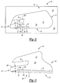
Figure 1 is a side, perspective view of a ceramic core including an RMC insert. -
Figure 2 is a cut-away view of the core ofFigure 1 , taken along the line 2-2, shown in a ceramic core mold. -
Figure 3 is a cut-away view of the core ofFigure 1 taken along the line 3-3. -
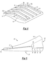
Figure 4 is a partial view of the core die, which is a negative of the core. -
Figure 5 is a partial, cross-sectional view of a turbine blade made from the ceramic core and RMC insert ofFigure 1 . -
Figure 1 shows asacrificial core assembly 10 used in making a turbine blade 130 (seeFigure 5 ). Thesacrificial core assembly 10 has aceramic core 15 and anRMC 20, also known as a Refractory Metal Core, that acts as an insert and is attached into a slot 25 (see theceramic core 15 shown in die 90 inFig. 2 and isolated inFig. 3 ) in theceramic core 15. Theceramic core 15 has a plurality oftrip strips 65 that provide enhanced heat transfer to cool a turbine blade 130 (seeFig 5 ). Theceramic core 15 has an outer dimension including asuction side 35, apressure side 40, atrailing edge 45, a leadingedge 50 and slot 25 (seeFigs. 2 and 3 ) forRMC 20 to be inserted. The RMC may be secured in the slot in several ways including gluing or mechanical means, such as clips or the like (not shown). - Referring to
Figures 2 and 3 , a plurality oftrip strips 65 extend along a length of thesuction side 35 of theceramic core 15. Thetrip strips 65 are shown adjacent thetrailing edge 45 of thesuction side 35 but may be placed anywhere heating loads in or on theturbine blade 130 make additional cooling desirable. - This description shows
trip strips 65 placed towards thetrailing edge 45 of theceramic core 15, while still allowing for adequate dimension D, such as thickness or depth or the like, from theslot 25 to maintain manufacturability as will be discussed herein. Without the placement of the taperedtrip strip portion 70, trip strip coverage is reduced to accommodate minimum ceramic core thickness requirements for manufacturing and required cooling may not be provided.Trip strips 65 may be of any size, shape and configuration (straight, chevron - seeFig. 4 , etc.) as may be required to provide cooling. Although this disclosure shows thetrip strips 65 on thesuction side 35, all the same concepts could be used with trip strips on either thesuction side 35 orpressure side 40, depending on the cooling requirements of the particular part. - Referring now to
Figure 4 , the negative features to producetrips strips 65 of acore die 90 are shown. Eachtrip strip 65 has aportion 75, which is elongated and has a rectangular cross-section. Theportion 75, which may have anangled part 75A attached thereto to form a chevron, is attached to atapered portion 70. Both theportion 75 andtapered portion 70 are disposed on awall 80, which is the same surface on a finished blade (seeFig. 5 ). Eachtapered portion 70 tapers towards thewall portion 80 from theportion 75A. Thetops portion 70 tapers downwardly out of plane withtops portions taper portion 70. One of ordinary skill in the art will recognize that thetapered portion 70 may be disposed on any portion of thetrip strip 65 to accommodate anarea 125 between theslot 25 and thewall 70A (seeFig.2 ) as will be discussed hereinbelow and as may be required by a particular design.Taper portion 70 also need not be attached to aportion 75 to be functional herein. Similarly, both thetaper portion 70 and theportion 75 may have other cross-sectional dimensions and such other shapes are contemplated herein. - Referring now to
Figure 2 and thecore die 90 shown inFigure 4 , theceramic core 15 is shown along lines 2-2. Theceramic core 15 is formed in acore die 90 having afirst half 95, asecond half 100 and amanufacturing insert 105 that is removably attached to therespective core die 90halves ceramic core 15 showsportions 75A of thetrip strips 65 and thetapered portions 70 of thetrip strips 65. Thetrip strips 65 come out of thecore die 90 as shown inFig 3 . - Referring now to
Figure 2 , thecore die 90 includes theinsert 105 andceramic material 120 is inserted into thecore die 90. The ceramic material flows to all areas of thecore die 90, however, areas in which theceramic material 120 flows must have a dimension such as minimum thickness to allow the material to fill thecore die 90 as well as provide strength in the finished ceramic core. For instance thearea 125 between thetapered portion 70 of thetrip strip 65 and theslot 105 has a thickness D, which is dependent on the type of ceramic material used, to allow theceramic material 120 to fill thearea 125 to thetrailing edge 45. It should be noted that the dimension D may vary for given ceramic materials. - By recognizing the need for a thickness D, the
trip strip portion 70 may be tapered while maintaining the thickness D to allow for thetapered portion 70 to extend closer to trailing edges of theceramic core 15. If the thickness D is not maintained, theceramic material 120 may not flow to thetrailing edge 45 or breakage in the finished ceramic core may be experienced. Thetrip strip portion 70 tapers in register with the shape of theslot 25 so that the thickness D is maintained inarea 125. - Referring to
Figures 2, 3 and5 , theceramic core 15 is removed from thecore die 90 and theinsert 105 is removed from theceramic core 15. TheRMC 20 is attached intoslot 25. Theceramic core 15 and the RMC are sacrificed, as is known in the art, to make theturbine blade 130 shown partially inFigure 5 . TheRMC 20 andceramic core 15 become shaped opening 135 (of the finished part - seefig. 5 ) and thetrip strips 65, including thetapered portion 70 andportions 75 are distributed along the outer edges of theopening 135. Because of thetapered portions 70 of surface thetrip strips 65, thetrip strips 65 can now be distributed to a greater area of theshaped opening 135. - Typically,
trip strips 65 can be placed anywhere within theturbine blade 130. However, when forming theceramic core 15, there must be enough room in thecore die 90 to allow for the manufacturability of theceramic core 15 and a certain dimension such as minimum thickness D must be allowed. Prior art cores have not been designed to accommodatetrip strips 65 where they would be most useful. This disclosure allows for the additional oftrip strips 65 inareas 135 not previous thought as suitable for trip strips. - Although a combination of features is shown in the illustrated examples, not all of them need to be combined to realize the benefits of various embodiments of this disclosure. In other words, a system designed according to an embodiment of this disclosure will not necessarily include all of the features shown in any one of the Figures or all of the portions schematically shown in the Figures. Moreover, selected features of one example embodiment may be combined with selected features of other example embodiments.
- The preceding description is exemplary rather than limiting in nature. Variations and modifications to the disclosed examples may become apparent to those skilled in the art that do not necessarily depart from the essence of this disclosure. The scope of legal protection given to this disclosure can only be determined by studying the following claims.
Claims (12)
- A core (15) for creating an airfoil, said core having;
a body comprised of a ceramic material having
an outer dimension,
a slot (25) extending through said outer dimension and into said body (15) for receiving an insert (20), said slot (25) disposed at an angle to said outer dimension,
a trip strip (65) having a first portion (70) disposed in said outer dimension, said first portion (70) in register with said slot (25) wherein a minimum dimension (D) is maintained between the first portion (70) and the slot (25) along a length of said slot (25) and wherein said first portion (70) tapers towards said outer dimension. - The core of claim 1 wherein said minimum dimension (D) comprises thickness.
- The core of claim 1 or 2 wherein said first portion (70) and a second portion (75) of said trip strips each have a portion not in plane with each other.
- The core of any preceding claim wherein said first portion (70) is tapered along a portion of the length thereof.
- The core of claim 4 wherein said first portion (70) and a second portion (75) of said trip strip (65) are angled relative to each other.
- A core die (90) for creating an airfoil, said mold having;
a first section (95),
a second section (100) mating with said first section (95),
an insert (105) for creating a slot (25),
wherein said first section (95) and said second section (100) define a body (15) having an outer dimension, said insert (105) disposed at an angle to said outer dimension, and,
a trip strip (65) having a first portion (70) disposed in said second section (100), said first portion (70) in register with said insert (105) wherein a thickness (D) is maintained between the first portion (70) and the insert (105) along a length of said insert (105), wherein said first portion tapers towards said outer dimension and wherein said thickness (D) is filled by the ceramic material between said slot (25) and said first portion (70). - The core die of claim 6 wherein said first portion (70) and a second portion (75) of said trip strips (65) each have a portion not in plane with each other.
- The core die of claim 6 or 7 wherein said first portion (70) is tapered along a portion of the length thereof.
- The core die of claim 8 wherein said first portion (70) and a second portion (75) of said trip strip are angled relative to each other.
- An airfoil (130), said airfoil having;
body having;
an inner passageway for cooling said body,
a trip strip (65) having a first portion (70) disposed within said inner passageway, said first portion (70) tapering into an area (135) requiring increased cooling. - The airfoil of claim 10 wherein said trip strip (65) further comprises;
a second portion (75) disposed at an angle from said first portion (70). - The airfoil of claim 10 wherein said first portion (70) and a second portion (75) of said trip strips (65) are in plane with each other.
Applications Claiming Priority (1)
| Application Number | Priority Date | Filing Date | Title |
|---|---|---|---|
| US12/786,066 US8353329B2 (en) | 2010-05-24 | 2010-05-24 | Ceramic core tapered trip strips |
Publications (3)
| Publication Number | Publication Date |
|---|---|
| EP2390024A2 true EP2390024A2 (en) | 2011-11-30 |
| EP2390024A3 EP2390024A3 (en) | 2013-04-17 |
| EP2390024B1 EP2390024B1 (en) | 2016-08-17 |
Family
ID=44972618
Family Applications (1)
| Application Number | Title | Priority Date | Filing Date |
|---|---|---|---|
| EP11166387.8A Not-in-force EP2390024B1 (en) | 2010-05-24 | 2011-05-17 | Ceramic core tapered trip trips, core die and turbine blade |
Country Status (2)
| Country | Link |
|---|---|
| US (2) | US8353329B2 (en) |
| EP (1) | EP2390024B1 (en) |
Families Citing this family (18)
| Publication number | Priority date | Publication date | Assignee | Title |
|---|---|---|---|---|
| US9388700B2 (en) | 2012-03-16 | 2016-07-12 | United Technologies Corporation | Gas turbine engine airfoil cooling circuit |
| US9296039B2 (en) | 2012-04-24 | 2016-03-29 | United Technologies Corporation | Gas turbine engine airfoil impingement cooling |
| US9243502B2 (en) | 2012-04-24 | 2016-01-26 | United Technologies Corporation | Airfoil cooling enhancement and method of making the same |
| US9334755B2 (en) * | 2012-09-28 | 2016-05-10 | United Technologies Corporation | Airfoil with variable trip strip height |
| US9476308B2 (en) | 2012-12-27 | 2016-10-25 | United Technologies Corporation | Gas turbine engine serpentine cooling passage with chevrons |
| US9551228B2 (en) | 2013-01-09 | 2017-01-24 | United Technologies Corporation | Airfoil and method of making |
| EP2971544B1 (en) | 2013-03-14 | 2019-08-21 | United Technologies Corporation | Gas turbine engine component cooling with interleaved facing trip strips |
| WO2014159800A1 (en) * | 2013-03-14 | 2014-10-02 | United Technologies Corporation | Obtuse angle chevron trip strip |
| JP6108982B2 (en) * | 2013-06-28 | 2017-04-05 | 三菱重工業株式会社 | Turbine blade and rotating machine equipped with the same |
| US9987679B2 (en) | 2013-10-07 | 2018-06-05 | United Technologies Corporation | Rapid tooling insert manufacture |
| WO2015060989A1 (en) | 2013-10-24 | 2015-04-30 | United Technologies Corporation | Lost core molding cores for forming cooling passages |
| US10364683B2 (en) | 2013-11-25 | 2019-07-30 | United Technologies Corporation | Gas turbine engine component cooling passage turbulator |
| US10605094B2 (en) | 2015-01-21 | 2020-03-31 | United Technologies Corporation | Internal cooling cavity with trip strips |
| US9963975B2 (en) | 2015-02-09 | 2018-05-08 | United Technologies Corporation | Trip strip restagger |
| US10156157B2 (en) * | 2015-02-13 | 2018-12-18 | United Technologies Corporation | S-shaped trip strips in internally cooled components |
| US10301946B2 (en) * | 2016-10-26 | 2019-05-28 | General Electric Company | Partially wrapped trailing edge cooling circuits with pressure side impingements |
| US10317150B2 (en) * | 2016-11-21 | 2019-06-11 | United Technologies Corporation | Staged high temperature heat exchanger |
| EP4534800A3 (en) | 2023-08-16 | 2025-08-20 | RTX Corporation | Turbine engine airfoil with turbulators in the cooling skin passageways |
Family Cites Families (9)
| Publication number | Priority date | Publication date | Assignee | Title |
|---|---|---|---|---|
| US5052889A (en) * | 1990-05-17 | 1991-10-01 | Pratt & Whintey Canada | Offset ribs for heat transfer surface |
| US5695321A (en) * | 1991-12-17 | 1997-12-09 | General Electric Company | Turbine blade having variable configuration turbulators |
| US6179565B1 (en) * | 1999-08-09 | 2001-01-30 | United Technologies Corporation | Coolable airfoil structure |
| US6406260B1 (en) * | 1999-10-22 | 2002-06-18 | Pratt & Whitney Canada Corp. | Heat transfer promotion structure for internally convectively cooled airfoils |
| DE19963373A1 (en) * | 1999-12-28 | 2001-07-12 | Abb Alstom Power Ch Ag | Device for cooling a flow channel wall surrounding a flow channel with at least one rib train |
| US7093645B2 (en) * | 2004-12-20 | 2006-08-22 | Howmet Research Corporation | Ceramic casting core and method |
| US7686065B2 (en) | 2006-05-15 | 2010-03-30 | United Technologies Corporation | Investment casting core assembly |
| JP5717627B2 (en) * | 2008-06-12 | 2015-05-13 | アルストム テクノロジー リミテッドALSTOM Technology Ltd | Blades used in gas turbines and methods for producing such blades by casting technology |
| US8100165B2 (en) * | 2008-11-17 | 2012-01-24 | United Technologies Corporation | Investment casting cores and methods |
-
2010
- 2010-05-24 US US12/786,066 patent/US8353329B2/en not_active Expired - Fee Related
-
2011
- 2011-05-17 EP EP11166387.8A patent/EP2390024B1/en not_active Not-in-force
-
2013
- 2013-01-16 US US13/742,749 patent/US8974183B2/en not_active Expired - Fee Related
Non-Patent Citations (1)
| Title |
|---|
| None |
Also Published As
| Publication number | Publication date |
|---|---|
| US8353329B2 (en) | 2013-01-15 |
| US8974183B2 (en) | 2015-03-10 |
| US20130195675A1 (en) | 2013-08-01 |
| EP2390024B1 (en) | 2016-08-17 |
| US20110286857A1 (en) | 2011-11-24 |
| EP2390024A3 (en) | 2013-04-17 |
Similar Documents
| Publication | Publication Date | Title |
|---|---|---|
| US8974183B2 (en) | Ceramic core tapered trip strips | |
| KR100611274B1 (en) | Investment casting | |
| JP6452736B2 (en) | Turbine blade investment casting with film hole protrusions for integrated wall thickness control | |
| US8336606B2 (en) | Investment casting cores and methods | |
| EP1467065B1 (en) | Turbine blade | |
| EP2469034B1 (en) | Turbine stator vane having a platform with a cooling circuit and corresponding manufacturing method | |
| EP1939400A2 (en) | Airfoil cooling with staggered refractory metal cores forming microcircuits | |
| EP3018292B1 (en) | Turbine blade and corresponding gas turbine and manufacturing method | |
| US7303375B2 (en) | Refractory metal core cooling technologies for curved leading edge slots | |
| EP2003291B1 (en) | Cast turbine blade and method of manufacture | |
| EP2025869A1 (en) | Gas turbine blade with internal cooling structure | |
| EP2864595B1 (en) | Blade outer air seal hybrid casting core | |
| EP3576895B1 (en) | Mold body with integrated chill | |
| EP1923152B1 (en) | Trubine blade casting method | |
| EP2468433A2 (en) | Drill to flow mini core | |
| US10486230B2 (en) | Method for manufacturing a two-component blade for a gas turbine engine and blade obtained by such a method | |
| US9132476B2 (en) | Multi-wall gas turbine airfoil cast using a ceramic core formed with a fugitive insert and method of manufacturing same | |
| JP6355839B2 (en) | Die casting system with ceramic mold for forming components usable in gas turbine engines | |
| US9962763B2 (en) | Casting method for obtaining a part including a tapering portion | |
| US10081052B2 (en) | Casting of engine parts | |
| EP3060363B1 (en) | Lost core molding for forming cooling passages |
Legal Events
| Date | Code | Title | Description |
|---|---|---|---|
| AK | Designated contracting states |
Kind code of ref document: A2 Designated state(s): AL AT BE BG CH CY CZ DE DK EE ES FI FR GB GR HR HU IE IS IT LI LT LU LV MC MK MT NL NO PL PT RO RS SE SI SK SM TR |
|
| AX | Request for extension of the european patent |
Extension state: BA ME |
|
| PUAI | Public reference made under article 153(3) epc to a published international application that has entered the european phase |
Free format text: ORIGINAL CODE: 0009012 |
|
| PUAL | Search report despatched |
Free format text: ORIGINAL CODE: 0009013 |
|
| AK | Designated contracting states |
Kind code of ref document: A3 Designated state(s): AL AT BE BG CH CY CZ DE DK EE ES FI FR GB GR HR HU IE IS IT LI LT LU LV MC MK MT NL NO PL PT RO RS SE SI SK SM TR |
|
| AX | Request for extension of the european patent |
Extension state: BA ME |
|
| RIC1 | Information provided on ipc code assigned before grant |
Ipc: B22C 7/06 20060101ALI20130314BHEP Ipc: F01D 5/14 20060101ALI20130314BHEP Ipc: B22C 9/10 20060101AFI20130314BHEP Ipc: F01D 5/18 20060101ALI20130314BHEP |
|
| 17P | Request for examination filed |
Effective date: 20131016 |
|
| RBV | Designated contracting states (corrected) |
Designated state(s): AL AT BE BG CH CY CZ DE DK EE ES FI FR GB GR HR HU IE IS IT LI LT LU LV MC MK MT NL NO PL PT RO RS SE SI SK SM TR |
|
| GRAP | Despatch of communication of intention to grant a patent |
Free format text: ORIGINAL CODE: EPIDOSNIGR1 |
|
| INTG | Intention to grant announced |
Effective date: 20160303 |
|
| GRAS | Grant fee paid |
Free format text: ORIGINAL CODE: EPIDOSNIGR3 |
|
| GRAA | (expected) grant |
Free format text: ORIGINAL CODE: 0009210 |
|
| AK | Designated contracting states |
Kind code of ref document: B1 Designated state(s): AL AT BE BG CH CY CZ DE DK EE ES FI FR GB GR HR HU IE IS IT LI LT LU LV MC MK MT NL NO PL PT RO RS SE SI SK SM TR |
|
| REG | Reference to a national code |
Ref country code: GB Ref legal event code: FG4D |
|
| REG | Reference to a national code |
Ref country code: CH Ref legal event code: EP |
|
| REG | Reference to a national code |
Ref country code: IE Ref legal event code: FG4D |
|
| REG | Reference to a national code |
Ref country code: AT Ref legal event code: REF Ref document number: 820576 Country of ref document: AT Kind code of ref document: T Effective date: 20160915 |
|
| REG | Reference to a national code |
Ref country code: DE Ref legal event code: R096 Ref document number: 602011029237 Country of ref document: DE |
|
| REG | Reference to a national code |
Ref country code: CH Ref legal event code: PCOW Free format text: NEW ADDRESS: 10 FARM SPRINGS RD., FARMINGTON, CT 06032 (US) |
|
| RAP2 | Party data changed (patent owner data changed or rights of a patent transferred) |
Owner name: UNITED TECHNOLOGIES CORPORATION |
|
| REG | Reference to a national code |
Ref country code: NL Ref legal event code: MP Effective date: 20160817 |
|
| REG | Reference to a national code |
Ref country code: LT Ref legal event code: MG4D |
|
| REG | Reference to a national code |
Ref country code: AT Ref legal event code: MK05 Ref document number: 820576 Country of ref document: AT Kind code of ref document: T Effective date: 20160817 |
|
| PG25 | Lapsed in a contracting state [announced via postgrant information from national office to epo] |
Ref country code: RS Free format text: LAPSE BECAUSE OF FAILURE TO SUBMIT A TRANSLATION OF THE DESCRIPTION OR TO PAY THE FEE WITHIN THE PRESCRIBED TIME-LIMIT Effective date: 20160817 Ref country code: FI Free format text: LAPSE BECAUSE OF FAILURE TO SUBMIT A TRANSLATION OF THE DESCRIPTION OR TO PAY THE FEE WITHIN THE PRESCRIBED TIME-LIMIT Effective date: 20160817 Ref country code: HR Free format text: LAPSE BECAUSE OF FAILURE TO SUBMIT A TRANSLATION OF THE DESCRIPTION OR TO PAY THE FEE WITHIN THE PRESCRIBED TIME-LIMIT Effective date: 20160817 Ref country code: IT Free format text: LAPSE BECAUSE OF FAILURE TO SUBMIT A TRANSLATION OF THE DESCRIPTION OR TO PAY THE FEE WITHIN THE PRESCRIBED TIME-LIMIT Effective date: 20160817 Ref country code: NO Free format text: LAPSE BECAUSE OF FAILURE TO SUBMIT A TRANSLATION OF THE DESCRIPTION OR TO PAY THE FEE WITHIN THE PRESCRIBED TIME-LIMIT Effective date: 20161117 Ref country code: LT Free format text: LAPSE BECAUSE OF FAILURE TO SUBMIT A TRANSLATION OF THE DESCRIPTION OR TO PAY THE FEE WITHIN THE PRESCRIBED TIME-LIMIT Effective date: 20160817 Ref country code: NL Free format text: LAPSE BECAUSE OF FAILURE TO SUBMIT A TRANSLATION OF THE DESCRIPTION OR TO PAY THE FEE WITHIN THE PRESCRIBED TIME-LIMIT Effective date: 20160817 |
|
| PG25 | Lapsed in a contracting state [announced via postgrant information from national office to epo] |
Ref country code: ES Free format text: LAPSE BECAUSE OF FAILURE TO SUBMIT A TRANSLATION OF THE DESCRIPTION OR TO PAY THE FEE WITHIN THE PRESCRIBED TIME-LIMIT Effective date: 20160817 Ref country code: AT Free format text: LAPSE BECAUSE OF FAILURE TO SUBMIT A TRANSLATION OF THE DESCRIPTION OR TO PAY THE FEE WITHIN THE PRESCRIBED TIME-LIMIT Effective date: 20160817 Ref country code: SE Free format text: LAPSE BECAUSE OF FAILURE TO SUBMIT A TRANSLATION OF THE DESCRIPTION OR TO PAY THE FEE WITHIN THE PRESCRIBED TIME-LIMIT Effective date: 20160817 Ref country code: PT Free format text: LAPSE BECAUSE OF FAILURE TO SUBMIT A TRANSLATION OF THE DESCRIPTION OR TO PAY THE FEE WITHIN THE PRESCRIBED TIME-LIMIT Effective date: 20161219 Ref country code: PL Free format text: LAPSE BECAUSE OF FAILURE TO SUBMIT A TRANSLATION OF THE DESCRIPTION OR TO PAY THE FEE WITHIN THE PRESCRIBED TIME-LIMIT Effective date: 20160817 Ref country code: LV Free format text: LAPSE BECAUSE OF FAILURE TO SUBMIT A TRANSLATION OF THE DESCRIPTION OR TO PAY THE FEE WITHIN THE PRESCRIBED TIME-LIMIT Effective date: 20160817 Ref country code: GR Free format text: LAPSE BECAUSE OF FAILURE TO SUBMIT A TRANSLATION OF THE DESCRIPTION OR TO PAY THE FEE WITHIN THE PRESCRIBED TIME-LIMIT Effective date: 20161118 |
|
| REG | Reference to a national code |
Ref country code: FR Ref legal event code: PLFP Year of fee payment: 7 |
|
| PG25 | Lapsed in a contracting state [announced via postgrant information from national office to epo] |
Ref country code: EE Free format text: LAPSE BECAUSE OF FAILURE TO SUBMIT A TRANSLATION OF THE DESCRIPTION OR TO PAY THE FEE WITHIN THE PRESCRIBED TIME-LIMIT Effective date: 20160817 Ref country code: RO Free format text: LAPSE BECAUSE OF FAILURE TO SUBMIT A TRANSLATION OF THE DESCRIPTION OR TO PAY THE FEE WITHIN THE PRESCRIBED TIME-LIMIT Effective date: 20160817 |
|
| REG | Reference to a national code |
Ref country code: DE Ref legal event code: R097 Ref document number: 602011029237 Country of ref document: DE |
|
| PG25 | Lapsed in a contracting state [announced via postgrant information from national office to epo] |
Ref country code: BG Free format text: LAPSE BECAUSE OF FAILURE TO SUBMIT A TRANSLATION OF THE DESCRIPTION OR TO PAY THE FEE WITHIN THE PRESCRIBED TIME-LIMIT Effective date: 20161117 Ref country code: CZ Free format text: LAPSE BECAUSE OF FAILURE TO SUBMIT A TRANSLATION OF THE DESCRIPTION OR TO PAY THE FEE WITHIN THE PRESCRIBED TIME-LIMIT Effective date: 20160817 Ref country code: SM Free format text: LAPSE BECAUSE OF FAILURE TO SUBMIT A TRANSLATION OF THE DESCRIPTION OR TO PAY THE FEE WITHIN THE PRESCRIBED TIME-LIMIT Effective date: 20160817 Ref country code: DK Free format text: LAPSE BECAUSE OF FAILURE TO SUBMIT A TRANSLATION OF THE DESCRIPTION OR TO PAY THE FEE WITHIN THE PRESCRIBED TIME-LIMIT Effective date: 20160817 Ref country code: SK Free format text: LAPSE BECAUSE OF FAILURE TO SUBMIT A TRANSLATION OF THE DESCRIPTION OR TO PAY THE FEE WITHIN THE PRESCRIBED TIME-LIMIT Effective date: 20160817 Ref country code: BE Free format text: LAPSE BECAUSE OF FAILURE TO SUBMIT A TRANSLATION OF THE DESCRIPTION OR TO PAY THE FEE WITHIN THE PRESCRIBED TIME-LIMIT Effective date: 20160817 |
|
| PLBE | No opposition filed within time limit |
Free format text: ORIGINAL CODE: 0009261 |
|
| STAA | Information on the status of an ep patent application or granted ep patent |
Free format text: STATUS: NO OPPOSITION FILED WITHIN TIME LIMIT |
|
| REG | Reference to a national code |
Ref country code: DE Ref legal event code: R082 Ref document number: 602011029237 Country of ref document: DE Representative=s name: SCHMITT-NILSON SCHRAUD WAIBEL WOHLFROM PATENTA, DE |
|
| 26N | No opposition filed |
Effective date: 20170518 |
|
| PG25 | Lapsed in a contracting state [announced via postgrant information from national office to epo] |
Ref country code: SI Free format text: LAPSE BECAUSE OF FAILURE TO SUBMIT A TRANSLATION OF THE DESCRIPTION OR TO PAY THE FEE WITHIN THE PRESCRIBED TIME-LIMIT Effective date: 20160817 Ref country code: LU Free format text: LAPSE BECAUSE OF NON-PAYMENT OF DUE FEES Effective date: 20170531 |
|
| REG | Reference to a national code |
Ref country code: CH Ref legal event code: PL |
|
| PG25 | Lapsed in a contracting state [announced via postgrant information from national office to epo] |
Ref country code: MC Free format text: LAPSE BECAUSE OF FAILURE TO SUBMIT A TRANSLATION OF THE DESCRIPTION OR TO PAY THE FEE WITHIN THE PRESCRIBED TIME-LIMIT Effective date: 20160817 |
|
| REG | Reference to a national code |
Ref country code: IE Ref legal event code: MM4A |
|
| PG25 | Lapsed in a contracting state [announced via postgrant information from national office to epo] |
Ref country code: LI Free format text: LAPSE BECAUSE OF NON-PAYMENT OF DUE FEES Effective date: 20170531 Ref country code: CH Free format text: LAPSE BECAUSE OF NON-PAYMENT OF DUE FEES Effective date: 20170531 |
|
| PG25 | Lapsed in a contracting state [announced via postgrant information from national office to epo] |
Ref country code: LU Free format text: LAPSE BECAUSE OF NON-PAYMENT OF DUE FEES Effective date: 20170517 |
|
| REG | Reference to a national code |
Ref country code: FR Ref legal event code: PLFP Year of fee payment: 8 |
|
| PG25 | Lapsed in a contracting state [announced via postgrant information from national office to epo] |
Ref country code: IE Free format text: LAPSE BECAUSE OF NON-PAYMENT OF DUE FEES Effective date: 20170517 |
|
| PG25 | Lapsed in a contracting state [announced via postgrant information from national office to epo] |
Ref country code: MT Free format text: LAPSE BECAUSE OF NON-PAYMENT OF DUE FEES Effective date: 20170517 |
|
| PG25 | Lapsed in a contracting state [announced via postgrant information from national office to epo] |
Ref country code: AL Free format text: LAPSE BECAUSE OF FAILURE TO SUBMIT A TRANSLATION OF THE DESCRIPTION OR TO PAY THE FEE WITHIN THE PRESCRIBED TIME-LIMIT Effective date: 20160817 |
|
| PG25 | Lapsed in a contracting state [announced via postgrant information from national office to epo] |
Ref country code: HU Free format text: LAPSE BECAUSE OF FAILURE TO SUBMIT A TRANSLATION OF THE DESCRIPTION OR TO PAY THE FEE WITHIN THE PRESCRIBED TIME-LIMIT; INVALID AB INITIO Effective date: 20110517 |
|
| PGFP | Annual fee paid to national office [announced via postgrant information from national office to epo] |
Ref country code: DE Payment date: 20190418 Year of fee payment: 9 |
|
| PGFP | Annual fee paid to national office [announced via postgrant information from national office to epo] |
Ref country code: FR Payment date: 20190419 Year of fee payment: 9 |
|
| PG25 | Lapsed in a contracting state [announced via postgrant information from national office to epo] |
Ref country code: CY Free format text: LAPSE BECAUSE OF NON-PAYMENT OF DUE FEES Effective date: 20160817 |
|
| PGFP | Annual fee paid to national office [announced via postgrant information from national office to epo] |
Ref country code: GB Payment date: 20190423 Year of fee payment: 9 |
|
| PG25 | Lapsed in a contracting state [announced via postgrant information from national office to epo] |
Ref country code: MK Free format text: LAPSE BECAUSE OF FAILURE TO SUBMIT A TRANSLATION OF THE DESCRIPTION OR TO PAY THE FEE WITHIN THE PRESCRIBED TIME-LIMIT Effective date: 20160817 |
|
| PG25 | Lapsed in a contracting state [announced via postgrant information from national office to epo] |
Ref country code: TR Free format text: LAPSE BECAUSE OF FAILURE TO SUBMIT A TRANSLATION OF THE DESCRIPTION OR TO PAY THE FEE WITHIN THE PRESCRIBED TIME-LIMIT Effective date: 20160817 |
|
| PG25 | Lapsed in a contracting state [announced via postgrant information from national office to epo] |
Ref country code: IS Free format text: LAPSE BECAUSE OF FAILURE TO SUBMIT A TRANSLATION OF THE DESCRIPTION OR TO PAY THE FEE WITHIN THE PRESCRIBED TIME-LIMIT Effective date: 20161217 |
|
| REG | Reference to a national code |
Ref country code: DE Ref legal event code: R119 Ref document number: 602011029237 Country of ref document: DE |
|
| GBPC | Gb: european patent ceased through non-payment of renewal fee |
Effective date: 20200517 |
|
| PG25 | Lapsed in a contracting state [announced via postgrant information from national office to epo] |
Ref country code: GB Free format text: LAPSE BECAUSE OF NON-PAYMENT OF DUE FEES Effective date: 20200517 Ref country code: FR Free format text: LAPSE BECAUSE OF NON-PAYMENT OF DUE FEES Effective date: 20200531 |
|
| PG25 | Lapsed in a contracting state [announced via postgrant information from national office to epo] |
Ref country code: DE Free format text: LAPSE BECAUSE OF NON-PAYMENT OF DUE FEES Effective date: 20201201 |