EP2389798A1 - Automatically adjustable axle oscillation stops - Google Patents
Automatically adjustable axle oscillation stops Download PDFInfo
- Publication number
- EP2389798A1 EP2389798A1 EP11164519A EP11164519A EP2389798A1 EP 2389798 A1 EP2389798 A1 EP 2389798A1 EP 11164519 A EP11164519 A EP 11164519A EP 11164519 A EP11164519 A EP 11164519A EP 2389798 A1 EP2389798 A1 EP 2389798A1
- Authority
- EP
- European Patent Office
- Prior art keywords
- stop
- rear axle
- chassis
- axle
- axle assembly
- Prior art date
- Legal status (The legal status is an assumption and is not a legal conclusion. Google has not performed a legal analysis and makes no representation as to the accuracy of the status listed.)
- Granted
Links
Images
Classifications
-
- A—HUMAN NECESSITIES
- A01—AGRICULTURE; FORESTRY; ANIMAL HUSBANDRY; HUNTING; TRAPPING; FISHING
- A01D—HARVESTING; MOWING
- A01D41/00—Combines, i.e. harvesters or mowers combined with threshing devices
- A01D41/12—Details of combines
-
- B—PERFORMING OPERATIONS; TRANSPORTING
- B60—VEHICLES IN GENERAL
- B60G—VEHICLE SUSPENSION ARRANGEMENTS
- B60G17/00—Resilient suspensions having means for adjusting the spring or vibration-damper characteristics, for regulating the distance between a supporting surface and a sprung part of vehicle or for locking suspension during use to meet varying vehicular or surface conditions, e.g. due to speed or load
- B60G17/005—Suspension locking arrangements
-
- B—PERFORMING OPERATIONS; TRANSPORTING
- B60—VEHICLES IN GENERAL
- B60G—VEHICLE SUSPENSION ARRANGEMENTS
- B60G9/00—Resilient suspensions of a rigid axle or axle housing for two or more wheels
- B60G9/02—Resilient suspensions of a rigid axle or axle housing for two or more wheels the axle or housing being pivotally mounted on the vehicle, e.g. the pivotal axis being parallel to the longitudinal axis of the vehicle
-
- B—PERFORMING OPERATIONS; TRANSPORTING
- B60—VEHICLES IN GENERAL
- B60G—VEHICLE SUSPENSION ARRANGEMENTS
- B60G2200/00—Indexing codes relating to suspension types
- B60G2200/30—Rigid axle suspensions
- B60G2200/32—Rigid axle suspensions pivoted
- B60G2200/322—Rigid axle suspensions pivoted with a single pivot point and a straight axle
-
- B—PERFORMING OPERATIONS; TRANSPORTING
- B60—VEHICLES IN GENERAL
- B60G—VEHICLE SUSPENSION ARRANGEMENTS
- B60G2204/00—Indexing codes related to suspensions per se or to auxiliary parts
- B60G2204/40—Auxiliary suspension parts; Adjustment of suspensions
- B60G2204/46—Means for locking the suspension
-
- B—PERFORMING OPERATIONS; TRANSPORTING
- B60—VEHICLES IN GENERAL
- B60G—VEHICLE SUSPENSION ARRANGEMENTS
- B60G2300/00—Indexing codes relating to the type of vehicle
- B60G2300/08—Agricultural vehicles
Definitions
- the invention relates generally to agricultural combines. It relates in particular to oscillation stops for the rear axles of agricultural combines. More particularly it relates to automatically adjustable axle oscillation stops for rear axles of agricultural combines.
- Agricultural combines are typically equipped with large front drive wheels that support the bulk of the weight of the agricultural combine as it travels through the field harvesting crops. They're also typically equipped with rear steerable wheels that are smaller in diameter than the front wheels and are configured to carry a smaller load.
- a traditional way to alleviate these problems has been to mount the rear steerable wheels on a pivoting axle.
- the axle is typically arranged to pivot about a pivotal axis of the agricultural combine that extends longitudinally and horizontally, parallel with the direction of forward travel as the agricultural combine is driven through the field. If the terrain over which the two large front drive wheels passes causes the agricultural combine to roll to the left, for example, the combine body will pivot about the longitudinal pivot axis of the rear axle. In this manner, the load is evenly distributed over the 4 wheels as much as possible and all four wheels maintain good contact with the ground.
- the ability of the rear axle to pivot is not unlimited, however. Typically there are mechanical stops mounted to the axle, or to the frame above the axle at each end of the axle adjacent to the rear wheels of the agricultural combine. Without the stops, the combine could travel over rough terrain sufficient to cause the axle to pivot until one of the rear wheels rubs against the side of the combine and its mechanical components. This can cause the mechanical components to fail.
- axle oscillation stop is suited for every situation, because wheels having tires of a variety of widths and heights can be used on a combine. If the dimensions of the wheel and tire change, the position of the axle oscillation stop should change as well. By adjusting the stop when the wheels and tires are changed, the maximum range of movement of the axle can be provided while still preventing the wheel and tire from damaging the side of the combine.
- axles of agricultural combines are typically made so they can be extended or retracted. If an axle is extended (for example to permit a larger wheel and tire to be used) it is desirable to adjust the axle oscillation stops as well.
- This invention is seen in the need to provide an automatically adjustable axle oscillation stop that can automatically change the stop position in response to a determination of axle extension.
- the combine having a longitudinal axis extending in a direction of travel, a chassis, two front drive wheels supported on the chassis, two rear steerable wheels disposed on a rear axle assembly that is supported on the chassis at a pivot coupling thereby permitting the rear axle assembly to pivot about a pivotal axis through a pivot angle, the rear axle assembly being extendible to permit at least a first of the two rear steerable wheels to have a first plurality of lateral positions
- the automatically adjustable oscillation stop includes a first stop, interposed between the chassis of the agricultural combine and the rear axle assembly and configured to limit the pivot angle in a first direction of rotation about the pivotal axis, the first stop having a first plurality of different first stop positions, each of said first stop positions corresponding to a different pivot angle limit; a first sensor configured to generate a first signal indicative of the first plurality of lateral positions; and an electronic control unit coupled to the first
- the rear axle assembly may be extendible to permit at least a second of the two rear steerable wheels to have a second plurality of lateral positions.
- the oscillation stop may also include a second stop, the second stop being interposed between the chassis and the rear axle assembly, said second stop configured to limit the pivot angle in a second direction of rotation about the pivotal axis, said second stop having a first plurality of different second stop positions, each of said second stop positions corresponding to a different pivot angle limit; a second sensor configured to generate a second signal indicative of the second plurality of lateral positions; and the electronic control unit may be coupled to the second stop to command the second stop to said first plurality of second stop positions and may be coupled to the second sensor to receive the second signal therefrom.
- the electronic control unit may have a non-volatile memory configured to store a second plurality of digital computer instructions.
- the second plurality may include instructions directing the electronic control unit to read the second signal, to digitally calculate a stop position for said second stop based at least upon the second signal that will prevent at least another component of the rear axle assembly from dragging against the agricultural combine when said rear axle assembly pivots with respect to the chassis of the agricultural combine.
- the first stop may be fixed to the chassis of the agricultural combine and may abut the rear axle assembly at each of said first stop positions to stop further rear axle rotation in the first direction of rotation.
- the first stop may be fixed to the chassis of the agricultural combine and many the rear axle assembly on one side of the pivot coupling in each of said first stop positions to stop rear axle rotation in the first direction of rotation.
- the second stop may be fixed to the chassis of the agricultural combine and may abut the rear axle assembly on another side of the pivot coupling in each of the second stop positions to stop rear axle rotation in the second direction of rotation.
- the electronic control unit may be configured to automatically adjust the position of the first stop while the agricultural combine is moving over the ground.
- the electronic control unit maybe configured to automatically adjust the position of the first stop and the second stop when the agricultural combine is moving over the ground.
- the automatically adjustable oscillation stop may further include a second stop that is configured to limit the pivot angle in a second direction of rotation about the pivotal axis.
- the electronic control unit maybe coupled to the second stop to command the second stop to move to a plurality of second stop positions.
- an automatically adjustable oscillation stop of an agricultural combine includes a sensor to sense the position of an extendible axle, an electronic control unit to read the sensor and calculate a stop position based at least on the sensor signal, and an adjustable stop disposed to limit the range of pivoting of the extendible axle, the adjustable stop being controlled by the electronic control unit to move to the stop position.
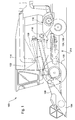
- an agricultural combine 100 that includes a self-propelled combine vehicle 102 and a harvesting head 104.
- Harvesting head 104 is supported on a feederhouse 106 with internal conveyor.
- Crop harvested by harvesting head 104 is carried up the internal conveyor to a threshing and separating system that includes a longitudinally extending rotor 108 that is disposed inside a concave 110.
- Grain that is separated in the threshing and separating process falls into a cleaning section 112. Clean grain from cleaning section 112 is carried upward by a conveyor (not shown) and is deposited in grain tank 114.
- the harvested material other than grain which includes such material as corn cobs, shucks, plant stalks and leaves, is conveyed backwards into an accelerator 116.
- Accelerator 116 conveys the unwanted material into a chopper 118.
- Chopper 118 chops and distributes the material over the field.
- Agricultural combine 100 is supported for travel over the field to harvest crops on two large front wheels 122 disposed on opposite sides of the front of the combine in mirror image positions. Agricultural combine 100 is also supported on two steerable rear wheels 124, 126. The wheels are supported on the chassis 103.
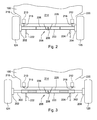
- agricultural combine 100 can be seen supported on a rear axle assembly 201, including rear axle 200 and steerable rear wheels 124, 126 mounted on the axle, as well as hubs, steering knuckles, vendors, lights, cables, linkages, hoses, and all the other hardware mounted for pivoting together with axle 200.
- rear axle assembly 201 including rear axle 200 and steerable rear wheels 124, 126 mounted on the axle, as well as hubs, steering knuckles, vendors, lights, cables, linkages, hoses, and all the other hardware mounted for pivoting together with axle 200.
- Steerable rear wheels 124, 126 are mounted on hubs that in turn are affixed to steering knuckles 202, 204, respectively. This arrangement permits the rear wheels 124, 126 to be steered about a generally vertical axis with respect to the ends of the axle 200.
- Axle 200 supports agricultural combine 100 at pivot coupling 206, which permits axle 200 to pivot with respect to the body of agricultural combine 100 about a pivotal axis 208 which extends longitudinally in the direction of travel of the combine and also horizontally.
- Axle oscillation stops 210, 212 are disposed adjacent to each end of the axle 200.
- Axle oscillation stops 210, 212 are fixed to the chassis 214 of agricultural combine 100.
- Axle oscillation stops 210, 212 have a lower end 215, 216 that is disposed to abut axle 200 when the axle pivots to prevent the axle from pivoting so far that wheels 124, 126 rub against the side walls 218, 220 of agricultural combine 100.
- a means for sensing the axle and wheel position (here shown as two axle position sensors 222, 224) is disposed to sense the degree of extension of axle 200 and the turning (or steering) angle of wheels 124, 126.
- Axle 200 is a telescopic axle and includes two internal hydraulic cylinders 226, 228 that are disposed to extend and retract an inner axle tube while the agricultural combine 100 is being driven through the field.
- FIGURE 3 illustrates the arrangement of FIGURE 2 but with axle 200 in an extended position.
- Axle 200 is extended by extending hydraulic cylinders 226, 228.
- axle 200 has been extended at each end to expose left side telescopic portion 300 located on the left hand side of agricultural combine 100 and right side telescopic portion 302 located on the right hand side of agricultural combine 100.
- wheels 124, 126 have been moved a significant distance away from side walls 218 and 220 of agricultural combine 100, respectively.
- axle assembly 201 can pivot through a larger angle about pivotal axis 208 without rubbing against, impacting, or otherwise damaging portions of the combine such as the side walls 218, 220.
- axle oscillation stops 210, 212 have been automatically adjusted to move their lower ends 215, 216 farther away (e.g. upward) from axle 200.
- axle 200 can rotate both clockwise and counterclockwise through a greater angle, thereby permitting the combine to travel over rougher terrain and still equalize the load on the wheels while preventing the wheels 124, 126 from damaging the body of agricultural combine 100.
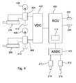
- FIGURE 4 illustrates the hydraulic cylinders 226, 228 that extend and retract axle 200, the sensors 222, 224 that sense the axle position and the wheel position, and the axle oscillation stops 210, 212, as well as the control circuitry and valves that operate the hydraulic cylinders, monitor the sensors, and adjust the axle oscillation stops automatically.
- An electronic control unit 400 is coupled to sensors 222, 224 and is configured to receive digital signals from the sensors indicating the amount of axle extension and the turning angle of wheels 124, 126.
- Electronic control unit 400 is also coupled to a valve driver circuit 402, which generates signals that control valves 404, 406.
- Valves 404, 406 are coupled to a source of hydraulic fluid under pressure 408 and a low-pressure hydraulic fluid reservoir 410. Valves 404, 406 are fluidly coupled to hydraulic cylinders 226, 228 to selectively and independently extend and retract hydraulic cylinders 226, 228 under the control of ECU 400.
- Electronic control unit 400 is configured to receive signals from sensors 222, 224 and to selectively extend and retract hydraulic cylinders 226, 228 responsively.
- Electronic control unit 400 is also configured to automatically adjust the position of axle oscillation stops 210, 212, as the electronic control unit 400 extends or retracts axle 200 to a position that ensures that axle 200 will not pivot so far that components of the rear axle assembly 201 will damage the body or chassis of agricultural combine 100.
- Electronic control unit 400 is further configured to automatically adjust the length of the axle oscillation stops 210, 212 as the vehicle is underway and as the length of axle 200 is changed to ensure that axle 200 cannot pivot to a position that will cause damage.
- the axle oscillation stop driver circuit 412 is configured to receive signals from electronic control unit 400 indicating the desired position of axle oscillation stops 210, 212, and to responsively generate signals that command the axle oscillation stops 210, 212 to extend or retract their lower ends 215, 216 to that desired position, thereby changing the maximum pivot angle of the rear axle assembly 201 in both the counterclockwise and the clockwise direction.
- Electronic control unit 400 is further configured to independently position in axle oscillation stops 210, 212 to accommodate differences between the left side pivot angle and the right side pivot angle.
- Electronic control unit 400 includes a nonvolatile memory 414 in which it stores the digital instructions executed by a digital microprocessor, which forms the core of the electronic control unit 400. These digital instructions command the electronic control unit 400 to automatically adjust the position of axle oscillation stops 210, 212 based at least upon the degree of axle extension as indicated by sensors 222, 224.
- Nonvolatile memory 414 also stores numeric values that indicate the relationship between the preferred position of axle oscillation stops 210, 212 for each of the extended positions of the left side telescopic portion 300 and right side telescopic portion 302 of axle 200. These values can be stored in a variety of formats well known to computer programmers.
- a lookup table can be stored in nonvolatile memory 414 that electronic control unit 400 accesses by (1) providing a value indicative of axle extension which it receives from sensors 222 or 224, and (2) by accessing the lookup table with that value, which responsively returns a value indicating the proper position of the corresponding axle oscillation stop 210, 212, respectively.
- a series of programmed mathematical calculations can be stored in nonvolatile memory 414 that are executed to calculate the value indicating the proper position of the corresponding axle oscillation stop 210, 212.
- electronic control unit 400 is configured to take the value indicating the proper position of the corresponding axle oscillation stop and transmit that value or another value indicative thereof to the axle oscillation stop driver circuit 412.
- Axle oscillation stop driver circuit 412 in turn, generates the appropriate signal or signals to drive axle oscillation stops 210, 212 to their appropriate positions.
- Electronic control unit 400 is configured to command valve driver circuits 404, 406 to extend or retract hydraulic cylinders 226, 228, and thus to extend or retract axle 200. Whenever electronic control unit 400 changes the length of axle 200, it is configured to substantially simultaneously determine the position of the axles, as described above, and automatically adjust the position of axle oscillation stops 210, 212.
Landscapes
- Engineering & Computer Science (AREA)
- Mechanical Engineering (AREA)
- Life Sciences & Earth Sciences (AREA)
- Environmental Sciences (AREA)
- Guiding Agricultural Machines (AREA)
- Vehicle Body Suspensions (AREA)
- Harvester Elements (AREA)
Abstract
Description
- The invention relates generally to agricultural combines. It relates in particular to oscillation stops for the rear axles of agricultural combines. More particularly it relates to automatically adjustable axle oscillation stops for rear axles of agricultural combines.
- Agricultural combines are typically equipped with large front drive wheels that support the bulk of the weight of the agricultural combine as it travels through the field harvesting crops. They're also typically equipped with rear steerable wheels that are smaller in diameter than the front wheels and are configured to carry a smaller load.
- One of the problems faced by agricultural combines is the need to maintain good contact with the ground as the terrain changes underneath the wheels, and also to minimize ground compaction as much as possible. If good contact is not maintained, wheels can spin and the agricultural combine can stall in the field. In addition, if the load shifts from wheel to wield added force on a wheel can call as the ground under that wheel to become unnecessarily compacted.
- A traditional way to alleviate these problems has been to mount the rear steerable wheels on a pivoting axle. The axle is typically arranged to pivot about a pivotal axis of the agricultural combine that extends longitudinally and horizontally, parallel with the direction of forward travel as the agricultural combine is driven through the field. If the terrain over which the two large front drive wheels passes causes the agricultural combine to roll to the left, for example, the combine body will pivot about the longitudinal pivot axis of the rear axle. In this manner, the load is evenly distributed over the 4 wheels as much as possible and all four wheels maintain good contact with the ground.
- The ability of the rear axle to pivot is not unlimited, however. Typically there are mechanical stops mounted to the axle, or to the frame above the axle at each end of the axle adjacent to the rear wheels of the agricultural combine. Without the stops, the combine could travel over rough terrain sufficient to cause the axle to pivot until one of the rear wheels rubs against the side of the combine and its mechanical components. This can cause the mechanical components to fail.
- No one axle oscillation stop is suited for every situation, because wheels having tires of a variety of widths and heights can be used on a combine. If the dimensions of the wheel and tire change, the position of the axle oscillation stop should change as well. By adjusting the stop when the wheels and tires are changed, the maximum range of movement of the axle can be provided while still preventing the wheel and tire from damaging the side of the combine.
- Furthermore, axles of agricultural combines are typically made so they can be extended or retracted. If an axle is extended (for example to permit a larger wheel and tire to be used) it is desirable to adjust the axle oscillation stops as well.
- Unfortunately, there is no easy way to determine the best axle oscillation stop position when changing wheels, tires, and adjusting the length of the axle. As a further complication, future combines are now being proposed that we'll have not only a pivotable rear axle, but an automatically extendable and retractable rear axle. In these future combines, the rear axle of a combine can be extended and retracted, as necessary, to provide even where, or to provide steering clearance between the rear wheels and the sides of the combine automatically as the wheels are steered.
- The purpose underlying this invention is seen in the need to provide an automatically adjustable axle oscillation stop that can automatically change the stop position in response to a determination of axle extension.
- The problem is solved according to the invention at least by the teaching of patent claim 1, where the further patent claims cite characteristics that further develop the solution to great advantage.
- In accordance with one aspect of the Invention, and automatically adjustable oscillation stop for a steerable rear axle of an agricultural combine is provided, the combine having a longitudinal axis extending in a direction of travel, a chassis, two front drive wheels supported on the chassis, two rear steerable wheels disposed on a rear axle assembly that is supported on the chassis at a pivot coupling thereby permitting the rear axle assembly to pivot about a pivotal axis through a pivot angle, the rear axle assembly being extendible to permit at least a first of the two rear steerable wheels to have a first plurality of lateral positions, in which the automatically adjustable oscillation stop includes a first stop, interposed between the chassis of the agricultural combine and the rear axle assembly and configured to limit the pivot angle in a first direction of rotation about the pivotal axis, the first stop having a first plurality of different first stop positions, each of said first stop positions corresponding to a different pivot angle limit; a first sensor configured to generate a first signal indicative of the first plurality of lateral positions; and an electronic control unit coupled to the first stop to command the first stop to said first plurality of different first stop positions and coupled to the first sensor to receive the first signal therefrom, said electronic control unit having a non-volatile memory storing a first plurality of digital computer instructions, said first plurality further including instructions directing the electronic control unit to read the first signal, to digitally calculate a stop position for said first stop based at least upon the first signal that will prevent at least one component of the rear axle assembly from dragging against the agricultural combine when said rear axle assembly pivots with respect to the chassis of the agricultural combine.
- The rear axle assembly may be extendible to permit at least a second of the two rear steerable wheels to have a second plurality of lateral positions. The oscillation stop may also include a second stop, the second stop being interposed between the chassis and the rear axle assembly, said second stop configured to limit the pivot angle in a second direction of rotation about the pivotal axis, said second stop having a first plurality of different second stop positions, each of said second stop positions corresponding to a different pivot angle limit; a second sensor configured to generate a second signal indicative of the second plurality of lateral positions; and the electronic control unit may be coupled to the second stop to command the second stop to said first plurality of second stop positions and may be coupled to the second sensor to receive the second signal therefrom. The electronic control unit may have a non-volatile memory configured to store a second plurality of digital computer instructions. The second plurality may include instructions directing the electronic control unit to read the second signal, to digitally calculate a stop position for said second stop based at least upon the second signal that will prevent at least another component of the rear axle assembly from dragging against the agricultural combine when said rear axle assembly pivots with respect to the chassis of the agricultural combine. The first stop may be fixed to the chassis of the agricultural combine and may abut the rear axle assembly at each of said first stop positions to stop further rear axle rotation in the first direction of rotation. The first stop may be fixed to the chassis of the agricultural combine and many the rear axle assembly on one side of the pivot coupling in each of said first stop positions to stop rear axle rotation in the first direction of rotation. The second stop may be fixed to the chassis of the agricultural combine and may abut the rear axle assembly on another side of the pivot coupling in each of the second stop positions to stop rear axle rotation in the second direction of rotation. The electronic control unit may be configured to automatically adjust the position of the first stop while the agricultural combine is moving over the ground. The electronic control unit maybe configured to automatically adjust the position of the first stop and the second stop when the agricultural combine is moving over the ground. The automatically adjustable oscillation stop may further include a second stop that is configured to limit the pivot angle in a second direction of rotation about the pivotal axis. The electronic control unit maybe coupled to the second stop to command the second stop to move to a plurality of second stop positions.
- In accordance with a second aspect of the invention, an automatically adjustable oscillation stop of an agricultural combine includes a sensor to sense the position of an extendible axle, an electronic control unit to read the sensor and calculate a stop position based at least on the sensor signal, and an adjustable stop disposed to limit the range of pivoting of the extendible axle, the adjustable stop being controlled by the electronic control unit to move to the stop position.
-
-
FIGURE 1 illustrates a left side view of an agricultural combine in accordance with the present invention. -
FIGURE 2 is a schematic rear view of the combine ofFIGURE 1 . -
FIGURE 3 is a schematic rear view of the combine ofFIGURE 2 , but showing the rear axle of the agricultural combine as compared to the position shown inFIGURE 2 . -
FIGURE 4 is a schematic diagram of the axle oscillation stops and associated control circuitry. - In
FIGURE 1 , anagricultural combine 100 is shown that includes a self-propelledcombine vehicle 102 and a harvestinghead 104. Harvestinghead 104 is supported on afeederhouse 106 with internal conveyor. Crop harvested by harvestinghead 104 is carried up the internal conveyor to a threshing and separating system that includes a longitudinally extendingrotor 108 that is disposed inside a concave 110. Grain that is separated in the threshing and separating process falls into acleaning section 112. Clean grain fromcleaning section 112 is carried upward by a conveyor (not shown) and is deposited ingrain tank 114. The harvested material other than grain (MOG), which includes such material as corn cobs, shucks, plant stalks and leaves, is conveyed backwards into anaccelerator 116.Accelerator 116 conveys the unwanted material into achopper 118. Chopper 118 chops and distributes the material over the field. -
Agricultural combine 100 is supported for travel over the field to harvest crops on two largefront wheels 122 disposed on opposite sides of the front of the combine in mirror image positions.Agricultural combine 100 is also supported on two steerablerear wheels - Referring now to
FIGURE 2 ,agricultural combine 100 can be seen supported on a rear axle assembly 201, includingrear axle 200 and steerablerear wheels axle 200. These additional items of rear axle assembly 201 have not been shown herein in order to more clearly show the construction and operation of the extendable axle. - Steerable
rear wheels steering knuckles rear wheels axle 200. - Axle 200 supports
agricultural combine 100 atpivot coupling 206, which permitsaxle 200 to pivot with respect to the body ofagricultural combine 100 about apivotal axis 208 which extends longitudinally in the direction of travel of the combine and also horizontally. Axle oscillation stops 210, 212 are disposed adjacent to each end of theaxle 200. Axle oscillation stops 210, 212 are fixed to thechassis 214 ofagricultural combine 100. Axle oscillation stops 210, 212 have alower end abut axle 200 when the axle pivots to prevent the axle from pivoting so far thatwheels side walls agricultural combine 100. - A means for sensing the axle and wheel position (here shown as two
axle position sensors 222, 224) is disposed to sense the degree of extension ofaxle 200 and the turning (or steering) angle ofwheels -
Axle 200 is a telescopic axle and includes two internalhydraulic cylinders agricultural combine 100 is being driven through the field. - Other arrangements for extending and retracting an axle and steering the wheels mounted thereon can be found in co-pending United States Patent Application No.
12/463,628 -
FIGURE 3 illustrates the arrangement ofFIGURE 2 but withaxle 200 in an extended position.Axle 200 is extended by extendinghydraulic cylinders FIGURE 3 ,axle 200 has been extended at each end to expose left sidetelescopic portion 300 located on the left hand side ofagricultural combine 100 and right sidetelescopic portion 302 located on the right hand side ofagricultural combine 100. By extendingaxle 200,wheels side walls agricultural combine 100, respectively. As a result, axle assembly 201 can pivot through a larger angle aboutpivotal axis 208 without rubbing against, impacting, or otherwise damaging portions of the combine such as theside walls - To permit
axle 200 to pivot to this greater angle, axle oscillation stops 210, 212 have been automatically adjusted to move their lower ends 215, 216 farther away (e.g. upward) fromaxle 200. By moving the lower ends of the axle oscillation stops farther away,axle 200 can rotate both clockwise and counterclockwise through a greater angle, thereby permitting the combine to travel over rougher terrain and still equalize the load on the wheels while preventing thewheels agricultural combine 100. -
FIGURE 4 illustrates thehydraulic cylinders axle 200, thesensors - An
electronic control unit 400 is coupled tosensors wheels Electronic control unit 400 is also coupled to avalve driver circuit 402, which generates signals that controlvalves Valves pressure 408 and a low-pressurehydraulic fluid reservoir 410.Valves hydraulic cylinders hydraulic cylinders ECU 400. -
Electronic control unit 400 is configured to receive signals fromsensors hydraulic cylinders -
Electronic control unit 400 is also configured to automatically adjust the position of axle oscillation stops 210, 212, as theelectronic control unit 400 extends or retractsaxle 200 to a position that ensures thataxle 200 will not pivot so far that components of the rear axle assembly 201 will damage the body or chassis ofagricultural combine 100. - It should be recognized that at each possible telescopic position of
axle 200, there is a corresponding maximum upward pivot angle for theleft wheel 124 and a corresponding maximum upward pivot angle for theright wheel 126. These two angles are not necessarily the same on the right side as on the left side since there may be different mechanical components extending from the sides of the vehicle. Therefore, although the combine is shown with symmetric sidewalls and symmetric clearance inFIGURES 2 and 3 , this symmetry is not necessary to the invention. - For each permissible maximum angle of pivot of
axle 200, there is a corresponding axle oscillation stop position for axle oscillation stops 210, 212.Electronic control unit 400 is further configured to automatically adjust the length of the axle oscillation stops 210, 212 as the vehicle is underway and as the length ofaxle 200 is changed to ensure thataxle 200 cannot pivot to a position that will cause damage. - To automatically control the positions of axle oscillation stops 210, 212,
electronic control unit 400 is coupled to an axle oscillationstop driver circuit 412. - The axle oscillation
stop driver circuit 412 is configured to receive signals fromelectronic control unit 400 indicating the desired position of axle oscillation stops 210, 212, and to responsively generate signals that command the axle oscillation stops 210, 212 to extend or retract their lower ends 215, 216 to that desired position, thereby changing the maximum pivot angle of the rear axle assembly 201 in both the counterclockwise and the clockwise direction.Electronic control unit 400 is further configured to independently position in axle oscillation stops 210, 212 to accommodate differences between the left side pivot angle and the right side pivot angle. -
Electronic control unit 400 includes anonvolatile memory 414 in which it stores the digital instructions executed by a digital microprocessor, which forms the core of theelectronic control unit 400. These digital instructions command theelectronic control unit 400 to automatically adjust the position of axle oscillation stops 210, 212 based at least upon the degree of axle extension as indicated bysensors -
Nonvolatile memory 414 also stores numeric values that indicate the relationship between the preferred position of axle oscillation stops 210, 212 for each of the extended positions of the left sidetelescopic portion 300 and right sidetelescopic portion 302 ofaxle 200. These values can be stored in a variety of formats well known to computer programmers. - For example, a lookup table can be stored in
nonvolatile memory 414 thatelectronic control unit 400 accesses by (1) providing a value indicative of axle extension which it receives fromsensors axle oscillation stop - In another common arrangement, a series of programmed mathematical calculations can be stored in
nonvolatile memory 414 that are executed to calculate the value indicating the proper position of the correspondingaxle oscillation stop - By whatever method the lookups or calculations are performed,
electronic control unit 400 is configured to take the value indicating the proper position of the corresponding axle oscillation stop and transmit that value or another value indicative thereof to the axle oscillationstop driver circuit 412. Axle oscillationstop driver circuit 412, in turn, generates the appropriate signal or signals to drive axle oscillation stops 210, 212 to their appropriate positions. -
Electronic control unit 400 is configured to commandvalve driver circuits hydraulic cylinders axle 200. Wheneverelectronic control unit 400 changes the length ofaxle 200, it is configured to substantially simultaneously determine the position of the axles, as described above, and automatically adjust the position of axle oscillation stops 210, 212.
Claims (9)
- An automatically adjustable oscillation stop for a steerable rear axle of an agricultural combine (100), the combine (100) having a longitudinal axis extending in a direction of travel, a chassis (214), two front drive wheels (120, 122) supported on the chassis (214), two rear steerable wheels (124, 126) disposed on a rear axle assembly (201) that is supported on the chassis (214) at a pivot coupling (206) thereby permitting the rear axle assembly (201) to pivot about a pivotal axis (208) through a pivot angle, the rear axle assembly (201) being extendible to permit at least a first of the two rear steerable wheels (124, 126) to have a first plurality of lateral positions, the oscillation stop comprising:a first stop (210, 212), said first stop (210, 212) being interposed between the chassis (214) of the agricultural combine (100) and the rear axle assembly (201), said first stop (210, 212) configured to limit the pivot angle in a first direction of rotation about the pivotal axis (208), said first stop (210, 212) having a first plurality of different first stop positions, each of said first stop positions corresponding to a different pivot angle limit;a first sensor (222, 224) configured to generate a first signal indicative of the first plurality of lateral positions; andan electronic control unit (400) coupled to the first stop (210, 212) to command said first stop (210, 212) to said first plurality of different first stop positions and coupled to the first sensor to receive the first signal therefrom, said electronic control unit (400) having a non-volatile memory (414) storing a first plurality of digital computer instructions, said first plurality further including instructions directing the electronic control unit (400) to read the first signal, to digitally calculate a stop position for said first stop (210, 212) based at least upon the first signal that will prevent at least one component of the rear axle assembly (201) from dragging against the agricultural combine when said rear axle assembly (201) pivots with respect to the chassis (214) of the agricultural combine (100).
- The automatically adjustable oscillation stop of Claim 1, wherein the rear axle assembly (201) is extendible to permit at least a second of the two rear steerable wheels (124, 126) to have a second plurality of lateral positions, the oscillation stop comprising:a second stop (210, 212), said second stop (210, 212) being interposed between the chassis (214) and the rear axle assembly (201), said second stop (210, 212) configured to limit the pivot angle in a second direction of rotation about the pivotal axis (208), said second stop (210, 212) having a first plurality of different second stop positions, each of said second stop positions corresponding to a different pivot angle limit;a second sensor (222, 224) configured to generate a second signal indicative of the second plurality of lateral positions; andwherein the electronic control unit (400) is coupled to the second stop (210, 212) to command said second stop (210, 212) to said first plurality of second stop positions and coupled to the second sensor (222, 224) to receive the second signal therefrom, said electronic control unit having a non-volatile memory (414) storing a second plurality of digital computer instructions, including instructions directing the electronic control unit (400) to read the second signal, to digitally calculate a stop position for said second stop (210, 212) based at least upon the second signal that will prevent at least another component of the rear axle assembly (201) from dragging against the agricultural combine when said rear axle assembly (201) pivots with respect to the chassis (214) of the agricultural combine (100).
- The automatically adjustable oscillation stop of Claim 1, wherein the first stop (210, 212) is fixed to the chassis (214) of the agricultural combine (100) and abuts the rear axle assembly (201) at each of said first stop positions to stop further rear axle rotation in the first direction of rotation.
- The automatically adjustable oscillation stop of Claim 2, wherein the first stop (210, 212) is fixed to the chassis (214) of the agricultural combine (100) and abuts the rear axle assembly (201) on one side of the pivot coupling (206) in each of said first stop positions to stop rear axle rotation in the first direction of rotation, and further wherein the second stop (210, 212) is fixed to the chassis (214) of the agricultural combine (100) and abuts the rear axle assembly (201) on another side of the pivot coupling (206) in each of said second stop positions to stop rear axle rotation in the second direction of rotation.
- The automatically adjustable oscillation stop of Claim 1, wherein the electronic control unit (400) is configured to automatically adjust the position of the first stop (210, 212) while the agricultural combine (100) is moving over the ground.
- The automatically adjustable oscillation stop of Claim 2, wherein the electronic control unit (400) is configured to automatically adjust the position of the first stop (210, 212) and the second stop (210, 212) when the agricultural combine (100) is moving over the ground.
- The automatically adjustable oscillation stop of Claim 1, further comprising a second stop (210, 212) that is configured to limit the pivot angle in a second direction of rotation about the pivotal axis (208), wherein the electronic control unit (400) is coupled to the second stop (210, 212) to command said second stop (210, 212) to move to a plurality of second stop positions.
- An automatically adjustable oscillation stop of an agricultural combine (100) includes a sensor (222, 224) to sense the position of an extendible axle (200), an electronic control unit (400) to read the sensor (222, 224) and calculate a stop position based at least on the sensor signal, and an adjustable stop (210, 212) disposed to limit the range of pivoting of the extendible axle (200), the adjustable stop (210, 212) being controlled by the electronic control unit (400) to move to the stop position.
- An agricultural combine (100) having a longitudinal axis extending in a direction of travel, a chassis (214), two front drive wheels (120, 122) supported on the chassis (214), two rear steerable wheels (124, 126) disposed on a rear axle assembly (201) that is supported on the chassis (214) at a pivot coupling (206) thereby permitting the rear axle assembly (201) to pivot about a pivotal axis (208) through a pivot angle, the rear axle assembly (201) being extendible to permit at least a first of the two rear steerable wheels (124, 126) to have a first plurality of lateral positions, and an automatically adjustable oscillation stop according to one of the preceding claims.
Applications Claiming Priority (1)
| Application Number | Priority Date | Filing Date | Title |
|---|---|---|---|
| US12/785,703 US8280590B2 (en) | 2010-05-24 | 2010-05-24 | Automatically adjustable axle oscillation stops |
Publications (2)
| Publication Number | Publication Date |
|---|---|
| EP2389798A1 true EP2389798A1 (en) | 2011-11-30 |
| EP2389798B1 EP2389798B1 (en) | 2014-01-15 |
Family
ID=44351416
Family Applications (1)
| Application Number | Title | Priority Date | Filing Date |
|---|---|---|---|
| EP11164519.8A Not-in-force EP2389798B1 (en) | 2010-05-24 | 2011-05-03 | Automatically adjustable axle oscillation stops |
Country Status (4)
| Country | Link |
|---|---|
| US (1) | US8280590B2 (en) |
| EP (1) | EP2389798B1 (en) |
| CN (1) | CN102257906A (en) |
| BR (1) | BRPI1102262B1 (en) |
Cited By (4)
| Publication number | Priority date | Publication date | Assignee | Title |
|---|---|---|---|---|
| WO2019197013A1 (en) * | 2018-04-09 | 2019-10-17 | Vitirover | Robot and method for controlling the robot |
| WO2019197012A1 (en) * | 2018-04-09 | 2019-10-17 | Vitirover | Stop element for a robot having a chassis and a free rear axle housing with two axes of rotation with respect to the chassis |
| EP3798028A1 (en) * | 2019-09-30 | 2021-03-31 | CLAAS Tractor S.A.S. | Agricultural machine and method for steering an agricultural machine |
| WO2023200589A1 (en) * | 2022-04-11 | 2023-10-19 | Oshkosh Corporation | Systems and methods for leveling and oscillation control of a lift device |
Families Citing this family (11)
| Publication number | Priority date | Publication date | Assignee | Title |
|---|---|---|---|---|
| US9561819B2 (en) * | 2013-12-19 | 2017-02-07 | Cnh Industrial America Llc | System and method for actively determining a steering stop angle for a work vehicle |
| CN106457944B (en) * | 2014-04-09 | 2019-05-03 | 凯斯纽荷兰(中国)管理有限公司 | Roll stop arrangement for suspension systems in off-highway vehicles |
| DE102014216112A1 (en) * | 2014-08-13 | 2016-02-18 | Walter Schmid | Self-propelled harvester |
| US9968023B2 (en) | 2016-06-07 | 2018-05-15 | Cnh Industrial America Llc | Systems and methods for adjusting wheel spacing of an agricultural implement |
| US10518580B2 (en) | 2017-07-24 | 2019-12-31 | Cnh Industrial America Llc | Telescoping axle for an agricultural applicator |
| US10828952B2 (en) * | 2018-12-04 | 2020-11-10 | Cnh Industrial America Llc | Suspension system for a work vehicle |
| US11597638B2 (en) * | 2019-04-05 | 2023-03-07 | Oshkosh Corporation | Oscillating axle for lift device |
| US12016257B2 (en) | 2020-02-19 | 2024-06-25 | Sabanto, Inc. | Methods for detecting and clearing debris from planter gauge wheels, closing wheels and seed tubes |
| US12461083B2 (en) | 2020-08-03 | 2025-11-04 | Sabanto, Inc. | Methods for improved agricultural procedures |
| GB202014403D0 (en) * | 2020-09-14 | 2020-10-28 | Agco Do Brasil Solucoes Argicolas Ltda | Vehicle having a tilting axle and related matters |
| US11607910B1 (en) * | 2022-03-01 | 2023-03-21 | Caterpillar Inc. | Axle oscillation stop for construction machine |
Citations (6)
| Publication number | Priority date | Publication date | Assignee | Title |
|---|---|---|---|---|
| DE2031910A1 (en) * | 1970-06-27 | 1972-01-05 | Klöckner-Humboldt-Deutz AG, 5000 Köln-Deutz | Steerable pedel axle |
| JPS62275812A (en) * | 1986-05-22 | 1987-11-30 | Yutani Heavy Ind Ltd | Wheel shaft suspension for wheel type construction vehicle |
| JPS63195002A (en) * | 1987-02-06 | 1988-08-12 | Kubota Ltd | Vehicle wheel length adjustment device |
| DE10247699A1 (en) * | 2002-10-12 | 2004-04-22 | Deere & Company, Moline | Steering device for harvesting machine for agricultural crops has wheel holder able to turn relative to turning holder |
| EP1502769A2 (en) * | 2003-07-31 | 2005-02-02 | Deere & Company | Agricultural Vehicle |
| EP2168786A2 (en) * | 2008-09-24 | 2010-03-31 | Deere & Company | Steering axle transport positioning structure and method |
Family Cites Families (6)
| Publication number | Priority date | Publication date | Assignee | Title |
|---|---|---|---|---|
| CN2091804U (en) * | 1991-04-09 | 1992-01-01 | 祁文浩 | Deformable tractor |
| US5447321A (en) * | 1994-07-08 | 1995-09-05 | New Holland North America, Inc. | Oscillation stop mechanism for compact tractors |
| TW445224B (en) * | 1997-03-25 | 2001-07-11 | Toyoda Automatic Loom Works | Axle controller for industrial vehicles |
| JPH10338496A (en) * | 1997-06-11 | 1998-12-22 | Toyota Autom Loom Works Ltd | Oscillation controller and front and rear center of gravity position assuming device of industrial vehicle |
| JPH11115436A (en) * | 1997-10-15 | 1999-04-27 | Toyota Autom Loom Works Ltd | Support structure of fluid pressure cylinder for controlling axle oscillation |
| DK174320B1 (en) * | 2001-02-22 | 2002-12-02 | Niels Kjaer Laursen | Chassis with height adjustable wheels for adjusting the chassis part orientation to a reference orientation |
-
2010
- 2010-05-24 US US12/785,703 patent/US8280590B2/en active Active
-
2011
- 2011-05-03 EP EP11164519.8A patent/EP2389798B1/en not_active Not-in-force
- 2011-05-05 CN CN2011101151113A patent/CN102257906A/en active Pending
- 2011-05-20 BR BRPI1102262-0A patent/BRPI1102262B1/en active IP Right Grant
Patent Citations (6)
| Publication number | Priority date | Publication date | Assignee | Title |
|---|---|---|---|---|
| DE2031910A1 (en) * | 1970-06-27 | 1972-01-05 | Klöckner-Humboldt-Deutz AG, 5000 Köln-Deutz | Steerable pedel axle |
| JPS62275812A (en) * | 1986-05-22 | 1987-11-30 | Yutani Heavy Ind Ltd | Wheel shaft suspension for wheel type construction vehicle |
| JPS63195002A (en) * | 1987-02-06 | 1988-08-12 | Kubota Ltd | Vehicle wheel length adjustment device |
| DE10247699A1 (en) * | 2002-10-12 | 2004-04-22 | Deere & Company, Moline | Steering device for harvesting machine for agricultural crops has wheel holder able to turn relative to turning holder |
| EP1502769A2 (en) * | 2003-07-31 | 2005-02-02 | Deere & Company | Agricultural Vehicle |
| EP2168786A2 (en) * | 2008-09-24 | 2010-03-31 | Deere & Company | Steering axle transport positioning structure and method |
Cited By (6)
| Publication number | Priority date | Publication date | Assignee | Title |
|---|---|---|---|---|
| WO2019197013A1 (en) * | 2018-04-09 | 2019-10-17 | Vitirover | Robot and method for controlling the robot |
| WO2019197012A1 (en) * | 2018-04-09 | 2019-10-17 | Vitirover | Stop element for a robot having a chassis and a free rear axle housing with two axes of rotation with respect to the chassis |
| EP3798028A1 (en) * | 2019-09-30 | 2021-03-31 | CLAAS Tractor S.A.S. | Agricultural machine and method for steering an agricultural machine |
| WO2023200589A1 (en) * | 2022-04-11 | 2023-10-19 | Oshkosh Corporation | Systems and methods for leveling and oscillation control of a lift device |
| US12071332B2 (en) | 2022-04-11 | 2024-08-27 | Oshkosh Corporation | Systems and methods for leveling and oscillation control of a lift device |
| US12577085B2 (en) | 2022-04-11 | 2026-03-17 | Oshkosh Corporation | Systems and methods for leveling and oscillation control of a lift device |
Also Published As
| Publication number | Publication date |
|---|---|
| US20110288726A1 (en) | 2011-11-24 |
| US8280590B2 (en) | 2012-10-02 |
| CN102257906A (en) | 2011-11-30 |
| BRPI1102262A2 (en) | 2012-11-06 |
| EP2389798B1 (en) | 2014-01-15 |
| BRPI1102262B1 (en) | 2018-01-16 |
Similar Documents
| Publication | Publication Date | Title |
|---|---|---|
| EP2389798B1 (en) | Automatically adjustable axle oscillation stops | |
| EP3469878B1 (en) | Roll center for harvester attachment frame control arms | |
| EP3446558B2 (en) | Agricultural header with one or more movable wing sections | |
| US7555884B2 (en) | Self-propelled harvesting machine with a front harvesting attachment that can be pivoted about a vertical axis | |
| US7661251B1 (en) | Header float system for use with an agricultural windrower or combine | |
| US7954583B2 (en) | Agricultural harvester rear axle arrangement for narrow transport | |
| US9320197B2 (en) | Self-propelled agricultural harvesting machine having a crop attachment which is pivotable about a vertical axis | |
| US10674652B2 (en) | Harvester with adjustable row dividers | |
| US20230337563A1 (en) | Mounting Assembly for a Steerable Wheel with Variable Track Width | |
| US8820758B2 (en) | Additional axle for agricultural machine weight redistribution | |
| AU2008200792A1 (en) | Floating header with integrated float system for use with an agricultural windrower or combine | |
| US6267198B1 (en) | Offset kingpin for a rear steering axle on an agricultural combine | |
| EP2997811B1 (en) | Multi-purpose spreader of an agricultural vehicle | |
| US20060019732A1 (en) | Discharge arrangement of an agricultural harvesting machine | |
| US12408590B2 (en) | Rigid cutterbar over travel | |
| US12251961B2 (en) | Vehicle having a tilting axle and related methods | |
| EP3714677B1 (en) | Header transport system | |
| US8821228B1 (en) | Dual bin combine system |
Legal Events
| Date | Code | Title | Description |
|---|---|---|---|
| AK | Designated contracting states |
Kind code of ref document: A1 Designated state(s): AL AT BE BG CH CY CZ DE DK EE ES FI FR GB GR HR HU IE IS IT LI LT LU LV MC MK MT NL NO PL PT RO RS SE SI SK SM TR |
|
| AX | Request for extension of the european patent |
Extension state: BA ME |
|
| PUAI | Public reference made under article 153(3) epc to a published international application that has entered the european phase |
Free format text: ORIGINAL CODE: 0009012 |
|
| 17P | Request for examination filed |
Effective date: 20120530 |
|
| GRAP | Despatch of communication of intention to grant a patent |
Free format text: ORIGINAL CODE: EPIDOSNIGR1 |
|
| RIC1 | Information provided on ipc code assigned before grant |
Ipc: B60G 9/02 20060101ALI20130830BHEP Ipc: A01D 41/12 20060101AFI20130830BHEP Ipc: B62D 49/06 20060101ALN20130830BHEP |
|
| INTG | Intention to grant announced |
Effective date: 20130925 |
|
| GRAS | Grant fee paid |
Free format text: ORIGINAL CODE: EPIDOSNIGR3 |
|
| GRAA | (expected) grant |
Free format text: ORIGINAL CODE: 0009210 |
|
| AK | Designated contracting states |
Kind code of ref document: B1 Designated state(s): AL AT BE BG CH CY CZ DE DK EE ES FI FR GB GR HR HU IE IS IT LI LT LU LV MC MK MT NL NO PL PT RO RS SE SI SK SM TR |
|
| REG | Reference to a national code |
Ref country code: GB Ref legal event code: FG4D Ref country code: CH Ref legal event code: EP |
|
| REG | Reference to a national code |
Ref country code: AT Ref legal event code: REF Ref document number: 649368 Country of ref document: AT Kind code of ref document: T Effective date: 20140215 |
|
| REG | Reference to a national code |
Ref country code: IE Ref legal event code: FG4D |
|
| REG | Reference to a national code |
Ref country code: DE Ref legal event code: R096 Ref document number: 602011004669 Country of ref document: DE Effective date: 20140227 |
|
| REG | Reference to a national code |
Ref country code: NL Ref legal event code: VDEP Effective date: 20140115 |
|
| REG | Reference to a national code |
Ref country code: AT Ref legal event code: MK05 Ref document number: 649368 Country of ref document: AT Kind code of ref document: T Effective date: 20140115 |
|
| REG | Reference to a national code |
Ref country code: LT Ref legal event code: MG4D |
|
| PG25 | Lapsed in a contracting state [announced via postgrant information from national office to epo] |
Ref country code: IS Free format text: LAPSE BECAUSE OF FAILURE TO SUBMIT A TRANSLATION OF THE DESCRIPTION OR TO PAY THE FEE WITHIN THE PRESCRIBED TIME-LIMIT Effective date: 20140515 Ref country code: NO Free format text: LAPSE BECAUSE OF FAILURE TO SUBMIT A TRANSLATION OF THE DESCRIPTION OR TO PAY THE FEE WITHIN THE PRESCRIBED TIME-LIMIT Effective date: 20140415 Ref country code: LT Free format text: LAPSE BECAUSE OF FAILURE TO SUBMIT A TRANSLATION OF THE DESCRIPTION OR TO PAY THE FEE WITHIN THE PRESCRIBED TIME-LIMIT Effective date: 20140115 |
|
| PG25 | Lapsed in a contracting state [announced via postgrant information from national office to epo] |
Ref country code: FI Free format text: LAPSE BECAUSE OF FAILURE TO SUBMIT A TRANSLATION OF THE DESCRIPTION OR TO PAY THE FEE WITHIN THE PRESCRIBED TIME-LIMIT Effective date: 20140115 Ref country code: PT Free format text: LAPSE BECAUSE OF FAILURE TO SUBMIT A TRANSLATION OF THE DESCRIPTION OR TO PAY THE FEE WITHIN THE PRESCRIBED TIME-LIMIT Effective date: 20140515 Ref country code: CY Free format text: LAPSE BECAUSE OF FAILURE TO SUBMIT A TRANSLATION OF THE DESCRIPTION OR TO PAY THE FEE WITHIN THE PRESCRIBED TIME-LIMIT Effective date: 20140115 Ref country code: ES Free format text: LAPSE BECAUSE OF FAILURE TO SUBMIT A TRANSLATION OF THE DESCRIPTION OR TO PAY THE FEE WITHIN THE PRESCRIBED TIME-LIMIT Effective date: 20140115 Ref country code: AT Free format text: LAPSE BECAUSE OF FAILURE TO SUBMIT A TRANSLATION OF THE DESCRIPTION OR TO PAY THE FEE WITHIN THE PRESCRIBED TIME-LIMIT Effective date: 20140115 Ref country code: SE Free format text: LAPSE BECAUSE OF FAILURE TO SUBMIT A TRANSLATION OF THE DESCRIPTION OR TO PAY THE FEE WITHIN THE PRESCRIBED TIME-LIMIT Effective date: 20140115 Ref country code: NL Free format text: LAPSE BECAUSE OF FAILURE TO SUBMIT A TRANSLATION OF THE DESCRIPTION OR TO PAY THE FEE WITHIN THE PRESCRIBED TIME-LIMIT Effective date: 20140115 |
|
| PGFP | Annual fee paid to national office [announced via postgrant information from national office to epo] |
Ref country code: IT Payment date: 20140531 Year of fee payment: 4 Ref country code: DE Payment date: 20140423 Year of fee payment: 4 |
|
| PG25 | Lapsed in a contracting state [announced via postgrant information from national office to epo] |
Ref country code: RS Free format text: LAPSE BECAUSE OF FAILURE TO SUBMIT A TRANSLATION OF THE DESCRIPTION OR TO PAY THE FEE WITHIN THE PRESCRIBED TIME-LIMIT Effective date: 20140115 Ref country code: HR Free format text: LAPSE BECAUSE OF FAILURE TO SUBMIT A TRANSLATION OF THE DESCRIPTION OR TO PAY THE FEE WITHIN THE PRESCRIBED TIME-LIMIT Effective date: 20140115 Ref country code: LV Free format text: LAPSE BECAUSE OF FAILURE TO SUBMIT A TRANSLATION OF THE DESCRIPTION OR TO PAY THE FEE WITHIN THE PRESCRIBED TIME-LIMIT Effective date: 20140115 |
|
| PGFP | Annual fee paid to national office [announced via postgrant information from national office to epo] |
Ref country code: BE Payment date: 20140530 Year of fee payment: 4 |
|
| REG | Reference to a national code |
Ref country code: DE Ref legal event code: R097 Ref document number: 602011004669 Country of ref document: DE |
|
| PG25 | Lapsed in a contracting state [announced via postgrant information from national office to epo] |
Ref country code: EE Free format text: LAPSE BECAUSE OF FAILURE TO SUBMIT A TRANSLATION OF THE DESCRIPTION OR TO PAY THE FEE WITHIN THE PRESCRIBED TIME-LIMIT Effective date: 20140115 Ref country code: DK Free format text: LAPSE BECAUSE OF FAILURE TO SUBMIT A TRANSLATION OF THE DESCRIPTION OR TO PAY THE FEE WITHIN THE PRESCRIBED TIME-LIMIT Effective date: 20140115 Ref country code: RO Free format text: LAPSE BECAUSE OF FAILURE TO SUBMIT A TRANSLATION OF THE DESCRIPTION OR TO PAY THE FEE WITHIN THE PRESCRIBED TIME-LIMIT Effective date: 20140115 Ref country code: CZ Free format text: LAPSE BECAUSE OF FAILURE TO SUBMIT A TRANSLATION OF THE DESCRIPTION OR TO PAY THE FEE WITHIN THE PRESCRIBED TIME-LIMIT Effective date: 20140115 |
|
| PLBE | No opposition filed within time limit |
Free format text: ORIGINAL CODE: 0009261 |
|
| STAA | Information on the status of an ep patent application or granted ep patent |
Free format text: STATUS: NO OPPOSITION FILED WITHIN TIME LIMIT |
|
| PG25 | Lapsed in a contracting state [announced via postgrant information from national office to epo] |
Ref country code: SK Free format text: LAPSE BECAUSE OF FAILURE TO SUBMIT A TRANSLATION OF THE DESCRIPTION OR TO PAY THE FEE WITHIN THE PRESCRIBED TIME-LIMIT Effective date: 20140115 Ref country code: PL Free format text: LAPSE BECAUSE OF FAILURE TO SUBMIT A TRANSLATION OF THE DESCRIPTION OR TO PAY THE FEE WITHIN THE PRESCRIBED TIME-LIMIT Effective date: 20140115 |
|
| 26N | No opposition filed |
Effective date: 20141016 |
|
| PG25 | Lapsed in a contracting state [announced via postgrant information from national office to epo] |
Ref country code: LU Free format text: LAPSE BECAUSE OF FAILURE TO SUBMIT A TRANSLATION OF THE DESCRIPTION OR TO PAY THE FEE WITHIN THE PRESCRIBED TIME-LIMIT Effective date: 20140503 |
|
| REG | Reference to a national code |
Ref country code: CH Ref legal event code: PL |
|
| PG25 | Lapsed in a contracting state [announced via postgrant information from national office to epo] |
Ref country code: LI Free format text: LAPSE BECAUSE OF NON-PAYMENT OF DUE FEES Effective date: 20140531 Ref country code: CH Free format text: LAPSE BECAUSE OF NON-PAYMENT OF DUE FEES Effective date: 20140531 Ref country code: MC Free format text: LAPSE BECAUSE OF FAILURE TO SUBMIT A TRANSLATION OF THE DESCRIPTION OR TO PAY THE FEE WITHIN THE PRESCRIBED TIME-LIMIT Effective date: 20140115 |
|
| REG | Reference to a national code |
Ref country code: DE Ref legal event code: R097 Ref document number: 602011004669 Country of ref document: DE Effective date: 20141016 |
|
| REG | Reference to a national code |
Ref country code: IE Ref legal event code: MM4A |
|
| REG | Reference to a national code |
Ref country code: FR Ref legal event code: ST Effective date: 20150130 |
|
| PG25 | Lapsed in a contracting state [announced via postgrant information from national office to epo] |
Ref country code: IE Free format text: LAPSE BECAUSE OF NON-PAYMENT OF DUE FEES Effective date: 20140503 |
|
| PG25 | Lapsed in a contracting state [announced via postgrant information from national office to epo] |
Ref country code: FR Free format text: LAPSE BECAUSE OF NON-PAYMENT OF DUE FEES Effective date: 20140602 Ref country code: SI Free format text: LAPSE BECAUSE OF FAILURE TO SUBMIT A TRANSLATION OF THE DESCRIPTION OR TO PAY THE FEE WITHIN THE PRESCRIBED TIME-LIMIT Effective date: 20140115 |
|
| REG | Reference to a national code |
Ref country code: DE Ref legal event code: R119 Ref document number: 602011004669 Country of ref document: DE |
|
| GBPC | Gb: european patent ceased through non-payment of renewal fee |
Effective date: 20150503 |
|
| PG25 | Lapsed in a contracting state [announced via postgrant information from national office to epo] |
Ref country code: IT Free format text: LAPSE BECAUSE OF NON-PAYMENT OF DUE FEES Effective date: 20150503 |
|
| PG25 | Lapsed in a contracting state [announced via postgrant information from national office to epo] |
Ref country code: MT Free format text: LAPSE BECAUSE OF FAILURE TO SUBMIT A TRANSLATION OF THE DESCRIPTION OR TO PAY THE FEE WITHIN THE PRESCRIBED TIME-LIMIT Effective date: 20140115 |
|
| PG25 | Lapsed in a contracting state [announced via postgrant information from national office to epo] |
Ref country code: DE Free format text: LAPSE BECAUSE OF NON-PAYMENT OF DUE FEES Effective date: 20151201 Ref country code: SM Free format text: LAPSE BECAUSE OF FAILURE TO SUBMIT A TRANSLATION OF THE DESCRIPTION OR TO PAY THE FEE WITHIN THE PRESCRIBED TIME-LIMIT Effective date: 20140115 Ref country code: GB Free format text: LAPSE BECAUSE OF NON-PAYMENT OF DUE FEES Effective date: 20150503 |
|
| PG25 | Lapsed in a contracting state [announced via postgrant information from national office to epo] |
Ref country code: GR Free format text: LAPSE BECAUSE OF FAILURE TO SUBMIT A TRANSLATION OF THE DESCRIPTION OR TO PAY THE FEE WITHIN THE PRESCRIBED TIME-LIMIT Effective date: 20140416 Ref country code: BG Free format text: LAPSE BECAUSE OF FAILURE TO SUBMIT A TRANSLATION OF THE DESCRIPTION OR TO PAY THE FEE WITHIN THE PRESCRIBED TIME-LIMIT Effective date: 20140115 |
|
| PG25 | Lapsed in a contracting state [announced via postgrant information from national office to epo] |
Ref country code: HU Free format text: LAPSE BECAUSE OF FAILURE TO SUBMIT A TRANSLATION OF THE DESCRIPTION OR TO PAY THE FEE WITHIN THE PRESCRIBED TIME-LIMIT; INVALID AB INITIO Effective date: 20110503 Ref country code: TR Free format text: LAPSE BECAUSE OF FAILURE TO SUBMIT A TRANSLATION OF THE DESCRIPTION OR TO PAY THE FEE WITHIN THE PRESCRIBED TIME-LIMIT Effective date: 20140115 |
|
| PG25 | Lapsed in a contracting state [announced via postgrant information from national office to epo] |
Ref country code: BE Free format text: LAPSE BECAUSE OF NON-PAYMENT OF DUE FEES Effective date: 20150531 |
|
| PG25 | Lapsed in a contracting state [announced via postgrant information from national office to epo] |
Ref country code: MK Free format text: LAPSE BECAUSE OF FAILURE TO SUBMIT A TRANSLATION OF THE DESCRIPTION OR TO PAY THE FEE WITHIN THE PRESCRIBED TIME-LIMIT Effective date: 20140115 |
|
| PG25 | Lapsed in a contracting state [announced via postgrant information from national office to epo] |
Ref country code: AL Free format text: LAPSE BECAUSE OF FAILURE TO SUBMIT A TRANSLATION OF THE DESCRIPTION OR TO PAY THE FEE WITHIN THE PRESCRIBED TIME-LIMIT Effective date: 20140115 |