EP2389041A1 - Method and related communication device of a trigger mechanism of buffer status report and scheduling request in a wireless communication system - Google Patents
Method and related communication device of a trigger mechanism of buffer status report and scheduling request in a wireless communication system Download PDFInfo
- Publication number
- EP2389041A1 EP2389041A1 EP11005492A EP11005492A EP2389041A1 EP 2389041 A1 EP2389041 A1 EP 2389041A1 EP 11005492 A EP11005492 A EP 11005492A EP 11005492 A EP11005492 A EP 11005492A EP 2389041 A1 EP2389041 A1 EP 2389041A1
- Authority
- EP
- European Patent Office
- Prior art keywords
- data
- sps
- bsr
- transmission buffer
- threshold
- Prior art date
- Legal status (The legal status is an assumption and is not a legal conclusion. Google has not performed a legal analysis and makes no representation as to the accuracy of the status listed.)
- Granted
Links
Images










Classifications
-
- H—ELECTRICITY
- H04—ELECTRIC COMMUNICATION TECHNIQUE
- H04W—WIRELESS COMMUNICATION NETWORKS
- H04W72/00—Local resource management
- H04W72/04—Wireless resource allocation
-
- H—ELECTRICITY
- H04—ELECTRIC COMMUNICATION TECHNIQUE
- H04W—WIRELESS COMMUNICATION NETWORKS
- H04W24/00—Supervisory, monitoring or testing arrangements
- H04W24/10—Scheduling measurement reports ; Arrangements for measurement reports
-
- H—ELECTRICITY
- H04—ELECTRIC COMMUNICATION TECHNIQUE
- H04W—WIRELESS COMMUNICATION NETWORKS
- H04W28/00—Network traffic management; Network resource management
- H04W28/02—Traffic management, e.g. flow control or congestion control
- H04W28/0278—Traffic management, e.g. flow control or congestion control using buffer status reports
-
- H—ELECTRICITY
- H04—ELECTRIC COMMUNICATION TECHNIQUE
- H04W—WIRELESS COMMUNICATION NETWORKS
- H04W72/00—Local resource management
- H04W72/04—Wireless resource allocation
- H04W72/044—Wireless resource allocation based on the type of the allocated resource
- H04W72/0446—Resources in time domain, e.g. slots or frames
-
- H—ELECTRICITY
- H04—ELECTRIC COMMUNICATION TECHNIQUE
- H04W—WIRELESS COMMUNICATION NETWORKS
- H04W72/00—Local resource management
- H04W72/12—Wireless traffic scheduling
- H04W72/1221—Wireless traffic scheduling based on age of data to be sent
-
- H—ELECTRICITY
- H04—ELECTRIC COMMUNICATION TECHNIQUE
- H04W—WIRELESS COMMUNICATION NETWORKS
- H04W8/00—Network data management
- H04W8/22—Processing or transfer of terminal data, e.g. status or physical capabilities
- H04W8/24—Transfer of terminal data
-
- H—ELECTRICITY
- H04—ELECTRIC COMMUNICATION TECHNIQUE
- H04W—WIRELESS COMMUNICATION NETWORKS
- H04W72/00—Local resource management
- H04W72/20—Control channels or signalling for resource management
- H04W72/21—Control channels or signalling for resource management in the uplink direction of a wireless link, i.e. towards the network
Definitions
- the present invention relates to a method and related communication device of a trigger mechanism of buffer status report, abbreviated to BSR, and scheduling request, abbreviated to SR, in a wireless communication system.
- an evolved universal terrestrial radio access network includes a plurality of evolved Node-Bs (eNBs) and communicates with a plurality of mobile stations, also referred as user equipments (UEs).
- eNBs evolved Node-Bs
- UEs user equipments
- logical channels are defined as service access points between a Media Access Control (MAC) layer and a Radio Link Control (RLC) layer.
- the MAC provides data transfer services on logical channels.
- Each logical channel type is defined by the type of information to be transferred.
- a Radio Resource Control (RRC) layer can control the scheduling of uplink data by giving each logical channel a priority.
- a buffer status reporting procedure is used to provide information about the size of data in uplink (UL) buffers of a UE for a serving eNB.
- a buffer status report (BSR) is triggered when UL data belonging to a logical channel with higher priority than those for which data already existed in the UE transmission buffer arrives at a UE transmission buffer.
- SR scheduling request
- the SR is triggered when the UE does not have a UL resource allocated for the current transmission time interval (TTI), which implies that a dedicated SR (D-SR) is transmitted on the physical uplink control channel (PUCCH) if the UL resource is allocated to the UE, or alternatively a random access SR (RA-SR) is transmitted on the random access channel (RACH).
- TTI current transmission time interval
- D-SR dedicated SR
- PUCCH physical uplink control channel
- RA-SR random access SR
- RACH random access SR
- a dynamic scheduling (DS) function is used in MAC.
- MAC in eNB dynamically allocates physical layer resources for the DL-SCH and UL-SCH depends on the traffic volume, the QoS requirements of each UE and associated radio bearers.
- SPS semi-persistent scheduling
- LG ELECTRONICS INC "BSR for Persistent Scheduling" 3GPP DRAFT; R2-081070, 3RD GENERATION PARTNERSHIP PROJECT (3GPP), MOBILE COMPETENCE CENTRE, 650, ROUTE DES LUCIOLES, F-06921 SOPHIA-ANTIPOLIS CEDEX, FRANCE, RAN WG2, Sorrento, Italy; 5 February 2008 , XP050138859 relates to BSR for persistent scheduling and was used as a basis for the preamble of the independent claims 1 and 5.
- the present invention aims at providing a method and related communication device of a trigger mechanism of BSR and SR that uses a threshold to decide when to trigger a BSR-SR in a wireless communication system.
- an SR is triggered without considering the already allocated UL grant requested through DS or assigned by SPS. Only the current TTI is considered when making the decision of triggering the SR.
- This UE behavior results in several issues illustrated in FIG. 1 to FIG. 5 , and are described as follows.
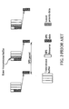
- FIG. 1 is a timing diagram illustrating a relationship between an allocated UL grant and an SR in dynamic scheduling according to the prior art.
- Tg time gap between a physical downlink control channel (PDCCH) UL grant and an actual UL transmission on a physical uplink shared channel (PUSCH), typically around 4ms in E-UTRAN.
- PDCCH physical downlink control channel
- PUSCH physical uplink shared channel
- Tg-Tp processing time
- BSR-SR a BSR and the associated SR, abbreviated to BSR-SR. If the total available data (new arriving data plus the existed data) in the transmission buffer could be accommodated in the upcoming allocated UL grant 1, the transmission buffer would be empty after the allocated UL grant 1, and the latter assigned UL grant 2 is therefore wasted. In this situation, BSR-SR triggering is unnecessary.
- FIG. 2 is a timing diagram illustrating a relationship between an allocated SPS UL resource and an SR according to the prior art.
- SPS data such as VolP data
- An assigned UL grant may arrive before or after an SPS resource, as a UL grant 1 or a UL grant 2 shown in FIG. 2 . If the UL grant comes before a certain SPS resource, the SPS data is transmitted in the UL grant 1 and the latter SPS resource is left empty. On the other hand, if the UL grant comes after the certain SPS resource, the SPS data is transmitted in the latter SPS resource and the UL grant 2 is left empty.
- the SR in the above situation is called a "premature SR".
- Premature SR also results from the fact that there is no guarantee that SPS data packets delivery is synchronized with periodic SPS resources. Generally, periodicity of SPS data delivery from a higher layer and periodicity of SPS resources are identical. Note that, when SPS data arrives at the transmission buffer, the UE needs a processing time to process the SPS data before it is actually transmitted. If the SPS data is ready for transmission at the TTI of SPS resource, i.e. the two processes are "synchronized”. If the SPS data does not catch the SPS resource, which is called "unsynchronized", the UE considers that it does not have an SPS UL resource allocated for the current TTI and a premature SR is triggered.
- FIG. 3 is a timing diagram illustrating a relationship between SPS resources and lower priority data according to the prior art. As shown in FIG. 3 , starvation for transmission of lower priority data happens when SPS data available for transmission is never emptied.
- the fourth issue is described as follows.
- the regular BSR is triggered when UL data arrives at the UE transmission buffer and the UL data belongs to a logical channel with higher priority than those for which data already existed in the UE transmission buffer, or is triggered when a serving cell change occurs.
- the periodic BSR is triggered when a periodic BSR timer expires.
- the padding BSR is triggered when UL resources are allocated and an amount of padding bits is equal to or greater than the size of the BSR MAC control element.
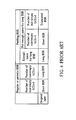
- FIG. 4 is a table of triggering events and corresponding BSR formats according to the prior art.
- Long BSR is used by regular BSR and periodic BSR if there are more than two logical channel groups (LCGs) having buffered data, and is used by padding BSR if the amount of padding bits is large enough.
- Short BSR is used by regular BSR and periodic BSR if there is only one LCG having buffered data, and is used by padding BSR if there is only one LCG having buffered data and the amount of padding bits is not large enough for long BSR.
- the truncated BSR is used by padding BSR when there are more than one LCG having buffered data and the amount of padding bits is not large enough for long BSR.
- the eNB Before SPS is introduced, there is no obstacle for the eNB to know the real buffer status of the UE through the current BSR mechanism. However, when SPS is configured, the current BSR mechanism becomes sub-optimal. For padding BSR in the current specification, when the number of non-empty LCG is greater than 1, the UE reports a truncated BSR of the LCG with the highest priority logical channel. When SPS is configured, the highest priority logical channel is usually SPS logical channel and therefore the truncated BSR would always report LCG of SPS logical channel. However, since the SPS resources are already allocated, most of time, the eNB does not really need that information.
- FIG. 5 is a timing diagram of a multiple-SPS-pattern scheme for TDD (Time Division Duplex) mode.
- the multiple-SPS-pattern scheme is designed to deal with frequent collision between initial transmissions and retransmissions. Two different intervals, T1 and T2, interchange with each other continuously and the sum of two intervals equals two times of the SPS period.
- SPS resource allocation in TDD mode meets the same problems, e.g. premature SR and starvation for transmission of lower priority data, as it in FDD (Frequency Division Duplex) mode.
- FIG. 6 is a schematic diagram of a wireless communication system 10 according to an embodiment of the present invention.
- the wireless communication system 10 is an LTE (long-term evolution) system or other mobile communication systems, and is briefly composed of a network and a plurality of user equipments (UEs).
- UEs user equipments
- the network and the UEs are simply utilized for illustrating the structure of the wireless communication system 10.
- the network may be an evolved universal terrestrial radio access network (E-UTRAN) comprising a plurality of evolved base stations (eNBs).
- E-UTRAN evolved universal terrestrial radio access network
- eNBs evolved base stations
- the UEs can be devices such as mobile phones, computer systems, etc.
- the network and the UE can be seen as a transmitter or receiver according to transmission direction, e.g., for uplink, the UE is the transmitter and the network is the receiver, and for downlink, the network is the transmitter and the UE is the receiver.
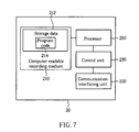
- FIG. 7 is a schematic diagram of a communication device 20 according to embodiments of the present invention.
- the communication device 20 can be the UE shown in FIG. 7 and includes a processor 200, a computer readable recording medium 210, a communication interfacing unit 220 and a control unit 230.
- the computer readable recording medium 210 is any data storage device that stores storage data 212, including program code 214, thereafter read and processed by the processor 200. Examples of the computer readable recording medium 210 include a subscriber identity module (SIM), read-only memory (ROM), random-access memory (RAM), CD-ROMs, magnetic tapes, floppy disks, optical data storage devices, and carrier waves (such as data transmission through the Internet).
- SIM subscriber identity module
- ROM read-only memory
- RAM random-access memory
- CD-ROMs compact discs
- magnetic tapes magnetic tapes
- floppy disks optical data storage devices
- optical data storage devices optical data storage devices
- carrier waves such as data transmission through the Internet
- FIG. 8 is a flowchart of a process 30 according to an embodiment of the present invention.
- the process 30 is utilized in a Media Access Control (MAC) layer in a UE in the wireless communication system 10 for solving the first issue and the second issue, for improving a trigger mechanism of BSR-SR.
- the process 30 can be compiled into the program code 214 and includes the following steps:
- the UE MAC first identifies whether the SPS resources are configured (which respectively corresponds to the situation of the first and the second issues).
- the total available data is the received first data plus data already existed in the transmission buffer.
- the first threshold is set to a specific value; for example, the first threshold is set to a size of the already allocated UL grant (bytes).
- the UE acknowledges the upcoming allocated UL grant but does not have a UL resource allocation for several TTIs before the allocated UL grant, and therefore the UE can set the first threshold after receiving the information of the upcoming allocated UL grant.
- Step 306 when the first data arrives at the transmission buffer when SPS resources are not configured, i.e., the first data is definitely not SPS data, the BSR-SR is triggered only when the size of the total available data in the transmission buffer is larger than the specific value as the size of the already allocated UL grant. Therefore, an associated BSR-SR is triggered under absolute necessary, which prevents from waste of UL grant.
- Step 308 on condition that the SPS resources are configured, when the type of the first data is data of SPS logical channel, called SPS data, the second threshold is set to a specific value, such as a size of an allocated SPS UL resource. If the SPS data arrives at the transmission buffer, the BSR-SR is triggered only when the size of the accumulated SPS data is larger than the size of the allocated SPS UL resource. In other words, the BSR-SR is triggered only when the allocated SPS resource are not enough.
- FIG. 9 is a timing diagram illustrating a relationship between SPS data and SPS resources according to the process 30. As shown in FIG.
- the allocated SPS resource is not enough so that a BSR-SR is triggered to request the eNB to assign a UL grant through dynamic scheduling for transmission of the SPS data burst.
- the BSR is usually transmitted with SPS data in the incoming SPS resource, and is not denoted in FIG. 9 .
- Step 306 and Step 308 can be integrated into a single step: decide a state of a BSR-SR triggering according to the state of SPS resource configuration, the type of the first data, and a comparison between a size of the second data in the transmission buffer and a threshold. Whether the second data is the total available data or the accumulated SPS data depends on the state of SPS resource configuration and the type of the first data. Besides, in order to use the threshold mechanism, the UE has to add required system parameter(s) to enable the use of the threshold.
- Step 310 when a pending SR exists, the UE further handles the pending SR according to a comparison between a size of the allocated UL grant corresponding to the BSR-SR and total available data in the transmission buffer.
- the allocated UL grant is enough to transmit the total available data existed in the transmission buffer, the pending SR is no longer necessary and is cancelled.
- the allocated UL grant is not enough to transmit the total available data, the pending SR is still useful for requesting another UL grant; therefore, the UE remains the pending SR.
- the MAC decides to trigger the BSR or not according to the state of SPS resource configuration, the type of the received first data and the threshold mechanism that performs the comparison between the size of the second data in the transmission buffer and the proper threshold. Therefore, the BSR-SR is triggered under absolute necessary and the UL resources are used more efficiently.
- the first threshold can be set according to the information of allocated UL grant previously.
- the threshold can be set based on UL grants information, for example, a size of a UL grant (whether it is a PDCCH UL grant or an SPS UL grant) or more than one UL grant, or combination of different kinds of UL grants, e.g. combination of SPS UL grants and PDCCH UL grants.
- the threshold can also be set according to UL sources in a predefined time window, e.g. next N subframes or SPS periods.
- the threshold can be set to a specific value by MAC or RRC, and the specific value may be predetermined in the system, in this way the threshold is not set according to any UL grant or time window.
- the BSR-SR triggering can be controlled based on per logical channel or per logical channel group (LCG) basis through the threshold mechanism.
- the separated logical channels can be assigned to a single LCG or not, and in this situation, the threshold(s) of the accumulated SPS data in the transmission buffer can be set for each logical channel or each LCG, depending on the type of control the UE intends.
- a threshold for the certain logical channel can be set to infinity by not allocating the logical channel to any LCG.
- the flexibility of the threshold mechanism depends on memory resources the UE allocated to store the threshold(s).
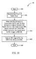
- FIG. 10 is a flowchart of a process 40 according to an embodiment of the present invention.
- the process 40 is utilized in the UE MAC when SPS resources are configured, for solving the third issue of stall of lower priority data, for improving a trigger mechanism of BSR-SR.
- the process 40 can be compiled into the program code 214 and includes the following steps: Step 400: : Start. Step 402: : Receive data from a higher layer.
- Step 404 When the data arrives at a transmission buffer and the data belongs to a logical channel with higher priority than those, except SPS logical channels, for which data already existed in the transmission buffer, trigger a BSR-SR.
- Step 406 Keep an SR triggered by the BSR from being cancelled.
- Step 408 End.
- the data belonging to a logical channel except SPS logical channels is called lower priority data.
- the UE MAC triggers the BSR-SR. Besides, the UE MAC keeps the SR triggered by the BSR from being cancelled, so that the eNB can receive the request for a UL grant for transmission of the lower priority data.
- FIG. 11 is a timing diagram illustrating a relationship between an allocated UL grant and lower priority data according to the process 40. As shown in FIG.
- the BSR-SR cannot be triggered when SPS data available for transmission is never emptied. Even if the process 30 is applied, the lower priority data still has no chance to be transmitted when accumulated SPS data in the transmission buffer is not over a threshold. Furthermore, periodic SPS transmissions may cancel the pending SR. In comparison, the process 40 not only triggers the BSR-SR when the lower priority data arrives but also allows the SR remaining even with the periodic SPS transmissions, and therefore the stall of non-SPS data is avoided.
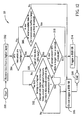
- FIG. 12 is a flowchart of a process 50 according to an embodiment of the present invention.
- the process 50 is utilized in the UE MAC and can be regarded as a combination of the processes 30 and 40 for solving the first issue, the second issue and the third issue.
- the process 50 can be compiled into the program code 214 and includes the following steps:
- a branch formed by Steps 504, 506 and 514 solves the first issue, as Step 304 and Step 306 of the process 30 do.
- a branch formed by Steps 504, 508, 510 and 514 solves the second issue, as Step 304 and Step 308 of the process 30 do.
- a branch formed by Step 504, 508, 512 and 514 solves the third issue, as the process 40 does.
- the first threshold used in Step 506 is set according to an allocated PDCCH UL grant
- the second threshold used in Step 510 is set according to an allocated SPS UL grant.
- the first threshold and the second threshold can also be set according to a size of UL grants or the sum of UL grants in a time window, which is described previously.
- FIG. 13 is a flowchart of a process 60 according to an embodiment of the present invention.
- the process 60 is utilized in the UE MAC for solving the second issue, for improving the trigger mechanism of BSR-SR when SPS resources are configured.
- the process 60 can be compiled into the program code 214 and includes the following steps:
- the MAC synchronizes the SPS data delivery from the higher layer, e.g. SPS application, and the SPS resources, so that the SPS data is ready to be transmitted with the destined SPS resources. Therefore, premature SRs are not triggered.
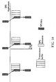
- FIG. 14 is a timing diagram illustrating a relationship between the SPS data delivery and the SPS resources according to the process 60. As shown in FIG. 14 , when the SPS data is delivered to the transmission buffer just a processing time Tp1 before next SPS resource, the SPS data can catch the SPS resources periodically, i.e. the SPS data delivery and the SPS resources are synchronized. Step 604 can be implemented by several ways as follows to achieve synchronization.
- One is the MAC sending an indication to the higher layer, which includes information of a time point that the higher layer has to deliver the SPS data, for the SPS data being ready for transmission at the TTIs of the SPS resources. If there is SPS data to be transmitted in the higher layer, the higher layer delivers the SPS data to the transmission buffer on the time point indicated by the indication; and if there is no SPS data to be transmitted in the higher layer, the higher layer just receives the indication and does not generate SPS data for the indication.
- FIG. 15(A) and FIG. 15(B) are schematic diagrams of implementations of the process 60.
- the MAC sends an indication IND just one processing time Tp1 before the SPS resource to inform the higher layer to deliver the SPS data now.
- the MAC can also send an indication IND to inform the higher layer to release the SPS data after t ms.
- t ms after sending the indication the UE still has enough processing time to process the SPS data such that the SPS data is just ready for transmission at the TTI of the SPS resource.
- the indication can be sent just once and the higher layer follows the setting in the indication to deliver SPS data.
- Another way is when the SPS data arrives at the transmission buffer, the MAC hiding the SPS data from a lower layer until TTIs of SPS resource arrival.
- the MAC uses a tag to hide the SPS data. As shown in FIG. 15(B) , the SPS data is delivered to the MAC much earlier than one processing time before the SPS resource and is hidden by the tag. The SPS data becomes visible when the SPS resource is available and therefore the SPS data catches the SPS resource.
- the unsynchronization of the SPS data delivery and the SPS resource results in unnecessary BSR-SR triggering.
- the SPS data is delivered to the transmission buffer at least one processing time before the TTI of the SPS resource, so that the SPS data catch the SPS resource. Therefore, a premature SR is not triggered.
- FIG. 16 is a flowchart of a process 70 according to an embodiment of the present invention.
- the process 70 is utilized in the UE MAC for solving the fourth issue, for improving the trigger mechanism of BSR-SR when SPS resources are configured.
- the process 70 can be compiled into the program code 214 and includes the following steps:
- Step 702 modifies the use of the truncated BSR such that the MAC can report with the truncated BSR format with necessary LCG information to the eNB.
- the threshold mechanism introduced previously is applied to the process 70, to help the MAC to make the right decision for what kind of LCG the truncated BSR should report.
- Step 702 is detailed described as follow.
- the UE MAC makes the truncated BSR format to report the LCG with the highest priority logical channel excluding SPS logical channels when the size of the accumulated SPS data in the transmission buffer is smaller than the threshold.
- the UE MAC makes the truncated BSR format to report the LCG with SPS logical channel(s) when the size of the accumulated SPS data in the transmission buffer is larger than the threshold, which means that the allocated SPS UL resources are not enough for transmission and the eNB really needs to know the report of the LCG.
- the first logical channel in Step 702 is the highest priority channel excluding the SPS logical channel or is just SPS logical channel depends on the comparison between the size of accumulated SPS data and the threshold.
- the threshold in the process 70 is similar to the second threshold in the process 30, and can be set to a specific value, such as a size of an allocated UL grant or more than one UL grant, or set according to the sum of uplink grants during a time window. Furthermore, the threshold can also be set to a predetermined value not according to any UL grant or time window.
- the UE when the SPS resources are configured, the UE still uses the truncated BSR format to report LCG with the highest priority logical channel, the SPS logical channel, which is probably unnecessary information for the eNB when allocated SPS resource is large enough.
- the present invention applies the threshold mechanism to determine if the truncated BSR format reports the LCG with the SPS logical channel(s) or the LCG with the highest priority logical channel(s) excluding SPS logical channel(s). Therefore, the condition of reporting the truncated BSR is improved and the UE does not report unnecessary LCG information of SPS logical channel to the eNB.
- SPS resource allocation in TDD (Time Division Duplex) mode meets the same problems, e.g. premature SR and starvation for transmission of lower priority data, as in FDD (Frequency Division Duplex) mode.
- the threshold mechanism for SPS introduced as above are designed based on FDD mode, and can also be applied in TDD mode with a threshold designed for TDD. Please refer to FIG. 5 again. As shown in FIG. 5 , T2 is short. If the UL resource 1 cannot accommodate SPS data available for transmission in the transmission buffer, the UE does not really need to trigger an SR and just waits until next UL resource 2 arriving because T2 is short.
- the threshold is set according to a time window such that the UL resource 2 is included in the threshold; or, the threshold is set according to two times of the data which could be transmitted in a single SPS resource.
- the threshold setting is similar to those mentioned previously and is not repeated. Besides, even though conflict between the TDD UL/DL configuration and SPS resource configuration may occur and results in cancelled SPS UL resources, the UE can predict such conflict occurrence and modify threshold accordingly.
Landscapes
- Engineering & Computer Science (AREA)
- Computer Networks & Wireless Communication (AREA)
- Signal Processing (AREA)
- Databases & Information Systems (AREA)
- Mobile Radio Communication Systems (AREA)
Abstract
Description
- The present invention relates to a method and related communication device of a trigger mechanism of buffer status report, abbreviated to BSR, and scheduling request, abbreviated to SR, in a wireless communication system.
- A long-term evolution (LTE) system, initiated by the third generation partnership project (3GPP), is now being regarded as a new radio interface and radio network architecture that provides a high data rate, low latency, packet optimization, and improved system capacity and coverage. In the LTE system, an evolved universal terrestrial radio access network (E-UTRAN) includes a plurality of evolved Node-Bs (eNBs) and communicates with a plurality of mobile stations, also referred as user equipments (UEs).
- In the 3GPP associated specifications, logical channels are defined as service access points between a Media Access Control (MAC) layer and a Radio Link Control (RLC) layer. The MAC provides data transfer services on logical channels. Each logical channel type is defined by the type of information to be transferred. A Radio Resource Control (RRC) layer can control the scheduling of uplink data by giving each logical channel a priority.
- According to the current 3GPP MAC specification, a buffer status reporting procedure is used to provide information about the size of data in uplink (UL) buffers of a UE for a serving eNB. A buffer status report (BSR) is triggered when UL data belonging to a logical channel with higher priority than those for which data already existed in the UE transmission buffer arrives at a UE transmission buffer. In addition, a scheduling request (SR) is used to request UL resources. The SR is triggered when the UE does not have a UL resource allocated for the current transmission time interval (TTI), which implies that a dedicated SR (D-SR) is transmitted on the physical uplink control channel (PUCCH) if the UL resource is allocated to the UE, or alternatively a random access SR (RA-SR) is transmitted on the random access channel (RACH). The pending SR is cancelled when new resources are available on UL-SCH, which is granted by eNB through dynamically scheduling.
- In order to utilize shared channel (SCH) resources, a dynamic scheduling (DS) function is used in MAC. When sharing resources between UEs, MAC in eNB dynamically allocates physical layer resources for the DL-SCH and UL-SCH depends on the traffic volume, the QoS requirements of each UE and associated radio bearers. On the other hand, a semi-persistent scheduling (SPS) is introduced in LTE system and is also used in MAC for serving upper layer applications which generates semi-static size data periodically, e.g. VoIP services. SPS is more efficient than DS for VolP data transmission.
- LG ELECTRONICS INC: "BSR for Persistent Scheduling" 3GPP DRAFT; R2-081070, 3RD GENERATION PARTNERSHIP PROJECT (3GPP), MOBILE COMPETENCE CENTRE, 650, ROUTE DES LUCIOLES, F-06921 SOPHIA-ANTIPOLIS CEDEX, FRANCE, RAN WG2, Sorrento, Italy; 5 February 2008, XP050138859 relates to BSR for persistent scheduling and was used as a basis for the preamble of the
independent claims 1 and 5. - This in mind, the present invention aims at providing a method and related communication device of a trigger mechanism of BSR and SR that uses a threshold to decide when to trigger a BSR-SR in a wireless communication system.
- This is achieved by a method and related communication device of a trigger mechanism of BSR and SR in a wireless communication system according to
claims 1 and5. The dependent claims pertain to corresponding further developments and improvements. - In the following, the invention is further illustrated by way of example, taking reference to the accompanying drawings. Thereof
-
FIG. 1 is a timing diagram illustrating a relationship between an allocated UL grant and an SR in dynamic scheduling according to the prior art. -
FIG. 2 is a timing diagram illustrating a relationship between an allocated SPS UL resource and an SR according to the prior art. -
FIG. 3 is a timing diagram illustrating a relationship between SPS resources and lower priority data according to the prior art. -
FIG. 4 is a table of triggering events and corresponding BSR formats according to the prior art. -
FIG. 5 is a timing diagram of a multiple-SPS-patterns scheme for TDD mode. -
FIG. 6 is a schematic diagram of a wireless communication system. -
FIG. 7 is a schematic diagram of a communication device according to embodiments of the present invention. -
FIG. 8 is flowchart of a process according to an embodiment of the present invention. -
FIG. 9 is a timing diagram illustrating a relationship between SPS data and SPS resources according to the process inFIG. 8 . -
FIG. 10 is a flowchart of a process according to an embodiment of the present invention. -
FIG. 11 is a timing diagram illustrating a relationship between an allocated UL grant and lower priority data according to the process inFIG. 10 . -
FIG. 12 is a flowchart of a related process. -
FIG. 13 is a flowchart of a related process. -
FIG. 14 is a timing diagram illustrating a relationship between the SPS data delivery and the SPS resources according to the process inFIG. 13 . -
FIG. 15(A) and FIG. 15(B) are schematic diagrams of implementations of the process inFIG. 13 . -
FIG. 16 is a flowchart of a related process. - According to the current UE MAC specification, an SR is triggered without considering the already allocated UL grant requested through DS or assigned by SPS. Only the current TTI is considered when making the decision of triggering the SR. This UE behavior results in several issues illustrated in
FIG. 1 to FIG. 5 , and are described as follows. - The first issue is described as follows. Please refer to
FIG. 1 , which is a timing diagram illustrating a relationship between an allocated UL grant and an SR in dynamic scheduling according to the prior art. InFIG. 1 , there is a time gap Tg between a physical downlink control channel (PDCCH) UL grant and an actual UL transmission on a physical uplink shared channel (PUSCH), typically around 4ms in E-UTRAN. In other words, when a UL grant is received in subframe n, the actual UL transmission takes place in subframe (n+4). After receiving a PDCCH UL grant, the UE decodes and processes the received information, which takes a processing time Tp, normally less than 2ms. Therefore, there is a window with a length (Tg-Tp) in which the UE acknowledges the upcoming allocatedUL grant 1 but does not have a UL resource allocation for several TTIs before theupcoming UL grant 1. - During this window, if new UL data arrives at a transmission buffer and the new UL data belongs to a logical channel with higher priority than those for which data already existed in the transmission buffer, a BSR and the associated SR, abbreviated to BSR-SR, is triggered. If the total available data (new arriving data plus the existed data) in the transmission buffer could be accommodated in the upcoming allocated
UL grant 1, the transmission buffer would be empty after the allocatedUL grant 1, and the latter assignedUL grant 2 is therefore wasted. In this situation, BSR-SR triggering is unnecessary. - When SPS resources are configured, the second issue happens and is described as follows. Please refer to
FIG. 2 , which is a timing diagram illustrating a relationship between an allocated SPS UL resource and an SR according to the prior art. As shown inFIG. 2 , SPS data, such as VolP data, enters the transmission buffer and an SR is generated. An assigned UL grant may arrive before or after an SPS resource, as aUL grant 1 or aUL grant 2 shown inFIG. 2 . If the UL grant comes before a certain SPS resource, the SPS data is transmitted in theUL grant 1 and the latter SPS resource is left empty. On the other hand, if the UL grant comes after the certain SPS resource, the SPS data is transmitted in the latter SPS resource and theUL grant 2 is left empty. The SR in the above situation is called a "premature SR". - Premature SR also results from the fact that there is no guarantee that SPS data packets delivery is synchronized with periodic SPS resources. Generally, periodicity of SPS data delivery from a higher layer and periodicity of SPS resources are identical. Note that, when SPS data arrives at the transmission buffer, the UE needs a processing time to process the SPS data before it is actually transmitted. If the SPS data is ready for transmission at the TTI of SPS resource, i.e. the two processes are "synchronized". If the SPS data does not catch the SPS resource, which is called "unsynchronized", the UE considers that it does not have an SPS UL resource allocated for the current TTI and a premature SR is triggered.
- In accordance with the first issue and the second issue, it is known that wasting an allocated UL grant results in unnecessary BSR-SR triggering and inefficient use of UL resources. Moreover, the problem deteriorates in the presence of SPS, which is designed for time-critical applications.
- The third issue is described as follows. Note that when SPS resources are configured, data belonging to a logical channel except SPS logical channels is called lower priority data. According to the current specification, when lower priority data arrives at the transmission buffer, a BSR is not triggered when SPS data available for transmission is never emptied and simply sits in the transmission buffer. As a result, the potential starvation for transmission of the lower priority data may happen.
- Besides, in the current MAC specification, a pending SR shall be cancelled until UL-SCH resources are granted for a new transmission. It is not clear whether these UL-SCH resources for new transmission include periodic new SPS transmissions without any PDCCH assignment. If periodic SPS transmissions would cancel the pending SR, the short-lived SR may be cancelled prematurely, and even worse, cancelled periodically. Please refer to
FIG. 3 , which is a timing diagram illustrating a relationship between SPS resources and lower priority data according to the prior art. As shown inFIG. 3 , starvation for transmission of lower priority data happens when SPS data available for transmission is never emptied. - The fourth issue is described as follows. There are three types of BSRs for different triggering events, a regular BSR, a periodic BSR and a padding BSR. The regular BSR is triggered when UL data arrives at the UE transmission buffer and the UL data belongs to a logical channel with higher priority than those for which data already existed in the UE transmission buffer, or is triggered when a serving cell change occurs. The periodic BSR is triggered when a periodic BSR timer expires. The padding BSR is triggered when UL resources are allocated and an amount of padding bits is equal to or greater than the size of the BSR MAC control element.
- Besides, there are three types of BSR format, long, short, and truncated BSR. Please refer to
FIG. 4 , which is a table of triggering events and corresponding BSR formats according to the prior art. Long BSR is used by regular BSR and periodic BSR if there are more than two logical channel groups (LCGs) having buffered data, and is used by padding BSR if the amount of padding bits is large enough. Short BSR is used by regular BSR and periodic BSR if there is only one LCG having buffered data, and is used by padding BSR if there is only one LCG having buffered data and the amount of padding bits is not large enough for long BSR. The truncated BSR is used by padding BSR when there are more than one LCG having buffered data and the amount of padding bits is not large enough for long BSR. - Before SPS is introduced, there is no obstacle for the eNB to know the real buffer status of the UE through the current BSR mechanism. However, when SPS is configured, the current BSR mechanism becomes sub-optimal. For padding BSR in the current specification, when the number of non-empty LCG is greater than 1, the UE reports a truncated BSR of the LCG with the highest priority logical channel. When SPS is configured, the highest priority logical channel is usually SPS logical channel and therefore the truncated BSR would always report LCG of SPS logical channel. However, since the SPS resources are already allocated, most of time, the eNB does not really need that information.
- The fifth issue is described as follows. Please refer to
FIG. 5 , which is a timing diagram of a multiple-SPS-pattern scheme for TDD (Time Division Duplex) mode. The multiple-SPS-pattern scheme is designed to deal with frequent collision between initial transmissions and retransmissions. Two different intervals, T1 and T2, interchange with each other continuously and the sum of two intervals equals two times of the SPS period. - Therefore, even though the average SPS UL resource is still one per SPS period, the separation between adjacent SPS resources is not identical anymore. Another way to understand is there are two patterns sharing the same period but being initiated at different times. SPS resource allocation in TDD mode meets the same problems, e.g. premature SR and starvation for transmission of lower priority data, as it in FDD (Frequency Division Duplex) mode.
- Please refer to
FIG. 6 , which is a schematic diagram of awireless communication system 10 according to an embodiment of the present invention. Thewireless communication system 10 is an LTE (long-term evolution) system or other mobile communication systems, and is briefly composed of a network and a plurality of user equipments (UEs). InFIG. 6 , the network and the UEs are simply utilized for illustrating the structure of thewireless communication system 10. Practically, the network may be an evolved universal terrestrial radio access network (E-UTRAN) comprising a plurality of evolved base stations (eNBs). The UEs can be devices such as mobile phones, computer systems, etc. Besides, the network and the UE can be seen as a transmitter or receiver according to transmission direction, e.g., for uplink, the UE is the transmitter and the network is the receiver, and for downlink, the network is the transmitter and the UE is the receiver. - Please refer to
FIG. 7 , which is a schematic diagram of acommunication device 20 according to embodiments of the present invention. Thecommunication device 20 can be the UE shown inFIG. 7 and includes aprocessor 200, a computerreadable recording medium 210, acommunication interfacing unit 220 and acontrol unit 230. The computerreadable recording medium 210 is any data storage device that storesstorage data 212, includingprogram code 214, thereafter read and processed by theprocessor 200. Examples of the computerreadable recording medium 210 include a subscriber identity module (SIM), read-only memory (ROM), random-access memory (RAM), CD-ROMs, magnetic tapes, floppy disks, optical data storage devices, and carrier waves (such as data transmission through the Internet). Thecontrol unit 230 controls thecommunication interfacing unit 220 and related operations and states of thecommunication device 20 according to processing results of theprocess 200. Thecommunication interfacing unit 220 is preferably a radio transceiver for wirelessly communicating with the network. - As the first issue mentioned previously, a scheduling request (SR) is triggered without considering the already allocated UL grant requested through dynamic scheduling (DS). In the second issue, when the eNB configures semi-persistent scheduling (SPS) resources for the UE, a premature SR is triggered without considering already allocated SPS UL resources. The first and the second issues both result in waste of a PDCCH UL grant or a SPS UL resource. Please refer to
FIG. 8 , which is a flowchart of aprocess 30 according to an embodiment of the present invention. Theprocess 30 is utilized in a Media Access Control (MAC) layer in a UE in thewireless communication system 10 for solving the first issue and the second issue, for improving a trigger mechanism of BSR-SR. Theprocess 30 can be compiled into theprogram code 214 and includes the following steps: - Step 300: : Start.
- Step 302: : Receive a first data from a higher layer.
- Step 304: : When the first data arrives at a transmission buffer, identify a state of SPS resource configuration and a type of the first data. If SPS resources are not configured, perform
Step 306; else, performStep 308. - Step 306: : When a size of total available data in the transmission buffer is larger than a first threshold, trigger a BSR-SR.
- Step 308: : When the type of the first data is SPS data and a size of accumulated SPS data in the transmission buffer is larger than a second threshold, trigger a BSR-SR.
- Step 310: : After a BSR-SR is triggered, handle a pending SR according to a comparison between a size of an uplink grant corresponding to the BSR-SR and total available data in the transmission buffer, when the pending SR exists.
- Step 312: : End.
- According to the
process 30, when the first data arrives, the UE MAC first identifies whether the SPS resources are configured (which respectively corresponds to the situation of the first and the second issues). InStep 306, on condition that the SPS resources are not configured, the total available data is the received first data plus data already existed in the transmission buffer. The first threshold is set to a specific value; for example, the first threshold is set to a size of the already allocated UL grant (bytes). As mentioned previously, there is a window in which the UE acknowledges the upcoming allocated UL grant but does not have a UL resource allocation for several TTIs before the allocated UL grant, and therefore the UE can set the first threshold after receiving the information of the upcoming allocated UL grant. There are several ways to set the first threshold and are introduced later. - According to
Step 306, when the first data arrives at the transmission buffer when SPS resources are not configured, i.e., the first data is definitely not SPS data, the BSR-SR is triggered only when the size of the total available data in the transmission buffer is larger than the specific value as the size of the already allocated UL grant. Therefore, an associated BSR-SR is triggered under absolute necessary, which prevents from waste of UL grant. - On the other hand, in
Step 308, on condition that the SPS resources are configured, when the type of the first data is data of SPS logical channel, called SPS data, the second threshold is set to a specific value, such as a size of an allocated SPS UL resource. If the SPS data arrives at the transmission buffer, the BSR-SR is triggered only when the size of the accumulated SPS data is larger than the size of the allocated SPS UL resource. In other words, the BSR-SR is triggered only when the allocated SPS resource are not enough. Please refer toFIG. 9 , which is a timing diagram illustrating a relationship between SPS data and SPS resources according to theprocess 30. As shown inFIG. 9 , the allocated SPS resource is not enough so that a BSR-SR is triggered to request the eNB to assign a UL grant through dynamic scheduling for transmission of the SPS data burst. Note that, the BSR is usually transmitted with SPS data in the incoming SPS resource, and is not denoted inFIG. 9 . - From the above, the present invention uses a threshold mechanism to deicide to trigger a BSR-SR or not. When the first data arrives at the transmission buffer, different thresholds are used according to whether the SPS resources are configured and what type of the first data is. In other words, Step 306 and
Step 308 can be integrated into a single step: decide a state of a BSR-SR triggering according to the state of SPS resource configuration, the type of the first data, and a comparison between a size of the second data in the transmission buffer and a threshold. Whether the second data is the total available data or the accumulated SPS data depends on the state of SPS resource configuration and the type of the first data. Besides, in order to use the threshold mechanism, the UE has to add required system parameter(s) to enable the use of the threshold. - After the BSR-SR is triggered for requesting UL grant, according to
Step 310, when a pending SR exists, the UE further handles the pending SR according to a comparison between a size of the allocated UL grant corresponding to the BSR-SR and total available data in the transmission buffer. When the allocated UL grant is enough to transmit the total available data existed in the transmission buffer, the pending SR is no longer necessary and is cancelled. When the allocated UL grant is not enough to transmit the total available data, the pending SR is still useful for requesting another UL grant; therefore, the UE remains the pending SR. - In the prior art, when data arrives at the transmission buffer, only UL resource allocated for the current TTI is considered when the UE makes the decision of triggering a BSR, whether SPS resources are configured. As a result, an unnecessary BSR-SR is triggered and an assigned UL grant or an SPS resource is wasted. According to the above-mentioned embodiment of the present invention, when data arrives at the transmission buffer, the MAC decides to trigger the BSR or not according to the state of SPS resource configuration, the type of the received first data and the threshold mechanism that performs the comparison between the size of the second data in the transmission buffer and the proper threshold. Therefore, the BSR-SR is triggered under absolute necessary and the UL resources are used more efficiently.
- There are several ways to set the threshold in the
process 30. The first threshold can be set according to the information of allocated UL grant previously. The threshold can be set based on UL grants information, for example, a size of a UL grant (whether it is a PDCCH UL grant or an SPS UL grant) or more than one UL grant, or combination of different kinds of UL grants, e.g. combination of SPS UL grants and PDCCH UL grants. The threshold can also be set according to UL sources in a predefined time window, e.g. next N subframes or SPS periods. Furthermore, the threshold can be set to a specific value by MAC or RRC, and the specific value may be predetermined in the system, in this way the threshold is not set according to any UL grant or time window. - In addition, the BSR-SR triggering can be controlled based on per logical channel or per logical channel group (LCG) basis through the threshold mechanism. For example, when there are more than one SPS service configured on separated logical channels, the separated logical channels can be assigned to a single LCG or not, and in this situation, the threshold(s) of the accumulated SPS data in the transmission buffer can be set for each logical channel or each LCG, depending on the type of control the UE intends. In the situation that the UE simply does not want data belonging to a certain logical channel to trigger a BSR-SR or to be included in a BSR, a threshold for the certain logical channel can be set to infinity by not allocating the logical channel to any LCG. The flexibility of the threshold mechanism depends on memory resources the UE allocated to store the threshold(s).
- As the third issue mentioned previously, if the SPS resources are configured, lower priority data cannot trigger a BSR and simply sits in the transmission buffer. Please refer to
FIG. 10 , which is a flowchart of aprocess 40 according to an embodiment of the present invention. Theprocess 40 is utilized in the UE MAC when SPS resources are configured, for solving the third issue of stall of lower priority data, for improving a trigger mechanism of BSR-SR. Theprocess 40 can be compiled into theprogram code 214 and includes the following steps:
Step 400: : Start.
Step 402: : Receive data from a higher layer.
Step 404: : When the data arrives at a transmission buffer and the data belongs to a logical channel with higher priority than those, except SPS logical channels, for which data already existed in the transmission buffer, trigger a BSR-SR.
Step 406: : Keep an SR triggered by the BSR from being cancelled.
Step 408: : End. - The data belonging to a logical channel except SPS logical channels is called lower priority data. According to the
process 40, on condition that the SPS resources are configured, when the arriving lower priority data belongs to a logical channel with higher priority than those, except SPS logical channels, for which data already existed in the transmission buffer, the UE MAC triggers the BSR-SR. Besides, the UE MAC keeps the SR triggered by the BSR from being cancelled, so that the eNB can receive the request for a UL grant for transmission of the lower priority data. Please refer toFIG. 11 , which is a timing diagram illustrating a relationship between an allocated UL grant and lower priority data according to theprocess 40. As shown inFIG. 11 , when lower priority data arrives, a BSR-SR is triggered even if there is SPS data available for transmission, and the SR is not cancelled by new SPS transmission. Finally, the eNB assigns a UL grant and the lower priority data is therefore transmitted instead of staying in the transmission buffer. - In the prior art, when the lower priority data arrives, the BSR-SR cannot be triggered when SPS data available for transmission is never emptied. Even if the
process 30 is applied, the lower priority data still has no chance to be transmitted when accumulated SPS data in the transmission buffer is not over a threshold. Furthermore, periodic SPS transmissions may cancel the pending SR. In comparison, theprocess 40 not only triggers the BSR-SR when the lower priority data arrives but also allows the SR remaining even with the periodic SPS transmissions, and therefore the stall of non-SPS data is avoided. - Please refer to
FIG. 12 , which is a flowchart of aprocess 50 according to an embodiment of the present invention. Theprocess 50 is utilized in the UE MAC and can be regarded as a combination of theprocesses process 50 can be compiled into theprogram code 214 and includes the following steps: - Step 500: : Start.
- Step 502: : Receive data from a higher layer.
- Step 504: : When the data arrives at a transmission buffer, identify whether SPS resources are configured. If the SPS resources are not configured, perform
Step 506; else, performStep 508. - Step 506: : If a size of total available data in the transmission buffer is larger than a first threshold, perform
Step 514; else, performStep 516. - Step 508: : identify whether a type of the data is SPS data. If the type of the data is SPS data, perform
Step 510; else, performStep 512. - Step 510: : If a size of accumulated SPS data is larger than a second threshold, perform
Step 514; else, performStep 516. - Step 512: : If the data belongs to a logical channel with higher priority than those, except SPS logical channels, for which data already existed in the transmission buffer, perform
Step 514; else, performStep 516. - Step 514: : Trigger a BSR-SR.
- Step 516: : Do not trigger a BSR-SR.
- Step 518: : End.
- A branch formed by
Steps Step 304 and Step 306 of theprocess 30 do. A branch formed bySteps Step 304 and Step 308 of theprocess 30 do. A branch formed byStep process 40 does. In theprocess 50, the first threshold used inStep 506 is set according to an allocated PDCCH UL grant, and the second threshold used inStep 510 is set according to an allocated SPS UL grant. The first threshold and the second threshold can also be set according to a size of UL grants or the sum of UL grants in a time window, which is described previously. - In addition, the second issue can be solved by a synchronization mechanism introduced as follows instead of the threshold mechanism. Please refer to
FIG. 13 , which is a flowchart of aprocess 60 according to an embodiment of the present invention. Theprocess 60 is utilized in the UE MAC for solving the second issue, for improving the trigger mechanism of BSR-SR when SPS resources are configured. Theprocess 60 can be compiled into theprogram code 214 and includes the following steps: - Step 600: : Start.
- Step 602: : Receive SPS data from a higher layer.
- Step 604: : Synchronize the SPS data delivery and SPS resources arrival, for the SPS data being ready for transmission at the TTIs of the SPS resources.
- Step 606: : End.
- According to the
process 60, the MAC synchronizes the SPS data delivery from the higher layer, e.g. SPS application, and the SPS resources, so that the SPS data is ready to be transmitted with the destined SPS resources. Therefore, premature SRs are not triggered. Please refer toFIG. 14 , which is a timing diagram illustrating a relationship between the SPS data delivery and the SPS resources according to theprocess 60. As shown inFIG. 14 , when the SPS data is delivered to the transmission buffer just a processing time Tp1 before next SPS resource, the SPS data can catch the SPS resources periodically, i.e. the SPS data delivery and the SPS resources are synchronized. Step 604 can be implemented by several ways as follows to achieve synchronization. - One is the MAC sending an indication to the higher layer, which includes information of a time point that the higher layer has to deliver the SPS data, for the SPS data being ready for transmission at the TTIs of the SPS resources. If there is SPS data to be transmitted in the higher layer, the higher layer delivers the SPS data to the transmission buffer on the time point indicated by the indication; and if there is no SPS data to be transmitted in the higher layer, the higher layer just receives the indication and does not generate SPS data for the indication.
- For example, please refer to
FIG. 15(A) and FIG. 15(B) , which are schematic diagrams of implementations of theprocess 60. InFIG. 15(A) , the MAC sends an indication IND just one processing time Tp1 before the SPS resource to inform the higher layer to deliver the SPS data now. Besides, the MAC can also send an indication IND to inform the higher layer to release the SPS data after t ms. Then, t ms after sending the indication, the UE still has enough processing time to process the SPS data such that the SPS data is just ready for transmission at the TTI of the SPS resource. Note that, the indication can be sent just once and the higher layer follows the setting in the indication to deliver SPS data. - Another way is when the SPS data arrives at the transmission buffer, the MAC hiding the SPS data from a lower layer until TTIs of SPS resource arrival. The MAC uses a tag to hide the SPS data. As shown in
FIG. 15(B) , the SPS data is delivered to the MAC much earlier than one processing time before the SPS resource and is hidden by the tag. The SPS data becomes visible when the SPS resource is available and therefore the SPS data catches the SPS resource. - As the second issue mentioned previously, when SPS resources are configured, the unsynchronization of the SPS data delivery and the SPS resource results in unnecessary BSR-SR triggering. In comparison, according to the
process 60, whatever an indication or a tag is used, the SPS data is delivered to the transmission buffer at least one processing time before the TTI of the SPS resource, so that the SPS data catch the SPS resource. Therefore, a premature SR is not triggered. - As the fourth issue mentioned previously, when SPS is introduced in the specifications, if SPS resources are configured, the eNB does not really need the information reported by the truncated BSR because the highest priority logical channel is SPS logical channel. Please refer to
FIG. 16 , which is a flowchart of aprocess 70 according to an embodiment of the present invention. Theprocess 70 is utilized in the UE MAC for solving the fourth issue, for improving the trigger mechanism of BSR-SR when SPS resources are configured. Theprocess 70 can be compiled into theprogram code 214 and includes the following steps: - Step 700: : Start.
- Step 702: : Make truncated BSR format to report an LCG with a first logical channel which is decided according to a comparison between a size of accumulated SPS data in a transmission buffer and a threshold.
- Step 704: : Report a padding BSR with the truncated BSR format when an amount of padding bits is not enough for long BSR format and more than one LCG has buffered data.
- Step 706: : End.
- Step 702 modifies the use of the truncated BSR such that the MAC can report with the truncated BSR format with necessary LCG information to the eNB. Note that the threshold mechanism introduced previously is applied to the
process 70, to help the MAC to make the right decision for what kind of LCG the truncated BSR should report. Step 702 is detailed described as follow. The UE MAC makes the truncated BSR format to report the LCG with the highest priority logical channel excluding SPS logical channels when the size of the accumulated SPS data in the transmission buffer is smaller than the threshold. Moreover, the UE MAC makes the truncated BSR format to report the LCG with SPS logical channel(s) when the size of the accumulated SPS data in the transmission buffer is larger than the threshold, which means that the allocated SPS UL resources are not enough for transmission and the eNB really needs to know the report of the LCG. Whether the first logical channel inStep 702 is the highest priority channel excluding the SPS logical channel or is just SPS logical channel depends on the comparison between the size of accumulated SPS data and the threshold. Note that the threshold in theprocess 70 is similar to the second threshold in theprocess 30, and can be set to a specific value, such as a size of an allocated UL grant or more than one UL grant, or set according to the sum of uplink grants during a time window. Furthermore, the threshold can also be set to a predetermined value not according to any UL grant or time window. - According to the current specification, when the SPS resources are configured, the UE still uses the truncated BSR format to report LCG with the highest priority logical channel, the SPS logical channel, which is probably unnecessary information for the eNB when allocated SPS resource is large enough. In comparison, the present invention applies the threshold mechanism to determine if the truncated BSR format reports the LCG with the SPS logical channel(s) or the LCG with the highest priority logical channel(s) excluding SPS logical channel(s). Therefore, the condition of reporting the truncated BSR is improved and the UE does not report unnecessary LCG information of SPS logical channel to the eNB.
- As the fifth issue mentioned previously, SPS resource allocation in TDD (Time Division Duplex) mode meets the same problems, e.g. premature SR and starvation for transmission of lower priority data, as in FDD (Frequency Division Duplex) mode. The threshold mechanism for SPS introduced as above are designed based on FDD mode, and can also be applied in TDD mode with a threshold designed for TDD. Please refer to
FIG. 5 again. As shown inFIG. 5 , T2 is short. If theUL resource 1 cannot accommodate SPS data available for transmission in the transmission buffer, the UE does not really need to trigger an SR and just waits untilnext UL resource 2 arriving because T2 is short. In other words, the threshold is set according to a time window such that theUL resource 2 is included in the threshold; or, the threshold is set according to two times of the data which could be transmitted in a single SPS resource. The threshold setting is similar to those mentioned previously and is not repeated. Besides, even though conflict between the TDD UL/DL configuration and SPS resource configuration may occur and results in cancelled SPS UL resources, the UE can predict such conflict occurrence and modify threshold accordingly.
Claims (8)
- A method of a trigger mechanism of buffer status report, BSR, and scheduling request, SR, for a media access control, MAC, layer of a user equipment, UE, in a communication system, the method comprising:receiving a first data (302);identifying a state of semi-persistent scheduling, SPS, resource configuration and a type of the first data when the first data arrives at a transmission buffer (304); anddeciding a state of a BSR-SR triggering according to the state of SPS resource configuration, the type of the first data, and a comparison between a size of a second data in the transmission buffer and a threshold;characterized byafter a BSR-SR is triggered, cancelling a pending SR when an uplink grant corresponding to the BSR-SR is enough to transmit total available data in the transmission buffer, or retaining the pending SR when an uplink grant corresponding to the BSR-SR is not enough to transmit the total available data in the transmission buffer.
- The method of claim 1, characterized in that the step of deciding the state of the BSR-SR triggering comprises at least one of the following:when SPS resources are not configured and a size of total available data in the transmission buffer is larger than the threshold, triggering the BSR-SR, wherein the total available data is the second data equal to the first data plus the data already existed in transmission buffer (306); andwhen the SPS resources are configured, the first data is SPS data, and a size of accumulated SPS data in the transmission buffer is larger than the threshold, triggering the BSR-SR, wherein the accumulated SPS data is the second data (308).
- The method of claim 1, characterized in that the threshold is set to a value according to a size of at least one uplink grant, a value according to the sum of uplink grants during a time window, or a predetermined value not according to any uplink grant or time window.
- The method of claim 1, characterized in that the threshold for a logical channel is set to infinity by not allocating the logical channel to any logical channel group.
- A communication device (20) of a wireless communication system for a trigger mechanism of buffer status report, BSR, and scheduling request, SR, for a media access control, MAC, layer, the communication device (20) comprising:a computer readable recording medium (210) for storing program code (214) corresponding to a process (30); anda processor (200) coupled to the computer readable recording medium (210), for processing the program code (214) to execute the process (30), wherein the process (30) comprises:receiving a first data (302);identifying a state of semi-persistent scheduling, abbreviated to SPS,resource configuration and a type of the first data when the first data arrives at a transmission buffer (304); anddeciding a state of a BSR-SR triggering according to the state of SPS resource configuration, the type of the first data, and a comparison between a size of a second data in the transmission buffer and a threshold;characterized byafter a BSR-SR is triggered, cancelling a pending SR when an uplink grant corresponding to the BSR-SR is enough to transmit total available data in the transmission buffer, or retaining the pending SR when an uplink grant corresponding to the BSR-SR is not enough to transmit the total available data in the transmission buffer.
- The communication device of claim 5, characterized in that the step of deciding the state of the BSR-SR triggering in the process comprises at least one of the following:when SPS resources are not configured and a size of total available data in the transmission buffer is larger than the threshold, triggering the BSR-SR, wherein the total available data is the second data equal to the first data plus the data already existed in transmission buffer (306); andwhen the SPS resources are configured, the first data is SPS data, and a size of accumulated SPS data in the transmission buffer is larger than the threshold, triggering the BSR-SR, wherein the accumulated SPS data is the second data (308).
- The communication device of claim 5, characterized in that the threshold is set to a value according to a size of at least one uplink grant, a value according to the sum of uplink grants during a time window, or a predetermined value not according to any uplink grant or time window.
- The communication device of claim 5, characterized in that the threshold for a logical channel is set to infinity by not allocating the logical channel to any logical channel group.
Applications Claiming Priority (2)
| Application Number | Priority Date | Filing Date | Title |
|---|---|---|---|
| US9880108P | 2008-09-22 | 2008-09-22 | |
| EP09011185.7A EP2166810B1 (en) | 2008-09-22 | 2009-08-31 | Method and related device of a trigger mechanism of buffer status report and scheduling request in a wireless communication system |
Related Parent Applications (2)
| Application Number | Title | Priority Date | Filing Date |
|---|---|---|---|
| EP09011185.7A Division EP2166810B1 (en) | 2008-09-22 | 2009-08-31 | Method and related device of a trigger mechanism of buffer status report and scheduling request in a wireless communication system |
| EP09011185.7 Division | 2009-08-31 |
Publications (2)
| Publication Number | Publication Date |
|---|---|
| EP2389041A1 true EP2389041A1 (en) | 2011-11-23 |
| EP2389041B1 EP2389041B1 (en) | 2014-03-26 |
Family
ID=41381953
Family Applications (3)
| Application Number | Title | Priority Date | Filing Date |
|---|---|---|---|
| EP11003339.6A Active EP2364053B1 (en) | 2008-09-22 | 2009-08-31 | Method and related device for synchronizing semi-persistent scheduling data delivery and semi-persistent scheduling resource arrival in a wireless communication system |
| EP11005492.1A Active EP2389041B1 (en) | 2008-09-22 | 2009-08-31 | Method and related communication device of a trigger mechanism of buffer status report and scheduling request in a wireless communication system |
| EP09011185.7A Active EP2166810B1 (en) | 2008-09-22 | 2009-08-31 | Method and related device of a trigger mechanism of buffer status report and scheduling request in a wireless communication system |
Family Applications Before (1)
| Application Number | Title | Priority Date | Filing Date |
|---|---|---|---|
| EP11003339.6A Active EP2364053B1 (en) | 2008-09-22 | 2009-08-31 | Method and related device for synchronizing semi-persistent scheduling data delivery and semi-persistent scheduling resource arrival in a wireless communication system |
Family Applications After (1)
| Application Number | Title | Priority Date | Filing Date |
|---|---|---|---|
| EP09011185.7A Active EP2166810B1 (en) | 2008-09-22 | 2009-08-31 | Method and related device of a trigger mechanism of buffer status report and scheduling request in a wireless communication system |
Country Status (4)
| Country | Link |
|---|---|
| US (3) | US9167594B2 (en) |
| EP (3) | EP2364053B1 (en) |
| CN (3) | CN102665286B (en) |
| TW (1) | TWI424777B (en) |
Families Citing this family (78)
| Publication number | Priority date | Publication date | Assignee | Title |
|---|---|---|---|---|
| CN102217404B (en) * | 2008-09-19 | 2015-06-10 | 黑莓有限公司 | Detection time of semi-persistent scheduling activation/reconfiguration signaling |
| JP2010081597A (en) * | 2008-09-26 | 2010-04-08 | Asustek Computer Inc | Method and apparatus of handling timer for triggering buffer status report |
| US8873474B2 (en) * | 2008-10-17 | 2014-10-28 | Telefonaktiebolaget L M Ericsson (Publ) | Method and mobile terminal providing priority-based uplink scheduling information |
| US8279818B2 (en) * | 2008-10-31 | 2012-10-02 | Htc Corporation | Methods of packet element transmission in wireless communications system |
| KR101289107B1 (en) | 2008-12-15 | 2013-08-07 | 리서치 인 모션 리미티드 | Semi-persistent scheduling and discontinuous reception alignment |
| CN101778418B (en) * | 2009-01-13 | 2014-03-19 | 中兴通讯股份有限公司 | Method and device for triggering or reporting scheduling request in wireless network |
| EP2237633A1 (en) | 2009-04-03 | 2010-10-06 | Panasonic Corporation | Buffer status reporting in a mobile communication system |
| CN104320857B (en) | 2009-05-05 | 2018-03-30 | 瑞典爱立信有限公司 | Handle dispatch request triggering |
| CN101932019B (en) * | 2009-06-19 | 2015-06-03 | 中兴通讯股份有限公司 | Method, terminal and network system for reporting buffer status report |
| CN101938840B (en) * | 2009-07-01 | 2013-11-06 | 中兴通讯股份有限公司 | Sending method and system of cache status report |
| KR101623977B1 (en) * | 2009-10-09 | 2016-05-24 | 삼성전자주식회사 | Device and method for transmitting scheduling request in wireless communication system |
| WO2011123549A1 (en) * | 2010-04-02 | 2011-10-06 | Interdigital Patent Holdings, Inc. | Method and apparatus for supporting communication via a relay node |
| CN102264098B (en) * | 2010-05-31 | 2015-12-16 | 中兴通讯股份有限公司 | A kind of method and apparatus of Buffer Status Report process |
| US8743804B2 (en) * | 2010-06-10 | 2014-06-03 | Htc Corporation | Method of handling semi-persistent scheduling transmission and related communication device |
| EP2584714B1 (en) * | 2010-06-18 | 2019-05-01 | LG Electronics Inc. | Method for transmitting buffer state report from terminal in wireless communication system |
| CN102378348B (en) * | 2010-08-09 | 2015-08-12 | 中兴通讯股份有限公司 | The method and system of Synchronization Control under a kind of semi-continuous scheduling pattern |
| CN102378338B (en) * | 2010-08-12 | 2015-08-12 | 中兴通讯股份有限公司 | The method and system that a kind of semi-continuous scheduling mode power controls |
| WO2012107912A1 (en) * | 2011-02-13 | 2012-08-16 | Renesas Mobile Corporation | Method and apparatus for configuring transmission of a power headroom report in carrier aggregation systems |
| KR101772122B1 (en) | 2011-03-18 | 2017-08-28 | 삼성전자 주식회사 | Method and appratus for sending buffer status report in wireless communication system |
| WO2013024529A1 (en) * | 2011-08-15 | 2013-02-21 | 富士通株式会社 | Wireless communication system, base station, mobile station, and wireless communication method |
| EP2761948B1 (en) * | 2011-09-30 | 2016-07-27 | Nokia Solutions and Networks Oy | Packet scheduling in communications |
| WO2013064194A1 (en) * | 2011-11-04 | 2013-05-10 | Fujitsu Limited | Buffer status indication in wireless communication |
| WO2013067677A1 (en) * | 2011-11-07 | 2013-05-16 | Renesas Mobile Corporation | Methods, devices and computer program products for enhanced scheduling request transmission to improve resource efficiency |
| GB2498709B (en) | 2012-01-17 | 2013-12-18 | Renesas Mobile Corp | Method and apparatus for scheduling an uplink data transmission |
| WO2013186594A1 (en) * | 2012-06-14 | 2013-12-19 | Telefonaktiebolaget L M Ericsson (Publ) | Systems and methods for prioritizing a ue in an uplink scheduler |
| WO2014008905A1 (en) * | 2012-07-11 | 2014-01-16 | Telefonaktiebolaget L M Ericsson (Publ) | Technique for uplink data processing |
| CN104662984B (en) | 2012-10-25 | 2018-11-06 | Lg 电子株式会社 | The method and its equipment of down link signal are received and dispatched in a wireless communication system |
| US9210717B2 (en) | 2012-11-15 | 2015-12-08 | Qualcomm Incorporated | Methods and apparatus for LTE MAC logical channel prioritization based on control data |
| CN111314955B (en) * | 2013-05-10 | 2023-04-18 | 寰发股份有限公司 | Enhanced mechanism for scheduling requests to multiple schedulers in a wireless network with carrier aggregation between base stations |
| US20150009874A1 (en) * | 2013-07-08 | 2015-01-08 | Amazon Technologies, Inc. | Techniques for optimizing propagation of multiple types of data |
| EP3050347B1 (en) * | 2013-09-26 | 2019-02-27 | LG Electronics Inc. | Method for triggering and reporting a buffer status and device therefor |
| CN103619037B (en) * | 2013-12-10 | 2016-06-15 | 重庆邮电大学 | A kind of solve the method for semi-static and dynamic dispatching resource contention in LTE system |
| US9264320B1 (en) * | 2014-06-17 | 2016-02-16 | Ca, Inc. | Efficient network monitoring |
| JP2017538373A (en) * | 2014-11-06 | 2017-12-21 | エルジー エレクトロニクス インコーポレイティド | Method and apparatus for canceling side link buffer status report in D2D communication system |
| WO2016072590A1 (en) * | 2014-11-06 | 2016-05-12 | Lg Electronics Inc. | Method for canceling scheduling requests triggered by a sidelink buffer status report in a d2d communication system and device therefor |
| US20160165642A1 (en) * | 2014-12-05 | 2016-06-09 | Nokia Corporation | Latency Reduction for User Equipment with Bursty Interactive Traffic |
| ES2770061T3 (en) * | 2015-01-29 | 2020-06-30 | Huawei Tech Co Ltd | Data transmission method and device |
| KR102269594B1 (en) * | 2015-02-09 | 2021-06-28 | 삼성전자 주식회사 | Method and apparatus for transmitting and receiving information of servers in content delivery network system |
| CN114222372B (en) * | 2015-04-17 | 2025-10-21 | 索尼公司 | Electronic device and method for wireless communication |
| US10028260B1 (en) * | 2015-05-12 | 2018-07-17 | Sprint Spectrum L.P. | User equipment relay status reporting |
| US11558886B2 (en) * | 2015-05-21 | 2023-01-17 | Apple Inc. | Non-contention based low latency scheduling request transmission |
| CN106358309B (en) * | 2015-07-15 | 2020-01-14 | 苹果公司 | Uplink authorization method and device based on pre-scheduling of VoLTE flow |
| US10321477B2 (en) * | 2015-09-07 | 2019-06-11 | Electronics And Telecommunications Research Institute | Method and apparatus for requesting uplink persistent scheduling in mobile communication system |
| WO2017047404A1 (en) * | 2015-09-18 | 2017-03-23 | シャープ株式会社 | Terminal device, base station device, communication method, and integrated circuit |
| WO2017063129A1 (en) * | 2015-10-12 | 2017-04-20 | 华为技术有限公司 | Resource requesting method and device |
| WO2017088123A1 (en) * | 2015-11-25 | 2017-06-01 | 广东欧珀移动通信有限公司 | Method for wireless communication, network device and terminal device |
| CN106973436A (en) * | 2016-01-13 | 2017-07-21 | 中兴通讯股份有限公司 | Compensative dispatching method and device |
| CN114364046B (en) | 2016-02-03 | 2025-06-17 | Lg电子株式会社 | Method and apparatus for executing user equipment triggered semi-persistent scheduling activation |
| WO2017135703A1 (en) | 2016-02-03 | 2017-08-10 | Lg Electronics Inc. | Method and apparatus for performing semi persistent scheduling transmission with scheduling request in wireless communication system |
| US9942898B2 (en) * | 2016-04-25 | 2018-04-10 | Ofinno Technologies, Llc | Uplink transmission in a wireless device and wireless network |
| US10779314B2 (en) | 2016-06-02 | 2020-09-15 | Lg Electronics Inc. | Method and apparatus for transmitting scheduling request in wireless communication system |
| DK3498008T3 (en) * | 2016-08-10 | 2021-02-08 | Beijing Xiaomi Mobile Software Co Ltd | CONFIGURATION OF SEMI-PERSISTENT PLANNING AND V2X IN A WIRELESS NETWORK |
| US11284413B2 (en) | 2016-08-12 | 2022-03-22 | Beijing Xiaomi Mobile Software Co., Ltd. | Traffic type based scheduling in a wireless network and device |
| JP6901105B2 (en) | 2016-08-12 | 2021-07-14 | オフィノ, エルエルシー | Periodic resource allocation in wireless networks and devices |
| US10382170B2 (en) | 2016-09-25 | 2019-08-13 | Ofinno, Llc | HARQ process in semi-persistent scheduling |
| CN106714213B (en) * | 2016-12-30 | 2019-06-21 | 北京小米移动软件有限公司 | Cache status report BSR reporting triggering method, device and user terminal |
| US11291036B2 (en) * | 2017-03-24 | 2022-03-29 | Qualcomm Incorporated | Scheduling requests and buffer status reports for low latency wireless communications |
| US10334598B2 (en) * | 2017-04-25 | 2019-06-25 | Motorola Mobility Llc | Determining a priority order based on uplink transmission parameters |
| US10485017B2 (en) * | 2017-05-30 | 2019-11-19 | Htc Corporation | Device and method of handling a schedule request |
| KR102394123B1 (en) * | 2017-06-16 | 2022-05-04 | 삼성전자 주식회사 | The method of supporting multiple scheduling requests in the next generation mobile communication systems |
| CN109152025B (en) * | 2017-06-16 | 2024-04-26 | 华为技术有限公司 | Communication method, terminal and base station |
| EP3679757B1 (en) * | 2017-09-07 | 2023-11-01 | LG Electronics Inc. | Method and user equipment for transmitting uplink signal |
| US20190082443A1 (en) * | 2017-09-12 | 2019-03-14 | Apple Inc. | Communication of Persistent or Predictive Scheduling Information |
| AU2017432714A1 (en) * | 2017-09-21 | 2020-05-07 | Guangdong Oppo Mobile Telecommunications Corp., Ltd. | Buffer status reporting method, terminal, and computer storage medium |
| CN109561511A (en) * | 2017-09-27 | 2019-04-02 | 夏普株式会社 | Wireless communications method and equipment |
| US10986667B2 (en) * | 2017-12-20 | 2021-04-20 | Lenovo (Singapore) Pte. Ltd. | Random-access procedure for scheduling request |
| CN111885736B (en) * | 2017-12-27 | 2022-10-25 | Oppo广东移动通信有限公司 | Data transmission method, data transmission device, computer equipment and storage medium |
| CN110035449B (en) * | 2018-01-12 | 2021-06-22 | 华为技术有限公司 | Method and device for sending data volume report |
| SG11202007570UA (en) | 2018-02-09 | 2020-09-29 | Beijing Xiaomi Mobile Software Co Ltd | Trigger hold method and trigger hold apparatus |
| US11026117B2 (en) * | 2018-10-24 | 2021-06-01 | Lg Electronics Inc. | Method for transmitting signals by user equipment in wireless communication system and apparatus therefor |
| CN111294969B (en) | 2019-01-31 | 2022-03-01 | 展讯通信(上海)有限公司 | BSR triggering method and device, storage medium and user equipment |
| CN113872914B (en) * | 2020-06-30 | 2024-02-20 | 成都鼎桥通信技术有限公司 | Data transmission method, system, control device, network device and media device |
| US11696280B2 (en) * | 2020-07-02 | 2023-07-04 | Qualcomm Incorporated | On-demand scheduling request design |
| US11956808B2 (en) * | 2020-09-24 | 2024-04-09 | Qualcomm Incorporated | Scheduling request (SR) management for split data radio bearer (DRB) in a wireless wide area network (WWAN) |
| CN116939865A (en) * | 2022-03-31 | 2023-10-24 | 北京小米移动软件有限公司 | Resource scheduling method and device |
| GB2620552A (en) * | 2022-06-29 | 2024-01-17 | Nec Corp | Communication system |
| CN120266555A (en) * | 2022-09-30 | 2025-07-04 | 深圳Tcl新技术有限公司 | Wireless communication method and related device |
| US20240306033A1 (en) * | 2023-03-07 | 2024-09-12 | Qualcomm Incorporated | Logical channel indication for enhanced buffered data information reporting |
Family Cites Families (29)
| Publication number | Priority date | Publication date | Assignee | Title |
|---|---|---|---|---|
| CN1647410A (en) * | 2002-04-05 | 2005-07-27 | 美商内数位科技公司 | Node B and Radio Network Controller Actions During Cell Change Providing High Speed Downlink Packet Access |
| US20040143617A1 (en) * | 2002-10-23 | 2004-07-22 | Wolf Kohn | Method and system for encoding and fast-convergent solving general constrained systems |
| CA2431445C (en) * | 2003-06-06 | 2012-04-24 | Lawrence Orubor | Wet-dry vacuum cleaning device |
| EP1687769A4 (en) | 2003-10-23 | 2007-02-07 | Clearsight Systems Inc | Method and system for determining a near optimal resource schedule |
| DE102004023611A1 (en) * | 2004-05-10 | 2005-12-01 | Sms Eumuco Gmbh | Extrusion and tube press |
| EP1750468A4 (en) | 2004-05-21 | 2009-02-18 | Mitsubishi Electric Corp | MOBILE PACKET COMMUNICATIONS SYSTEM |
| GB2418105A (en) * | 2004-09-13 | 2006-03-15 | Fujitsu Ltd | Relative indicators used for scheduling of uplink transmissions |
| KR101084134B1 (en) | 2005-05-03 | 2011-11-17 | 엘지전자 주식회사 | In a mobile communication system, control information transmission method |
| CN100433716C (en) * | 2005-08-16 | 2008-11-12 | 中兴通讯股份有限公司 | A system and method for supporting multi-carrier downlink high-speed data packet access |
| CN1992608A (en) * | 2005-12-31 | 2007-07-04 | 华为技术有限公司 | Data processing method of MAC layer and base station employing the method and user terminal |
| WO2007108657A1 (en) * | 2006-03-22 | 2007-09-27 | Electronics And Telecommunications Research Institute | Method for requesting resource based on timer in mobile telecommunication systems |
| CN100558143C (en) * | 2006-04-17 | 2009-11-04 | 华为技术有限公司 | Mobile broadcasting network system and method for realizing network synchronization |
| RU2417524C2 (en) * | 2006-06-22 | 2011-04-27 | Самсунг Электроникс Ко., Лтд. | Method of sending dispatching request in mobile communication system and terminal device to this end |
| JP4773521B2 (en) * | 2006-08-22 | 2011-09-14 | 株式会社エヌ・ティ・ティ・ドコモ | Radio resource release control method, radio base station, and mobile station |
| KR100899659B1 (en) * | 2006-12-01 | 2009-05-27 | 한국전자통신연구원 | Packet scheduler and packet scheduling method |
| US7876328B2 (en) * | 2007-02-08 | 2011-01-25 | Via Technologies, Inc. | Managing multiple contexts in a decentralized graphics processing unit |
| EP2135406A2 (en) * | 2007-03-14 | 2009-12-23 | Interdigital Technology Corporation | Method and apparatus for supporting uplink starvation avoidance in a long term evolution system |
| US20080225891A1 (en) * | 2007-03-15 | 2008-09-18 | Interdigital Technology Corporation | Flexible pdu sizes for unacknowledged mode radio link control |
| EP1986455A1 (en) * | 2007-04-27 | 2008-10-29 | Matsushita Electric Industrial Co., Ltd. | Communication of scheduling related information in a mobile communication system |
| PL2158773T3 (en) * | 2007-06-19 | 2019-08-30 | Optis Cellular Technology, Llc | Methods and systems for scheduling resources in a telecommunication system |
| US7992909B2 (en) * | 2007-07-12 | 2011-08-09 | Frank's Casing Crew And Rental Tools, Inc. | Single joint elevator with jaws secured by a powered door |
| ES2553410T3 (en) * | 2007-08-13 | 2015-12-09 | Optis Cellular Technology, Llc | Procedure to transmit VoIP packets |
| US8687565B2 (en) * | 2007-09-20 | 2014-04-01 | Lg Electronics Inc. | Method of effectively transmitting radio resource allocation request in mobile communication system |
| WO2009084998A1 (en) * | 2008-01-03 | 2009-07-09 | Telefonaktiebolaget Lm Ericsson (Publ) | Fast radio link recovery after handover failure |
| US8483146B2 (en) * | 2008-02-01 | 2013-07-09 | Lg Electronics Inc. | Method for performing efficient BSR procedure using SPS resource |
| EP2263411B1 (en) | 2008-03-21 | 2017-01-04 | Telefonaktiebolaget LM Ericsson (publ) | Prohibiting unnecessary scheduling requests for uplink grants |
| GB2461159B (en) * | 2008-06-18 | 2012-01-04 | Lg Electronics Inc | Method for transmitting Mac PDUs |
| WO2010105700A1 (en) * | 2009-03-19 | 2010-09-23 | Telefonaktiebolaget L M Ericsson (Publ) | Mimo transceiver controlling a repeater according to performance parameters |
| US20140351445A1 (en) * | 2013-05-24 | 2014-11-27 | Qualcomm Incorporated | Mac layer transport for wi-fi direct services application service platform without internet protocol |
-
2009
- 2009-08-10 US US12/538,170 patent/US9167594B2/en active Active
- 2009-08-31 TW TW098129233A patent/TWI424777B/en active
- 2009-08-31 EP EP11003339.6A patent/EP2364053B1/en active Active
- 2009-08-31 EP EP11005492.1A patent/EP2389041B1/en active Active
- 2009-08-31 EP EP09011185.7A patent/EP2166810B1/en active Active
- 2009-09-07 CN CN201210154065.2A patent/CN102665286B/en active Active
- 2009-09-07 CN CN201210154271.3A patent/CN102711265B/en active Active
- 2009-09-07 CN CN2009101691097A patent/CN101686499B/en active Active
-
2015
- 2015-02-25 US US14/631,786 patent/US20150223097A1/en not_active Abandoned
- 2015-03-10 US US14/644,191 patent/US20150334681A1/en not_active Abandoned
Non-Patent Citations (4)
| Title |
|---|
| "BSR for Persistent Scheduling", GPP DRAFT; R2-081070, 3RD GENERATION PARTNERSHIP PROJECT (3GPP, 5 February 2008 (2008-02-05) |
| HTC CORPORATION: "BSR Triggering with Semi-Persistent Scheduling", 3GPP DRAFT; R2-085201_BSR_TRIGGERING_WITH_SPS_V2, 3RD GENERATION PARTNERSHIP PROJECT (3GPP), MOBILE COMPETENCE CENTRE ; 650, ROUTE DES LUCIOLES ; F-06921 SOPHIA-ANTIPOLIS CEDEX ; FRANCE, no. Prague, Czech Republic; 20080922, 22 September 2008 (2008-09-22), XP050320107 * |
| LG ELECTRONICS INC: "BSR for Persistent Scheduling", 3GPP DRAFT; R2-081070 BSR FOR PERSISTENT SCHEDULING, 3RD GENERATION PARTNERSHIP PROJECT (3GPP), MOBILE COMPETENCE CENTRE ; 650, ROUTE DES LUCIOLES ; F-06921 SOPHIA-ANTIPOLIS CEDEX ; FRANCE, vol. RAN WG2, no. Sorrento, Italy; 20080205, 5 February 2008 (2008-02-05), XP050138859 * |
| LG ELECTRONICS INC: "BSR for Persistent Scheduling", 3GPP DRAFT; R2-081598 BSR FOR PERSISTENT SCHEDULING, 3RD GENERATION PARTNERSHIP PROJECT (3GPP), MOBILE COMPETENCE CENTRE ; 650, ROUTE DES LUCIOLES ; F-06921 SOPHIA-ANTIPOLIS CEDEX ; FRANCE, vol. RAN WG2, no. Shenzhen, China; 20080324, 24 March 2008 (2008-03-24), XP050139327 * |
Also Published As
| Publication number | Publication date |
|---|---|
| CN102665286A (en) | 2012-09-12 |
| CN101686499B (en) | 2012-06-13 |
| US20100077100A1 (en) | 2010-03-25 |
| CN101686499A (en) | 2010-03-31 |
| EP2389041B1 (en) | 2014-03-26 |
| EP2364053A1 (en) | 2011-09-07 |
| TWI424777B (en) | 2014-01-21 |
| EP2166810A3 (en) | 2010-06-02 |
| US20150223097A1 (en) | 2015-08-06 |
| US9167594B2 (en) | 2015-10-20 |
| CN102711265B (en) | 2015-04-08 |
| US20150334681A1 (en) | 2015-11-19 |
| EP2166810A2 (en) | 2010-03-24 |
| CN102711265A (en) | 2012-10-03 |
| EP2166810B1 (en) | 2013-10-09 |
| TW201014431A (en) | 2010-04-01 |
| EP2364053B1 (en) | 2013-07-24 |
| CN102665286B (en) | 2015-04-08 |
Similar Documents
| Publication | Publication Date | Title |
|---|---|---|
| EP2389041B1 (en) | Method and related communication device of a trigger mechanism of buffer status report and scheduling request in a wireless communication system | |
| EP2166809B1 (en) | Method and related device of scheduling request behavior in a wireless communication system | |
| US10721745B2 (en) | Methods and systems for scheduling resources in a telecommunication system | |
| US8982780B2 (en) | Method and apparatus for improving uplink transmission in a wireless communication system | |
| CN102396192B (en) | Adaptive Buffer Status Report | |
| EP2693821A1 (en) | Data sending method, transmission resource allocation method and device | |
| CA2775952A1 (en) | A method and apparatus to control scheduling | |
| CN102595600A (en) | Semi-static scheduling method, user equipment and network device | |
| CN106658743A (en) | Method and apparatus for scheduling a wireless communication resource | |
| US20100260152A1 (en) | Method and Arrangement in a Telecommunications System | |
| KR101595992B1 (en) | Method for communicating and radio station therefor | |
| CN102119511A (en) | Method for communicating in a network, a secondary station and a system therefor | |
| WO2010138293A1 (en) | System and method for credit-based channel transmission scheduling (cbcts) | |
| AU2020286273B2 (en) | Methods and systems for scheduling resources in a telecommunication system | |
| AU2019201058A1 (en) | Methods and systems for scheduling resources in a telecommunication system | |
| HK1146437A (en) | Methods for scheduling resources in a telecommunication system | |
| HK1146437B (en) | Methods for scheduling resources in a telecommunication system |
Legal Events
| Date | Code | Title | Description |
|---|---|---|---|
| 17P | Request for examination filed |
Effective date: 20110705 |
|
| AC | Divisional application: reference to earlier application |
Ref document number: 2166810 Country of ref document: EP Kind code of ref document: P |
|
| AK | Designated contracting states |
Kind code of ref document: A1 Designated state(s): AT BE BG CH CY CZ DE DK EE ES FI FR GB GR HR HU IE IS IT LI LT LU LV MC MK MT NL NO PL PT RO SE SI SK SM TR |
|
| PUAI | Public reference made under article 153(3) epc to a published international application that has entered the european phase |
Free format text: ORIGINAL CODE: 0009012 |
|
| 17Q | First examination report despatched |
Effective date: 20111212 |
|
| RIN1 | Information on inventor provided before grant (corrected) |
Inventor name: WU, CHIH-HSIANG Inventor name: HSU, CHIA-CHUN |
|
| GRAP | Despatch of communication of intention to grant a patent |
Free format text: ORIGINAL CODE: EPIDOSNIGR1 |
|
| INTG | Intention to grant announced |
Effective date: 20131011 |
|
| GRAS | Grant fee paid |
Free format text: ORIGINAL CODE: EPIDOSNIGR3 |
|
| GRAA | (expected) grant |
Free format text: ORIGINAL CODE: 0009210 |
|
| AC | Divisional application: reference to earlier application |
Ref document number: 2166810 Country of ref document: EP Kind code of ref document: P |
|
| AK | Designated contracting states |
Kind code of ref document: B1 Designated state(s): AT BE BG CH CY CZ DE DK EE ES FI FR GB GR HR HU IE IS IT LI LT LU LV MC MK MT NL NO PL PT RO SE SI SK SM TR |
|
| REG | Reference to a national code |
Ref country code: GB Ref legal event code: FG4D |
|
| REG | Reference to a national code |
Ref country code: CH Ref legal event code: EP |
|
| REG | Reference to a national code |
Ref country code: AT Ref legal event code: REF Ref document number: 659513 Country of ref document: AT Kind code of ref document: T Effective date: 20140415 |
|
| REG | Reference to a national code |
Ref country code: DE Ref legal event code: R096 Ref document number: 602009022864 Country of ref document: DE Effective date: 20140430 |
|
| REG | Reference to a national code |
Ref country code: IE Ref legal event code: FG4D |
|
| REG | Reference to a national code |
Ref country code: NL Ref legal event code: T3 |
|
| PG25 | Lapsed in a contracting state [announced via postgrant information from national office to epo] |
Ref country code: LT Free format text: LAPSE BECAUSE OF FAILURE TO SUBMIT A TRANSLATION OF THE DESCRIPTION OR TO PAY THE FEE WITHIN THE PRESCRIBED TIME-LIMIT Effective date: 20140326 Ref country code: NO Free format text: LAPSE BECAUSE OF FAILURE TO SUBMIT A TRANSLATION OF THE DESCRIPTION OR TO PAY THE FEE WITHIN THE PRESCRIBED TIME-LIMIT Effective date: 20140626 |
|
| REG | Reference to a national code |
Ref country code: AT Ref legal event code: MK05 Ref document number: 659513 Country of ref document: AT Kind code of ref document: T Effective date: 20140326 |
|
| REG | Reference to a national code |
Ref country code: LT Ref legal event code: MG4D |
|
| PG25 | Lapsed in a contracting state [announced via postgrant information from national office to epo] |
Ref country code: SE Free format text: LAPSE BECAUSE OF FAILURE TO SUBMIT A TRANSLATION OF THE DESCRIPTION OR TO PAY THE FEE WITHIN THE PRESCRIBED TIME-LIMIT Effective date: 20140326 Ref country code: FI Free format text: LAPSE BECAUSE OF FAILURE TO SUBMIT A TRANSLATION OF THE DESCRIPTION OR TO PAY THE FEE WITHIN THE PRESCRIBED TIME-LIMIT Effective date: 20140326 |
|
| PG25 | Lapsed in a contracting state [announced via postgrant information from national office to epo] |
Ref country code: LV Free format text: LAPSE BECAUSE OF FAILURE TO SUBMIT A TRANSLATION OF THE DESCRIPTION OR TO PAY THE FEE WITHIN THE PRESCRIBED TIME-LIMIT Effective date: 20140326 Ref country code: HR Free format text: LAPSE BECAUSE OF FAILURE TO SUBMIT A TRANSLATION OF THE DESCRIPTION OR TO PAY THE FEE WITHIN THE PRESCRIBED TIME-LIMIT Effective date: 20140326 |
|
| PG25 | Lapsed in a contracting state [announced via postgrant information from national office to epo] |
Ref country code: IS Free format text: LAPSE BECAUSE OF FAILURE TO SUBMIT A TRANSLATION OF THE DESCRIPTION OR TO PAY THE FEE WITHIN THE PRESCRIBED TIME-LIMIT Effective date: 20140726 Ref country code: RO Free format text: LAPSE BECAUSE OF FAILURE TO SUBMIT A TRANSLATION OF THE DESCRIPTION OR TO PAY THE FEE WITHIN THE PRESCRIBED TIME-LIMIT Effective date: 20140326 Ref country code: CZ Free format text: LAPSE BECAUSE OF FAILURE TO SUBMIT A TRANSLATION OF THE DESCRIPTION OR TO PAY THE FEE WITHIN THE PRESCRIBED TIME-LIMIT Effective date: 20140326 Ref country code: EE Free format text: LAPSE BECAUSE OF FAILURE TO SUBMIT A TRANSLATION OF THE DESCRIPTION OR TO PAY THE FEE WITHIN THE PRESCRIBED TIME-LIMIT Effective date: 20140326 Ref country code: BG Free format text: LAPSE BECAUSE OF FAILURE TO SUBMIT A TRANSLATION OF THE DESCRIPTION OR TO PAY THE FEE WITHIN THE PRESCRIBED TIME-LIMIT Effective date: 20140626 Ref country code: BE Free format text: LAPSE BECAUSE OF FAILURE TO SUBMIT A TRANSLATION OF THE DESCRIPTION OR TO PAY THE FEE WITHIN THE PRESCRIBED TIME-LIMIT Effective date: 20140326 Ref country code: CY Free format text: LAPSE BECAUSE OF FAILURE TO SUBMIT A TRANSLATION OF THE DESCRIPTION OR TO PAY THE FEE WITHIN THE PRESCRIBED TIME-LIMIT Effective date: 20140326 |
|
| PG25 | Lapsed in a contracting state [announced via postgrant information from national office to epo] |
Ref country code: AT Free format text: LAPSE BECAUSE OF FAILURE TO SUBMIT A TRANSLATION OF THE DESCRIPTION OR TO PAY THE FEE WITHIN THE PRESCRIBED TIME-LIMIT Effective date: 20140326 Ref country code: SK Free format text: LAPSE BECAUSE OF FAILURE TO SUBMIT A TRANSLATION OF THE DESCRIPTION OR TO PAY THE FEE WITHIN THE PRESCRIBED TIME-LIMIT Effective date: 20140326 Ref country code: PL Free format text: LAPSE BECAUSE OF FAILURE TO SUBMIT A TRANSLATION OF THE DESCRIPTION OR TO PAY THE FEE WITHIN THE PRESCRIBED TIME-LIMIT Effective date: 20140326 Ref country code: ES Free format text: LAPSE BECAUSE OF FAILURE TO SUBMIT A TRANSLATION OF THE DESCRIPTION OR TO PAY THE FEE WITHIN THE PRESCRIBED TIME-LIMIT Effective date: 20140326 |
|
| PG25 | Lapsed in a contracting state [announced via postgrant information from national office to epo] |
Ref country code: PT Free format text: LAPSE BECAUSE OF FAILURE TO SUBMIT A TRANSLATION OF THE DESCRIPTION OR TO PAY THE FEE WITHIN THE PRESCRIBED TIME-LIMIT Effective date: 20140728 |
|
| REG | Reference to a national code |
Ref country code: DE Ref legal event code: R097 Ref document number: 602009022864 Country of ref document: DE |
|
| PG25 | Lapsed in a contracting state [announced via postgrant information from national office to epo] |
Ref country code: DK Free format text: LAPSE BECAUSE OF FAILURE TO SUBMIT A TRANSLATION OF THE DESCRIPTION OR TO PAY THE FEE WITHIN THE PRESCRIBED TIME-LIMIT Effective date: 20140326 |
|
| PLBE | No opposition filed within time limit |
Free format text: ORIGINAL CODE: 0009261 |
|
| STAA | Information on the status of an ep patent application or granted ep patent |
Free format text: STATUS: NO OPPOSITION FILED WITHIN TIME LIMIT |
|
| REG | Reference to a national code |
Ref country code: CH Ref legal event code: PCOW Free format text: NEW ADDRESS: NO. 23, XINGHUA ROAD TAOYUAN DISTRICT, TAOYUAN CITY 330 (TW) |
|
| 26N | No opposition filed |
Effective date: 20150106 |
|
| PG25 | Lapsed in a contracting state [announced via postgrant information from national office to epo] |
Ref country code: IT Free format text: LAPSE BECAUSE OF FAILURE TO SUBMIT A TRANSLATION OF THE DESCRIPTION OR TO PAY THE FEE WITHIN THE PRESCRIBED TIME-LIMIT Effective date: 20140326 Ref country code: LU Free format text: LAPSE BECAUSE OF FAILURE TO SUBMIT A TRANSLATION OF THE DESCRIPTION OR TO PAY THE FEE WITHIN THE PRESCRIBED TIME-LIMIT Effective date: 20140831 Ref country code: MC Free format text: LAPSE BECAUSE OF FAILURE TO SUBMIT A TRANSLATION OF THE DESCRIPTION OR TO PAY THE FEE WITHIN THE PRESCRIBED TIME-LIMIT Effective date: 20140326 |
|
| REG | Reference to a national code |
Ref country code: CH Ref legal event code: PL |
|
| REG | Reference to a national code |
Ref country code: DE Ref legal event code: R097 Ref document number: 602009022864 Country of ref document: DE Effective date: 20150106 |
|
| GBPC | Gb: european patent ceased through non-payment of renewal fee |
Effective date: 20140831 |
|
| PG25 | Lapsed in a contracting state [announced via postgrant information from national office to epo] |
Ref country code: CH Free format text: LAPSE BECAUSE OF NON-PAYMENT OF DUE FEES Effective date: 20140831 Ref country code: LI Free format text: LAPSE BECAUSE OF NON-PAYMENT OF DUE FEES Effective date: 20140831 |
|
| REG | Reference to a national code |
Ref country code: FR Ref legal event code: ST Effective date: 20150430 |
|
| REG | Reference to a national code |
Ref country code: IE Ref legal event code: MM4A |
|
| PG25 | Lapsed in a contracting state [announced via postgrant information from national office to epo] |
Ref country code: SI Free format text: LAPSE BECAUSE OF FAILURE TO SUBMIT A TRANSLATION OF THE DESCRIPTION OR TO PAY THE FEE WITHIN THE PRESCRIBED TIME-LIMIT Effective date: 20140326 Ref country code: GB Free format text: LAPSE BECAUSE OF NON-PAYMENT OF DUE FEES Effective date: 20140831 |
|
| PG25 | Lapsed in a contracting state [announced via postgrant information from national office to epo] |
Ref country code: FR Free format text: LAPSE BECAUSE OF NON-PAYMENT OF DUE FEES Effective date: 20140901 Ref country code: IE Free format text: LAPSE BECAUSE OF NON-PAYMENT OF DUE FEES Effective date: 20140831 |
|
| PG25 | Lapsed in a contracting state [announced via postgrant information from national office to epo] |
Ref country code: SM Free format text: LAPSE BECAUSE OF FAILURE TO SUBMIT A TRANSLATION OF THE DESCRIPTION OR TO PAY THE FEE WITHIN THE PRESCRIBED TIME-LIMIT Effective date: 20140326 |
|
| PG25 | Lapsed in a contracting state [announced via postgrant information from national office to epo] |
Ref country code: MT Free format text: LAPSE BECAUSE OF FAILURE TO SUBMIT A TRANSLATION OF THE DESCRIPTION OR TO PAY THE FEE WITHIN THE PRESCRIBED TIME-LIMIT Effective date: 20140326 Ref country code: GR Free format text: LAPSE BECAUSE OF FAILURE TO SUBMIT A TRANSLATION OF THE DESCRIPTION OR TO PAY THE FEE WITHIN THE PRESCRIBED TIME-LIMIT Effective date: 20140627 |
|
| PG25 | Lapsed in a contracting state [announced via postgrant information from national office to epo] |
Ref country code: HU Free format text: LAPSE BECAUSE OF FAILURE TO SUBMIT A TRANSLATION OF THE DESCRIPTION OR TO PAY THE FEE WITHIN THE PRESCRIBED TIME-LIMIT; INVALID AB INITIO Effective date: 20090831 Ref country code: TR Free format text: LAPSE BECAUSE OF FAILURE TO SUBMIT A TRANSLATION OF THE DESCRIPTION OR TO PAY THE FEE WITHIN THE PRESCRIBED TIME-LIMIT Effective date: 20140326 |
|
| PG25 | Lapsed in a contracting state [announced via postgrant information from national office to epo] |
Ref country code: MK Free format text: LAPSE BECAUSE OF FAILURE TO SUBMIT A TRANSLATION OF THE DESCRIPTION OR TO PAY THE FEE WITHIN THE PRESCRIBED TIME-LIMIT Effective date: 20140326 |
|
| P01 | Opt-out of the competence of the unified patent court (upc) registered |
Effective date: 20230602 |
|
| PGFP | Annual fee paid to national office [announced via postgrant information from national office to epo] |
Ref country code: NL Payment date: 20250704 Year of fee payment: 17 |
|
| PGFP | Annual fee paid to national office [announced via postgrant information from national office to epo] |
Ref country code: DE Payment date: 20250702 Year of fee payment: 17 |