EP2388881A2 - Bus-tie SSPCs for d.c. power distribution system - Google Patents
Bus-tie SSPCs for d.c. power distribution system Download PDFInfo
- Publication number
- EP2388881A2 EP2388881A2 EP20110164217 EP11164217A EP2388881A2 EP 2388881 A2 EP2388881 A2 EP 2388881A2 EP 20110164217 EP20110164217 EP 20110164217 EP 11164217 A EP11164217 A EP 11164217A EP 2388881 A2 EP2388881 A2 EP 2388881A2
- Authority
- EP
- European Patent Office
- Prior art keywords
- bus
- tie
- sspc
- power
- distribution system
- Prior art date
- Legal status (The legal status is an assumption and is not a legal conclusion. Google has not performed a legal analysis and makes no representation as to the accuracy of the status listed.)
- Granted
Links
Images


Classifications
-
- H—ELECTRICITY
- H02—GENERATION; CONVERSION OR DISTRIBUTION OF ELECTRIC POWER
- H02J—ELECTRIC POWER NETWORKS; CIRCUIT ARRANGEMENTS OR SYSTEMS FOR SUPPLYING OR DISTRIBUTING ELECTRIC POWER; SYSTEMS FOR STORING ELECTRIC ENERGY
- H02J1/00—Circuit arrangements for DC mains or DC distribution networks
- H02J1/10—Parallel operation of DC sources
-
- B—PERFORMING OPERATIONS; TRANSPORTING
- B64—AIRCRAFT; AVIATION; COSMONAUTICS
- B64D—EQUIPMENT FOR FITTING IN OR TO AIRCRAFT; FLIGHT SUITS; PARACHUTES; ARRANGEMENT OR MOUNTING OF POWER PLANTS OR PROPULSION TRANSMISSIONS IN AIRCRAFT
- B64D2221/00—Electric power distribution systems onboard aircraft
-
- H—ELECTRICITY
- H02—GENERATION; CONVERSION OR DISTRIBUTION OF ELECTRIC POWER
- H02J—ELECTRIC POWER NETWORKS; CIRCUIT ARRANGEMENTS OR SYSTEMS FOR SUPPLYING OR DISTRIBUTING ELECTRIC POWER; SYSTEMS FOR STORING ELECTRIC ENERGY
- H02J2105/00—Networks for supplying or distributing electric power characterised by their spatial reach or by the load
- H02J2105/30—Networks for supplying or distributing electric power characterised by their spatial reach or by the load the load networks being external to vehicles, i.e. exchanging power with vehicles
- H02J2105/32—Networks for supplying or distributing electric power characterised by their spatial reach or by the load the load networks being external to vehicles, i.e. exchanging power with vehicles for aircrafts
-
- H—ELECTRICITY
- H02—GENERATION; CONVERSION OR DISTRIBUTION OF ELECTRIC POWER
- H02J—ELECTRIC POWER NETWORKS; CIRCUIT ARRANGEMENTS OR SYSTEMS FOR SUPPLYING OR DISTRIBUTING ELECTRIC POWER; SYSTEMS FOR STORING ELECTRIC ENERGY
- H02J9/00—Circuit arrangements for emergency or stand-by power supply, e.g. for emergency lighting
- H02J9/04—Circuit arrangements for emergency or stand-by power supply, e.g. for emergency lighting in which the distribution system is disconnected from the normal source and connected to a standby source
Definitions
- the subject matter disclosed herein relates generally to the field of solid state power controllers.
- Solid State Power Controllers are used in power distribution systems in, for example, the aerospace industry, as an alternative to traditional electromechanical circuit breakers.
- An SSPC may distribute power to and protect various electrical loads.
- SSPCs provide relatively fast response time, and may eliminate arcing during turn-off transient and bouncing during turn-on transient.
- SSPCs also do not suffer severe degradation during repeated fault isolation in comparison with electromechanical devices.
- SSPCs may be relatively small in weight and size. SSPCs facilitate advanced protection and diagnostics, allowing for efficient power distribution architectures and packaging techniques.
- a power distribution system comprising multiple electrical distribution and power management (EDPM) units may comprise a bus-tie connecting two high voltage DC (HVDC) buses located in different EDPM units.
- the bus-tie is activated during emergency mode, allowing one of the HVDC buses to power the other via the bus-tie in case of, for example, a power source failure.
- An electromechanical breaker may be used to open or close the bus-tie at the startup and end of emergency mode; however, the electromechanical breaker may induce unwanted resonance in the HVDC buses at startup of emergency mode.
- a direct current (DC) power distribution system includes a first electrical distribution and power management (EDPM) unit comprising a first DC power source, the first DC power source being connected to a first high voltage DC bus connected to a first DC load, and a first bus-tie solid state power controller (SSPC), the first bus-tie SSPC being connected to the first HVDC bus; a second EDPM unit comprising a second DC power source, the second DC power source being connected to a second high voltage DC bus connected to a second DC load, and a second bus-tie SSPC, the second bus-tie SSPC being connected to the second HVDC bus; and a bus-tie connected between the first bus-tie SSPC and the second bus-tie SSPC, wherein in the event a power source failure occurs in the first EDPM unit, power flows from the second DC power source to the first HVDC bus via the second bus-tie SSPC, the bus-t
- FIG. 1 illustrates an embodiment of a DC power distribution system comprising bus-tie SSPCs.
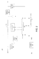
- FIG. 2 illustrates an embodiment of an SSPC for a DC power distribution system.
- FIG. 3 illustrates an embodiment of a bus-tie connected between two bus-tie SSPCs.
- a bus-tie between two EDPMs in a DC power distribution system may be connected between two bus-tie SSPCs, improving power quality on the HVDC buses during transfer of power between the HVDC buses.
- the bus-tie SSPCs may operate in a soft power mode during startup of power transfer across the bus-tie, preventing unwanted resonances that may occur with an electromechanical bus-tie breaker.
- FIG. 1 illustrates an embodiment of a DC power distribution system 100, which comprises a redundant dual EDPM system consistent with fault tolerant requirements appropriate for, for example, a modem aircraft electrical system.
- DC power distribution system 100 comprises EDPM units 110A-B, each comprising a respective HVDC bus 104A-B.
- the HVDC buses 104A-B are connected by bus tie 109 via a respective bus-tie SSPC 103A-B.
- Each EDPM 110A-B comprises a DC power source 101A-B (which may comprise a generator in some embodiments) connected to a source management SSPC 102A-B, which supplies power to a respective HVDC bus 104A-B, respectively.
- HVDC bus 104A powers electrical loads 107A-C via load management SSPCs 105A-C
- HVDC bus 104B powers electrical loads 107D-F via load management SSPCs 105D-F.
- Management computer 108 controls EDPM controllers 106A-B, which control the respective source management SSPCs 102A-B, load management SSPCs 105A-F, and bus-tie SSPCs 103A-B via respective data communication buses 111A-B.
- bus-tie 109 and bus-tie SSPCs 103A-B are inactive, and no power flows between EDPMs 110A-B.
- DC power source 101A powers HVDC bus 104A via source management SSPC 102A
- DC power source 101B powers HVDC bus 104B via source management SSPC 102B.
- management computer 108 detects a problem with one of DC power sources 101A-B, management computer 108 activates bus-tie SSPCs 103A-B for emergency mode power transfer across bus tie 109.
- Emergency mode may be activated when one of HVDC buses 104A-B is disconnected from its respective DC power source 101A-B, for example, during generator or generator feeder failure in one of power sources 101A-B.
- a set of protection algorithms may be used (including differential fault protection between buses, isolation of the faulty power source, and bus short condition) prior to closing the bus-tie SSPCs 103A-B.
- FIG. 2 illustrates an embodiment of an SSPC 200, which may comprise any of source management SSPCs 102A-B, bus-tie SSPCs 103A-B, or load management 105A-F of FIG. 1 .
- the SSPC 200 may be reconfigured via software that resides within SSPC controller 207 as a load management, source management, or bus-tie SSPC.
- the SSPC controller 207 may be implemented using a programmable microcontroller, gate array, and/or other configurable circuitry.
- SSPC 200 comprises a bidirectional switch 209.
- SSPC controller 207 controls the gate-source voltage (V GS ) and On/Off commands to power switch 209 via gate drive 208 based on information from input voltage sensor 202, output voltage sensor 211, output current sensor 210, temperature sensor 206, and data communications bus 213.
- Data communications bus 213 receives commands from management computer 108 of FIG. 1 via the SSPC's respective EDPM controller 106A-B and data communication bus 111A-B, and sends the received commands to SSPC controller 207.
- the internal modules and sensors comprising SSPC 200 are powered by DC control power input 203 via internal power supply 204 and internal power supply output 205.
- SSPC 200 comprises a bus-tie SSPC such as SSPCs 103A-B
- power may flow across SSPC 200 from connection 201 to connection 212 through switch 209, or in the opposite direction from connection 212 to connection 201 through switch 209. The direction is determined by whether power needs to be transferred from EDPM unit 110A to EDPM unit 110B, or from EDPM unit 110B to EDPM unit 110A.
- SSPC 200 may receive power at connection 201 from bus-tie 109 of FIG. 1 , and transfer the input power to the HVDC bus 104A-B located in the SSPC's respective EDPM via power switch 209 and connection 212.
- the power switch 209 may comprise one or more field effect transistors (FETs) in some embodiments; the number, type, and arrangement of the FETs may vary based on the type of SSPC.
- Power switch 209 may comprise a set of parallel silicon carbide (SiC) junction gate FETs (JFETs) in some embodiments.
- FIG. 3 illustrates an embodiment of bus-tie 109 connected between bus-tie SSPCs 103A-B.
- bus-tie SSPCs 103A-B comprise a power switch 209 controlled by an SSPC controller 207 via a gate drive 208.
- SSPC connection 301 of SSPC 103A is connected to HVDC bus 104A
- SSPC connection 302 of SSPC 103B is connected to HVDC bus 104B.
- Switches 209 in SSPCs 103A-B each comprise a respective FET 304A-B connected across a protective diode 303A-B.
- the protective diode 303A-B may be a Schottky diode with a low forward voltage drop and fast switching time.
- FETs 304A-B may comprise SiC JFETs in some embodiments.
- Power flow across bus-tie 109 is bidirectional; power may flow from SSPC 103A to SSPC 103B, or in the opposite direction from SSPC 103B to SSPC 103A, as needed.
- Use of two SSPCs 103A-B, each comprising a respective power switch 209, at either end of bus-tie 109 enables bidirectional power flow across bus-tie 109 between EDPMs 110A-B.
- the power flow across bus-tie 109 may also be interrupted bidirectionally by disconnecting both switches 209 in SSPCs 103A-B. This configuration allows size, weight, cost, and insertion loss reduction in the solid state bus-tie circuit breaker.
- the power switch 209 located in one or both of bus-tie SSPCs 103A-B are controlled by ramping up the V GS of the power switch 209 from negative bias (turn-off condition) to full on-voltage and minimum resistance (turn-on condition) within about one millisecond.
- Full on-voltage may comprise positive 3 volts DC in some embodiments. This allows the bus-tie SSPCs 103A-D to operate in a soft power transfer mode, resulting in significant reduction of system resonances in HVDC buses 104A-B.
- the technical effects and benefits of exemplary embodiments include simplification of SSPC construction by using only one power switch per SSPC, insertion loss reduction, and reduction of system resonances during power transfer between EPDM units.
Landscapes
- Engineering & Computer Science (AREA)
- Power Engineering (AREA)
- Direct Current Feeding And Distribution (AREA)
- Supply And Distribution Of Alternating Current (AREA)
- Remote Monitoring And Control Of Power-Distribution Networks (AREA)
Abstract
Description
- The subject matter disclosed herein relates generally to the field of solid state power controllers.
- Solid State Power Controllers (SSPCs) are used in power distribution systems in, for example, the aerospace industry, as an alternative to traditional electromechanical circuit breakers. An SSPC may distribute power to and protect various electrical loads. In comparison to electromechanical devices, SSPCs provide relatively fast response time, and may eliminate arcing during turn-off transient and bouncing during turn-on transient. SSPCs also do not suffer severe degradation during repeated fault isolation in comparison with electromechanical devices. SSPCs may be relatively small in weight and size. SSPCs facilitate advanced protection and diagnostics, allowing for efficient power distribution architectures and packaging techniques.
- A power distribution system comprising multiple electrical distribution and power management (EDPM) units may comprise a bus-tie connecting two high voltage DC (HVDC) buses located in different EDPM units. The bus-tie is activated during emergency mode, allowing one of the HVDC buses to power the other via the bus-tie in case of, for example, a power source failure. An electromechanical breaker may be used to open or close the bus-tie at the startup and end of emergency mode; however, the electromechanical breaker may induce unwanted resonance in the HVDC buses at startup of emergency mode.
- According to one aspect of the invention, a direct current (DC) power distribution system includes a first electrical distribution and power management (EDPM) unit comprising a first DC power source, the first DC power source being connected to a first high voltage DC bus connected to a first DC load, and a first bus-tie solid state power controller (SSPC), the first bus-tie SSPC being connected to the first HVDC bus; a second EDPM unit comprising a second DC power source, the second DC power source being connected to a second high voltage DC bus connected to a second DC load, and a second bus-tie SSPC, the second bus-tie SSPC being connected to the second HVDC bus; and a bus-tie connected between the first bus-tie SSPC and the second bus-tie SSPC, wherein in the event a power source failure occurs in the first EDPM unit, power flows from the second DC power source to the first HVDC bus via the second bus-tie SSPC, the bus-tie, and the first bus-tie SSPC.
- Other aspects, features, and techniques of the invention will become more apparent from the following description taken in conjunction with the drawings.
- Referring now to the drawings wherein like elements are numbered alike in the several FIGURES:
-
FIG. 1 illustrates an embodiment of a DC power distribution system comprising bus-tie SSPCs. -
FIG. 2 illustrates an embodiment of an SSPC for a DC power distribution system. -
FIG. 3 illustrates an embodiment of a bus-tie connected between two bus-tie SSPCs. - Embodiments of systems and methods for bus-tie SSPCs for a DC power distribution system are provided, with exemplary embodiments being discussed below in detail. A bus-tie between two EDPMs in a DC power distribution system may be connected between two bus-tie SSPCs, improving power quality on the HVDC buses during transfer of power between the HVDC buses. The bus-tie SSPCs may operate in a soft power mode during startup of power transfer across the bus-tie, preventing unwanted resonances that may occur with an electromechanical bus-tie breaker.
-
FIG. 1 illustrates an embodiment of a DCpower distribution system 100, which comprises a redundant dual EDPM system consistent with fault tolerant requirements appropriate for, for example, a modem aircraft electrical system. DCpower distribution system 100 comprisesEDPM units 110A-B, each comprising a respective HVDC bus 104A-B. The HVDC buses 104A-B are connected bybus tie 109 via a respective bus-tie SSPC 103A-B. Each EDPM 110A-B comprises aDC power source 101A-B (which may comprise a generator in some embodiments) connected to a source management SSPC 102A-B, which supplies power to a respective HVDC bus 104A-B, respectively. HVDC bus 104A powerselectrical loads 107A-C viaload management SSPCs 105A-C, and HVDC bus 104B powerselectrical loads 107D-F viaload management SSPCs 105D-F.Management computer 108 controlsEDPM controllers 106A-B, which control the respectivesource management SSPCs 102A-B,load management SSPCs 105A-F, and bus-tie SSPCs 103A-B via respectivedata communication buses 111A-B. - In normal operation, the bus-
tie 109 and bus-tie SSPCs 103A-B are inactive, and no power flows between EDPMs 110A-B.DC power source 101A powers HVDC bus 104A via source management SSPC 102A, andDC power source 101B powers HVDC bus 104B via source management SSPC 102B. When themanagement computer 108 detects a problem with one ofDC power sources 101A-B,management computer 108 activates bus-tie SSPCs 103A-B for emergency mode power transfer acrossbus tie 109. Emergency mode may be activated when one of HVDC buses 104A-B is disconnected from its respectiveDC power source 101A-B, for example, during generator or generator feeder failure in one ofpower sources 101A-B. Power flows across bus-tie 109 from the HVDC bus connected to the good power source to the HVDC bus connected to the bad power source, allowing the electrical loads associated with the EDPM having the bad power source to be powered by the good power source. To ensure safe power handling and transfer across bus-tie 109, a set of protection algorithms may be used (including differential fault protection between buses, isolation of the faulty power source, and bus short condition) prior to closing the bus-tie SSPCs 103A-B. -
FIG. 2 illustrates an embodiment of an SSPC 200, which may comprise any ofsource management SSPCs 102A-B, bus-tie SSPCs 103A-B, orload management 105A-F ofFIG. 1 . The SSPC 200 may be reconfigured via software that resides within SSPCcontroller 207 as a load management, source management, or bus-tie SSPC. For example, the SSPCcontroller 207 may be implemented using a programmable microcontroller, gate array, and/or other configurable circuitry. SSPC 200 comprises abidirectional switch 209.SSPC controller 207 controls the gate-source voltage (VGS) and On/Off commands topower switch 209 viagate drive 208 based on information frominput voltage sensor 202, output voltage sensor 211, outputcurrent sensor 210,temperature sensor 206, anddata communications bus 213.Data communications bus 213 receives commands frommanagement computer 108 ofFIG. 1 via the SSPC'srespective EDPM controller 106A-B anddata communication bus 111A-B, and sends the received commands toSSPC controller 207. The internal modules and sensors comprising SSPC 200 are powered by DCcontrol power input 203 viainternal power supply 204 and internalpower supply output 205. - In embodiments in which SSPC 200 comprises a bus-tie SSPC such as SSPCs 103A-B, power may flow across SSPC 200 from
connection 201 toconnection 212 throughswitch 209, or in the opposite direction fromconnection 212 toconnection 201 throughswitch 209. The direction is determined by whether power needs to be transferred fromEDPM unit 110A toEDPM unit 110B, or fromEDPM unit 110B toEDPM unit 110A. SSPC 200 may receive power atconnection 201 from bus-tie 109 ofFIG. 1 , and transfer the input power to the HVDC bus 104A-B located in the SSPC's respective EDPM viapower switch 209 andconnection 212. Thepower switch 209 may comprise one or more field effect transistors (FETs) in some embodiments; the number, type, and arrangement of the FETs may vary based on the type ofSSPC. Power switch 209 may comprise a set of parallel silicon carbide (SiC) junction gate FETs (JFETs) in some embodiments. -
FIG. 3 illustrates an embodiment of bus-tie 109 connected between bus-tie SSPCs 103A-B. Each of bus-tie SSPCs 103A-B comprise apower switch 209 controlled by an SSPCcontroller 207 via agate drive 208.SSPC connection 301 of SSPC 103A is connected to HVDC bus 104A, and SSPCconnection 302 of SSPC 103B is connected to HVDC bus 104B.Switches 209 inSSPCs 103A-B each comprise arespective FET 304A-B connected across aprotective diode 303A-B. Theprotective diode 303A-B may be a Schottky diode with a low forward voltage drop and fast switching time.FETs 304A-B may comprise SiC JFETs in some embodiments. Power flow across bus-tie 109 is bidirectional; power may flow from SSPC 103A to SSPC 103B, or in the opposite direction from SSPC 103B to SSPC 103A, as needed. Use of twoSSPCs 103A-B, each comprising arespective power switch 209, at either end of bus-tie 109 enables bidirectional power flow across bus-tie 109 betweenEDPMs 110A-B. The power flow across bus-tie 109 may also be interrupted bidirectionally by disconnecting bothswitches 209 inSSPCs 103A-B. This configuration allows size, weight, cost, and insertion loss reduction in the solid state bus-tie circuit breaker. - During emergency mode and transfer of power between HVDC buses 104A-B, the
power switch 209 located in one or both of bus-tie SSPCs 103A-B are controlled by ramping up the VGS of thepower switch 209 from negative bias (turn-off condition) to full on-voltage and minimum resistance (turn-on condition) within about one millisecond. Full on-voltage may comprise positive 3 volts DC in some embodiments. This allows the bus-tie SSPCs 103A-D to operate in a soft power transfer mode, resulting in significant reduction of system resonances in HVDC buses 104A-B. - The technical effects and benefits of exemplary embodiments include simplification of SSPC construction by using only one power switch per SSPC, insertion loss reduction, and reduction of system resonances during power transfer between EPDM units.
- The terminology used herein is for the purpose of describing particular embodiments only and is not intended to be limiting of the invention. While the description of the present invention has been presented for purposes of illustration and description, it is not intended to be exhaustive or limited to the invention in the form disclosed. Many modifications, variations, alterations, substitutions, or equivalent arrangements not hereto described will be apparent to those of ordinary skill in the art without departing from the scope of the invention. Additionally, while various embodiments of the invention have been described, it is to be understood that aspects of the invention may include only some of the described embodiments. Accordingly, the invention is not to be seen as limited by the foregoing description, but is only limited by the scope of the appended claims.
Claims (11)
- A direct current (DC) power distribution system (100), comprising:a first electrical distribution and power management (EDPM) unit (110A) comprising a first DC power source (101A), the first DC power source (101A) being connected to a first high voltage DC bus (104A) connected to a first DC load (107A-C), and a first bus-tie solid state power controller (SSPC) (103A), the first bus-tie SSPC (103A) being connected to the first HVDC bus (104A);a second EDPM unit (110B) comprising a second DC power source (101B), the second DC power source (101B) being connected to a second high voltage DC bus (104B) connected to a second DC load (107D-F), and a second bus-tie SSPC (103B), the second bus-tie SSPC (103B) being connected to the second HVDC bus (104B); anda bus-tie (109) connected between the first bus-tie SSPC (103A) and the second bus-tie SSPC (103B), wherein in the event a power source failure occurs in the first EDPM unit (110A), power flows from the second DC power (101B) source to the first HVDC bus (104A) via the second bus-tie SSPC (103B), the bus-tie (109), and the first bus-tie SSPC (103A).
- The DC power distribution system (100) of claim 1, wherein in the event a power source failure occurs in the second EDPM unit (110B), power flows from the first DC power source (101A) to the second HVDC(104B) bus via the first bus-tie SSPC (103A), the bus-tie (109), and the second bus-tie SSPC (103B).
- The DC power distribution system (100) of claim 1 or 2, wherein the first and second bus-tie SSPCs (103A-B) each comprise a power switch, each power switch comprising a field effect transistor (FET) connected across a Schottky diode.
- The DC power distribution system (100) of claim 3, wherein the FET comprises a silicon carbide (SiC) junction gate FET.
- The DC power distribution system (100) of claim 1, 2, 3 or 4, wherein the first and second bus-tie SSPCs (103A-B) are configured to enter an emergency mode comprising a soft power transfer in the event of a power source failure.
- The DC power distribution system (100) of claim 5, wherein the first and second bus-tie SSPCs (103A-B) each comprise a power switch, and wherein the soft power transfer comprises ramping each power switch from turn-off to turn-on within a time period of about 1 millisecond.
- The DC power distribution system (100) of claim 6, further arranged to turn off the power switches in the first and second bus-tie SSPCs (103A-B) after emergency mode is complete.
- The DC power distribution system (100) of any preceding claim, further comprising a first source management SSPC (102A) located between the first DC power source (101A) and the first HVDC bus (104A), and a second source management SSPC (102B) located between the second DC power source (101B) and the second HVDC bus (104B).
- The DC power distribution system (100) of any preceding claim, further comprising a first load management SSPC (105A) located between the first HVDC bus (104A) and the first DC load (107A), and a second load management SSPC (105D) located between the second HVDC bus (104B) and the second DC load (107D).
- The DC power distribution system (100) of any preceding claim, further comprising a management computer (108), the management computer (108) being configured to control a first controller (106A) located in the first EDPM (110A) and a second controller (106B) located in the second EDPM (110B).
- The DC power distribution system (100) of claim 10, wherein the first controller (106A) is configured to control a power switch located in the first bus-tie SSPC (103A) via an SSPC controller located in the first bus-tie SSPC (103A), and the second controller (106B) is configured to control a power switch located in the second bus-tie SSPC (103B) via an SSPC controller located in the second bus-tie SSPC (103B).
Applications Claiming Priority (1)
| Application Number | Priority Date | Filing Date | Title |
|---|---|---|---|
| US12/783,092 US8344544B2 (en) | 2010-05-19 | 2010-05-19 | Bus-tie SSPCS for DC power distribution system |
Publications (3)
| Publication Number | Publication Date |
|---|---|
| EP2388881A2 true EP2388881A2 (en) | 2011-11-23 |
| EP2388881A3 EP2388881A3 (en) | 2014-06-11 |
| EP2388881B1 EP2388881B1 (en) | 2018-02-28 |
Family
ID=44455265
Family Applications (1)
| Application Number | Title | Priority Date | Filing Date |
|---|---|---|---|
| EP11164217.9A Not-in-force EP2388881B1 (en) | 2010-05-19 | 2011-04-28 | Bus-tie SSPCs for d.c. power distribution system |
Country Status (2)
| Country | Link |
|---|---|
| US (1) | US8344544B2 (en) |
| EP (1) | EP2388881B1 (en) |
Cited By (6)
| Publication number | Priority date | Publication date | Assignee | Title |
|---|---|---|---|---|
| CN104319759A (en) * | 2014-09-03 | 2015-01-28 | 许昌许继晶锐科技有限公司 | DC power supply system for high-voltage DC transmission cooling system |
| EP2852020A1 (en) * | 2013-09-19 | 2015-03-25 | Airbus Operations GmbH | Power distribution architecture and aircraft comprising power distribution architecture |
| WO2015050555A1 (en) * | 2013-10-04 | 2015-04-09 | Ge Aviation Systems Llc | Dc power distribution system for an aircraft |
| CN105874684A (en) * | 2013-12-30 | 2016-08-17 | (株)晓星 | Power duplication apparatus for HVDC system and control method therefor |
| EP3101750A1 (en) * | 2015-05-13 | 2016-12-07 | Hamilton Sundstrand Corporation | High power solid state switches for aircraft |
| EP3267583A1 (en) * | 2016-07-07 | 2018-01-10 | Commissariat à l'Energie Atomique et aux Energies Alternatives | Circuit for selecting a supply voltage with controlled transition |
Families Citing this family (32)
| Publication number | Priority date | Publication date | Assignee | Title |
|---|---|---|---|---|
| US20130154351A1 (en) * | 2011-12-19 | 2013-06-20 | Mark J. Seger | Electrical architecture with power optimization |
| CN103158641B (en) * | 2011-12-19 | 2016-07-13 | 上海航空电器有限公司 | Intelligent distribution box |
| US9660435B2 (en) * | 2011-12-21 | 2017-05-23 | Sikorsky Aircraft Corporation | Multi-directional electrical power protection system |
| US8885306B2 (en) * | 2012-04-17 | 2014-11-11 | Hamilton Sundstrand Corporation | Power management and distribution system having a fault detection and isolation assembly and method |
| US9197056B2 (en) * | 2012-06-11 | 2015-11-24 | Honeywell International Inc. | Solid state power control system for aircraft high voltage DC power distribution |
| US9660446B2 (en) | 2013-10-04 | 2017-05-23 | Ge Aviation Systems Llc | Power distribution system for an aircraft |
| US9716385B2 (en) | 2014-06-16 | 2017-07-25 | Hamilton Sundstrand Corporation | Solid STTE power controller with parallel MOSFET load sharing |
| US9744925B2 (en) | 2014-07-31 | 2017-08-29 | General Electric Company | DC power system for marine applications |
| US9780643B2 (en) | 2014-09-22 | 2017-10-03 | General Electric Company | DC power system for marine applications |
| US9573539B2 (en) * | 2014-08-18 | 2017-02-21 | Hamilton Sundstrand Corporation | Electric system architecture for more-electric engine accessories |
| US9771164B2 (en) | 2014-10-27 | 2017-09-26 | Hamilton Sundstrand Corporation | Electric system architecture included in a more-electric engine (MEE) system |
| CN104578186B (en) * | 2014-12-25 | 2016-08-31 | 华中科技大学 | Contact device between a kind of net |
| US10090676B2 (en) | 2015-06-03 | 2018-10-02 | Northrop Grumman Systems Corporation | Aircraft DC power distribution systems and methods |
| EP3179591A1 (en) * | 2015-12-11 | 2017-06-14 | HS Elektronik Systeme GmbH | Solid state power controller |
| KR102467807B1 (en) * | 2017-01-13 | 2022-11-15 | 지멘스 에너지 에이에스 | DC power switching assembly and method |
| EP3349357A1 (en) * | 2017-01-13 | 2018-07-18 | Siemens Aktiengesellschaft | Power switching assembly and method |
| FR3068181B1 (en) * | 2017-06-27 | 2019-11-29 | Valeo Systemes De Controle Moteur | ELECTRICAL SYSTEM FOR DRIVING A FUNCTIONAL ORGAN AND A WHEEL DRIVE SYSTEM OF A MOTOR VEHICLE |
| CN108288853B (en) * | 2018-04-04 | 2024-05-28 | 中国商用飞机有限责任公司北京民用飞机技术研究中心 | Aircraft DC power supply system and power supply method |
| KR20200030819A (en) * | 2018-09-13 | 2020-03-23 | 엘에스산전 주식회사 | Module for supplying power and system for supplying power |
| GB201913016D0 (en) | 2019-09-10 | 2019-10-23 | Rolls Royce Plc | Elctrical systems |
| GB201913017D0 (en) | 2019-09-10 | 2019-10-23 | Rolls Royce Plc | Electrical system |
| GB201913015D0 (en) | 2019-09-10 | 2019-10-23 | Rolls Royce Plc | electrical systems |
| FR3132696B1 (en) * | 2022-02-14 | 2024-06-21 | Safran Electrical & Power | DC voltage electrical power distribution device, propulsion system and associated aircraft |
| KR20240070158A (en) | 2022-11-14 | 2024-05-21 | 현대자동차주식회사 | Power supply system of aircraft and controlling method thereof |
| FR3145657B1 (en) * | 2023-02-06 | 2025-02-07 | Safran Electrical & Power | Electrical distribution system for aircraft and associated method |
| KR20240150641A (en) * | 2023-04-06 | 2024-10-16 | 현대자동차주식회사 | Power supply system of aircraft and controlling method thereof |
| GB202314185D0 (en) * | 2023-09-18 | 2023-11-01 | Rolls Royce Deutschland Ltd & Co Kg | Dc power distribution and protection system |
| GB2635660A (en) * | 2023-11-10 | 2025-05-28 | Rolls Royce Deutschland Ltd & Co Kg | Power distribution system |
| JP2025131053A (en) * | 2024-02-28 | 2025-09-09 | 本田技研工業株式会社 | Power supply systems and mobile devices |
| JP2025152465A (en) * | 2024-03-28 | 2025-10-09 | 本田技研工業株式会社 | Power supply system, mobile body, and power supply system control method |
| US20260088614A1 (en) * | 2024-09-20 | 2026-03-26 | Leach International Corporation | Power distribution system and method of using the same |
| FR3167262A1 (en) * | 2024-10-03 | 2026-04-10 | Safran Electrical & Power | Aircraft electrical distribution system |
Family Cites Families (12)
| Publication number | Priority date | Publication date | Assignee | Title |
|---|---|---|---|---|
| US6246559B1 (en) | 1999-03-26 | 2001-06-12 | Honeywell International Inc | Power controller with short circuit protection |
| DE10030875C1 (en) * | 2000-06-23 | 2002-03-07 | Compact Dynamics Gmbh | The half-bridge |
| US6979863B2 (en) * | 2003-04-24 | 2005-12-27 | Cree, Inc. | Silicon carbide MOSFETs with integrated antiparallel junction barrier Schottky free wheeling diodes and methods of fabricating the same |
| US7439634B2 (en) * | 2004-08-24 | 2008-10-21 | Honeywell International Inc. | Electrical starting, generation, conversion and distribution system architecture for a more electric vehicle |
| US7400065B2 (en) | 2004-08-24 | 2008-07-15 | Honeywell International Inc. | Electrical power distribution system and method with active load control |
| US7453678B2 (en) | 2004-08-24 | 2008-11-18 | Hamilton Sunstrand Corporation | Power interruption system for electronic circuit breaker |
| US7656637B2 (en) * | 2004-10-12 | 2010-02-02 | The Boeing Company | Power control system pseudo power-up, aircraft including the power control system and method of controlling power in an aircraft |
| US7638897B2 (en) * | 2005-09-22 | 2009-12-29 | The General Electric Company | Method and system for powering a patient monitoring system |
| US7634329B2 (en) * | 2007-03-05 | 2009-12-15 | Honeywell International Inc. | Intelligent aircraft secondary power distribution system that facilitates condition based maintenance |
| US8148848B2 (en) * | 2008-01-24 | 2012-04-03 | Honeywell International, Inc. | Solid state power controller (SSPC) used as bus tie breaker in electrical power distribution systems |
| US7786620B2 (en) * | 2008-02-15 | 2010-08-31 | Honeywell International Inc. | Battery supplementing super capacitor energy storage charge and discharge converter |
| US8390151B2 (en) * | 2010-03-10 | 2013-03-05 | Hamilton Sundstrand Corporation | SSPC with active current limiting |
-
2010
- 2010-05-19 US US12/783,092 patent/US8344544B2/en not_active Expired - Fee Related
-
2011
- 2011-04-28 EP EP11164217.9A patent/EP2388881B1/en not_active Not-in-force
Non-Patent Citations (1)
| Title |
|---|
| None |
Cited By (14)
| Publication number | Priority date | Publication date | Assignee | Title |
|---|---|---|---|---|
| EP2852020A1 (en) * | 2013-09-19 | 2015-03-25 | Airbus Operations GmbH | Power distribution architecture and aircraft comprising power distribution architecture |
| JP2016539609A (en) * | 2013-10-04 | 2016-12-15 | ジーイー・アビエイション・システムズ・エルエルシー | Aircraft power distribution system |
| WO2015050555A1 (en) * | 2013-10-04 | 2015-04-09 | Ge Aviation Systems Llc | Dc power distribution system for an aircraft |
| CN105765816A (en) * | 2013-10-04 | 2016-07-13 | 通用电气航空系统有限责任公司 | Power distribution system for aircraft |
| CN105874684A (en) * | 2013-12-30 | 2016-08-17 | (株)晓星 | Power duplication apparatus for HVDC system and control method therefor |
| EP3091635A4 (en) * | 2013-12-30 | 2017-09-06 | Hyosung Corporation | Power duplication apparatus for hvdc system and control method therefor |
| US10038336B2 (en) | 2013-12-30 | 2018-07-31 | Hyosung Corporation | Power duplication apparatus for HVDC system and control method therefor |
| CN105874684B (en) * | 2013-12-30 | 2019-02-19 | 晓星重工业(株) | Power duplication device for HVDC system and control method thereof |
| CN104319759A (en) * | 2014-09-03 | 2015-01-28 | 许昌许继晶锐科技有限公司 | DC power supply system for high-voltage DC transmission cooling system |
| CN104319759B (en) * | 2014-09-03 | 2019-05-07 | 许昌许继晶锐科技有限公司 | A kind of DC power-supply system of voltage direct-current transmission valve cooling system |
| EP3101750A1 (en) * | 2015-05-13 | 2016-12-07 | Hamilton Sundstrand Corporation | High power solid state switches for aircraft |
| EP3267583A1 (en) * | 2016-07-07 | 2018-01-10 | Commissariat à l'Energie Atomique et aux Energies Alternatives | Circuit for selecting a supply voltage with controlled transition |
| FR3053857A1 (en) * | 2016-07-07 | 2018-01-12 | Commissariat A L'energie Atomique Et Aux Energies Alternatives | CONTROLLED TRANSITION POWER SUPPLY VOLTAGE SELECTION CIRCUIT |
| US10127953B2 (en) | 2016-07-07 | 2018-11-13 | Commissariat à l'énergie atomique et aux énergies alternatives | Circuit for selecting a power supply voltage having a controlled transition |
Also Published As
| Publication number | Publication date |
|---|---|
| EP2388881B1 (en) | 2018-02-28 |
| US8344544B2 (en) | 2013-01-01 |
| EP2388881A3 (en) | 2014-06-11 |
| US20110285202A1 (en) | 2011-11-24 |
Similar Documents
| Publication | Publication Date | Title |
|---|---|---|
| EP2388881B1 (en) | Bus-tie SSPCs for d.c. power distribution system | |
| US9197056B2 (en) | Solid state power control system for aircraft high voltage DC power distribution | |
| CN103731121B (en) | Fault-tolerant fail-safe connection equipment | |
| CN102668305B (en) | Battery energy storage system and method with short circuit protection | |
| CN104137372B (en) | There is the DC power system of systems protection capability | |
| EP1710890B1 (en) | Apparatus and methods for coordinated static switch operations for load transfers in uninterruptible power supply systems | |
| US20110260534A1 (en) | SSPC for AC Power Distribution | |
| CN109245083B (en) | Power system and method of operating a power system | |
| US9160174B2 (en) | Control architecture for power switching controller | |
| US20100103567A1 (en) | Circuit arrangement for protecting electronic devices against incorrect logic voltages | |
| CN109565275B (en) | Power distribution system and method | |
| EP3498607B1 (en) | Routable backup power control units | |
| WO2024027043A1 (en) | Power distribution system and method for flaying car, and flying car | |
| US9673692B2 (en) | Application of normally closed power semiconductor devices | |
| EP3672022B1 (en) | Controlled holdup discharge for improved component reliability | |
| CN102545182B (en) | Power controller system | |
| TW202335401A (en) | Persistent dc power and control switch | |
| EP2533424B1 (en) | Solid state contactor assembly | |
| CN206023172U (en) | It is suitable for the protection circuit and the system that powers using concatenation power supply of concatenation power-supply system | |
| US10770896B2 (en) | Solid state power controller | |
| WO2025239280A1 (en) | On-vehicle electric power distribution apparatus | |
| US20260088614A1 (en) | Power distribution system and method of using the same | |
| WO2025120576A1 (en) | Modular static transfer switch with wide-bandgap transistors | |
| WO2026018652A1 (en) | Vehicle control device |
Legal Events
| Date | Code | Title | Description |
|---|---|---|---|
| AK | Designated contracting states |
Kind code of ref document: A2 Designated state(s): AL AT BE BG CH CY CZ DE DK EE ES FI FR GB GR HR HU IE IS IT LI LT LU LV MC MK MT NL NO PL PT RO RS SE SI SK SM TR |
|
| AX | Request for extension of the european patent |
Extension state: BA ME |
|
| PUAI | Public reference made under article 153(3) epc to a published international application that has entered the european phase |
Free format text: ORIGINAL CODE: 0009012 |
|
| PUAL | Search report despatched |
Free format text: ORIGINAL CODE: 0009013 |
|
| AK | Designated contracting states |
Kind code of ref document: A3 Designated state(s): AL AT BE BG CH CY CZ DE DK EE ES FI FR GB GR HR HU IE IS IT LI LT LU LV MC MK MT NL NO PL PT RO RS SE SI SK SM TR |
|
| AX | Request for extension of the european patent |
Extension state: BA ME |
|
| RIC1 | Information provided on ipc code assigned before grant |
Ipc: H02J 9/04 20060101ALI20140507BHEP Ipc: H02J 1/10 20060101AFI20140507BHEP |
|
| 17P | Request for examination filed |
Effective date: 20141211 |
|
| RBV | Designated contracting states (corrected) |
Designated state(s): AL AT BE BG CH CY CZ DE DK EE ES FI FR GB GR HR HU IE IS IT LI LT LU LV MC MK MT NL NO PL PT RO RS SE SI SK SM TR |
|
| STAA | Information on the status of an ep patent application or granted ep patent |
Free format text: STATUS: EXAMINATION IS IN PROGRESS |
|
| 17Q | First examination report despatched |
Effective date: 20170309 |
|
| GRAP | Despatch of communication of intention to grant a patent |
Free format text: ORIGINAL CODE: EPIDOSNIGR1 |
|
| STAA | Information on the status of an ep patent application or granted ep patent |
Free format text: STATUS: GRANT OF PATENT IS INTENDED |
|
| INTG | Intention to grant announced |
Effective date: 20170907 |
|
| GRAS | Grant fee paid |
Free format text: ORIGINAL CODE: EPIDOSNIGR3 |
|
| GRAA | (expected) grant |
Free format text: ORIGINAL CODE: 0009210 |
|
| STAA | Information on the status of an ep patent application or granted ep patent |
Free format text: STATUS: THE PATENT HAS BEEN GRANTED |
|
| AK | Designated contracting states |
Kind code of ref document: B1 Designated state(s): AL AT BE BG CH CY CZ DE DK EE ES FI FR GB GR HR HU IE IS IT LI LT LU LV MC MK MT NL NO PL PT RO RS SE SI SK SM TR |
|
| REG | Reference to a national code |
Ref country code: GB Ref legal event code: FG4D Ref country code: CH Ref legal event code: EP |
|
| REG | Reference to a national code |
Ref country code: AT Ref legal event code: REF Ref document number: 975131 Country of ref document: AT Kind code of ref document: T Effective date: 20180315 |
|
| REG | Reference to a national code |
Ref country code: IE Ref legal event code: FG4D |
|
| REG | Reference to a national code |
Ref country code: DE Ref legal event code: R096 Ref document number: 602011045959 Country of ref document: DE Ref country code: FR Ref legal event code: PLFP Year of fee payment: 8 |
|
| REG | Reference to a national code |
Ref country code: NL Ref legal event code: MP Effective date: 20180228 |
|
| REG | Reference to a national code |
Ref country code: LT Ref legal event code: MG4D |
|
| REG | Reference to a national code |
Ref country code: AT Ref legal event code: MK05 Ref document number: 975131 Country of ref document: AT Kind code of ref document: T Effective date: 20180228 |
|
| PG25 | Lapsed in a contracting state [announced via postgrant information from national office to epo] |
Ref country code: ES Free format text: LAPSE BECAUSE OF FAILURE TO SUBMIT A TRANSLATION OF THE DESCRIPTION OR TO PAY THE FEE WITHIN THE PRESCRIBED TIME-LIMIT Effective date: 20180228 Ref country code: HR Free format text: LAPSE BECAUSE OF FAILURE TO SUBMIT A TRANSLATION OF THE DESCRIPTION OR TO PAY THE FEE WITHIN THE PRESCRIBED TIME-LIMIT Effective date: 20180228 Ref country code: NO Free format text: LAPSE BECAUSE OF FAILURE TO SUBMIT A TRANSLATION OF THE DESCRIPTION OR TO PAY THE FEE WITHIN THE PRESCRIBED TIME-LIMIT Effective date: 20180528 Ref country code: CY Free format text: LAPSE BECAUSE OF FAILURE TO SUBMIT A TRANSLATION OF THE DESCRIPTION OR TO PAY THE FEE WITHIN THE PRESCRIBED TIME-LIMIT Effective date: 20180228 Ref country code: LT Free format text: LAPSE BECAUSE OF FAILURE TO SUBMIT A TRANSLATION OF THE DESCRIPTION OR TO PAY THE FEE WITHIN THE PRESCRIBED TIME-LIMIT Effective date: 20180228 Ref country code: FI Free format text: LAPSE BECAUSE OF FAILURE TO SUBMIT A TRANSLATION OF THE DESCRIPTION OR TO PAY THE FEE WITHIN THE PRESCRIBED TIME-LIMIT Effective date: 20180228 Ref country code: NL Free format text: LAPSE BECAUSE OF FAILURE TO SUBMIT A TRANSLATION OF THE DESCRIPTION OR TO PAY THE FEE WITHIN THE PRESCRIBED TIME-LIMIT Effective date: 20180228 |
|
| PG25 | Lapsed in a contracting state [announced via postgrant information from national office to epo] |
Ref country code: LV Free format text: LAPSE BECAUSE OF FAILURE TO SUBMIT A TRANSLATION OF THE DESCRIPTION OR TO PAY THE FEE WITHIN THE PRESCRIBED TIME-LIMIT Effective date: 20180228 Ref country code: GR Free format text: LAPSE BECAUSE OF FAILURE TO SUBMIT A TRANSLATION OF THE DESCRIPTION OR TO PAY THE FEE WITHIN THE PRESCRIBED TIME-LIMIT Effective date: 20180529 Ref country code: RS Free format text: LAPSE BECAUSE OF FAILURE TO SUBMIT A TRANSLATION OF THE DESCRIPTION OR TO PAY THE FEE WITHIN THE PRESCRIBED TIME-LIMIT Effective date: 20180228 Ref country code: SE Free format text: LAPSE BECAUSE OF FAILURE TO SUBMIT A TRANSLATION OF THE DESCRIPTION OR TO PAY THE FEE WITHIN THE PRESCRIBED TIME-LIMIT Effective date: 20180228 Ref country code: BG Free format text: LAPSE BECAUSE OF FAILURE TO SUBMIT A TRANSLATION OF THE DESCRIPTION OR TO PAY THE FEE WITHIN THE PRESCRIBED TIME-LIMIT Effective date: 20180528 Ref country code: AT Free format text: LAPSE BECAUSE OF FAILURE TO SUBMIT A TRANSLATION OF THE DESCRIPTION OR TO PAY THE FEE WITHIN THE PRESCRIBED TIME-LIMIT Effective date: 20180228 |
|
| PG25 | Lapsed in a contracting state [announced via postgrant information from national office to epo] |
Ref country code: IT Free format text: LAPSE BECAUSE OF FAILURE TO SUBMIT A TRANSLATION OF THE DESCRIPTION OR TO PAY THE FEE WITHIN THE PRESCRIBED TIME-LIMIT Effective date: 20180228 Ref country code: AL Free format text: LAPSE BECAUSE OF FAILURE TO SUBMIT A TRANSLATION OF THE DESCRIPTION OR TO PAY THE FEE WITHIN THE PRESCRIBED TIME-LIMIT Effective date: 20180228 Ref country code: PL Free format text: LAPSE BECAUSE OF FAILURE TO SUBMIT A TRANSLATION OF THE DESCRIPTION OR TO PAY THE FEE WITHIN THE PRESCRIBED TIME-LIMIT Effective date: 20180228 Ref country code: EE Free format text: LAPSE BECAUSE OF FAILURE TO SUBMIT A TRANSLATION OF THE DESCRIPTION OR TO PAY THE FEE WITHIN THE PRESCRIBED TIME-LIMIT Effective date: 20180228 Ref country code: RO Free format text: LAPSE BECAUSE OF FAILURE TO SUBMIT A TRANSLATION OF THE DESCRIPTION OR TO PAY THE FEE WITHIN THE PRESCRIBED TIME-LIMIT Effective date: 20180228 |
|
| REG | Reference to a national code |
Ref country code: DE Ref legal event code: R119 Ref document number: 602011045959 Country of ref document: DE |
|
| PG25 | Lapsed in a contracting state [announced via postgrant information from national office to epo] |
Ref country code: DK Free format text: LAPSE BECAUSE OF FAILURE TO SUBMIT A TRANSLATION OF THE DESCRIPTION OR TO PAY THE FEE WITHIN THE PRESCRIBED TIME-LIMIT Effective date: 20180228 Ref country code: CZ Free format text: LAPSE BECAUSE OF FAILURE TO SUBMIT A TRANSLATION OF THE DESCRIPTION OR TO PAY THE FEE WITHIN THE PRESCRIBED TIME-LIMIT Effective date: 20180228 Ref country code: SK Free format text: LAPSE BECAUSE OF FAILURE TO SUBMIT A TRANSLATION OF THE DESCRIPTION OR TO PAY THE FEE WITHIN THE PRESCRIBED TIME-LIMIT Effective date: 20180228 Ref country code: SM Free format text: LAPSE BECAUSE OF FAILURE TO SUBMIT A TRANSLATION OF THE DESCRIPTION OR TO PAY THE FEE WITHIN THE PRESCRIBED TIME-LIMIT Effective date: 20180228 Ref country code: MC Free format text: LAPSE BECAUSE OF FAILURE TO SUBMIT A TRANSLATION OF THE DESCRIPTION OR TO PAY THE FEE WITHIN THE PRESCRIBED TIME-LIMIT Effective date: 20180228 |
|
| REG | Reference to a national code |
Ref country code: CH Ref legal event code: PL |
|
| REG | Reference to a national code |
Ref country code: BE Ref legal event code: MM Effective date: 20180430 |
|
| PLBE | No opposition filed within time limit |
Free format text: ORIGINAL CODE: 0009261 |
|
| STAA | Information on the status of an ep patent application or granted ep patent |
Free format text: STATUS: NO OPPOSITION FILED WITHIN TIME LIMIT |
|
| REG | Reference to a national code |
Ref country code: IE Ref legal event code: MM4A |
|
| PG25 | Lapsed in a contracting state [announced via postgrant information from national office to epo] |
Ref country code: DE Free format text: LAPSE BECAUSE OF NON-PAYMENT OF DUE FEES Effective date: 20181101 Ref country code: LU Free format text: LAPSE BECAUSE OF NON-PAYMENT OF DUE FEES Effective date: 20180428 |
|
| 26N | No opposition filed |
Effective date: 20181129 |
|
| PG25 | Lapsed in a contracting state [announced via postgrant information from national office to epo] |
Ref country code: BE Free format text: LAPSE BECAUSE OF NON-PAYMENT OF DUE FEES Effective date: 20180430 Ref country code: CH Free format text: LAPSE BECAUSE OF NON-PAYMENT OF DUE FEES Effective date: 20180430 Ref country code: LI Free format text: LAPSE BECAUSE OF NON-PAYMENT OF DUE FEES Effective date: 20180430 Ref country code: SI Free format text: LAPSE BECAUSE OF FAILURE TO SUBMIT A TRANSLATION OF THE DESCRIPTION OR TO PAY THE FEE WITHIN THE PRESCRIBED TIME-LIMIT Effective date: 20180228 |
|
| PG25 | Lapsed in a contracting state [announced via postgrant information from national office to epo] |
Ref country code: IE Free format text: LAPSE BECAUSE OF NON-PAYMENT OF DUE FEES Effective date: 20180428 |
|
| PG25 | Lapsed in a contracting state [announced via postgrant information from national office to epo] |
Ref country code: MT Free format text: LAPSE BECAUSE OF NON-PAYMENT OF DUE FEES Effective date: 20180428 |
|
| PG25 | Lapsed in a contracting state [announced via postgrant information from national office to epo] |
Ref country code: TR Free format text: LAPSE BECAUSE OF FAILURE TO SUBMIT A TRANSLATION OF THE DESCRIPTION OR TO PAY THE FEE WITHIN THE PRESCRIBED TIME-LIMIT Effective date: 20180228 |
|
| PG25 | Lapsed in a contracting state [announced via postgrant information from national office to epo] |
Ref country code: PT Free format text: LAPSE BECAUSE OF FAILURE TO SUBMIT A TRANSLATION OF THE DESCRIPTION OR TO PAY THE FEE WITHIN THE PRESCRIBED TIME-LIMIT Effective date: 20180228 Ref country code: HU Free format text: LAPSE BECAUSE OF FAILURE TO SUBMIT A TRANSLATION OF THE DESCRIPTION OR TO PAY THE FEE WITHIN THE PRESCRIBED TIME-LIMIT; INVALID AB INITIO Effective date: 20110428 |
|
| PG25 | Lapsed in a contracting state [announced via postgrant information from national office to epo] |
Ref country code: MK Free format text: LAPSE BECAUSE OF NON-PAYMENT OF DUE FEES Effective date: 20180228 |
|
| PG25 | Lapsed in a contracting state [announced via postgrant information from national office to epo] |
Ref country code: IS Free format text: LAPSE BECAUSE OF FAILURE TO SUBMIT A TRANSLATION OF THE DESCRIPTION OR TO PAY THE FEE WITHIN THE PRESCRIBED TIME-LIMIT Effective date: 20180628 |
|
| PGFP | Annual fee paid to national office [announced via postgrant information from national office to epo] |
Ref country code: FR Payment date: 20210323 Year of fee payment: 11 |
|
| PGFP | Annual fee paid to national office [announced via postgrant information from national office to epo] |
Ref country code: GB Payment date: 20210324 Year of fee payment: 11 |
|
| GBPC | Gb: european patent ceased through non-payment of renewal fee |
Effective date: 20220428 |
|
| PG25 | Lapsed in a contracting state [announced via postgrant information from national office to epo] |
Ref country code: GB Free format text: LAPSE BECAUSE OF NON-PAYMENT OF DUE FEES Effective date: 20220428 Ref country code: FR Free format text: LAPSE BECAUSE OF NON-PAYMENT OF DUE FEES Effective date: 20220430 |