EP2388759A2 - Methods and systems for a in-trail procedures display - Google Patents
Methods and systems for a in-trail procedures display Download PDFInfo
- Publication number
- EP2388759A2 EP2388759A2 EP11155504A EP11155504A EP2388759A2 EP 2388759 A2 EP2388759 A2 EP 2388759A2 EP 11155504 A EP11155504 A EP 11155504A EP 11155504 A EP11155504 A EP 11155504A EP 2388759 A2 EP2388759 A2 EP 2388759A2
- Authority
- EP
- European Patent Office
- Prior art keywords
- itp
- aircraft
- target
- host
- icons
- Prior art date
- Legal status (The legal status is an assumption and is not a legal conclusion. Google has not performed a legal analysis and makes no representation as to the accuracy of the status listed.)
- Granted
Links
- 238000000034 method Methods 0.000 title claims abstract description 31
- 230000000007 visual effect Effects 0.000 claims abstract description 6
- 230000000977 initiatory effect Effects 0.000 claims description 15
- 230000008859 change Effects 0.000 claims description 9
- 230000008569 process Effects 0.000 description 7
- 238000000926 separation method Methods 0.000 description 5
- 230000007704 transition Effects 0.000 description 4
- 230000009471 action Effects 0.000 description 3
- 230000005540 biological transmission Effects 0.000 description 3
- 230000004913 activation Effects 0.000 description 2
- 238000012508 change request Methods 0.000 description 2
- 230000001419 dependent effect Effects 0.000 description 2
- 238000001914 filtration Methods 0.000 description 2
- 230000008520 organization Effects 0.000 description 2
- 230000003213 activating effect Effects 0.000 description 1
- 230000008901 benefit Effects 0.000 description 1
- 230000000903 blocking effect Effects 0.000 description 1
- 239000003086 colorant Substances 0.000 description 1
- 238000010586 diagram Methods 0.000 description 1
- 230000002349 favourable effect Effects 0.000 description 1
- 230000010006 flight Effects 0.000 description 1
- 238000009472 formulation Methods 0.000 description 1
- 239000000203 mixture Substances 0.000 description 1
- 238000010079 rubber tapping Methods 0.000 description 1
- 239000007787 solid Substances 0.000 description 1
Images






Classifications
-
- G—PHYSICS
- G08—SIGNALLING
- G08G—TRAFFIC CONTROL SYSTEMS
- G08G5/00—Traffic control systems for aircraft
- G08G5/20—Arrangements for acquiring, generating, sharing or displaying traffic information
- G08G5/21—Arrangements for acquiring, generating, sharing or displaying traffic information located onboard the aircraft
-
- G—PHYSICS
- G08—SIGNALLING
- G08G—TRAFFIC CONTROL SYSTEMS
- G08G5/00—Traffic control systems for aircraft
- G08G5/20—Arrangements for acquiring, generating, sharing or displaying traffic information
- G08G5/25—Transmission of traffic-related information between aircraft
-
- G—PHYSICS
- G08—SIGNALLING
- G08G—TRAFFIC CONTROL SYSTEMS
- G08G5/00—Traffic control systems for aircraft
- G08G5/20—Arrangements for acquiring, generating, sharing or displaying traffic information
- G08G5/26—Transmission of traffic-related information between aircraft and ground stations
-
- G—PHYSICS
- G08—SIGNALLING
- G08G—TRAFFIC CONTROL SYSTEMS
- G08G5/00—Traffic control systems for aircraft
- G08G5/30—Flight plan management
- G08G5/34—Flight plan management for flight plan modification
-
- G—PHYSICS
- G08—SIGNALLING
- G08G—TRAFFIC CONTROL SYSTEMS
- G08G5/00—Traffic control systems for aircraft
- G08G5/50—Navigation or guidance aids
- G08G5/53—Navigation or guidance aids for cruising
-
- G—PHYSICS
- G08—SIGNALLING
- G08G—TRAFFIC CONTROL SYSTEMS
- G08G5/00—Traffic control systems for aircraft
- G08G5/50—Navigation or guidance aids
- G08G5/55—Navigation or guidance aids for a single aircraft
-
- G—PHYSICS
- G08—SIGNALLING
- G08G—TRAFFIC CONTROL SYSTEMS
- G08G5/00—Traffic control systems for aircraft
- G08G5/70—Arrangements for monitoring traffic-related situations or conditions
- G08G5/72—Arrangements for monitoring traffic-related situations or conditions for monitoring traffic
- G08G5/723—Arrangements for monitoring traffic-related situations or conditions for monitoring traffic from the aircraft
Definitions
- ADS-B Automatic dependent surveillance-broadcast
- ITP in-trail procedures
- ITP is airborne ADS-B enabled climbs and descents through otherwise blocked flight levels.
- ITP is based on an approved International Civil Aviation Organization (ICAO) procedure whereby a controller separates aircraft based on information derived from cockpit sources that is relayed manually by the flight crew.
- IAO International Civil Aviation Organization
- ITP allows a leading or following aircraft on the same track to climb or descend to a desired flight level through flight levels occupied by other aircraft.
- An ITP display enables a flight crew to determine if specific criteria for an ITP are met with respect to one or two reference aircraft at intervening flight levels. These criteria ensure that the spacing between the estimated positions of the ITP aircraft and reference aircraft always exceeds the ITP separation minimum of 10 NM, while vertical separation does not exist during the climb or descent. Once the flight crew has established that the ITP criteria are met, they request an ITP climb or descent, identifying any reference aircraft in the clearance request.
- Air Traffic Control ATC must determine if standard separation will be met for all aircraft at the requested flight level -- and at all flight levels between the initial flight level and requested flight level.
- a standard (non-ITP) flight level change clearance is likely to be granted. Otherwise, if the reference aircraft are the only blocking aircraft, the controller evaluates the ITP request. ATC determines if the reference aircraft have been cleared to change speed or change flight level, or are about to reach a point at which a significant change of track will occur. The controller also ensures that the requesting aircraft is not referenced in another procedure. ATC also ensures that the positive Mach difference with the reference aircraft is no greater than 0.06 Mach. If each of these criteria is satisfied, then ATC may issue the ITP flight level change clearance.
- FIGURES 1 and 2 An example of an ITP climb is shown in FIGURES 1 and 2 .
- An ITP aircraft is behind a reference aircraft that is at a higher intervening flight level (FL350).
- Standard air traffic control (ATC) procedures apply to the other aircraft (two aircraft at FL360 and one at FL350).
- the ITP system displays the information derived from received ADS-B data on traffic displays such as a cockpit display of traffic information (CDTI). Both plan-view and vertical situational awareness displays (VSAD) are possible, see FIGURE 3 . These displays require a large amount of pilot workload when preparing an ITP clearance request.
- traffic displays such as a cockpit display of traffic information (CDTI).
- CDTI traffic information
- VSAD vertical situational awareness displays
- the present invention provides systems and methods for improving situational awareness on an in-trail procedures display.
- the present invention provides a display with visual identification and indication for aircraft that do not meet the ITP criteria.
- feedback is provided when a pilot selects an invalid ITP flight level, unambiguous feedback is provided to the pilot upon selection of a valid flight level, and valid inter-target aircraft located in intervening flight levels after selection of a valid flight level are positively identified and invalid target aircraft for selection are uniquely identified.
- automatic selection of valid target aircraft and automatic generation of a clearance request text based on manually or automatically selected valid target aircraft and a desired flight level are available.
- FIGURES 1 and 2 illustrate side views of an aircraft performing altitude changes during oceanic flight operations
- FIGURE 3 illustrates an in-trail procedure (ITP) display formed in accordance with the prior art
- FIGURE 4 illustrates a schematic diagram of a system formed in accordance with an embodiment of the present invention
- FIGURE 5 illustrates sections of an ITP display formed in accordance with an embodiment of the present invention
- FIGURES 6 , 7 and 9-16 are screen shots of an exemplary ITP display formed in accordance with an embodiment of the present invention.
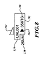
- FIGURE 8 illustrates a target icon with associated data.
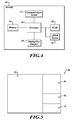
- FIGURE 4 illustrates an embodiment of a system on an aircraft 20 for providing improved in-trail procedures (ITP) functionality.
- the exemplary system includes a processor 24, automatic dependent surveillance-broadcast (ADS-B) system 26, a traffic collision avoidance system (TCAS) 28 (optional), a display device 30, a communications system 32, and memory 34.
- the processor 24 may be connected to other aircraft systems, such as a Global Positioning System (GPS) or comparable device, for retrieving various flight information (e.g., position information).
- GPS Global Positioning System
- a transponder is connected to the TCAS and the ADS-B device is integrated within the TCAS unit.
- the processor 24 receives target information of other aircraft in the vicinity of the aircraft 20 via the ADS-B system 26 and, if included, the TCAS 28.
- a TCAS unit includes the ADS-B functionality and this processor 24 is included in the TCAS unit.
- the processor 24 presents the received target information on the display device 30. Pilots interact with the display device 30 using a user interface, such as a cursor control device or a touch screen display, for analyzing and sending an ITP change of altitude request to a controller authority via the communications system 32. This will be shown in more detail below and in the following figures.
- FIGURE 5 illustrates an exemplary display 50 that is segmented into various sections for presenting useful information for the pilots.
- the sections of the display 50 include a main display section 52, an ITP guidance section 54, a traffic status section 56, and an ITP advisory message section 58.
- the main display section 52 allows a pilot to switch between a plan view and an ITP view.
- the ITP view is comparable to a vertical profile display except that the relative distances of the displayed traffic (i.e. icons) are ITP distances.
- the ITP distance is the distance between the host aircraft and the target aircraft as defined by the difference in distance to an aircraft calculated common point along a projection of each aircraft's track in front of or behind the aircraft as appropriate.
- the ITP guidance section 54 presents the pilot with all the steps necessary for executing an ITP request. This will be described in more detail below.
- the traffic status section 56 provides various information about traffic targets that are selected by the pilot or automatically selected by the processor 24 in the main display section 52. This will be shown in more detail by example in the following figures.
- the ITP advisory message section 58 provides pilots information relating to selections they made within the main display section 52 if the action that the pilot is performing is unavailable or invalid.
- the sections 52-58 may be distributed on the display in a different manner.
- FIGURE 6 illustrates a display 80 that is presently in plan view display mode.
- the display 80 is a touch screen display that allows a user to select from various menu items, buttons, icons, etc. for presenting related information.
- a cursor control device such as a mouse may be used for selecting displayed linked items.
- a main section 84 of the display 80 presents a plan view with a host aircraft icon 88 shown in the center of one or more radius rings 90.
- a selectable indicator shows the present view mode. The user can alter what is displayed in the main section 84 by activating an arrow icon (menu selection button) that is adjacent to the view mode indicators/selector.
- a column of user selectable display attributes may be set by the user.
- the display attributes include (but are not limited to): flight identification information (ID), altitude view mode, altitude filter and lateral filter settings.
- ID flight identification information
- altitude view mode altitude filter
- lateral filter settings e.g., a column of user selectable display attributes.
- the display allows users to filter visible traffic by setting the visible altitude band above and below the aircraft (by means of an altitude filter).
- conventional TCAS altituide filters NVMAL, ABOVE, BELOW
- 15 NM Lateral Filter allows the pilot to declutter the ITP View (the traffic filtering is not performed on the Plan View Display - but 15 NM reference lines are depicted once the Lateral Filter is engaged).
- Both relative and absolute altitude display modes can be selected by using the ALT VIEW MODE menu slections.
- the Flight ID menu item allows the user to select display of the traffic ID for all traffic being displayed on the Plan View display. Altitude filtering is described in corresponding U.S. Patent Application No. 12/774,513 filed May 5, 2010 , which is hereby incorporated by reference.
- the processor 24 generates icons to be displayed in the plan-view display relative to the host aircraft icon 88 based on TCAS or ADS-B information received from an associated target aircraft.
- traffic targets from other data sources such as TIS-B (Traffic Information Services - Broadcast) could also be processed and displayed.
- Target aircraft that are outside of the defaulted or user selected altitude and lateral filter settings are not displayed as icons in the main section 84 of the plan view or the ITP view.
- the altitude filters for plan view and ITP view may be independent in some embodiments (i.e., user selects different altitude filter values for the two views).
- a first target icon 96 is associated with a TCAS target aircraft and a second target icon 98 is associated with an ADS-B target aircraft.
- Each of these target icons 96, 98 include a relative altitude value that is a value of altitude relative to the host aircraft.
- the ADS-B icons also present flight ID information if that display feature is selected.
- Also displayed within the main section 84 is an altitude view mode enunciator 102, values associated with an altitude filter 104, and lateral filter lines 106 with an associated lateral filter distance value.
- the altitude view mode enunciator 102 provides visual feedback to the user of the active altitude filter selection. It also indicates whether the user selected relative or absolute altitude.
- the lateral filter lines 106 indicate the extent of lateral filter selected. Only traffic between these lines is shown in the ITP view (i.e., the traffic is not filtered from the plan view).
- a status section 112 provides various information about target icons that are selected (e.g., user's finger touching target icon on touch screen) within the main section 84.
- the status information includes, but is not limited to, flight ID, altitude, range, ITP distance and ground speed differential.
- An ITP advisory message section 118 presents information when a user action is unavailable or invalid.
- Transition to the ITP view can occur by either selecting the ITP view text located in a view mode section 86 of the main section 84 or by activation of a Formulate ITP clearance (CLNC) button 114 located in an ITP procedural guidance section 116. Selection of either one of those transitions the display to ITP view 120 shown in FIGURE 7 .
- the main section 84 presents a vertical profile view showing flight levels on a vertical axis. Each flight level includes a corresponding line. ITP distance is presented on a horizontal axis with a host aircraft icon 126 located on a center flight level and at zero on the ITP distance scale. This vertical profile display or ITP view 120 shows all target aircraft that are above or below the host aircraft.
- the target aircraft icons are associated with aircraft that fall within the altitude band.
- the altitude band is shown in the upper right corner of the main section 84.
- the altitude filter is plus and minus 4000 feet. If a lateral filter selection was made then a read-out that indicates the current lateral filter would be displayed. In this example, a lateral filter of 20 NM is displayed in the bottom right corner of the main section 84.
- the associated icons with the aircraft symbol 122 include traffic tag data (see FIGURE 8 ).
- the traffic tag data includes flight ID 124, ITP distance 128, and/or speed differential relative to the host aircraft 130.
- ITP distance information may be optionally or additionally shown by an ITP distance scale located at the bottom of the main section 84.
- a groundspeed differential arrow 134 is included with the traffic tag data. The groundspeed differential arrow 134 provides information on whether other traffic is converging or separating from ownship. When the groundspeed differential arrow 134 points to the right, it indicates that the traffic is faster than ownship, and the converse is true.
- a solid groundspeed differential arrow 134 indicates that the traffic is converging on ownship, whereas a hollow groundspeed differential arrow 134 indicates that the traffic is separating from ownship.
- a dotted box surrounds or some other indicator distinguishes an aircraft icon when the user selects that icon. Selection of the aircraft icon presents status information for that target aircraft in the traffic status section 112, see the dotted box around the icon AF320 in FIGURE 6 . Selection can be performed by touching or tapping the desired icon with a finger or pointing device.
- the current flight level of the host aircraft is uniquely identified from all the other flight level lines. In this embodiment, the current flight level for the host aircraft is indicated in magenta. It can be appreciated that other colors or graphical representations may be used.
- Target aircraft icon that do not satisfy ITP minimum criteria are highlighted in a distinct color, e.g. blue.
- only the failing ITP criteria of the traffic tag data are highlighted in a distinct color (i.e. not the aircraft symbol).
- the user has selected icon QH3 which was visually identified to not satisfy ITP minimum criteria.
- the advisory message section 118 indicates why the aircraft associated with icon QH3 does not meet the ITP minimum criteria.
- Icon QH3 does not meet the ITP criteria because the ITP distance is less than 15 nautical miles.
- FIGURE 10 illustrates a display 150 after the user has selected the Formulate ITP CLNC button 114 while in the ITP view mode and after the user has selected flight level (FL) 310 for attaining an ITP clearance. Because the user selected a flight level that is only a 1000 feet above the current flight level of the host aircraft, the line associated with flight level 310 and a caret located at a left end of the line associated with the selected flight level are presented in grey. An advisory message is presented in the advisory message section 118 because the processor 24 determined that because the selected flight level is only 1000 feet above the flight level of the host aircraft, an ITP clearance request is not needed.
- a selected desired flight level (FL) box 154 is displayed above a Cancel button 156, a Prev(ious) view button 158, and a Next view button 160. Selection of the Prev(ious) view and Next view buttons 158, 160 are comparable to forward and back browser window transition buttons.
- the Cancel button 156 allows the user to cancel a current ITP request formulation. Because the selected FL 310 is not valid or does not require an ITP request, the selected flight level value is not inserted into the desired FL box 154. In an alternative embodiment, the (incorrect) selected flight level value is entered in grey (i.e., a color different than if the selected flight level value was valid) in the desired FL box 154.
- the user has selected FL 330 as the desired flight level for an ITP climb.
- the processor 24 determines that the selected FL 330 is valid and then unambiguously indicates the validity of FL 330.
- a caret is presented on the left side of a line associated with FL 330 and both the line and the caret are presented in green. Because the selected FL 330 is valid, it is automatically entered into the selected desired FL box 154. The user then selects the Next view button 160 for continuing the ITP request process.
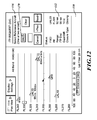
- FIGURE 12 shows step 2 of the ITP request process.
- a user is requested to manually select one or two reference aircraft that are located between the host aircraft's current flight level and the selected flight level.
- the user selects aircraft UAL23 as the first aircraft.
- the flight ID information for the selected aircraft is automatically populated into a reference aircraft window 170 located in the ITP clearance section 116.
- status information for the selected aircraft UAL23 is automatically inserted into the status section 112.
- Valid reference aircraft selections are highlighted by use of color (e.g., green) in the window 170. Because the selected aircraft UAL23 is a valid reference aircraft according to an ITP clearance request, no advisory messages are presented in the advisory message section 118.
- the valid reference flight ID in the traffic status area could also be highlighed by a color change, e.g. green.
- the valid aircraft icons i.e., meeting ITP initiation criteria such as groundspeed differential, ITP distance and relative altitude located between the selected flight level and the current flight level of the host aircraft are identified in white.
- the ITP procedure requires reference aircraft to be within two flight levels of the ownship current flight level (i.e., the relative altitude criteria). Aircraft that are more than two flight levels away are colored in grey in this step of the process.
- the processor 24 determines which aircraft within the intervening flight levels are valid (ADS-B equipment, ITP distance, ground speed differential, relative altitude criteria). In another embodiment, the processor 24 automatically selects valid reference aircraft located within the intervening flight levels and populates the window 170 accordingly. If only one or two valid reference aircraft exist within the intervening flight levels, all are automatically selected. If more than two valid aircraft exist within the intervening flight levels, the processor 24 selects the two aircraft that are the closest to the host aircraft. Once an aircraft icon has been manually or automatically selected, it is indicated in green in the ITP view. A user or pilot can override any automatic selection made by the processor 24.
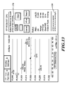
- FIGURE 13 illustrates when a user selects an aircraft AF320 that is outside of the intervening flight levels. In this situation, the selected aircraft AF320 is not inserted into the selected reference aircraft window 170 and the advisory message section 118 indicates why this is an invalid selection.
- the processor 24 After manual or automatic selection of reference aircraft and activation of the Next view button 160, the process continues on to the third step of the ITP request process as shown in FIGURE 14 .
- the processor 24 generates and displays ITP clearance request text based on the selected valid reference aircraft and the selected valid flight level.
- the ITP clearance request text is displayed within the ITP guidance section 116.
- the format of the clearance request text is consistent with recent International Civil Aviation Organization (ICAO) standards.
- the ITP clearance request text includes an altitude value, in this example FL 330 and free text which is formatted accordingly.
- the pilot either manually enters the clearance text into a data link interface (e.g. communications system 32) or the processor 24 uploads the clearance request text automatically and transmits it to the ATC via the communications system 32.
- a data link interface e.g. communications system 32
- the processor 24 uploads the clearance request text automatically and transmits it to the ATC via the communications system 32.
- a Controller Pilot Data Link Communications (CPDLC) application is included for sending requests to and receive clearances from ATC.
- the CPDLC is typically hosted in a Multi-Function Display (MFD) or a Flight Management System (FMS) Control Display Unit (CDU).
- MFD Multi-Function Display
- FMS Flight Management System
- CDU Control Display Unit
- Manual ITP flight level change requests are made via data link in a manner similar to a standard flight level change request, but with additional ITP-specific information entered in the free text fields. This information may be entered on more than one free text line if necessary.
- a "SEND" control is implemented in step 3 of the ITP process.
- the control is preferably positioned adjacent to the free text data.
- the altitude request (e.g., Climb to FL 360) is appended to the ITP free text clearance data.
- the ITP free text data in any implementation would be formatted according to ICAO standards.
- the processor 24 After transmission of the ITP clearance request, the processor 24 presents pilot responsibilities while awaiting ATC clearance and what is to be performed once clearance is received. This information is presented in the ITP guidance section 116, see FIGURE 15 .
- FIGURE 16 illustrates when one or more of the selected reference aircraft fail to satisfy ITP criteria after the clearance has been requested and sent to ATC.
- the processor 24 changes the display of the reference aircraft that now fails to satisfy ITP initiation criteria.
- the icon and associated tag information associated with the now failing reference aircraft turn to blue.
- the advisory message section 118 provides information why the reference aircraft fails to satisfy the ITP criteria.
- the processor 24 generates an auditory message that is outputted via headphones or speakers within the cockpit for advising the pilot that they must verify the ITP criteria for reference aircraft. Other warnings may be provided.
- step 4 of the ITP procedure guidance is only displayed to the user once the ITP climb/descent has started. It provides guidance on the necessary pilot actions (e.g., climb at 300 fpm or more, maintain constant cruise Mach number).
- visual and aural annunciations are provided if any necessary ITP conditions are breached during the ITP maneuver (e.g. less than 10 NM ITP distance).
- the ITP reference aircraft transition from green to blue color and an ITP advisory message such as "ITP Distance ⁇ 10 NM, Contact ATC" is provided in the advisory message section 118. An aural alert could also be provided simultaneously.
Landscapes
- Engineering & Computer Science (AREA)
- Aviation & Aerospace Engineering (AREA)
- Physics & Mathematics (AREA)
- General Physics & Mathematics (AREA)
- Traffic Control Systems (AREA)
- Navigation (AREA)
Abstract
Description
- Efficient oceanic operations normally require flight level changes. Climbs or descents provide optimal performance to take advantage of favorable winds or to avoid turbulence.
- Current oceanic operations limit opportunities for flight level changes for a number of reasons:
- ● Flights operate along same routes at about the same time (locally dense traffic);
- ● Reduced surveillance performance (compared with radar) results in large separation minima for safe procedural separation.
- Automatic dependent surveillance-broadcast (ADS-B) in-trail procedures (ITP) are airborne ADS-B enabled climbs and descents through otherwise blocked flight levels. ITP is based on an approved International Civil Aviation Organization (ICAO) procedure whereby a controller separates aircraft based on information derived from cockpit sources that is relayed manually by the flight crew.
- ITP allows a leading or following aircraft on the same track to climb or descend to a desired flight level through flight levels occupied by other aircraft. An ITP display enables a flight crew to determine if specific criteria for an ITP are met with respect to one or two reference aircraft at intervening flight levels. These criteria ensure that the spacing between the estimated positions of the ITP aircraft and reference aircraft always exceeds the ITP separation minimum of 10 NM, while vertical separation does not exist during the climb or descent. Once the flight crew has established that the ITP criteria are met, they request an ITP climb or descent, identifying any reference aircraft in the clearance request. Air Traffic Control (ATC) must determine if standard separation will be met for all aircraft at the requested flight level -- and at all flight levels between the initial flight level and requested flight level. If so, a standard (non-ITP) flight level change clearance is likely to be granted. Otherwise, if the reference aircraft are the only blocking aircraft, the controller evaluates the ITP request. ATC determines if the reference aircraft have been cleared to change speed or change flight level, or are about to reach a point at which a significant change of track will occur. The controller also ensures that the requesting aircraft is not referenced in another procedure. ATC also ensures that the positive Mach difference with the reference aircraft is no greater than 0.06 Mach. If each of these criteria is satisfied, then ATC may issue the ITP flight level change clearance.
- An example of an ITP climb is shown in
FIGURES 1 and 2 . An ITP aircraft is behind a reference aircraft that is at a higher intervening flight level (FL350). Standard air traffic control (ATC) procedures apply to the other aircraft (two aircraft at FL360 and one at FL350). - The ITP system displays the information derived from received ADS-B data on traffic displays such as a cockpit display of traffic information (CDTI). Both plan-view and vertical situational awareness displays (VSAD) are possible, see
FIGURE 3 . These displays require a large amount of pilot workload when preparing an ITP clearance request. - The present invention provides systems and methods for improving situational awareness on an in-trail procedures display. The present invention provides a display with visual identification and indication for aircraft that do not meet the ITP criteria. In the in-trail procedures display, feedback is provided when a pilot selects an invalid ITP flight level, unambiguous feedback is provided to the pilot upon selection of a valid flight level, and valid inter-target aircraft located in intervening flight levels after selection of a valid flight level are positively identified and invalid target aircraft for selection are uniquely identified.
- In one aspect of the invention, automatic selection of valid target aircraft and automatic generation of a clearance request text based on manually or automatically selected valid target aircraft and a desired flight level are available.
- Preferred and alternative embodiments of the present invention are described in detail below with reference to the following drawings:
-
FIGURES 1 and 2 illustrate side views of an aircraft performing altitude changes during oceanic flight operations; -
FIGURE 3 illustrates an in-trail procedure (ITP) display formed in accordance with the prior art; -
FIGURE 4 illustrates a schematic diagram of a system formed in accordance with an embodiment of the present invention; -
FIGURE 5 illustrates sections of an ITP display formed in accordance with an embodiment of the present invention; -
FIGURES 6 ,7 and9-16 are screen shots of an exemplary ITP display formed in accordance with an embodiment of the present invention; and -
FIGURE 8 illustrates a target icon with associated data. -
FIGURE 4 illustrates an embodiment of a system on anaircraft 20 for providing improved in-trail procedures (ITP) functionality. The exemplary system includes aprocessor 24, automatic dependent surveillance-broadcast (ADS-B)system 26, a traffic collision avoidance system (TCAS) 28 (optional), adisplay device 30, acommunications system 32, andmemory 34. Theprocessor 24 may be connected to other aircraft systems, such as a Global Positioning System (GPS) or comparable device, for retrieving various flight information (e.g., position information). - In another embodiment, a transponder is connected to the TCAS and the ADS-B device is integrated within the TCAS unit.
- The
processor 24 receives target information of other aircraft in the vicinity of theaircraft 20 via the ADS-B system 26 and, if included, the TCAS 28. In another embodiment, a TCAS unit includes the ADS-B functionality and thisprocessor 24 is included in the TCAS unit. Theprocessor 24 presents the received target information on thedisplay device 30. Pilots interact with thedisplay device 30 using a user interface, such as a cursor control device or a touch screen display, for analyzing and sending an ITP change of altitude request to a controller authority via thecommunications system 32. This will be shown in more detail below and in the following figures. - The following features are provided by the system in
FIGURE 4 : - ● Any aircraft that does not meet the ITP criteria are visually identified and an indication is provided to identify the elements of the ITP criteria that were not met;
- ● A groundspeed differential indicator on the ITP view clearly provides information on whether other traffic is converging or separating from ownship;
- ● Feedback is provided when a pilot selects an invalid ITP flight level;
- ● A standard climb/descent indication is identified if the pilot requests an ITP clearance and a standard clearance applies;
- ● Unambiguous feedback is provided to the pilot upon selection of a valid flight level;
- ● Valid inter-target aircraft located in intervening flight levels after selection of a valid flight level are positively identified and invalid target aircraft for selection are uniquely identified;
- ● Automatic selection of valid target aircraft is available;
- ● Selection of target aircraft that do not meet valid ITP target aircraft criteria is not allowed;
- ● Automatic generation of a clearance request text based on manually or automatically selected valid target aircraft and a desired flight level;
- ● Automatic transmission of ITP clearance request to air traffic control (ATC); and
- ● Graphical, textual and/or audible advisories are presented to the flight crew after an ITP clearance has been requested and one of the selected target aircraft fails to satisfy the ITP criteria.
-
FIGURE 5 illustrates anexemplary display 50 that is segmented into various sections for presenting useful information for the pilots. The sections of thedisplay 50 include amain display section 52, anITP guidance section 54, atraffic status section 56, and an ITPadvisory message section 58. Themain display section 52 allows a pilot to switch between a plan view and an ITP view. The ITP view is comparable to a vertical profile display except that the relative distances of the displayed traffic (i.e. icons) are ITP distances. The ITP distance is the distance between the host aircraft and the target aircraft as defined by the difference in distance to an aircraft calculated common point along a projection of each aircraft's track in front of or behind the aircraft as appropriate. - The
ITP guidance section 54 presents the pilot with all the steps necessary for executing an ITP request. This will be described in more detail below. Thetraffic status section 56 provides various information about traffic targets that are selected by the pilot or automatically selected by theprocessor 24 in themain display section 52. This will be shown in more detail by example in the following figures. The ITPadvisory message section 58 provides pilots information relating to selections they made within themain display section 52 if the action that the pilot is performing is unavailable or invalid. The sections 52-58 may be distributed on the display in a different manner. -
FIGURE 6 illustrates adisplay 80 that is presently in plan view display mode. In this embodiment, thedisplay 80 is a touch screen display that allows a user to select from various menu items, buttons, icons, etc. for presenting related information. In the alternative, a cursor control device, such as a mouse may be used for selecting displayed linked items. Amain section 84 of thedisplay 80 presents a plan view with ahost aircraft icon 88 shown in the center of one or more radius rings 90. In the upper left corner of themain section 84 is a selectable indicator that shows the present view mode. The user can alter what is displayed in themain section 84 by activating an arrow icon (menu selection button) that is adjacent to the view mode indicators/selector. Upon selection of the icon adjacent to the view mode indicators a column of user selectable display attributes may be set by the user. The display attributes include (but are not limited to): flight identification information (ID), altitude view mode, altitude filter and lateral filter settings. The display allows users to filter visible traffic by setting the visible altitude band above and below the aircraft (by means of an altitude filter). In one embodiment, conventional TCAS altituide filters (NORMAL, ABOVE, BELOW) are also included in the ALT Filter menu. 15 NM Lateral Filter allows the pilot to declutter the ITP View (the traffic filtering is not performed on the Plan View Display - but 15 NM reference lines are depicted once the Lateral Filter is engaged). Both relative and absolute altitude display modes can be selected by using the ALT VIEW MODE menu slections. The Flight ID menu item allows the user to select display of the traffic ID for all traffic being displayed on the Plan View display. Altitude filtering is described in correspondingU.S. Patent Application No. 12/774,513 filed May 5, 2010 - The
processor 24 generates icons to be displayed in the plan-view display relative to thehost aircraft icon 88 based on TCAS or ADS-B information received from an associated target aircraft. In an alternative embodiment, traffic targets from other data sources such as TIS-B (Traffic Information Services - Broadcast) could also be processed and displayed. Target aircraft that are outside of the defaulted or user selected altitude and lateral filter settings are not displayed as icons in themain section 84 of the plan view or the ITP view. The altitude filters for plan view and ITP view may be independent in some embodiments (i.e., user selects different altitude filter values for the two views). Afirst target icon 96 is associated with a TCAS target aircraft and asecond target icon 98 is associated with an ADS-B target aircraft. Each of thesetarget icons main section 84 is an altitudeview mode enunciator 102, values associated with analtitude filter 104, andlateral filter lines 106 with an associated lateral filter distance value. The altitudeview mode enunciator 102 provides visual feedback to the user of the active altitude filter selection. It also indicates whether the user selected relative or absolute altitude. Thelateral filter lines 106 indicate the extent of lateral filter selected. Only traffic between these lines is shown in the ITP view (i.e., the traffic is not filtered from the plan view). - A
status section 112 provides various information about target icons that are selected (e.g., user's finger touching target icon on touch screen) within themain section 84. In one embodiment, the status information includes, but is not limited to, flight ID, altitude, range, ITP distance and ground speed differential. An ITPadvisory message section 118 presents information when a user action is unavailable or invalid. - Transition to the ITP view can occur by either selecting the ITP view text located in a
view mode section 86 of themain section 84 or by activation of a Formulate ITP clearance (CLNC)button 114 located in an ITPprocedural guidance section 116. Selection of either one of those transitions the display to ITP view 120 shown inFIGURE 7 . In the ITP view themain section 84 presents a vertical profile view showing flight levels on a vertical axis. Each flight level includes a corresponding line. ITP distance is presented on a horizontal axis with ahost aircraft icon 126 located on a center flight level and at zero on the ITP distance scale. This vertical profile display orITP view 120 shows all target aircraft that are above or below the host aircraft. In this example the target aircraft icons are associated with aircraft that fall within the altitude band. In this example the altitude band is shown in the upper right corner of themain section 84. The altitude filter is plus and minus 4000 feet. If a lateral filter selection was made then a read-out that indicates the current lateral filter would be displayed. In this example, a lateral filter of 20 NM is displayed in the bottom right corner of themain section 84. - If a target aircraft (an aircraft symbol 122) is produced from ADS-B information, the associated icons with the
aircraft symbol 122 include traffic tag data (seeFIGURE 8 ). The traffic tag data includesflight ID 124,ITP distance 128, and/or speed differential relative to the host aircraft 130. ITP distance information may be optionally or additionally shown by an ITP distance scale located at the bottom of themain section 84. A groundspeeddifferential arrow 134 is included with the traffic tag data. The groundspeeddifferential arrow 134 provides information on whether other traffic is converging or separating from ownship. When the groundspeeddifferential arrow 134 points to the right, it indicates that the traffic is faster than ownship, and the converse is true. A solid groundspeeddifferential arrow 134 indicates that the traffic is converging on ownship, whereas a hollow groundspeeddifferential arrow 134 indicates that the traffic is separating from ownship. A dotted box surrounds or some other indicator distinguishes an aircraft icon when the user selects that icon. Selection of the aircraft icon presents status information for that target aircraft in thetraffic status section 112, see the dotted box around the icon AF320 inFIGURE 6 . Selection can be performed by touching or tapping the desired icon with a finger or pointing device. In one embodiment, the current flight level of the host aircraft is uniquely identified from all the other flight level lines. In this embodiment, the current flight level for the host aircraft is indicated in magenta. It can be appreciated that other colors or graphical representations may be used. - Target aircraft icon that do not satisfy ITP minimum criteria are highlighted in a distinct color, e.g. blue. In an alternative embodiment, only the failing ITP criteria of the traffic tag data are highlighted in a distinct color (i.e. not the aircraft symbol).
- As shown in
FIGURE 9 , the user has selected icon QH3 which was visually identified to not satisfy ITP minimum criteria. Theadvisory message section 118 indicates why the aircraft associated with icon QH3 does not meet the ITP minimum criteria. Icon QH3 does not meet the ITP criteria because the ITP distance is less than 15 nautical miles. - The ITP
procedural guidance section 116 provides the user with a four-step process to formulate a correct ITP clearance that needs to be sent to ATC.FIGURE 10 illustrates adisplay 150 after the user has selected the FormulateITP CLNC button 114 while in the ITP view mode and after the user has selected flight level (FL) 310 for attaining an ITP clearance. Because the user selected a flight level that is only a 1000 feet above the current flight level of the host aircraft, the line associated with flight level 310 and a caret located at a left end of the line associated with the selected flight level are presented in grey. An advisory message is presented in theadvisory message section 118 because theprocessor 24 determined that because the selected flight level is only 1000 feet above the flight level of the host aircraft, an ITP clearance request is not needed. In this situation, all that is required is a standard clearance. In the ITP guidance section 116 a selected desired flight level (FL)box 154 is displayed above a Cancelbutton 156, a Prev(ious)view button 158, and aNext view button 160. Selection of the Prev(ious) view andNext view buttons button 156 allows the user to cancel a current ITP request formulation. Because the selected FL 310 is not valid or does not require an ITP request, the selected flight level value is not inserted into the desiredFL box 154. In an alternative embodiment, the (incorrect) selected flight level value is entered in grey (i.e., a color different than if the selected flight level value was valid) in the desiredFL box 154. - As shown in
FIGURE 11 , the user has selectedFL 330 as the desired flight level for an ITP climb. Theprocessor 24 determines that the selectedFL 330 is valid and then unambiguously indicates the validity ofFL 330. In this example, a caret is presented on the left side of a line associated withFL 330 and both the line and the caret are presented in green. Because the selectedFL 330 is valid, it is automatically entered into the selected desiredFL box 154. The user then selects theNext view button 160 for continuing the ITP request process. -
FIGURE 12 shows step 2 of the ITP request process. In step 2, a user is requested to manually select one or two reference aircraft that are located between the host aircraft's current flight level and the selected flight level. In this example, the user selects aircraft UAL23 as the first aircraft. The flight ID information for the selected aircraft is automatically populated into areference aircraft window 170 located in theITP clearance section 116. Upon selection, status information for the selected aircraft UAL23 is automatically inserted into thestatus section 112. Valid reference aircraft selections are highlighted by use of color (e.g., green) in thewindow 170. Because the selected aircraft UAL23 is a valid reference aircraft according to an ITP clearance request, no advisory messages are presented in theadvisory message section 118. In one embodiment the valid reference flight ID in the traffic status area could also be highlighed by a color change, e.g. green. The valid aircraft icons (i.e., meeting ITP initiation criteria such as groundspeed differential, ITP distance and relative altitude) located between the selected flight level and the current flight level of the host aircraft are identified in white. Icons associated with aircraft that do not meet the ITP initiation criteria, or that are not between current flight level and desired flight level, are identified in grey. The ITP procedure requires reference aircraft to be within two flight levels of the ownship current flight level (i.e., the relative altitude criteria). Aircraft that are more than two flight levels away are colored in grey in this step of the process. Theprocessor 24 determines which aircraft within the intervening flight levels are valid (ADS-B equipment, ITP distance, ground speed differential, relative altitude criteria). In another embodiment, theprocessor 24 automatically selects valid reference aircraft located within the intervening flight levels and populates thewindow 170 accordingly. If only one or two valid reference aircraft exist within the intervening flight levels, all are automatically selected. If more than two valid aircraft exist within the intervening flight levels, theprocessor 24 selects the two aircraft that are the closest to the host aircraft. Once an aircraft icon has been manually or automatically selected, it is indicated in green in the ITP view. A user or pilot can override any automatic selection made by theprocessor 24. -
FIGURE 13 illustrates when a user selects an aircraft AF320 that is outside of the intervening flight levels. In this situation, the selected aircraft AF320 is not inserted into the selectedreference aircraft window 170 and theadvisory message section 118 indicates why this is an invalid selection. - After manual or automatic selection of reference aircraft and activation of the
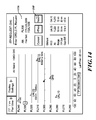
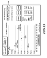
Next view button 160, the process continues on to the third step of the ITP request process as shown inFIGURE 14 . Theprocessor 24 generates and displays ITP clearance request text based on the selected valid reference aircraft and the selected valid flight level. The ITP clearance request text is displayed within theITP guidance section 116. The format of the clearance request text is consistent with recent International Civil Aviation Organization (ICAO) standards. The ITP clearance request text includes an altitude value, in thisexample FL 330 and free text which is formatted accordingly. Then, the pilot either manually enters the clearance text into a data link interface (e.g. communications system 32) or theprocessor 24 uploads the clearance request text automatically and transmits it to the ATC via thecommunications system 32. A Controller Pilot Data Link Communications (CPDLC) application is included for sending requests to and receive clearances from ATC. The CPDLC is typically hosted in a Multi-Function Display (MFD) or a Flight Management System (FMS) Control Display Unit (CDU). Manual ITP flight level change requests are made via data link in a manner similar to a standard flight level change request, but with additional ITP-specific information entered in the free text fields. This information may be entered on more than one free text line if necessary. If an automatic transmission of the ITP clerance request is implemented within the ITP guidance section 116 (instead of FMS CDU or MFD implementation), a "SEND" control is implemented in step 3 of the ITP process. The control is preferably positioned adjacent to the free text data. The altitude request (e.g., Climb to FL 360) is appended to the ITP free text clearance data. The ITP free text data in any implementation would be formatted according to ICAO standards. After transmission of the ITP clearance request, theprocessor 24 presents pilot responsibilities while awaiting ATC clearance and what is to be performed once clearance is received. This information is presented in theITP guidance section 116, seeFIGURE 15 . -
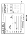
FIGURE 16 illustrates when one or more of the selected reference aircraft fail to satisfy ITP criteria after the clearance has been requested and sent to ATC. Theprocessor 24 changes the display of the reference aircraft that now fails to satisfy ITP initiation criteria. In this example, the icon and associated tag information associated with the now failing reference aircraft turn to blue. Also, theadvisory message section 118 provides information why the reference aircraft fails to satisfy the ITP criteria. In one embodiment, theprocessor 24 generates an auditory message that is outputted via headphones or speakers within the cockpit for advising the pilot that they must verify the ITP criteria for reference aircraft. Other warnings may be provided. - In an alternative embodiment, step 4 of the ITP procedure guidance is only displayed to the user once the ITP climb/descent has started. It provides guidance on the necessary pilot actions (e.g., climb at 300 fpm or more, maintain constant cruise Mach number). In addition, visual and aural annunciations are provided if any necessary ITP conditions are breached during the ITP maneuver (e.g. less than 10 NM ITP distance). In one embodiment, the ITP reference aircraft transition from green to blue color and an ITP advisory message such as "ITP Distance < 10 NM, Contact ATC" is provided in the
advisory message section 118. An aural alert could also be provided simultaneously. - The embodiments of the invention in which an exclusive property or privilege is claimed are defined as follows:
Claims (10)
- A method comprising:receiving at a user interface located on a host aircraft a user selection of one or more display parameters;receiving target aircraft information from a communications system on the host aircraft;generating a graphical user interface display for presentation on a display coupled to a processing device on the host aircraft, the graphical user interface display comprising:a main section configured to present one of a plan view or In-Trail Procedure (ITP) vertical profile view;an ITP procedural guidance section;a target status section; andan advisory message section,wherein one or more target icons based on the received target aircraft information and the received one or more display parameters are presented in the main section,wherein the ITP vertical profile view includes ITP distance information;receiving a user selection of a desired flight level (FL);uniquely identifying the current FL of the host aircraft;if all participating target aircraft within a predefined lateral envelope relative to the host aircraft, between the host aircraft's current flight level and the selected desired FL, satisfy ITP initiation criteria, then uniquely identifying in a first way at least one of the desired FL from the other flight levels or target icons associated with target aircraft that are located between the FL of the host aircraft and the selected desired FL from other target icons; andif one of the participating target aircraft within the predefined lateral envelope relative to the host aircraft, between the host aircraft's current flight level and the selected desired FL, does not satisfy ITP initiation criteria, then uniquely identifying in a second way at least one of the desired FL from the other flight levels or target icons associated with target aircraft that are located between the FL of the host aircraft and the selected desired FL from other target icons.
- The method of Claim 1, further comprising automatically formulating ITP clearance text and displaying the ITP clearance text in the ITP guidance section based on the selected desired FL and at least one of an automatic or manual selection of one or more target aircraft icons displayed on the ITP vertical profile view between the host aircraft's current flight level and the selected desired FL,
wherein the target aircraft icons are associated with target aircraft located within the predefined lateral envelope of the host aircraft and the target aircraft satisfy ITP initiation criteria. - The method of Claim 2, further comprising:automatically sending a request for altitude change based on the displayed ITP clearance text; and
- The method of Claim 3, further comprising outputting at least one of a visual or audible alert if the aircraft included in the ITP clearance text fails to satisfy the ITP initiation criteria.
- The method of Claim 2, further comprising:displaying post ITP clearance approval instructions in the ITP guidance section; anduniquely identifying target aircraft icons associated with target aircraft that do not satisfy ITP initiation criteria,wherein the one or more display parameters comprise the lateral envelope and a vertical envelope.
- The method of Claim 1, further comprising:receiving a user selection of a target aircraft icon displayed in the main section;displaying information in the target status section, the information relating to the aircraft associated with the selected target aircraft icon,wherein the displayed information comprises at least one of flight identification (ID), altitude, range, ITP distance, ground speed differential and groundspeed differential indicator with the host aircraft; anddisplaying information in the advisory message section if the associated aircraft fails to satisfy ITP initiation criteria.
- A system comprising:a means for receiving at a user interface (30) located on a host aircraft a user selection of one or more display parameters;a means for receiving target aircraft information from a communications system (32) on the host aircraft (20);a means for generating a graphical user interface display for presentation on a display coupled to a processing device (24) on the host aircraft, the graphical user interface display comprising:a main section (52) configured to present one of a plan view or In-Trail Procedure (ITP) vertical profile view;an ITP guidance section (54);a target status section (56); andan advisory message section (58),wherein one or more target icons based on the received target information and the received one or more display parameters are presented in the main section,wherein the ITP vertical profile view includes ITP distance information;a means for receiving a user selection of a desired flight level (FL);a means for uniquely identifying the current FL of the host aircraft;a means for uniquely identifying in a first way at least one of the desired FL from the other flight levels or target icons associated with target aircraft that are located between the FL of the host aircraft and the selected desired FL from other target icons, if all participating target aircraft within a predefined lateral envelope of the host aircraft, between the host aircraft's current flight level and the selected desired FL satisfy ITP initiation criteria; anda means for uniquely identifying in a second way at least one of the desired FL from the other flight levels or target icons associated with target aircraft that are located between the FL of the host aircraft and the selected desired FL from other target icons, if one of the participating target aircraft within the predefined lateral envelope relative to the host aircraft, between the host aircraft's current flight level and the selected desired FL does not satisfy ITP initiation criteria.
- The system of Claim 7, further comprising a means for automatically formulating ITP clearance text and displaying the ITP clearance text in the ITP guidance section based on the selected desired FL and at least one of an automatic or manual selection of one or more target aircraft icons displayed on the ITP vertical profile view between the host aircraft's current flight level and the selected desired FL,
wherein the target aircraft icons are associated with target aircraft located within the predefined lateral envelope of the host aircraft and the target aircraft satisfy ITP initiation criteria. - The system of Claim 8, further comprising:a means for displaying post ITP clearance approval instructions in the ITP guidance section;a means for automatically sending a request for altitude change based on the displayed ITP clearance text;a means for outputting at least one of a visual or audible alert if the aircraft included in the ITP clearance text fails to satisfy the ITP initiation criteria;a means for uniquely identifying target aircraft icons associated with target aircraft that do not satisfy ITP initiation criteria.
- The system of Claim 9, wherein the displayed information comprises at least one of flight identification (ID), altitude, range, ITP distance, ground speed differential, and groundspeed differential indicator with the host aircraft, further comprising a means for displaying information in the advisory message section if the associated aircraft fails to satisfy ITP initiation criteria.
Applications Claiming Priority (2)
| Application Number | Priority Date | Filing Date | Title |
|---|---|---|---|
| US34542410P | 2010-05-17 | 2010-05-17 | |
| US12/912,183 US8660713B2 (en) | 2010-05-17 | 2010-10-26 | Methods and systems for an improved in-trail procedures display |
Publications (3)
| Publication Number | Publication Date |
|---|---|
| EP2388759A2 true EP2388759A2 (en) | 2011-11-23 |
| EP2388759A3 EP2388759A3 (en) | 2013-03-20 |
| EP2388759B1 EP2388759B1 (en) | 2017-07-19 |
Family
ID=44558449
Family Applications (1)
| Application Number | Title | Priority Date | Filing Date |
|---|---|---|---|
| EP11155504.1A Active EP2388759B1 (en) | 2010-05-17 | 2011-02-22 | Methods and systems for a in-trail procedures display |
Country Status (3)
| Country | Link |
|---|---|
| US (1) | US8660713B2 (en) |
| EP (1) | EP2388759B1 (en) |
| CN (1) | CN102254452B (en) |
Cited By (7)
| Publication number | Priority date | Publication date | Assignee | Title |
|---|---|---|---|---|
| EP2618321A3 (en) * | 2012-01-20 | 2014-01-01 | Honeywell International Inc. | System and method for displaying degraded traffic data on an in-trail procedure (ITP) display) |
| US8781649B2 (en) | 2012-03-19 | 2014-07-15 | Honeywell International Inc. | System and method for displaying in-trail procedure (ITP) opportunities on an aircraft cockpit display |
| EP2790167A3 (en) * | 2013-04-09 | 2014-12-03 | Honeywell International Inc. | System and method for displaying symbology on an in-trail procedure display graphically and textually representative of a vertical traffic scenario and air- traffic-control negotiation |
| FR3015024A1 (en) * | 2013-12-18 | 2015-06-19 | Dassault Aviat | SYSTEM FOR AIDING THE PREPARATION OF A MISSION OF SEVERAL AIRCRAFT OR AIRCRAFT GROUPS AND METHOD |
| US9330573B2 (en) | 2009-06-25 | 2016-05-03 | Honeywell International Inc. | Automated decision aid tool for prompting a pilot to request a flight level change |
| EP2801965B1 (en) * | 2013-05-10 | 2018-06-13 | Honeywell International Inc. | A system and method for providing advisory support information on downlink clearance and reports |
| EP3376489A1 (en) * | 2017-03-13 | 2018-09-19 | Honeywell International Inc. | Systems and methods for requesting flight plan changes onboard an aircraft during flight |
Families Citing this family (20)
| Publication number | Priority date | Publication date | Assignee | Title |
|---|---|---|---|---|
| US8271152B2 (en) * | 2010-03-10 | 2012-09-18 | Honeywell International Inc. | System and method for rendering an onboard aircraft display for use with in-trail procedures |
| US8417397B2 (en) | 2010-05-05 | 2013-04-09 | Honeywell International Inc. | Vertical profile display with variable display boundaries |
| US9558668B2 (en) | 2010-10-26 | 2017-01-31 | Honeywell International Inc. | Systems and methods for improving an in-trail procedures request |
| US8626428B2 (en) * | 2011-06-28 | 2014-01-07 | Honeywell International Inc. | Selectable display of aircraft traffic on tracks |
| US8554394B2 (en) * | 2012-02-28 | 2013-10-08 | Honeywell International Inc. | System and method for rendering an aircraft cockpit display for use with an in-trail procedure (ITP) |
| US9234982B2 (en) * | 2012-08-06 | 2016-01-12 | Honeywell International Inc. | Aircraft systems and methods for displaying weather information along a flight path |
| US9297895B2 (en) * | 2012-08-30 | 2016-03-29 | Honeywell International Inc. | Systems and methods for in-trail opportunity window estimator |
| US20140222327A1 (en) * | 2013-02-04 | 2014-08-07 | Honeywell International Inc. | System and method for displaying terrain altitudes on an aircraft display |
| JP2014212479A (en) | 2013-04-19 | 2014-11-13 | ソニー株式会社 | Control device, control method, and computer program |
| US20140354455A1 (en) * | 2013-05-31 | 2014-12-04 | Honeywell International Inc. | System and method for increasing situational awareness by displaying altitude filter limit lines on a vertical situation display |
| US20160049080A1 (en) * | 2014-08-13 | 2016-02-18 | Honeywell International Inc. | System and method for reducing in-trail procedure (itp) rejection ratio |
| US10026324B2 (en) | 2014-11-04 | 2018-07-17 | Honeywell International Inc. | Systems and methods for enhanced adoptive validation of ATC clearance requests |
| US10026322B2 (en) * | 2014-12-02 | 2018-07-17 | Honeywell International Inc. | Integrated controller-pilot datalink communication systems and methods for operating the same |
| US9704407B2 (en) * | 2015-01-21 | 2017-07-11 | Honeywell International Inc. | Aircraft systems and methods with enhanced NOTAMs |
| CN104777464B (en) * | 2015-04-20 | 2017-03-29 | 中国民航大学 | The method that many radar data HWIL simulations are realized using ADS B datas |
| US10127821B2 (en) * | 2015-06-24 | 2018-11-13 | Honeywell International Inc. | Aircraft systems and methods to improve airport traffic management |
| US9646504B2 (en) * | 2015-10-08 | 2017-05-09 | The Boeing Company | Flight deck displays to enable visual separation standard |
| US9773421B2 (en) | 2015-10-19 | 2017-09-26 | Honeywell International Inc. | Aircraft maneuver data management system |
| US10490089B2 (en) | 2017-07-12 | 2019-11-26 | Honeywell International Inc. | Cockpit display of traffic information (CDTI) assisted visual separation employing a vertical situation display |
| CN112037583B (en) * | 2020-09-02 | 2022-08-09 | 中国航空无线电电子研究所 | Optimization guiding method for aircraft altitude layer change program |
Family Cites Families (48)
| Publication number | Priority date | Publication date | Assignee | Title |
|---|---|---|---|---|
| US5383098A (en) | 1991-09-19 | 1995-01-17 | Motorola, Inc. | Shield assembly |
| US5682291A (en) | 1996-07-10 | 1997-10-28 | Dell U.S.A., L.P. | Carrier for a computer device |
| US6654078B1 (en) | 1999-02-18 | 2003-11-25 | Nec Lcd Technologies, Ltd. | Liquid crystal module mounting structure and mobile terminal mounted with the same |
| KR200218685Y1 (en) | 1999-06-28 | 2001-04-02 | 김순택 | LCD assembly |
| EP1087210B1 (en) * | 1999-09-14 | 2011-10-19 | Honeywell Inc. | Methods and apparatus for graphical display and editing of flight plans |
| US6433729B1 (en) | 1999-09-27 | 2002-08-13 | Honeywell International Inc. | System and method for displaying vertical profile of intruding traffic in two dimensions |
| US6289277B1 (en) | 1999-10-07 | 2001-09-11 | Honeywell International Inc. | Interfaces for planning vehicle routes |
| US7471995B1 (en) | 2000-05-26 | 2008-12-30 | Aerotech Research (Usa), Inc. | Transmission, receipt, combination, sorting, and presentation of vehicle specific environmental conditions and hazards information |
| WO2003005060A1 (en) | 2001-07-03 | 2003-01-16 | Honeywell International Inc. | Vertical profile display with arbitrary plane |
| US6593858B2 (en) | 2001-09-12 | 2003-07-15 | Honeywell International Inc. | Methods and apparatus for generating a vertical situational image of a vehicle |
| US6720891B2 (en) | 2001-12-26 | 2004-04-13 | The Boeing Company | Vertical situation display terrain/waypoint swath, range to target speed, and blended airplane reference |
| US6616106B1 (en) | 2002-02-21 | 2003-09-09 | Hewlett-Packard Development Company, L.P. | System and means for the secure mounting of a device bracket |
| KR100471064B1 (en) | 2002-06-11 | 2005-03-10 | 삼성전자주식회사 | Displaying apparatus |
| DE60310518T2 (en) | 2003-02-27 | 2007-09-27 | Sony Ericsson Mobile Communications Ab | Compact display module |
| US20050049762A1 (en) | 2003-08-26 | 2005-03-03 | Dwyer David B. | Integrated flight management and textual air traffic control display system and method |
| US7188007B2 (en) | 2003-12-24 | 2007-03-06 | The Boeing Company | Apparatuses and methods for displaying and receiving tactical and strategic flight guidance information |
| US7004614B2 (en) | 2004-02-20 | 2006-02-28 | Au Optronics Corp. | Backlight module |
| US7179990B2 (en) | 2004-07-31 | 2007-02-20 | Sumitomo Wiring Systems, Ltd. | Electric junction box |
| TWI261137B (en) | 2004-12-02 | 2006-09-01 | Au Optronics Corp | Frame and liquid crystal display module utilizing the same |
| TWI265768B (en) | 2005-04-12 | 2006-11-01 | Asustek Comp Inc | Hard disk drive holding device |
| US7236357B2 (en) | 2005-07-13 | 2007-06-26 | Inventec Corporation | Replacing-type upper cover plate structure of notebook computer |
| US20070052100A1 (en) | 2005-09-07 | 2007-03-08 | Nokia Corporation | Spring clip for a portable electronic device |
| JP2007165765A (en) | 2005-12-16 | 2007-06-28 | Yazaki Corp | Box lock structure |
| FR2897975B1 (en) | 2006-02-28 | 2008-10-17 | Airbus France Sas | METHOD AND DEVICE FOR ASSISTING THE CONTROL OF AN AIRCRAFT. |
| US7712621B2 (en) | 2006-05-22 | 2010-05-11 | D-Link Corporation | Housing with hidden ventilation holes |
| US20080013087A1 (en) | 2006-07-14 | 2008-01-17 | Dell Products L.P. | Alignment form |
| KR101385231B1 (en) | 2006-08-24 | 2014-04-14 | 삼성디스플레이 주식회사 | Flat panel display |
| TWM317596U (en) | 2006-12-29 | 2007-08-21 | Universal Scient Ind Co Ltd | Hard disk removable device |
| US7979199B2 (en) | 2007-01-10 | 2011-07-12 | Honeywell International Inc. | Method and system to automatically generate a clearance request to deviate from a flight plan |
| US7570178B1 (en) * | 2007-03-15 | 2009-08-04 | Rockwell Collins, Inc. | Traffic display |
| US7940518B2 (en) | 2007-04-03 | 2011-05-10 | Pandigital, Inc. | Dual frame electronic display |
| US8428793B2 (en) | 2007-07-31 | 2013-04-23 | Honeywell International Inc. | Automatic downlink messaging during emergency flight situations |
| US9257047B2 (en) | 2007-12-12 | 2016-02-09 | The Boeing Company | Computation of new aircraft trajectory using time factor |
| TWM333638U (en) | 2007-12-13 | 2008-06-01 | Universal Scient Ind Co Ltd | Hard disk fixing device |
| US8101859B2 (en) | 2008-01-03 | 2012-01-24 | Apple Inc. | Metal retaining features for handheld electronic device casing |
| US8285427B2 (en) | 2008-07-31 | 2012-10-09 | Honeywell International Inc. | Flight deck communication and display system |
| US9170125B2 (en) | 2008-09-04 | 2015-10-27 | The Boeing Company | Presenting weather information on a display |
| US20100194628A1 (en) | 2009-02-05 | 2010-08-05 | Honeywell International Inc. | Systems and methods for displaying radar-measured turbulence intensity on a vertical display |
| US8504220B2 (en) | 2009-04-07 | 2013-08-06 | Aviation Communication & Surveillance Systems Llc | Systems and methods for providing an in-trail procedure speed director |
| FR2945360B1 (en) | 2009-05-07 | 2011-07-15 | Airbus France | METHOD AND DEVICE FOR FACILITATING REALIZATION OF ALTITUDE CHANGE MANEUVER WITH REDUCED SPACES OF AN AIRCRAFT |
| US9330573B2 (en) | 2009-06-25 | 2016-05-03 | Honeywell International Inc. | Automated decision aid tool for prompting a pilot to request a flight level change |
| US8203465B2 (en) | 2009-07-13 | 2012-06-19 | The Boeing Company | Filtering aircraft traffic for display to a pilot |
| JP2011180237A (en) | 2010-02-26 | 2011-09-15 | Hitachi Consumer Electronics Co Ltd | Video display device |
| US10429844B2 (en) | 2010-04-29 | 2019-10-01 | Aviation Communication & Surveillance Systems Llc | Systems and methods for providing a vertical profile for an in-trail procedure |
| US9135829B2 (en) | 2010-04-30 | 2015-09-15 | The Boeing Company | Distance separation criteria indicator |
| EP2588371A4 (en) | 2010-07-02 | 2017-05-17 | Sandel Avionics, INC. | Aircraft hover system and method |
| US9558668B2 (en) | 2010-10-26 | 2017-01-31 | Honeywell International Inc. | Systems and methods for improving an in-trail procedures request |
| US20120203448A1 (en) | 2011-02-07 | 2012-08-09 | Honeywell International Inc. | Systems and methods for providing itp clearance information |
-
2010
- 2010-10-26 US US12/912,183 patent/US8660713B2/en not_active Expired - Fee Related
-
2011
- 2011-02-22 EP EP11155504.1A patent/EP2388759B1/en active Active
- 2011-03-16 CN CN201110063036.0A patent/CN102254452B/en not_active Expired - Fee Related
Cited By (9)
| Publication number | Priority date | Publication date | Assignee | Title |
|---|---|---|---|---|
| US9330573B2 (en) | 2009-06-25 | 2016-05-03 | Honeywell International Inc. | Automated decision aid tool for prompting a pilot to request a flight level change |
| EP2618321A3 (en) * | 2012-01-20 | 2014-01-01 | Honeywell International Inc. | System and method for displaying degraded traffic data on an in-trail procedure (ITP) display) |
| US8781649B2 (en) | 2012-03-19 | 2014-07-15 | Honeywell International Inc. | System and method for displaying in-trail procedure (ITP) opportunities on an aircraft cockpit display |
| EP2790167A3 (en) * | 2013-04-09 | 2014-12-03 | Honeywell International Inc. | System and method for displaying symbology on an in-trail procedure display graphically and textually representative of a vertical traffic scenario and air- traffic-control negotiation |
| US9171472B2 (en) | 2013-04-09 | 2015-10-27 | Honeywell International Inc. | System and method for displaying symbology on an in-trail procedure display graphically and textually representative of a vertical traffic scenario and air-traffic-control negotiation |
| EP2801965B1 (en) * | 2013-05-10 | 2018-06-13 | Honeywell International Inc. | A system and method for providing advisory support information on downlink clearance and reports |
| FR3015024A1 (en) * | 2013-12-18 | 2015-06-19 | Dassault Aviat | SYSTEM FOR AIDING THE PREPARATION OF A MISSION OF SEVERAL AIRCRAFT OR AIRCRAFT GROUPS AND METHOD |
| EP3376489A1 (en) * | 2017-03-13 | 2018-09-19 | Honeywell International Inc. | Systems and methods for requesting flight plan changes onboard an aircraft during flight |
| US10115315B2 (en) | 2017-03-13 | 2018-10-30 | Honeywell International Inc. | Systems and methods for requesting flight plan changes onboard an aircraft during flight |
Also Published As
| Publication number | Publication date |
|---|---|
| EP2388759B1 (en) | 2017-07-19 |
| EP2388759A3 (en) | 2013-03-20 |
| US8660713B2 (en) | 2014-02-25 |
| CN102254452A (en) | 2011-11-23 |
| CN102254452B (en) | 2015-07-08 |
| US20110282568A1 (en) | 2011-11-17 |
Similar Documents
| Publication | Publication Date | Title |
|---|---|---|
| US8660713B2 (en) | Methods and systems for an improved in-trail procedures display | |
| US8164485B2 (en) | System and method for aiding pilot preview, rehearsal, review, and real-time visual acquisition of flight mission progress | |
| CN111038715B (en) | View guidance system and method for aircraft | |
| US9171472B2 (en) | System and method for displaying symbology on an in-trail procedure display graphically and textually representative of a vertical traffic scenario and air-traffic-control negotiation | |
| EP2073186B1 (en) | Method and system for display of guidance reference for traffic situational awareness | |
| EP3509052B1 (en) | Safe speed advisories for flight deck interval management (fim) paired approach (pa) systems | |
| EP3292429B1 (en) | Aircraft wake turbulence awareness | |
| EP2485205B1 (en) | Systems and methods for providing ITP clearance information | |
| US10319239B2 (en) | Systems and methods for context based CPDLC | |
| CN105280025A (en) | Aircraft display systems and methods for providing an aircraft display for use with airport departure and arrival procedures | |
| EP2333744A2 (en) | Systems and methods employing a collision avoidance system to enhance pilot awareness | |
| CN107264820A (en) | System and method for updating ILS classifications and Decision Height | |
| CN105513430B (en) | System and method for graphically displaying adjacent rotorcraft | |
| EP3869159A1 (en) | Advanced flight guidance panel with display of future waypoints and constraints | |
| EP3470791A1 (en) | Method and system to provide contextual auto-correlation of vertical situational display objects to objects displayed on a lateral map display based on a priority scheme | |
| EP3591639A1 (en) | Aircraft hazard information system | |
| EP2151384A2 (en) | Systems and methods for improving pilot situational awareness during landing | |
| Prinzel III et al. | System and method for aiding pilot preview, rehearsal, review, and real-time visual acquisition of flight mission progress |
Legal Events
| Date | Code | Title | Description |
|---|---|---|---|
| 17P | Request for examination filed |
Effective date: 20110222 |
|
| AK | Designated contracting states |
Kind code of ref document: A2 Designated state(s): AL AT BE BG CH CY CZ DE DK EE ES FI FR GB GR HR HU IE IS IT LI LT LU LV MC MK MT NL NO PL PT RO RS SE SI SK SM TR |
|
| AX | Request for extension of the european patent |
Extension state: BA ME |
|
| PUAI | Public reference made under article 153(3) epc to a published international application that has entered the european phase |
Free format text: ORIGINAL CODE: 0009012 |
|
| PUAL | Search report despatched |
Free format text: ORIGINAL CODE: 0009013 |
|
| AK | Designated contracting states |
Kind code of ref document: A3 Designated state(s): AL AT BE BG CH CY CZ DE DK EE ES FI FR GB GR HR HU IE IS IT LI LT LU LV MC MK MT NL NO PL PT RO RS SE SI SK SM TR |
|
| AX | Request for extension of the european patent |
Extension state: BA ME |
|
| RIC1 | Information provided on ipc code assigned before grant |
Ipc: G08G 5/04 20060101ALN20130212BHEP Ipc: G08G 5/00 20060101AFI20130212BHEP |
|
| 17Q | First examination report despatched |
Effective date: 20130726 |
|
| RAP1 | Party data changed (applicant data changed or rights of an application transferred) |
Owner name: HONEYWELL INTERNATIONAL INC. |
|
| GRAP | Despatch of communication of intention to grant a patent |
Free format text: ORIGINAL CODE: EPIDOSNIGR1 |
|
| RIC1 | Information provided on ipc code assigned before grant |
Ipc: G08G 5/04 20060101ALN20170215BHEP Ipc: G08G 5/00 20060101AFI20170215BHEP |
|
| INTG | Intention to grant announced |
Effective date: 20170303 |
|
| GRAS | Grant fee paid |
Free format text: ORIGINAL CODE: EPIDOSNIGR3 |
|
| GRAA | (expected) grant |
Free format text: ORIGINAL CODE: 0009210 |
|
| AK | Designated contracting states |
Kind code of ref document: B1 Designated state(s): AL AT BE BG CH CY CZ DE DK EE ES FI FR GB GR HR HU IE IS IT LI LT LU LV MC MK MT NL NO PL PT RO RS SE SI SK SM TR |
|
| REG | Reference to a national code |
Ref country code: GB Ref legal event code: FG4D |
|
| REG | Reference to a national code |
Ref country code: CH Ref legal event code: EP |
|
| REG | Reference to a national code |
Ref country code: IE Ref legal event code: FG4D |
|
| REG | Reference to a national code |
Ref country code: AT Ref legal event code: REF Ref document number: 911075 Country of ref document: AT Kind code of ref document: T Effective date: 20170815 |
|
| REG | Reference to a national code |
Ref country code: DE Ref legal event code: R096 Ref document number: 602011039627 Country of ref document: DE |
|
| REG | Reference to a national code |
Ref country code: NL Ref legal event code: MP Effective date: 20170719 |
|
| REG | Reference to a national code |
Ref country code: LT Ref legal event code: MG4D |
|
| REG | Reference to a national code |
Ref country code: AT Ref legal event code: MK05 Ref document number: 911075 Country of ref document: AT Kind code of ref document: T Effective date: 20170719 |
|
| PG25 | Lapsed in a contracting state [announced via postgrant information from national office to epo] |
Ref country code: LT Free format text: LAPSE BECAUSE OF FAILURE TO SUBMIT A TRANSLATION OF THE DESCRIPTION OR TO PAY THE FEE WITHIN THE PRESCRIBED TIME-LIMIT Effective date: 20170719 Ref country code: AT Free format text: LAPSE BECAUSE OF FAILURE TO SUBMIT A TRANSLATION OF THE DESCRIPTION OR TO PAY THE FEE WITHIN THE PRESCRIBED TIME-LIMIT Effective date: 20170719 Ref country code: FI Free format text: LAPSE BECAUSE OF FAILURE TO SUBMIT A TRANSLATION OF THE DESCRIPTION OR TO PAY THE FEE WITHIN THE PRESCRIBED TIME-LIMIT Effective date: 20170719 Ref country code: HR Free format text: LAPSE BECAUSE OF FAILURE TO SUBMIT A TRANSLATION OF THE DESCRIPTION OR TO PAY THE FEE WITHIN THE PRESCRIBED TIME-LIMIT Effective date: 20170719 Ref country code: SE Free format text: LAPSE BECAUSE OF FAILURE TO SUBMIT A TRANSLATION OF THE DESCRIPTION OR TO PAY THE FEE WITHIN THE PRESCRIBED TIME-LIMIT Effective date: 20170719 Ref country code: NL Free format text: LAPSE BECAUSE OF FAILURE TO SUBMIT A TRANSLATION OF THE DESCRIPTION OR TO PAY THE FEE WITHIN THE PRESCRIBED TIME-LIMIT Effective date: 20170719 Ref country code: NO Free format text: LAPSE BECAUSE OF FAILURE TO SUBMIT A TRANSLATION OF THE DESCRIPTION OR TO PAY THE FEE WITHIN THE PRESCRIBED TIME-LIMIT Effective date: 20171019 |
|
| REG | Reference to a national code |
Ref country code: FR Ref legal event code: PLFP Year of fee payment: 8 |
|
| PG25 | Lapsed in a contracting state [announced via postgrant information from national office to epo] |
Ref country code: BG Free format text: LAPSE BECAUSE OF FAILURE TO SUBMIT A TRANSLATION OF THE DESCRIPTION OR TO PAY THE FEE WITHIN THE PRESCRIBED TIME-LIMIT Effective date: 20171019 Ref country code: GR Free format text: LAPSE BECAUSE OF FAILURE TO SUBMIT A TRANSLATION OF THE DESCRIPTION OR TO PAY THE FEE WITHIN THE PRESCRIBED TIME-LIMIT Effective date: 20171020 Ref country code: PL Free format text: LAPSE BECAUSE OF FAILURE TO SUBMIT A TRANSLATION OF THE DESCRIPTION OR TO PAY THE FEE WITHIN THE PRESCRIBED TIME-LIMIT Effective date: 20170719 Ref country code: RS Free format text: LAPSE BECAUSE OF FAILURE TO SUBMIT A TRANSLATION OF THE DESCRIPTION OR TO PAY THE FEE WITHIN THE PRESCRIBED TIME-LIMIT Effective date: 20170719 Ref country code: ES Free format text: LAPSE BECAUSE OF FAILURE TO SUBMIT A TRANSLATION OF THE DESCRIPTION OR TO PAY THE FEE WITHIN THE PRESCRIBED TIME-LIMIT Effective date: 20170719 Ref country code: LV Free format text: LAPSE BECAUSE OF FAILURE TO SUBMIT A TRANSLATION OF THE DESCRIPTION OR TO PAY THE FEE WITHIN THE PRESCRIBED TIME-LIMIT Effective date: 20170719 Ref country code: IS Free format text: LAPSE BECAUSE OF FAILURE TO SUBMIT A TRANSLATION OF THE DESCRIPTION OR TO PAY THE FEE WITHIN THE PRESCRIBED TIME-LIMIT Effective date: 20171119 |
|
| REG | Reference to a national code |
Ref country code: DE Ref legal event code: R097 Ref document number: 602011039627 Country of ref document: DE |
|
| PG25 | Lapsed in a contracting state [announced via postgrant information from national office to epo] |
Ref country code: DK Free format text: LAPSE BECAUSE OF FAILURE TO SUBMIT A TRANSLATION OF THE DESCRIPTION OR TO PAY THE FEE WITHIN THE PRESCRIBED TIME-LIMIT Effective date: 20170719 Ref country code: CZ Free format text: LAPSE BECAUSE OF FAILURE TO SUBMIT A TRANSLATION OF THE DESCRIPTION OR TO PAY THE FEE WITHIN THE PRESCRIBED TIME-LIMIT Effective date: 20170719 Ref country code: RO Free format text: LAPSE BECAUSE OF FAILURE TO SUBMIT A TRANSLATION OF THE DESCRIPTION OR TO PAY THE FEE WITHIN THE PRESCRIBED TIME-LIMIT Effective date: 20170719 |
|
| PLBE | No opposition filed within time limit |
Free format text: ORIGINAL CODE: 0009261 |
|
| STAA | Information on the status of an ep patent application or granted ep patent |
Free format text: STATUS: NO OPPOSITION FILED WITHIN TIME LIMIT |
|
| PG25 | Lapsed in a contracting state [announced via postgrant information from national office to epo] |
Ref country code: SM Free format text: LAPSE BECAUSE OF FAILURE TO SUBMIT A TRANSLATION OF THE DESCRIPTION OR TO PAY THE FEE WITHIN THE PRESCRIBED TIME-LIMIT Effective date: 20170719 Ref country code: IT Free format text: LAPSE BECAUSE OF FAILURE TO SUBMIT A TRANSLATION OF THE DESCRIPTION OR TO PAY THE FEE WITHIN THE PRESCRIBED TIME-LIMIT Effective date: 20170719 Ref country code: EE Free format text: LAPSE BECAUSE OF FAILURE TO SUBMIT A TRANSLATION OF THE DESCRIPTION OR TO PAY THE FEE WITHIN THE PRESCRIBED TIME-LIMIT Effective date: 20170719 Ref country code: SK Free format text: LAPSE BECAUSE OF FAILURE TO SUBMIT A TRANSLATION OF THE DESCRIPTION OR TO PAY THE FEE WITHIN THE PRESCRIBED TIME-LIMIT Effective date: 20170719 |
|
| 26N | No opposition filed |
Effective date: 20180420 |
|
| PG25 | Lapsed in a contracting state [announced via postgrant information from national office to epo] |
Ref country code: SI Free format text: LAPSE BECAUSE OF FAILURE TO SUBMIT A TRANSLATION OF THE DESCRIPTION OR TO PAY THE FEE WITHIN THE PRESCRIBED TIME-LIMIT Effective date: 20170719 |
|
| REG | Reference to a national code |
Ref country code: CH Ref legal event code: PL |
|
| PG25 | Lapsed in a contracting state [announced via postgrant information from national office to epo] |
Ref country code: MC Free format text: LAPSE BECAUSE OF FAILURE TO SUBMIT A TRANSLATION OF THE DESCRIPTION OR TO PAY THE FEE WITHIN THE PRESCRIBED TIME-LIMIT Effective date: 20170719 |
|
| REG | Reference to a national code |
Ref country code: IE Ref legal event code: MM4A |
|
| REG | Reference to a national code |
Ref country code: BE Ref legal event code: MM Effective date: 20180228 |
|
| PG25 | Lapsed in a contracting state [announced via postgrant information from national office to epo] |
Ref country code: LI Free format text: LAPSE BECAUSE OF NON-PAYMENT OF DUE FEES Effective date: 20180228 Ref country code: CH Free format text: LAPSE BECAUSE OF NON-PAYMENT OF DUE FEES Effective date: 20180228 Ref country code: LU Free format text: LAPSE BECAUSE OF NON-PAYMENT OF DUE FEES Effective date: 20180222 |
|
| PG25 | Lapsed in a contracting state [announced via postgrant information from national office to epo] |
Ref country code: IE Free format text: LAPSE BECAUSE OF NON-PAYMENT OF DUE FEES Effective date: 20180222 |
|
| PG25 | Lapsed in a contracting state [announced via postgrant information from national office to epo] |
Ref country code: BE Free format text: LAPSE BECAUSE OF NON-PAYMENT OF DUE FEES Effective date: 20180228 |
|
| PGFP | Annual fee paid to national office [announced via postgrant information from national office to epo] |
Ref country code: GB Payment date: 20190227 Year of fee payment: 9 |
|
| PGFP | Annual fee paid to national office [announced via postgrant information from national office to epo] |
Ref country code: DE Payment date: 20190401 Year of fee payment: 9 |
|
| PG25 | Lapsed in a contracting state [announced via postgrant information from national office to epo] |
Ref country code: MT Free format text: LAPSE BECAUSE OF NON-PAYMENT OF DUE FEES Effective date: 20180222 |
|
| PG25 | Lapsed in a contracting state [announced via postgrant information from national office to epo] |
Ref country code: TR Free format text: LAPSE BECAUSE OF FAILURE TO SUBMIT A TRANSLATION OF THE DESCRIPTION OR TO PAY THE FEE WITHIN THE PRESCRIBED TIME-LIMIT Effective date: 20170719 |
|
| PG25 | Lapsed in a contracting state [announced via postgrant information from national office to epo] |
Ref country code: PT Free format text: LAPSE BECAUSE OF FAILURE TO SUBMIT A TRANSLATION OF THE DESCRIPTION OR TO PAY THE FEE WITHIN THE PRESCRIBED TIME-LIMIT Effective date: 20170719 Ref country code: HU Free format text: LAPSE BECAUSE OF FAILURE TO SUBMIT A TRANSLATION OF THE DESCRIPTION OR TO PAY THE FEE WITHIN THE PRESCRIBED TIME-LIMIT; INVALID AB INITIO Effective date: 20110222 |
|
| PG25 | Lapsed in a contracting state [announced via postgrant information from national office to epo] |
Ref country code: CY Free format text: LAPSE BECAUSE OF FAILURE TO SUBMIT A TRANSLATION OF THE DESCRIPTION OR TO PAY THE FEE WITHIN THE PRESCRIBED TIME-LIMIT Effective date: 20170719 Ref country code: MK Free format text: LAPSE BECAUSE OF NON-PAYMENT OF DUE FEES Effective date: 20170719 |
|
| PG25 | Lapsed in a contracting state [announced via postgrant information from national office to epo] |
Ref country code: AL Free format text: LAPSE BECAUSE OF FAILURE TO SUBMIT A TRANSLATION OF THE DESCRIPTION OR TO PAY THE FEE WITHIN THE PRESCRIBED TIME-LIMIT Effective date: 20170719 |
|
| REG | Reference to a national code |
Ref country code: DE Ref legal event code: R119 Ref document number: 602011039627 Country of ref document: DE |
|
| GBPC | Gb: european patent ceased through non-payment of renewal fee |
Effective date: 20200222 |
|
| PG25 | Lapsed in a contracting state [announced via postgrant information from national office to epo] |
Ref country code: DE Free format text: LAPSE BECAUSE OF NON-PAYMENT OF DUE FEES Effective date: 20200901 Ref country code: GB Free format text: LAPSE BECAUSE OF NON-PAYMENT OF DUE FEES Effective date: 20200222 |
|
| P01 | Opt-out of the competence of the unified patent court (upc) registered |
Effective date: 20230525 |
|
| PGFP | Annual fee paid to national office [announced via postgrant information from national office to epo] |
Ref country code: FR Payment date: 20250224 Year of fee payment: 15 |