EP2388648A1 - Camera module - Google Patents
Camera module Download PDFInfo
- Publication number
- EP2388648A1 EP2388648A1 EP11164028A EP11164028A EP2388648A1 EP 2388648 A1 EP2388648 A1 EP 2388648A1 EP 11164028 A EP11164028 A EP 11164028A EP 11164028 A EP11164028 A EP 11164028A EP 2388648 A1 EP2388648 A1 EP 2388648A1
- Authority
- EP
- European Patent Office
- Prior art keywords
- lens barrel
- sealing member
- camera module
- housing
- present
- Prior art date
- Legal status (The legal status is an assumption and is not a legal conclusion. Google has not performed a legal analysis and makes no representation as to the accuracy of the status listed.)
- Withdrawn
Links
- 238000007789 sealing Methods 0.000 claims abstract description 32
- 239000000463 material Substances 0.000 claims description 12
- 230000002093 peripheral effect Effects 0.000 claims description 11
- 239000002210 silicon-based material Substances 0.000 claims description 3
- 239000007788 liquid Substances 0.000 description 8
- 230000008901 benefit Effects 0.000 description 3
- 238000000034 method Methods 0.000 description 3
- 238000007792 addition Methods 0.000 description 2
- 238000002347 injection Methods 0.000 description 2
- 239000007924 injection Substances 0.000 description 2
- 238000012986 modification Methods 0.000 description 2
- 230000004048 modification Effects 0.000 description 2
- 238000006467 substitution reaction Methods 0.000 description 2
- 238000010521 absorption reaction Methods 0.000 description 1
- 239000000853 adhesive Substances 0.000 description 1
- 230000001070 adhesive effect Effects 0.000 description 1
- 230000007547 defect Effects 0.000 description 1
- 230000009977 dual effect Effects 0.000 description 1
- 230000000694 effects Effects 0.000 description 1
- XLYOFNOQVPJJNP-UHFFFAOYSA-N water Substances O XLYOFNOQVPJJNP-UHFFFAOYSA-N 0.000 description 1
Images

Classifications
-
- G—PHYSICS
- G03—PHOTOGRAPHY; CINEMATOGRAPHY; ANALOGOUS TECHNIQUES USING WAVES OTHER THAN OPTICAL WAVES; ELECTROGRAPHY; HOLOGRAPHY
- G03B—APPARATUS OR ARRANGEMENTS FOR TAKING PHOTOGRAPHS OR FOR PROJECTING OR VIEWING THEM; APPARATUS OR ARRANGEMENTS EMPLOYING ANALOGOUS TECHNIQUES USING WAVES OTHER THAN OPTICAL WAVES; ACCESSORIES THEREFOR
- G03B17/00—Details of cameras or camera bodies; Accessories therefor
- G03B17/02—Bodies
- G03B17/08—Waterproof bodies or housings
-
- G—PHYSICS
- G03—PHOTOGRAPHY; CINEMATOGRAPHY; ANALOGOUS TECHNIQUES USING WAVES OTHER THAN OPTICAL WAVES; ELECTROGRAPHY; HOLOGRAPHY
- G03B—APPARATUS OR ARRANGEMENTS FOR TAKING PHOTOGRAPHS OR FOR PROJECTING OR VIEWING THEM; APPARATUS OR ARRANGEMENTS EMPLOYING ANALOGOUS TECHNIQUES USING WAVES OTHER THAN OPTICAL WAVES; ACCESSORIES THEREFOR
- G03B17/00—Details of cameras or camera bodies; Accessories therefor
- G03B17/02—Bodies
-
- H—ELECTRICITY
- H04—ELECTRIC COMMUNICATION TECHNIQUE
- H04N—PICTORIAL COMMUNICATION, e.g. TELEVISION
- H04N23/00—Cameras or camera modules comprising electronic image sensors; Control thereof
- H04N23/50—Constructional details
- H04N23/55—Optical parts specially adapted for electronic image sensors; Mounting thereof
-
- G—PHYSICS
- G03—PHOTOGRAPHY; CINEMATOGRAPHY; ANALOGOUS TECHNIQUES USING WAVES OTHER THAN OPTICAL WAVES; ELECTROGRAPHY; HOLOGRAPHY
- G03B—APPARATUS OR ARRANGEMENTS FOR TAKING PHOTOGRAPHS OR FOR PROJECTING OR VIEWING THEM; APPARATUS OR ARRANGEMENTS EMPLOYING ANALOGOUS TECHNIQUES USING WAVES OTHER THAN OPTICAL WAVES; ACCESSORIES THEREFOR
- G03B17/00—Details of cameras or camera bodies; Accessories therefor
- G03B17/02—Bodies
- G03B17/12—Bodies with means for supporting objectives, supplementary lenses, filters, masks, or turrets
-
- H—ELECTRICITY
- H04—ELECTRIC COMMUNICATION TECHNIQUE
- H04N—PICTORIAL COMMUNICATION, e.g. TELEVISION
- H04N23/00—Cameras or camera modules comprising electronic image sensors; Control thereof
- H04N23/50—Constructional details
- H04N23/51—Housings
Definitions
- the embodiment relates to a camera module.
- a camera module generally has a structure in which a lens and a housing are assembled by a screw and then, the circumference of the lens is fixed by bonding.
- the present invention has been made in an effort to provide a camera module capable of completely sealing a housing and a lens during the assembly thereof.
- a camera module including: a lens barrel having a plurality of lenses embedded therein to collect images of external subjects; a housing receiving the lens barrel; a sealing member provided between the lens barrel and the housing to seal a space therebetween; and a bonding part performing bonding treatment on a space between the lens barrel and the sealing member.
- the outer peripheral surface of the lens barrel may be provided with a screw thread and the inner peripheral surface of the sealing member may be provided with a screw groove to be engaged with the screw thread.
- the sealing member may be made of a silicon material or a rubber material.
- the sealing member and the housing may be selectively provided with a screw thread and a screw groove to be engaged with each other.
- the sealing member and the housing may be integrally formed with each other.
- FIG. 1 is an overall cross-sectional view of a camera module according to a preferred embodiment of the present invention
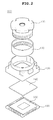
- FIG. 2 is an exploded perspective view of a camera module according to an embodiment of the present invention
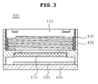
- FIG. 3 is a partially cross-sectional view of a camera module according to a preferred embodiment of the present invention.
- a camera module 100 may be configured to include a lens barrel 110, a sealing member 120, a housing 130, an IR filter 140, an image sensor 150, and a circuit board 160.
- the lens barrel 110 is configured to include a plurality of lenses embedded therein, which collects external objects into the image sensor 150 in the camera module. Meanwhile, the sealing member 120 is combined with the outside of the lens barrel 110 by a screw thread formed on the outer peripheral surface of the lens barrel 110.
- the sealing member 120 is included between the lens barrel 110 and the housing 130, which is a combining member to completely seal a space between the lens barrel 110 and the housing 130.
- the sealing member 120 prevents foreign materials and liquid from being introduced into the space between the lens barrel 110 and the housing 130 and the inside of the sealing member 120 is provided with a screw groove to be combined with the screw thread formed on the outside of the lens barrel 110.
- the sealing member 120 may be made of a material as long as it performs a waterproof function and a foreign material intercepting function such as a silicon material, a rubber material, or the like, in order to have a waterproof effect that does not break down the camera even if the camera falls into water, by preventing foreign materials and liquid from being introduced into the camera.
- the housing 130 is combined with the outside of the sealing member 120 so as to be fixedly combined with the circuit board 160 while supporting the lens barrel 110, thereby protecting the image sensor 150.
- the housing 130 may be provided to be integrated with the sealing member 120 and may be combined with the screw thread formed on the outer peripheral surface of the sealing member by the screw groove formed on the inner peripheral surface thereof.
- the IR filter 140 is to intercept infrared rays. That is, the IR filter is fixedly mounted on the housing 130 to intercept infrared rays to pass only visible rays recognized by the image sensor 150.
- the IR filter 140 may be attached to the rear of the lens barrel 110 or to the top surface of the lens barrel 110.
- the image sensor 150 is to convert external images transferred through the lens barrel 110 into electrical signals and is electrically connected to one side of the circuit board 160 through a wire bonding (not shown).
- the circuit board 160 is to transmit the electrical signals generated from the image sensor 150 to electronic devices such as a camera phone, or the like.
- the top surface of the circuit board 160 is provided with circuits that are electrically connected to the image sensor 150 and various kinds of passive devices.
- a bonding part 170 performing bonding treatment by an adhesive is formed between the space between the lens barrel 110 and the sealing member 120.
- the bonding part 170 seals the entire micro space between the lens barrel 110 and the sealing member 120 to previously prevent foreign materials and liquid from being penetrated into the camera.
- FIG. 2 is an exploded perspective view of the camera module 100 according to the preferred embodiment of the present invention.
- the sealing member 120 according to the preferred embodiment of the present invention is provided between the lens barrel 110 and the housing 130, thereby preventing foreign materials and liquid from being penetrated into the camera.
- the inner peripheral surface of the sealing member 120 is provided with a screw groove to be engaged with the screw thread formed on the outer peripheral surface of the lens barrel 110.
- the sealing member 120 may be formed by dual injection or insert injection.
- FIG. 3 is a partially cross-sectional view of the camera module 100 according to the preferred embodiment of the present invention.
- FIG. 3 shows that the outer peripheral surface of the lens barrel 110 is engaged with the inner peripheral surface of the sealing member 120 by the screw thread.
- the camera module 100 including the sealing member 120 can prevent foreign materials and liquid from being introduced from the outside beforehand by fastening the lens barrel 110 and is very effective for the camera module such as the electrical devices mounted on the outside thereof, thereby making it possible to considerably improve the reliability of the camera.
- the camera module has the structure including the sealing member between the lens barrel and the housing.
- the structure can previously prevent foreign materials and liquid from being introduced from the outside by fastening the lens barrel and is very effective for the camera module such as the electrical devices mounted on the outside thereof, thereby making it possible to considerably improve the reliability of the camera.
Landscapes
- Physics & Mathematics (AREA)
- General Physics & Mathematics (AREA)
- Engineering & Computer Science (AREA)
- Multimedia (AREA)
- Signal Processing (AREA)
- Lens Barrels (AREA)
- Studio Devices (AREA)
- Camera Bodies And Camera Details Or Accessories (AREA)
Abstract
Disclosed herein is a camera module, including: a lens barrel having a plurality of lenses embedded therein to collect images of external subjects; a housing receiving the lens barrel; a sealing member provided between the lens barrel and the housing to seal a space therebetween; and a bonding part performing bonding treatment on a space between the lens barrel and the sealing member.
Description
- This application claims the benefit of Korean Patent Application No.
10-2010-0046497, filed on May 18, 2010 - The embodiment relates to a camera module.
- Recently, a camera module generally has a structure in which a lens and a housing are assembled by a screw and then, the circumference of the lens is fixed by bonding.
- However, there are many defects in the camera module having the above structure, for example, the absorption of liquid from the outside due to a clearance caused by fixing portions.
- Further, after the lens is assembled with the housing, it is very difficult to control a bonding process during a process of assembling components at the outside thereof by using bonding and the assembling structure of the camera having mounted electrical devices, etc., on the outside thereof.
- Therefore, research into a structure of a camera module capable of effectively preventing foreign materials and liquid from being absorbed thereinto when the housing is assembled with the lens has been actively conducted.
- The present invention has been made in an effort to provide a camera module capable of completely sealing a housing and a lens during the assembly thereof.
- According to a preferred embodiment of the present invention, there is provided a camera module, including: a lens barrel having a plurality of lenses embedded therein to collect images of external subjects; a housing receiving the lens barrel; a sealing member provided between the lens barrel and the housing to seal a space therebetween; and a bonding part performing bonding treatment on a space between the lens barrel and the sealing member.
- The outer peripheral surface of the lens barrel may be provided with a screw thread and the inner peripheral surface of the sealing member may be provided with a screw groove to be engaged with the screw thread.
- The sealing member may be made of a silicon material or a rubber material.
- The sealing member and the housing may be selectively provided with a screw thread and a screw groove to be engaged with each other.
- The sealing member and the housing may be integrally formed with each other.
-
-
FIG. 1 is an overall cross-sectional view of a camera module according to a preferred embodiment of the present invention; -
FIG. 2 is an exploded perspective view of a camera module according to an embodiment of the present invention; and -
FIG. 3 is a partially cross-sectional view of a camera module according to a preferred embodiment of the present invention. - Various objects, advantages and features of the invention will become apparent from the following description of embodiments with reference to the accompanying drawings.
- The terms and words used in the present specification and claims should not be interpreted as being limited to typical meanings or dictionary definitions, but should be interpreted as having meanings and concepts relevant to the technical scope of the present invention based on the rule according to which an inventor can appropriately define the concept of the term to describe most appropriately the best method he or she knows for carrying out the invention.
- Various objects, advantages and features of the invention will become apparent from the following description of embodiments with reference to the accompanying drawings. In the specification, in adding reference numerals to components throughout the drawings, it is to be noted that like reference numerals designate like components even though components are shown in different drawings. Further, when it is determined that the detailed description of the known art related to the present invention may obscure the gist of the present invention, the detailed description thereof will be omitted.
- Hereinafter, preferred embodiments of the present invention will be described in detail with reference to the accompanying drawings.
-
FIG. 1 is an overall cross-sectional view of a camera module according to a preferred embodiment of the present invention,FIG. 2 is an exploded perspective view of a camera module according to an embodiment of the present invention, andFIG. 3 is a partially cross-sectional view of a camera module according to a preferred embodiment of the present invention. - As shown in
FIGS. 1 to 3 , acamera module 100 according to a preferred embodiment of the present invention may be configured to include alens barrel 110, asealing member 120, ahousing 130, anIR filter 140, animage sensor 150, and acircuit board 160. - The
lens barrel 110 is configured to include a plurality of lenses embedded therein, which collects external objects into theimage sensor 150 in the camera module. Meanwhile, the sealingmember 120 is combined with the outside of thelens barrel 110 by a screw thread formed on the outer peripheral surface of thelens barrel 110. - The sealing
member 120 is included between thelens barrel 110 and thehousing 130, which is a combining member to completely seal a space between thelens barrel 110 and thehousing 130. - The sealing
member 120 prevents foreign materials and liquid from being introduced into the space between thelens barrel 110 and thehousing 130 and the inside of the sealingmember 120 is provided with a screw groove to be combined with the screw thread formed on the outside of thelens barrel 110. - The sealing
member 120 may be made of a material as long as it performs a waterproof function and a foreign material intercepting function such as a silicon material, a rubber material, or the like, in order to have a waterproof effect that does not break down the camera even if the camera falls into water, by preventing foreign materials and liquid from being introduced into the camera. - The
housing 130 is combined with the outside of the sealingmember 120 so as to be fixedly combined with thecircuit board 160 while supporting thelens barrel 110, thereby protecting theimage sensor 150. Thehousing 130 may be provided to be integrated with thesealing member 120 and may be combined with the screw thread formed on the outer peripheral surface of the sealing member by the screw groove formed on the inner peripheral surface thereof. - The
IR filter 140 is to intercept infrared rays. That is, the IR filter is fixedly mounted on thehousing 130 to intercept infrared rays to pass only visible rays recognized by theimage sensor 150. TheIR filter 140 may be attached to the rear of thelens barrel 110 or to the top surface of thelens barrel 110. - The
image sensor 150 is to convert external images transferred through thelens barrel 110 into electrical signals and is electrically connected to one side of thecircuit board 160 through a wire bonding (not shown). - The
circuit board 160 is to transmit the electrical signals generated from theimage sensor 150 to electronic devices such as a camera phone, or the like. The top surface of thecircuit board 160 is provided with circuits that are electrically connected to theimage sensor 150 and various kinds of passive devices. - As described above, after the
camera module 100 is assembled, a bondingpart 170 performing bonding treatment by an adhesive is formed between the space between thelens barrel 110 and thesealing member 120. - The bonding
part 170 seals the entire micro space between thelens barrel 110 and the sealingmember 120 to previously prevent foreign materials and liquid from being penetrated into the camera. -
FIG. 2 is an exploded perspective view of thecamera module 100 according to the preferred embodiment of the present invention. The sealingmember 120 according to the preferred embodiment of the present invention is provided between thelens barrel 110 and thehousing 130, thereby preventing foreign materials and liquid from being penetrated into the camera. - The inner peripheral surface of the sealing
member 120 is provided with a screw groove to be engaged with the screw thread formed on the outer peripheral surface of thelens barrel 110. In addition, the sealingmember 120 may be formed by dual injection or insert injection. -
FIG. 3 is a partially cross-sectional view of thecamera module 100 according to the preferred embodiment of the present invention.FIG. 3 shows that the outer peripheral surface of thelens barrel 110 is engaged with the inner peripheral surface of the sealingmember 120 by the screw thread. - As described above, the
camera module 100 including thesealing member 120 can prevent foreign materials and liquid from being introduced from the outside beforehand by fastening thelens barrel 110 and is very effective for the camera module such as the electrical devices mounted on the outside thereof, thereby making it possible to considerably improve the reliability of the camera. - As set forth above, the camera module has the structure including the sealing member between the lens barrel and the housing. The structure can previously prevent foreign materials and liquid from being introduced from the outside by fastening the lens barrel and is very effective for the camera module such as the electrical devices mounted on the outside thereof, thereby making it possible to considerably improve the reliability of the camera.
- Although the preferred embodiments of the present invention have been disclosed for illustrative purposes, they are for specifically explaining the present invention and thus the camera module according to the present invention is not limited thereto, but those skilled in the art will appreciate that various modifications, additions and substitutions are possible, without departing from the scope and spirit of the invention as disclosed in the accompanying claims.
- Accordingly, such modifications, additions and substitutions should also be understood to fall within the scope of the present invention.
Claims (5)
- A camera module, comprising:a lens barrel having a plurality of lenses embedded therein to collect images from external subjects;a housing receiving the lens barrel;a sealing member provided between the lens barrel and the housing to seal a space therebetween; anda bonding part performing bonding treatment on a space between the lens barrel and the sealing member.
- The camera module as set forth in claim 1, wherein the outer peripheral surface of the lens barrel is provided with a screw thread and the inner peripheral surface of the sealing member is provided with a screw groove to be engaged with the screw thread.
- The camera module as set forth in claim 1, wherein the sealing member is made of a silicon material or a rubber material.
- The camera module as set forth in claim 1, wherein the sealing member and the housing are selectively provided with a screw thread and a screw groove to be engaged with each other.
- The camera module as set forth in claim 1, wherein the sealing member and the housing are integrally formed with each other.
Applications Claiming Priority (1)
| Application Number | Priority Date | Filing Date | Title |
|---|---|---|---|
| KR1020100046497A KR101141011B1 (en) | 2010-05-18 | 2010-05-18 | Camera Module |
Publications (1)
| Publication Number | Publication Date |
|---|---|
| EP2388648A1 true EP2388648A1 (en) | 2011-11-23 |
Family
ID=44454556
Family Applications (1)
| Application Number | Title | Priority Date | Filing Date |
|---|---|---|---|
| EP11164028A Withdrawn EP2388648A1 (en) | 2010-05-18 | 2011-04-28 | Camera module |
Country Status (3)
| Country | Link |
|---|---|
| US (1) | US8532475B2 (en) |
| EP (1) | EP2388648A1 (en) |
| KR (1) | KR101141011B1 (en) |
Cited By (1)
| Publication number | Priority date | Publication date | Assignee | Title |
|---|---|---|---|---|
| CN104969108A (en) * | 2013-02-05 | 2015-10-07 | 夏普株式会社 | Camera module |
Families Citing this family (12)
| Publication number | Priority date | Publication date | Assignee | Title |
|---|---|---|---|---|
| EP2605507B1 (en) * | 2011-12-15 | 2021-02-17 | BlackBerry Limited | Camera module having protruding lens barrel |
| CN102707408B (en) * | 2012-06-08 | 2014-07-16 | 中国科学院光电技术研究所 | Light source non-rotary focusing mechanism |
| KR102252478B1 (en) * | 2014-08-06 | 2021-05-14 | 엘지이노텍 주식회사 | Camera module |
| JP2016148812A (en) * | 2015-02-13 | 2016-08-18 | アルプス電気株式会社 | Lens drive device |
| US10341541B2 (en) | 2015-08-14 | 2019-07-02 | Gopro, Inc. | Integrated sensor and lens assembly with post-tuning optical alignment |
| CN105445888B (en) | 2015-12-21 | 2020-04-03 | 宁波舜宇光电信息有限公司 | Adjustable optical lens and camera module and calibration method thereof |
| CN105445885B (en) * | 2015-10-30 | 2019-06-18 | 宁波舜宇光电信息有限公司 | Adjustable optical lens and camera module and manufacturing method thereof |
| KR102468129B1 (en) * | 2016-06-01 | 2022-11-22 | 삼성전자주식회사 | Electronic device and manufacturing method thereof |
| CN207010790U (en) * | 2017-04-17 | 2018-02-13 | 三赢科技(深圳)有限公司 | Imaging module |
| US10443676B2 (en) * | 2017-09-20 | 2019-10-15 | Rosemount Aerospace Inc. | Isolated seeker optics |
| TWI650606B (en) * | 2017-10-31 | 2019-02-11 | 鴻海精密工業股份有限公司 | Camera module |
| CN112333351B (en) | 2019-08-05 | 2022-04-05 | 华为技术有限公司 | Camera module and mobile terminal |
Citations (6)
| Publication number | Priority date | Publication date | Assignee | Title |
|---|---|---|---|---|
| JP2005017951A (en) * | 2003-06-27 | 2005-01-20 | Kyocera Corp | Imaging device |
| JP2007225991A (en) * | 2006-02-24 | 2007-09-06 | Auto Network Gijutsu Kenkyusho:Kk | In-vehicle camera lens mounting structure |
| JP2008040349A (en) * | 2006-08-09 | 2008-02-21 | Asahi:Kk | Waterproof optical device |
| KR100862485B1 (en) * | 2007-05-21 | 2008-10-08 | 삼성전기주식회사 | Security camera with improved assembly |
| US7586702B1 (en) * | 2008-03-26 | 2009-09-08 | Fu Zhun Precision Industry (Shen Zhen) Co., Ltd. | Camera module |
| KR20090122593A (en) * | 2008-05-26 | 2009-12-01 | 삼성전기주식회사 | Camera module package |
Family Cites Families (5)
| Publication number | Priority date | Publication date | Assignee | Title |
|---|---|---|---|---|
| US7391466B2 (en) * | 2004-05-04 | 2008-06-24 | Micron Technology, Inc. | Camera module with dust trap |
| CN1885908B (en) | 2005-06-24 | 2010-04-28 | 鸿富锦精密工业(深圳)有限公司 | camera module |
| KR200467844Y1 (en) * | 2007-11-19 | 2013-07-12 | 엘지이노텍 주식회사 | Camera Module |
| KR101003616B1 (en) * | 2008-11-03 | 2010-12-23 | 삼성전기주식회사 | Camera module |
| KR101628296B1 (en) * | 2009-08-11 | 2016-06-08 | 엘지이노텍 주식회사 | Camera module |
-
2010
- 2010-05-18 KR KR1020100046497A patent/KR101141011B1/en not_active Expired - Fee Related
-
2011
- 2011-04-28 EP EP11164028A patent/EP2388648A1/en not_active Withdrawn
- 2011-05-16 US US13/108,411 patent/US8532475B2/en active Active
Patent Citations (6)
| Publication number | Priority date | Publication date | Assignee | Title |
|---|---|---|---|---|
| JP2005017951A (en) * | 2003-06-27 | 2005-01-20 | Kyocera Corp | Imaging device |
| JP2007225991A (en) * | 2006-02-24 | 2007-09-06 | Auto Network Gijutsu Kenkyusho:Kk | In-vehicle camera lens mounting structure |
| JP2008040349A (en) * | 2006-08-09 | 2008-02-21 | Asahi:Kk | Waterproof optical device |
| KR100862485B1 (en) * | 2007-05-21 | 2008-10-08 | 삼성전기주식회사 | Security camera with improved assembly |
| US7586702B1 (en) * | 2008-03-26 | 2009-09-08 | Fu Zhun Precision Industry (Shen Zhen) Co., Ltd. | Camera module |
| KR20090122593A (en) * | 2008-05-26 | 2009-12-01 | 삼성전기주식회사 | Camera module package |
Cited By (1)
| Publication number | Priority date | Publication date | Assignee | Title |
|---|---|---|---|---|
| CN104969108A (en) * | 2013-02-05 | 2015-10-07 | 夏普株式会社 | Camera module |
Also Published As
| Publication number | Publication date |
|---|---|
| US8532475B2 (en) | 2013-09-10 |
| US20110286737A1 (en) | 2011-11-24 |
| KR101141011B1 (en) | 2012-05-02 |
| KR20110126941A (en) | 2011-11-24 |
Similar Documents
| Publication | Publication Date | Title |
|---|---|---|
| US8532475B2 (en) | Camera module | |
| US7949242B2 (en) | Lens cover assembly and portable electronic device using the same | |
| US9848757B2 (en) | Endoscope and endoscope system | |
| EP3163864A1 (en) | Image-capturing device and vehicle | |
| KR20110019994A (en) | Camera module | |
| WO2008057517A3 (en) | Camera module with contamination reduction feature | |
| KR20110006437A (en) | Camera module and its manufacturing method | |
| US9013036B2 (en) | Sealing member and electronic device using the same | |
| CN107203025B (en) | Lens barrel assembly and lens module including the same | |
| KR20140000119U (en) | Camera module having waterproof structure | |
| KR101570207B1 (en) | Image-sensing module for reducing its whole thickness and method of manufacturing the same | |
| JP2009290527A (en) | Camera module | |
| US20140132831A1 (en) | Camera module and portable terminal with the same | |
| KR20090060653A (en) | Camera module | |
| US20120155852A1 (en) | Camera module with high stability | |
| US20120162502A1 (en) | Camera module socket device | |
| JP2012083556A (en) | Camera module | |
| KR20170055721A (en) | Camera module | |
| KR101055474B1 (en) | Camera module | |
| KR20100081469A (en) | Image sensor module, lens module and lens assembly assembling the same | |
| JP2016184081A (en) | Lens unit and camera module | |
| KR20140077669A (en) | Camera module method for manufacturing therof | |
| KR20080017897A (en) | Camera module package and assembly method | |
| KR102392572B1 (en) | Camera module | |
| JP6803260B2 (en) | In-vehicle camera module |
Legal Events
| Date | Code | Title | Description |
|---|---|---|---|
| 17P | Request for examination filed |
Effective date: 20110501 |
|
| AK | Designated contracting states |
Kind code of ref document: A1 Designated state(s): AL AT BE BG CH CY CZ DE DK EE ES FI FR GB GR HR HU IE IS IT LI LT LU LV MC MK MT NL NO PL PT RO RS SE SI SK SM TR |
|
| AX | Request for extension of the european patent |
Extension state: BA ME |
|
| PUAI | Public reference made under article 153(3) epc to a published international application that has entered the european phase |
Free format text: ORIGINAL CODE: 0009012 |
|
| 17Q | First examination report despatched |
Effective date: 20140305 |
|
| STAA | Information on the status of an ep patent application or granted ep patent |
Free format text: STATUS: THE APPLICATION IS DEEMED TO BE WITHDRAWN |
|
| 18D | Application deemed to be withdrawn |
Effective date: 20160524 |