EP2388434A2 - Gas turbine engine compressor components comprising thermal barriers and method of using the same - Google Patents
Gas turbine engine compressor components comprising thermal barriers and method of using the same Download PDFInfo
- Publication number
- EP2388434A2 EP2388434A2 EP11166226A EP11166226A EP2388434A2 EP 2388434 A2 EP2388434 A2 EP 2388434A2 EP 11166226 A EP11166226 A EP 11166226A EP 11166226 A EP11166226 A EP 11166226A EP 2388434 A2 EP2388434 A2 EP 2388434A2
- Authority
- EP
- European Patent Office
- Prior art keywords
- thermal barrier
- shaft
- thermal
- disk
- metal
- Prior art date
- Legal status (The legal status is an assumption and is not a legal conclusion. Google has not performed a legal analysis and makes no representation as to the accuracy of the status listed.)
- Withdrawn
Links
- 230000004888 barrier function Effects 0.000 title claims abstract description 49
- 238000000034 method Methods 0.000 title claims description 17
- PXHVJJICTQNCMI-UHFFFAOYSA-N Nickel Chemical compound [Ni] PXHVJJICTQNCMI-UHFFFAOYSA-N 0.000 claims description 20
- 229910052751 metal Inorganic materials 0.000 claims description 19
- 239000002184 metal Substances 0.000 claims description 19
- 239000000463 material Substances 0.000 claims description 16
- 239000012720 thermal barrier coating Substances 0.000 claims description 14
- 239000000758 substrate Substances 0.000 claims description 11
- XEEYBQQBJWHFJM-UHFFFAOYSA-N Iron Chemical compound [Fe] XEEYBQQBJWHFJM-UHFFFAOYSA-N 0.000 claims description 10
- 229910052759 nickel Inorganic materials 0.000 claims description 10
- 229910000601 superalloy Inorganic materials 0.000 claims description 8
- 239000010941 cobalt Substances 0.000 claims description 6
- 229910017052 cobalt Inorganic materials 0.000 claims description 6
- GUTLYIVDDKVIGB-UHFFFAOYSA-N cobalt atom Chemical compound [Co] GUTLYIVDDKVIGB-UHFFFAOYSA-N 0.000 claims description 6
- 230000009467 reduction Effects 0.000 claims description 6
- 229910052742 iron Inorganic materials 0.000 claims description 5
- 229910001092 metal group alloy Inorganic materials 0.000 claims description 5
- 150000002739 metals Chemical class 0.000 claims description 4
- 229910001233 yttria-stabilized zirconia Inorganic materials 0.000 claims description 2
- 230000008569 process Effects 0.000 description 4
- 230000035882 stress Effects 0.000 description 3
- 230000008901 benefit Effects 0.000 description 2
- 229910052799 carbon Inorganic materials 0.000 description 2
- 230000003247 decreasing effect Effects 0.000 description 2
- 239000000203 mixture Substances 0.000 description 2
- 230000004048 modification Effects 0.000 description 2
- 238000012986 modification Methods 0.000 description 2
- ZOXJGFHDIHLPTG-UHFFFAOYSA-N Boron Chemical compound [B] ZOXJGFHDIHLPTG-UHFFFAOYSA-N 0.000 description 1
- OKTJSMMVPCPJKN-UHFFFAOYSA-N Carbon Chemical compound [C] OKTJSMMVPCPJKN-UHFFFAOYSA-N 0.000 description 1
- VYZAMTAEIAYCRO-UHFFFAOYSA-N Chromium Chemical compound [Cr] VYZAMTAEIAYCRO-UHFFFAOYSA-N 0.000 description 1
- ZOKXTWBITQBERF-UHFFFAOYSA-N Molybdenum Chemical compound [Mo] ZOKXTWBITQBERF-UHFFFAOYSA-N 0.000 description 1
- 229910000990 Ni alloy Inorganic materials 0.000 description 1
- RTAQQCXQSZGOHL-UHFFFAOYSA-N Titanium Chemical compound [Ti] RTAQQCXQSZGOHL-UHFFFAOYSA-N 0.000 description 1
- QCWXUUIWCKQGHC-UHFFFAOYSA-N Zirconium Chemical compound [Zr] QCWXUUIWCKQGHC-UHFFFAOYSA-N 0.000 description 1
- 229910052782 aluminium Inorganic materials 0.000 description 1
- XAGFODPZIPBFFR-UHFFFAOYSA-N aluminium Chemical compound [Al] XAGFODPZIPBFFR-UHFFFAOYSA-N 0.000 description 1
- 229910052796 boron Inorganic materials 0.000 description 1
- 239000000919 ceramic Substances 0.000 description 1
- 238000005229 chemical vapour deposition Methods 0.000 description 1
- 229910052804 chromium Inorganic materials 0.000 description 1
- 239000011651 chromium Substances 0.000 description 1
- 238000001816 cooling Methods 0.000 description 1
- 230000007797 corrosion Effects 0.000 description 1
- 238000005260 corrosion Methods 0.000 description 1
- 238000005328 electron beam physical vapour deposition Methods 0.000 description 1
- 230000003628 erosive effect Effects 0.000 description 1
- 239000002803 fossil fuel Substances 0.000 description 1
- 239000012535 impurity Substances 0.000 description 1
- 229910052750 molybdenum Inorganic materials 0.000 description 1
- 239000011733 molybdenum Substances 0.000 description 1
- 229910052758 niobium Inorganic materials 0.000 description 1
- 239000010955 niobium Substances 0.000 description 1
- GUCVJGMIXFAOAE-UHFFFAOYSA-N niobium atom Chemical compound [Nb] GUCVJGMIXFAOAE-UHFFFAOYSA-N 0.000 description 1
- 238000010248 power generation Methods 0.000 description 1
- 239000007921 spray Substances 0.000 description 1
- 238000004544 sputter deposition Methods 0.000 description 1
- 239000000126 substance Substances 0.000 description 1
- 230000008646 thermal stress Effects 0.000 description 1
- 239000010936 titanium Substances 0.000 description 1
- 229910052719 titanium Inorganic materials 0.000 description 1
- WFKWXMTUELFFGS-UHFFFAOYSA-N tungsten Chemical compound [W] WFKWXMTUELFFGS-UHFFFAOYSA-N 0.000 description 1
- 229910052721 tungsten Inorganic materials 0.000 description 1
- 239000010937 tungsten Substances 0.000 description 1
- 229910052726 zirconium Inorganic materials 0.000 description 1
Images

Classifications
-
- F—MECHANICAL ENGINEERING; LIGHTING; HEATING; WEAPONS; BLASTING
- F01—MACHINES OR ENGINES IN GENERAL; ENGINE PLANTS IN GENERAL; STEAM ENGINES
- F01D—NON-POSITIVE DISPLACEMENT MACHINES OR ENGINES, e.g. STEAM TURBINES
- F01D5/00—Blades; Blade-carrying members; Heating, heat-insulating, cooling or antivibration means on the blades or the members
- F01D5/02—Blade-carrying members, e.g. rotors
- F01D5/06—Rotors for more than one axial stage, e.g. of drum or multiple disc type; Details thereof, e.g. shafts, shaft connections
-
- F—MECHANICAL ENGINEERING; LIGHTING; HEATING; WEAPONS; BLASTING
- F05—INDEXING SCHEMES RELATING TO ENGINES OR PUMPS IN VARIOUS SUBCLASSES OF CLASSES F01-F04
- F05C—INDEXING SCHEME RELATING TO MATERIALS, MATERIAL PROPERTIES OR MATERIAL CHARACTERISTICS FOR MACHINES, ENGINES OR PUMPS OTHER THAN NON-POSITIVE-DISPLACEMENT MACHINES OR ENGINES
- F05C2201/00—Metals
- F05C2201/04—Heavy metals
- F05C2201/0433—Iron group; Ferrous alloys, e.g. steel
- F05C2201/0463—Cobalt
-
- F—MECHANICAL ENGINEERING; LIGHTING; HEATING; WEAPONS; BLASTING
- F05—INDEXING SCHEMES RELATING TO ENGINES OR PUMPS IN VARIOUS SUBCLASSES OF CLASSES F01-F04
- F05C—INDEXING SCHEME RELATING TO MATERIALS, MATERIAL PROPERTIES OR MATERIAL CHARACTERISTICS FOR MACHINES, ENGINES OR PUMPS OTHER THAN NON-POSITIVE-DISPLACEMENT MACHINES OR ENGINES
- F05C2201/00—Metals
- F05C2201/04—Heavy metals
- F05C2201/0433—Iron group; Ferrous alloys, e.g. steel
- F05C2201/0466—Nickel
-
- F—MECHANICAL ENGINEERING; LIGHTING; HEATING; WEAPONS; BLASTING
- F05—INDEXING SCHEMES RELATING TO ENGINES OR PUMPS IN VARIOUS SUBCLASSES OF CLASSES F01-F04
- F05D—INDEXING SCHEME FOR ASPECTS RELATING TO NON-POSITIVE-DISPLACEMENT MACHINES OR ENGINES, GAS-TURBINES OR JET-PROPULSION PLANTS
- F05D2230/00—Manufacture
- F05D2230/90—Coating; Surface treatment
-
- F—MECHANICAL ENGINEERING; LIGHTING; HEATING; WEAPONS; BLASTING
- F05—INDEXING SCHEMES RELATING TO ENGINES OR PUMPS IN VARIOUS SUBCLASSES OF CLASSES F01-F04
- F05D—INDEXING SCHEME FOR ASPECTS RELATING TO NON-POSITIVE-DISPLACEMENT MACHINES OR ENGINES, GAS-TURBINES OR JET-PROPULSION PLANTS
- F05D2260/00—Function
- F05D2260/95—Preventing corrosion
-
- F—MECHANICAL ENGINEERING; LIGHTING; HEATING; WEAPONS; BLASTING
- F05—INDEXING SCHEMES RELATING TO ENGINES OR PUMPS IN VARIOUS SUBCLASSES OF CLASSES F01-F04
- F05D—INDEXING SCHEME FOR ASPECTS RELATING TO NON-POSITIVE-DISPLACEMENT MACHINES OR ENGINES, GAS-TURBINES OR JET-PROPULSION PLANTS
- F05D2300/00—Materials; Properties thereof
- F05D2300/10—Metals, alloys or intermetallic compounds
- F05D2300/11—Iron
-
- F—MECHANICAL ENGINEERING; LIGHTING; HEATING; WEAPONS; BLASTING
- F05—INDEXING SCHEMES RELATING TO ENGINES OR PUMPS IN VARIOUS SUBCLASSES OF CLASSES F01-F04
- F05D—INDEXING SCHEME FOR ASPECTS RELATING TO NON-POSITIVE-DISPLACEMENT MACHINES OR ENGINES, GAS-TURBINES OR JET-PROPULSION PLANTS
- F05D2300/00—Materials; Properties thereof
- F05D2300/60—Properties or characteristics given to material by treatment or manufacturing
- F05D2300/611—Coating
-
- Y—GENERAL TAGGING OF NEW TECHNOLOGICAL DEVELOPMENTS; GENERAL TAGGING OF CROSS-SECTIONAL TECHNOLOGIES SPANNING OVER SEVERAL SECTIONS OF THE IPC; TECHNICAL SUBJECTS COVERED BY FORMER USPC CROSS-REFERENCE ART COLLECTIONS [XRACs] AND DIGESTS
- Y02—TECHNOLOGIES OR APPLICATIONS FOR MITIGATION OR ADAPTATION AGAINST CLIMATE CHANGE
- Y02T—CLIMATE CHANGE MITIGATION TECHNOLOGIES RELATED TO TRANSPORTATION
- Y02T50/00—Aeronautics or air transport
- Y02T50/60—Efficient propulsion technologies, e.g. for aircraft
Definitions
- Embodiments described herein generally relate to gas turbine engine compressor components comprising thermal barriers; thermal barrier systems; and methods of using the same. More particularly, embodiments described herein generally relate to gas turbine engine high pressure compressor shafts and thermal barrier systems for use therewith.
- composition of the material can be modified to make it capable of operating at the higher temperatures, while the structure of the material, and in particular the grain size, can be increased or decreased depending on whether creep or fatigue, respectively, is the more critical property.
- structure of the material and in particular the grain size, can be increased or decreased depending on whether creep or fatigue, respectively, is the more critical property.
- Embodiments herein generally relate to gas turbine engine compressor disks comprising: a hot flowpath side; a shaft having a first surface positioned in the hot flowpath side; and a thermal barrier applied to at least the first surface of the shaft wherein the thermal barrier is operable to maintain the temperature of the shaft below about 700°C (1300°F) when the hot flowpath side experiences a service operating temperature of from about 700°C (1300°F) to about 788°C (1450°F).
- Embodiments herein also generally relate to thermal barrier systems for a hot flowpath side of a gas turbine engine compressor shaft comprising: a thermal barrier selected from the group consisting of thermal barrier coatings, metal heat shields, and thermal blankets applied to at least a first surface of the compressor shaft wherein the thermal barrier is operable to maintain the temperature of the shaft below about 700°C (1300°F) when the hot flowpath side experiences a service operating temperature of from about 700°C (1300°F) to about 788°C (1450°F).
- a thermal barrier selected from the group consisting of thermal barrier coatings, metal heat shields, and thermal blankets applied to at least a first surface of the compressor shaft wherein the thermal barrier is operable to maintain the temperature of the shaft below about 700°C (1300°F) when the hot flowpath side experiences a service operating temperature of from about 700°C (1300°F) to about 788°C (1450°F).
- Embodiment herein also generally relate to methods for reducing service temperature of operation of a gas turbine engine compressor shaft comprising: providing a compressor shaft having a first surface in a hot flowpath side and a second surface in a cool cavity side; applying a thermal barrier to at least the first surface of the compressor shaft wherein the thermal barrier is operable to maintain the temperature of the shaft below about 700°C (1300°F) when the hot flowpath side experiences a service operating temperature of from about 700°C (1300°F) to about 788°C (1450°F).
- Embodiments described herein generally relate to gas turbine engine compressor components comprising thermal barriers; thermal barrier systems; and methods of using the same. More particularly, embodiments described herein generally relate to gas turbine engine high pressure compressor shafts and thermal barrier systems for use therewith.
- the turbine engine compressor component may generally be of any type, however, in one embodiment, the component may be a rotating compressor component, or portion thereof, that experiences a service operating temperature of from about 537°C (about 1000°F) to about 788°C (about 1450°F), and in one embodiment from about 700°C (about 1300°F) to about 788°C (about 1450°F).
- a rotating compressor component that may benefit from the methods and systems described herein can include, but should not be limited to, compressor disks. While the entire disk may be protected, it may be more advantageous and cost effective to protect a selected portion of the disk, for example, the HPC shaft, as described herein below.
- compressor component 10 may be of any operable type, such as a disk 12.
- compressor disk 12 may have a shaft 14.
- Shaft 14 can comprise a first surface 13 located in the hot flowpath side 16 of compressor disk 12, and a second surface 15, located in the cool cavity side 17 of compressor disk 12.
- the temperature difference between the hot flowpath side 16 and the cool cavity side 17 can be from about 230°C to about 430°C (about 500°F to about 700°F).
- thermal barrier as set forth herein below, hot air from hot flowpath side 16 can heat the entire shaft 14, including both first surface 13 and second surface 15, to temperatures upwards of 700°C (about 1300°F). Therefore, it may be advantageous to utilize the thermal barriers herein to protect the entire shaft 14, or alternately, the first surface 13 thereof. Using a thermal barrier to protect first surface 13 of shaft 14 can help to maintain the temperature of shaft 14 at a temperature of about 700°C (about 1300°F) even though the service operating temperature of the hot flowpath side 16 of compressor disk 12 can reach up to about 788°C (about 1450°F).
- compressor shaft 14 can comprise any of a variety of polycrystalline substrates such as metals, metal alloys, or metal superalloys, including those based on nickel, cobalt, iron, or combinations thereof.
- shaft 14 may comprise a nickel-based superalloy.
- nickel-based superalloy indicates that the metal substrate comprises a greater percentage of the listed element(s) than any other element.
- a nickel-based superalloy comprises more nickel than any other element.
- Rene ® 88 General Electric Co.
- Rene ® 88 General Electric Co.
- one nickel-based superalloy that may be used herein is Rene ® 88 (General Electric Co.) which is generally comprised, by weight, of about 13% cobalt, about 16% chromium, about 4% molybdenum, about 3.7% titanium, about 2.1% aluminum, about 4% tungsten, about 0.70% niobium, about 0.015% boron, about 0.03% zirconium, and about 0.03% carbon, with the balance nickel and minor impurities.
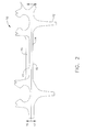
- Thermal barrier 20 as shown in FIG. 2 , can be applied to at least a portion of shaft 14, and in particular to first surface 13 of shaft 14.
- Thermal barrier can comprise any of a variety of materials that comprise the following properties: barrier 20 can be capable of providing a temperature reduction in the metal substrate of at least about 5°C/mm of thermal barrier thickness, and in one embodiment a reduction of at least about 7°C/mm of thermal barrier thickness, as compared to the temperature of the substrate absent the application of thermal barrier 20; barrier 20 can remain affixed to the substrate without decreasing the performance thereof; and, barrier 20 can have a strain tolerance and thermal expansion similar to that of the substrate.
- thermal expansion can be greater than about 8x10 -6 /°C, and in another embodiment, from about 10x10 -6 /°C.
- thermal barrier 20 can have an in-plane modulus of less than 5Msi, and in one embodiment less than 2Msi.
- thermal barrier 20 can comprise a thermal barrier coating (TBC).
- TBC thermal barrier coating
- the TBC may generally comprise any low conductivity material, or combination of materials, currently suitable for use as a TBC, for example, a ceramic such as 7% yttria stabilized zirconia.
- low conductivity indicates that the conductivity of the TBC is less than that of the substrate of the shaft 14.
- a layer of the TBC may be applied to HPC shaft 14 using conventional application methods such as, but not limited to, plasma spray processes, chemical vapor deposition processes, electron beam physical vapor deposition processes, sputtering processes, and the like.
- TBC can provide the desired temperature reduction, adhesion, thermal expansion, and strain tolerance properties set forth previously. Those skilled in the art will understand how to tailor the thickness of the TBC to achieve the previously described properties, as well as how to apply the TBC without damaging the underlying component.
- thermal barrier 20 can comprise a metal heat shield affixed to first surface 13 of shaft 14 on hot flowpath side 16 as shown in FIG. 2 .
- the metal heat shield can be made from any metal, metal alloy, or metal superalloy including those based on nickel, cobalt, iron, or combinations thereof as defined previously, that is capable of withstanding the temperature and stress experienced by shaft 14 during operation.
- suitable materials for the heat shield can include nickel alloys, commonly available under the tradenames HS 188, or HASTX (available from Haynes International, for example).
- the metal heat shield can be attached to shaft 14 by a variety of mechanical or chemical attachment methods. Such placement of the heat shield can help achieve the previously described properties.
- thermal barrier 20 can comprise a thermal blanket. Similar to the TBC, the thermal blanket may comprise any "low conductivity" material wherein the conductivity of the thermal blanket material is less than that of the substrate of the shaft 14. In this embodiment, the thermal blanket can be applied to insulate the substrate of shaft 14 from hot flow path air. In this way, shaft 14 can be kept cooler by backside cooling air. In one embodiment, the thermal blanket can reduce the temperature of shaft 14 by between about 55°C (100°F) and about 83°C (150°F). Those skilled in the art will understand how to tailor the thickness of the thermal blanket to achieve the previously described properties
- thermal barriers described herein for application to HPC shaft can reduce the amount of heat that reaches the shaft. This reduction in heat can result in both reduced thermal stress on the HPC shaft, as well as a lower service operating temperature of the shaft.
- the addition of the thermal barrier can allow the rotating compressor component to be fabricated from materials having a lower temperature capability than used currently, without sacrificing performance.
Landscapes
- Engineering & Computer Science (AREA)
- Mechanical Engineering (AREA)
- General Engineering & Computer Science (AREA)
- Structures Of Non-Positive Displacement Pumps (AREA)
Abstract
Description
- Embodiments described herein generally relate to gas turbine engine compressor components comprising thermal barriers; thermal barrier systems; and methods of using the same. More particularly, embodiments described herein generally relate to gas turbine engine high pressure compressor shafts and thermal barrier systems for use therewith.
- Increasingly stringent demands are being imposed on the efficacy of gas turbine engines employed in the aerospace and power generation industries. This demand is driven by the requirement to reduce the consumption of fossil fuels, and in turn, operating costs. One way to improve turbine efficiency is to increase the operating temperature of the engine. For example, the high pressure compressor currently operates at about 700°C (about 1300°F), with the service operating temperature expected to reach about 788°C (about 1450°F) in the future.
- With increased operating temperatures comes an increased demand on materials, such as those used to make compressor disks. Not only must these materials be able to withstand the higher operating temperatures, but they must also endure increased mechanical stresses, corrosion, erosion, and other severe operating conditions, while continuing to fulfill lifetime requirements expected by the industry.
- One way to address these increased demands is through modification of both the composition and structure of the material used to make the compressor component. More specifically, the composition of the material can be modified to make it capable of operating at the higher temperatures, while the structure of the material, and in particular the grain size, can be increased or decreased depending on whether creep or fatigue, respectively, is the more critical property. However, even with such modifications, there can still be challenges to getting the material to perform properly at increasing temperatures.
- Accordingly, there remains a need for additional measures to protect these materials from the high temperature, high stress environments of the compressor section of a gas turbine engine.
- Embodiments herein generally relate to gas turbine engine compressor disks comprising: a hot flowpath side; a shaft having a first surface positioned in the hot flowpath side; and a thermal barrier applied to at least the first surface of the shaft wherein the thermal barrier is operable to maintain the temperature of the shaft below about 700°C (1300°F) when the hot flowpath side experiences a service operating temperature of from about 700°C (1300°F) to about 788°C (1450°F).
- Embodiments herein also generally relate to thermal barrier systems for a hot flowpath side of a gas turbine engine compressor shaft comprising: a thermal barrier selected from the group consisting of thermal barrier coatings, metal heat shields, and thermal blankets applied to at least a first surface of the compressor shaft wherein the thermal barrier is operable to maintain the temperature of the shaft below about 700°C (1300°F) when the hot flowpath side experiences a service operating temperature of from about 700°C (1300°F) to about 788°C (1450°F).
- Embodiment herein also generally relate to methods for reducing service temperature of operation of a gas turbine engine compressor shaft comprising: providing a compressor shaft having a first surface in a hot flowpath side and a second surface in a cool cavity side; applying a thermal barrier to at least the first surface of the compressor shaft wherein the thermal barrier is operable to maintain the temperature of the shaft below about 700°C (1300°F) when the hot flowpath side experiences a service operating temperature of from about 700°C (1300°F) to about 788°C (1450°F).
- These and other features, aspects and advantages will become evident to those skilled in the art from the following disclosure.
- While the specification concludes with claims particularly pointing out and distinctly claiming the invention, it is believed that the embodiments set forth herein will be better understood from the following description in conjunction with the accompanying figures, in which like reference numerals identify like elements.
-
FIG. 1 is a schematic representation of one embodiment of a high pressure compressor disk in accordance with the description herein; and -
FIG. 2 is an enlarged representation of the compressor disk ofFIG. 1 having a thermal barrier applied in accordance with the description herein. - Embodiments described herein generally relate to gas turbine engine compressor components comprising thermal barriers; thermal barrier systems; and methods of using the same. More particularly, embodiments described herein generally relate to gas turbine engine high pressure compressor shafts and thermal barrier systems for use therewith.
- For purposes of the description herein, the turbine engine compressor component may generally be of any type, however, in one embodiment, the component may be a rotating compressor component, or portion thereof, that experiences a service operating temperature of from about 537°C (about 1000°F) to about 788°C (about 1450°F), and in one embodiment from about 700°C (about 1300°F) to about 788°C (about 1450°F). One example of a rotating compressor component that may benefit from the methods and systems described herein can include, but should not be limited to, compressor disks. While the entire disk may be protected, it may be more advantageous and cost effective to protect a selected portion of the disk, for example, the HPC shaft, as described herein below.
- Referring to
FIG. 1 , a representative embodiment of a turbineengine compressor component 10 is provided. As described previously,compressor component 10 may be of any operable type, such as adisk 12. As shown inFIG. 1 compressor disk 12 may have ashaft 14.Shaft 14 can comprise afirst surface 13 located in thehot flowpath side 16 ofcompressor disk 12, and asecond surface 15, located in thecool cavity side 17 ofcompressor disk 12. During operation, the temperature difference between thehot flowpath side 16 and thecool cavity side 17 can be from about 230°C to about 430°C (about 500°F to about 700°F). During operation, and absent a thermal barrier as set forth herein below, hot air fromhot flowpath side 16 can heat theentire shaft 14, including bothfirst surface 13 andsecond surface 15, to temperatures upwards of 700°C (about 1300°F). Therefore, it may be advantageous to utilize the thermal barriers herein to protect theentire shaft 14, or alternately, thefirst surface 13 thereof. Using a thermal barrier to protectfirst surface 13 ofshaft 14 can help to maintain the temperature ofshaft 14 at a temperature of about 700°C (about 1300°F) even though the service operating temperature of thehot flowpath side 16 ofcompressor disk 12 can reach up to about 788°C (about 1450°F). - Referring to
FIG. 2 ,compressor shaft 14 can comprise any of a variety of polycrystalline substrates such as metals, metal alloys, or metal superalloys, including those based on nickel, cobalt, iron, or combinations thereof. In one embodiment,shaft 14 may comprise a nickel-based superalloy. As used herein throughout, "based" indicates that the metal substrate comprises a greater percentage of the listed element(s) than any other element. For example, a nickel-based superalloy comprises more nickel than any other element. By way of example and not limitation, one nickel-based superalloy that may be used herein is Rene®88 (General Electric Co.) which is generally comprised, by weight, of about 13% cobalt, about 16% chromium, about 4% molybdenum, about 3.7% titanium, about 2.1% aluminum, about 4% tungsten, about 0.70% niobium, about 0.015% boron, about 0.03% zirconium, and about 0.03% carbon, with the balance nickel and minor impurities. -
Thermal barrier 20, as shown inFIG. 2 , can be applied to at least a portion ofshaft 14, and in particular tofirst surface 13 ofshaft 14. Thermal barrier can comprise any of a variety of materials that comprise the following properties:barrier 20 can be capable of providing a temperature reduction in the metal substrate of at least about 5°C/mm of thermal barrier thickness, and in one embodiment a reduction of at least about 7°C/mm of thermal barrier thickness, as compared to the temperature of the substrate absent the application ofthermal barrier 20;barrier 20 can remain affixed to the substrate without decreasing the performance thereof; and,barrier 20 can have a strain tolerance and thermal expansion similar to that of the substrate. Specifically, in one embodiment, thermal expansion can be greater than about 8x10⁻⁶/°C, and in another embodiment, from about 10x10-6/°C. To accommodate the strain from the centrifugal loading,thermal barrier 20 can have an in-plane modulus of less than 5Msi, and in one embodiment less than 2Msi. Some examples of suitablethermal barriers 20 are set forth below. - In one embodiment,
thermal barrier 20 can comprise a thermal barrier coating (TBC). The TBC may generally comprise any low conductivity material, or combination of materials, currently suitable for use as a TBC, for example, a ceramic such as 7% yttria stabilized zirconia. As used herein, "low conductivity" indicates that the conductivity of the TBC is less than that of the substrate of theshaft 14. A layer of the TBC may be applied toHPC shaft 14 using conventional application methods such as, but not limited to, plasma spray processes, chemical vapor deposition processes, electron beam physical vapor deposition processes, sputtering processes, and the like. TBC can provide the desired temperature reduction, adhesion, thermal expansion, and strain tolerance properties set forth previously. Those skilled in the art will understand how to tailor the thickness of the TBC to achieve the previously described properties, as well as how to apply the TBC without damaging the underlying component. - In another embodiment,
thermal barrier 20 can comprise a metal heat shield affixed tofirst surface 13 ofshaft 14 onhot flowpath side 16 as shown inFIG. 2 . Similar to the compressor component, the metal heat shield can be made from any metal, metal alloy, or metal superalloy including those based on nickel, cobalt, iron, or combinations thereof as defined previously, that is capable of withstanding the temperature and stress experienced byshaft 14 during operation. Some examples of suitable materials for the heat shield can include nickel alloys, commonly available under the tradenames HS 188, or HASTX (available from Haynes International, for example). The metal heat shield can be attached toshaft 14 by a variety of mechanical or chemical attachment methods. Such placement of the heat shield can help achieve the previously described properties. - In yet another embodiment,
thermal barrier 20 can comprise a thermal blanket. Similar to the TBC, the thermal blanket may comprise any "low conductivity" material wherein the conductivity of the thermal blanket material is less than that of the substrate of theshaft 14. In this embodiment, the thermal blanket can be applied to insulate the substrate ofshaft 14 from hot flow path air. In this way,shaft 14 can be kept cooler by backside cooling air. In one embodiment, the thermal blanket can reduce the temperature ofshaft 14 by between about 55°C (100°F) and about 83°C (150°F). Those skilled in the art will understand how to tailor the thickness of the thermal blanket to achieve the previously described properties - The thermal barriers described herein for application to HPC shaft can reduce the amount of heat that reaches the shaft. This reduction in heat can result in both reduced thermal stress on the HPC shaft, as well as a lower service operating temperature of the shaft. The addition of the thermal barrier can allow the rotating compressor component to be fabricated from materials having a lower temperature capability than used currently, without sacrificing performance.
- This written description uses examples to disclose the invention, including the best mode, and also to enable any person skilled in the art to make and use the invention. The patentable scope of the invention is defined by the claims, and may include other examples that occur to those skilled in the art. Such other examples are intended to be within the scope of the claims if they have structural elements that do not differ from the literal language of the claims, or if they include equivalent structural elements with insubstantial differences from the literal language of the claims.
Claims (15)
- A gas turbine engine compressor disk (10, 12) comprising:a hot flowpath side (16);a shaft (14) having a first surface (13) positioned in the hot flowpath side (16);anda thermal barrier (20) applied to at least the first surface (13) of the shaft (14)wherein the thermal barrier is operable to maintain the temperature of the shaft below about 700°C (1300°F) when the hot flowpath side experiences a service operating temperature of from about 700°C (1300°F) to about 788°C (1450°F).
- A disk (10, 12) according to claim 1 comprising a polycrystalline substrate selected from the group consisting of metals, metal alloys, and metal superalloys based on nickel, cobalt, iron, and combinations thereof.
- A disk (10, 12) according to any of claims 1 or 2 wherein the thermal barrier (20) comprises a thermal expansion of greater than about 8x10⁻⁶/°C.
- A disk (10, 12) according to any of claims 1, 2 or 3 wherein the thermal barrier (20) comprises an in-plane modulus of less than 5Msi.
- A disk (10, 12) according to any of claims 1, 2, 3 or 4 wherein the thermal barrier (20) is capable of providing a reduction in the service operating temperature of the shaft of at least about 5°C/mm of thermal barrier.
- A disk (10, 12) according to any of claims 1, 2, 3, 4 or 5 comprising a thermal barrier (20) selected from the group consisting of thermal barrier coatings, metal heat shields, and thermal blankets.
- A disk (10, 12) according to claim 6 wherein the thermal barrier coating comprises yttria stabilized zirconia.
- A disk (10, 12) according to claim 6 wherein the metal heat shield comprises a material selected from the group consisting of metals, metal alloys, and metal superalloys based on nickel, cobalt, iron, and combinations thereof.
- A disk (10, 12) according to claim 6 wherein the thermal blanket comprises a low conductivity material.
- A method for reducing service temperature of operation of a gas turbine engine compressor shaft comprising:providing a compressor shaft having a first surface in a hot flowpath side and a second surface in a cool cavity side; andapplying a thermal barrier to at least the first surface of the compressor shaftwherein the thermal barrier is operable to maintain the temperature of the shaft below about 700°C (1300°F) when the hot flowpath side experiences a service operating temperature of from about 700°C (1300°F) to about 788°C (1450°F).
- The method of claim 10, comprising providing a compressor shaft comprising a polycrystalline substrate selected from the group consisting of metals, metal alloys, and metal superalloys based on nickel, cobalt, iron, and combinations thereof.
- The method of claim 11, comprising applying a thermal barrier capable of providing a reduction in the service operating temperature of the shaft of at least about 5°C/mm of thermal barrier thickness.
- The method of claim 11, comprising applying a thermal barrier having a thermal expansion of greater than about 8x10⁻⁶/°C.
- The method of claim 11, comprising applying a thermal barrier having an in-plane modulus of less than 5Msi.
- The method of claim 14, wherein the thermal barrier is selected from the group consisting of thermal barrier coatings, metal heat shields, and thermal blankets.
Applications Claiming Priority (2)
| Application Number | Priority Date | Filing Date | Title |
|---|---|---|---|
| US34532710P | 2010-05-17 | 2010-05-17 | |
| US12/870,315 US20110280716A1 (en) | 2010-05-17 | 2010-08-27 | Gas turbine engine compressor components comprising thermal barriers, thermal barrier systems, and methods of using the same |
Publications (2)
| Publication Number | Publication Date |
|---|---|
| EP2388434A2 true EP2388434A2 (en) | 2011-11-23 |
| EP2388434A3 EP2388434A3 (en) | 2014-12-24 |
Family
ID=44487201
Family Applications (1)
| Application Number | Title | Priority Date | Filing Date |
|---|---|---|---|
| EP11166226.8A Withdrawn EP2388434A3 (en) | 2010-05-17 | 2011-05-16 | Gas turbine engine compressor components comprising thermal barriers and method of using the same |
Country Status (4)
| Country | Link |
|---|---|
| US (1) | US20110280716A1 (en) |
| EP (1) | EP2388434A3 (en) |
| JP (1) | JP2011241832A (en) |
| CA (1) | CA2739210A1 (en) |
Families Citing this family (2)
| Publication number | Priority date | Publication date | Assignee | Title |
|---|---|---|---|---|
| US8784061B2 (en) * | 2011-01-31 | 2014-07-22 | General Electric Company | Methods and systems for controlling thermal differential in turbine systems |
| US9869183B2 (en) | 2014-08-01 | 2018-01-16 | United Technologies Corporation | Thermal barrier coating inside cooling channels |
Family Cites Families (13)
| Publication number | Priority date | Publication date | Assignee | Title |
|---|---|---|---|---|
| US3204406A (en) * | 1960-04-04 | 1965-09-07 | Ford Motor Co | Cooling system for a re-expansion gas turbine engine |
| US4457948A (en) * | 1982-07-26 | 1984-07-03 | United Technologies Corporation | Quench-cracked ceramic thermal barrier coatings |
| US5271711A (en) * | 1992-05-11 | 1993-12-21 | General Electric Company | Compressor bore cooling manifold |
| US6586115B2 (en) * | 2001-04-12 | 2003-07-01 | General Electric Company | Yttria-stabilized zirconia with reduced thermal conductivity |
| DE10356586A1 (en) * | 2003-12-04 | 2005-07-07 | Alstom Technology Ltd | compressor rotor |
| DE102004025049A1 (en) * | 2004-05-18 | 2005-12-15 | Forschungszentrum Jülich GmbH | turbocharger |
| US7666515B2 (en) * | 2005-03-31 | 2010-02-23 | General Electric Company | Turbine component other than airfoil having ceramic corrosion resistant coating and methods for making same |
| US7416788B2 (en) * | 2005-06-30 | 2008-08-26 | Honeywell International Inc. | Thermal barrier coating resistant to penetration by environmental contaminants |
| US7584582B1 (en) * | 2006-02-14 | 2009-09-08 | Physical Systems, Inc. | Adhesive bonded attachment assembly for an insulation blanket |
| US7955694B2 (en) * | 2006-06-21 | 2011-06-07 | General Electric Company | Strain tolerant coating for environmental protection |
| JP4826417B2 (en) * | 2006-09-29 | 2011-11-30 | 株式会社ジェイテクト | Supercharger |
| DE102008029528A1 (en) * | 2008-06-21 | 2009-12-24 | Mtu Aero Engines Gmbh | Gas i.e. cooling air, guiding device for use in gas turbine of aircraft engine, has two guiding elements provided at two adjacent rotor disks and dimensioned such that pre-determined gap is formed between guiding elements |
| US20110048017A1 (en) * | 2009-08-27 | 2011-03-03 | General Electric Company | Method of depositing protective coatings on turbine combustion components |
-
2010
- 2010-08-27 US US12/870,315 patent/US20110280716A1/en not_active Abandoned
-
2011
- 2011-05-05 CA CA2739210A patent/CA2739210A1/en not_active Abandoned
- 2011-05-13 JP JP2011107722A patent/JP2011241832A/en not_active Withdrawn
- 2011-05-16 EP EP11166226.8A patent/EP2388434A3/en not_active Withdrawn
Non-Patent Citations (1)
| Title |
|---|
| None |
Also Published As
| Publication number | Publication date |
|---|---|
| CA2739210A1 (en) | 2011-11-17 |
| EP2388434A3 (en) | 2014-12-24 |
| US20110280716A1 (en) | 2011-11-17 |
| JP2011241832A (en) | 2011-12-01 |
Similar Documents
| Publication | Publication Date | Title |
|---|---|---|
| US7510370B2 (en) | Turbine blade tip and shroud clearance control coating system | |
| EP1953252B1 (en) | Alloy compositions of the MCrAlY type and articles comprising the same | |
| CN103160711B (en) | Nickel-cobalt-based alloy and bond coat and bond coated articles incorporating the same | |
| US7364801B1 (en) | Turbine component protected with environmental coating | |
| US7758968B2 (en) | Component with thermal barrier coating and erosion-resistant layer | |
| US8722202B2 (en) | Method and system for enhancing heat transfer of turbine engine components | |
| US6720088B2 (en) | Materials for protection of substrates at high temperature, articles made therefrom, and method for protecting substrates | |
| US20170218768A1 (en) | Blade of a turbomachine having blade root thermal insulation | |
| CN102301019A (en) | Alloy, protective layer and component | |
| US11555419B2 (en) | Cost effective manufacturing method for GSAC incorporating a stamped preform | |
| US11492692B2 (en) | Thermal barrier coating with high corrosion resistance | |
| EP2388434A2 (en) | Gas turbine engine compressor components comprising thermal barriers and method of using the same | |
| EP2236770B1 (en) | Gas turbine engine article having columnar microstructure | |
| EP1832669A1 (en) | Bond coat process for thermal barrier coating. | |
| CN101130291B (en) | Component with a coating system | |
| US7208232B1 (en) | Structural environmentally-protective coating | |
| US20050031482A1 (en) | Alloys for high temperature applications, articles made therefrom, and method for repair of articles | |
| US8163401B2 (en) | Component having a coating system | |
| Teratani et al. | Reaction diffusion behavior of thermally sprayed MCrAlY coatings on Ni-Based super alloys | |
| EP1457579B1 (en) | Materials for protection of superalloy substrates at high temperature, articles made therefrom, and method for protecting substrates |
Legal Events
| Date | Code | Title | Description |
|---|---|---|---|
| AK | Designated contracting states |
Kind code of ref document: A2 Designated state(s): AL AT BE BG CH CY CZ DE DK EE ES FI FR GB GR HR HU IE IS IT LI LT LU LV MC MK MT NL NO PL PT RO RS SE SI SK SM TR |
|
| AX | Request for extension of the european patent |
Extension state: BA ME |
|
| PUAI | Public reference made under article 153(3) epc to a published international application that has entered the european phase |
Free format text: ORIGINAL CODE: 0009012 |
|
| PUAL | Search report despatched |
Free format text: ORIGINAL CODE: 0009013 |
|
| AK | Designated contracting states |
Kind code of ref document: A3 Designated state(s): AL AT BE BG CH CY CZ DE DK EE ES FI FR GB GR HR HU IE IS IT LI LT LU LV MC MK MT NL NO PL PT RO RS SE SI SK SM TR |
|
| AX | Request for extension of the european patent |
Extension state: BA ME |
|
| RIC1 | Information provided on ipc code assigned before grant |
Ipc: F01D 5/06 20060101AFI20141114BHEP |
|
| STAA | Information on the status of an ep patent application or granted ep patent |
Free format text: STATUS: THE APPLICATION IS DEEMED TO BE WITHDRAWN |
|
| 18D | Application deemed to be withdrawn |
Effective date: 20141202 |