EP2388143A1 - Droplet detecting device and inkjet printer - Google Patents
Droplet detecting device and inkjet printer Download PDFInfo
- Publication number
- EP2388143A1 EP2388143A1 EP10731185A EP10731185A EP2388143A1 EP 2388143 A1 EP2388143 A1 EP 2388143A1 EP 10731185 A EP10731185 A EP 10731185A EP 10731185 A EP10731185 A EP 10731185A EP 2388143 A1 EP2388143 A1 EP 2388143A1
- Authority
- EP
- European Patent Office
- Prior art keywords
- inkjet printer
- unit
- fastening
- light
- detecting device
- Prior art date
- Legal status (The legal status is an assumption and is not a legal conclusion. Google has not performed a legal analysis and makes no representation as to the accuracy of the status listed.)
- Withdrawn
Links
- 239000007788 liquid Substances 0.000 claims abstract description 12
- 238000001514 detection method Methods 0.000 claims description 35
- 230000003287 optical effect Effects 0.000 description 25
- 238000010586 diagram Methods 0.000 description 4
- 238000000034 method Methods 0.000 description 4
- 238000012423 maintenance Methods 0.000 description 3
- 230000005856 abnormality Effects 0.000 description 2
- 230000000694 effects Effects 0.000 description 2
- 238000005452 bending Methods 0.000 description 1
- 238000004512 die casting Methods 0.000 description 1
- 238000007599 discharging Methods 0.000 description 1
- 239000002184 metal Substances 0.000 description 1
- 238000000465 moulding Methods 0.000 description 1
- 238000009877 rendering Methods 0.000 description 1
- 239000011347 resin Substances 0.000 description 1
- 229920005989 resin Polymers 0.000 description 1
Images


Classifications
-
- B—PERFORMING OPERATIONS; TRANSPORTING
- B41—PRINTING; LINING MACHINES; TYPEWRITERS; STAMPS
- B41J—TYPEWRITERS; SELECTIVE PRINTING MECHANISMS, i.e. MECHANISMS PRINTING OTHERWISE THAN FROM A FORME; CORRECTION OF TYPOGRAPHICAL ERRORS
- B41J2/00—Typewriters or selective printing mechanisms characterised by the printing or marking process for which they are designed
- B41J2/005—Typewriters or selective printing mechanisms characterised by the printing or marking process for which they are designed characterised by bringing liquid or particles selectively into contact with a printing material
- B41J2/01—Ink jet
- B41J2/07—Ink jet characterised by jet control
- B41J2/125—Sensors, e.g. deflection sensors
-
- B—PERFORMING OPERATIONS; TRANSPORTING
- B41—PRINTING; LINING MACHINES; TYPEWRITERS; STAMPS
- B41J—TYPEWRITERS; SELECTIVE PRINTING MECHANISMS, i.e. MECHANISMS PRINTING OTHERWISE THAN FROM A FORME; CORRECTION OF TYPOGRAPHICAL ERRORS
- B41J2/00—Typewriters or selective printing mechanisms characterised by the printing or marking process for which they are designed
- B41J2/005—Typewriters or selective printing mechanisms characterised by the printing or marking process for which they are designed characterised by bringing liquid or particles selectively into contact with a printing material
- B41J2/01—Ink jet
- B41J2/015—Ink jet characterised by the jet generation process
- B41J2/04—Ink jet characterised by the jet generation process generating single droplets or particles on demand
- B41J2/045—Ink jet characterised by the jet generation process generating single droplets or particles on demand by pressure, e.g. electromechanical transducers
- B41J2/04501—Control methods or devices therefor, e.g. driver circuits, control circuits
- B41J2/04561—Control methods or devices therefor, e.g. driver circuits, control circuits detecting presence or properties of a drop in flight
-
- B—PERFORMING OPERATIONS; TRANSPORTING
- B41—PRINTING; LINING MACHINES; TYPEWRITERS; STAMPS
- B41J—TYPEWRITERS; SELECTIVE PRINTING MECHANISMS, i.e. MECHANISMS PRINTING OTHERWISE THAN FROM A FORME; CORRECTION OF TYPOGRAPHICAL ERRORS
- B41J2/00—Typewriters or selective printing mechanisms characterised by the printing or marking process for which they are designed
- B41J2/005—Typewriters or selective printing mechanisms characterised by the printing or marking process for which they are designed characterised by bringing liquid or particles selectively into contact with a printing material
- B41J2/01—Ink jet
- B41J2/015—Ink jet characterised by the jet generation process
- B41J2/04—Ink jet characterised by the jet generation process generating single droplets or particles on demand
- B41J2/045—Ink jet characterised by the jet generation process generating single droplets or particles on demand by pressure, e.g. electromechanical transducers
- B41J2/04501—Control methods or devices therefor, e.g. driver circuits, control circuits
- B41J2/04586—Control methods or devices therefor, e.g. driver circuits, control circuits controlling heads of a type not covered by groups B41J2/04575 - B41J2/04585, or of an undefined type
Definitions
- the present invention relates to a droplet detecting device and an inkjet printer.
- an inkjet-type recording apparatus that performs optical position adjustment between a light emitting module and a light receiving module with respect to a base member (for example, see Patent Literature 1).
- the light emitting module and the light receiving module are fixed to a casing as the base member by adjusting the optical axes thereof.
- Patent Literature 1 Japanese Patent Publication No. 3509706
- the present invention is contrived in view of the above, and the object thereof is to allow a droplet detecting device, configured to be integrated with a module base by adjusting the optical axes of a light emitting unit and a light receiving unit used as detection modules, to function stably without variations in accuracy in the state of being fixed to a main body (printer).
- the present invention is a droplet detecting device that detects a discharge state of a liquid droplet by receiving a light beam emitted to a flying path of the liquid droplet discharged from a nozzle of an inkjet printer, the droplet detecting device including: a light emitting unit that emits the light beam; a light receiving unit that receives the emitted light beam; and a detection unit that includes a base unit integrally supporting the light emitting unit and the light receiving unit, wherein the base unit includes: at least two positioning units that are engaged with the inkjet printer and determine the fastening position onto the inkjet printer; and a first fastening unit that is fastened to the inkjet printer, and wherein, in the state of being fastened to the inkjet printer, only the positioning units and the first fastening unit are in contact with the inkjet printer.
- the present invention is the droplet detecting device of claim 1, wherein the first fastening unit is arranged at an approximate center of the detection unit, or at a position close to the light receiving unit from the center.
- the present invention is the droplet detecting device of claim 1 or 2, wherein the base unit further includes a second fastening unit that is fastened to the inkjet printer through an elastic member.
- the present invention is the droplet detecting device of claim 1, 2, or 3, wherein the light receiving unit receives scattering light that is generated when the light beam collides with the liquid droplet, and the detection unit detects the discharge state of the liquid droplet based on light intensity of the scattering light.
- the present invention is an inkjet printer in which the droplet detecting device according to any one of claims 1 to 4 is built.
- a droplet detecting device configured so as to be integrated with a module base by adjusting the optical axes of a light emitting unit and a light receiving unit used as detection modules, to function stably without variations in accuracy in the state of being fixed to a main body (printer).
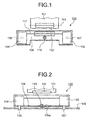
- FIG. 1 is a plan view illustrating the configuration of a droplet detecting device according to this embodiment
- FIG. 2 is a side view of FIG. 1.
- FIGS. 1 and 2 illustrate an example of the configuration of an inkjet printer in which an ink detecting module 100 is incorporated as a droplet detecting device.
- the inkjet printer includes a carriage 101, a recording head 102, a nozzle row 103, an ink detecting module 100, a mounting base 109, and a fastening member 110 including a screw and the like.
- the ink detecting module 100 detects the discharge of liquid droplets by using a light emitting element and a light receiving element.
- the ink detecting module 100 includes a light emitting unit 104 having the light emitting element such as a laser diode, a light receiving unit 105 having the light receiving element such as a photodiode, and a module base 108 supporting the light emitting unit 104 and the light receiving unit 105.
- a module base 108 positioning pins 106 and 107 are formed in the module base 108.
- the positioning pins 106 and 107 are pins that are used for determining the positions of the light emitting unit 104 side and the light receiving unit 105 side.
- a detection beam 111 is emitted from the light emitting unit 104 toward the light receiving unit 105.
- the mounting base 109 is a base, on which the ink detecting module 100 is mounted, located on the inkjet printer main body side.
- the mounting base 109 includes a mounting face 109a having a convex face that gives a predetermined gap between the mounting base 109 and the ink detecting module 100 for screw fastening.
- the light emitting unit 104 and the light receiving unit 105 are integrated with the module base 108 by being adjusted of the optical axes with respect to the positioning pins 106 and 107. Then, the module base 108 is arranged at a portion corresponding to the positioning pins 106 and 107 of the mounting base 109 and then is screw-fastened with a fastening member 110 to the mounting face 109a at one position.
- the optical axis of the detection beam 111 is adjusted with respect to the positioning pins 106 and 107.
- the light emitting unit 104 encases the light emitting element and a driving circuit thereof.
- the light receiving unit 105 encases the light receiving element and a detection circuit thereof.
- the module base 108 needs to have rigidity, taking deformation due to assembly or the like and the misalignment of the optical axis due to distortion into consideration.
- the mounting of the light emitting unit 104 there is likelihood that distortion occurs when the light emitting unit is mounted on the module base 108, distortion occurs when the optical axis is adjusted, distortion occurs when it is mounted on the main body, and the like.
- the shape is enlarged. Accordingly, when a tradeoff with the cost is considered, a chassis structure acquired by bending a metal plate or the like is preferable.
- the detection beam 111 of a detection area that is located between the light emitting unit 104 and the light receiving unit 105 is positioned through adjustment of the optical axis, which is performed in advance, with respect to the positioning pins 106 and 107 of the module base 108.
- the module base 108 is fastened to the mounting base 109 of the main body with the fastening member 110 that is disposed at an approximate center position of the ink detecting module 100.
- the adjustment of the optical axis of the ink detecting module 100 is adjusted through a similar fixing structure.
- the fastening unit need to have a sufficient gap so as not to interfere with the ink detecting module 100.
- other fastening units are arranged so as to protect the ink detecting module 100 from an unpredicted external force applied to the ink detecting module 100, it is necessary to form a gap so as to prevent the interference by using a shoulder screw or the like.
- the detection beam 111 and the nozzle row 103 are parallel to each other.
- the status of ink discharging can be checked by moving the carriage 101 so as to allow the nozzle row 103 and the detection beam 111 to match with each other and to allow ink from the nozzle row 103 to sequentially collide with the detection beam 111.
- FIG. 3 is an explanatory diagram illustrating the configuration of the light emitting unit 104 and the light receiving unit 105 and illustrating an example in which the fastening member 110 is disposed at one position on the light receiving unit 105 side.
- the light emitting unit 104 includes an LD block 201, a laser 202, a light emitting point 203, and a collimate lens 204.
- the light receiving unit 105 includes a PD block 205, a light receiving surface 206, and a reflection surface 207.
- the detection beam 111 which is diffused light whose light emitting point is the light emitting point 203 of the laser 202, is formed as an approximately parallel beam through the collimate lens 204.
- the adjustment of the optical axis and the focus detection are performed in such a manner that the beam waist of the detection beam 111 is positioned on the reflection surface 207 of the PD block 205.
- treatment of stray light is performed by guiding the beam reflected from the reflection surface 207 into the inside of the PD block 205.
- the light receiving surface 206 is light-shielded by the end surface of the reflection surface 207, and through this configuration, the scattering light, generated when an ink droplet collides with the beam, can be detected.
- the output of scattering light from all the nozzle rows can be stably detected when the diameter of the beam on the reflection surface 207 is about 0.1 mm, and a distance between the center and the end surface is 0.4 mm. Accordingly, this state needs to be maintained also in the state of being built in the main body.
- the task of this is how to suppress the distortion occurring at the time of mounting, in a case where the above-described module base 108 has the metal-plate chassis structure described above, and the fastening position thereof becomes important.
- the fastening member 110 is disposed at one position on the light receiving unit 105 side.
- the light receiving surface 206 is influenced as inclination ⁇ .
- a distance Xa up to the fastening unit is short, and thus the amount of the position misalignment is such an extent as not to influence the detection capability.
- the light emitting unit is separated therefrom by a distance Xb, the effect of the distortion on the light emitting unit 104 is not much.
- FIG. 4 is an explanatory diagram illustrating the configuration of the light emitting unit 104 and the light receiving unit 105 and illustrating an example in which the fastening member 110 is disposed at one position on the light emitting unit 104 side.
- the inclination of the light emitting point 203 is ⁇
- the detection beam 111 also inclines by the inclination ⁇ .
- the detection beam 111 enters up to the light receiving surface 206 due to the amount ⁇ of inclination of the beam, rendering the scattering light undetectable.
- a fastening arrangement is more effective in an arrangement where the fastening position gets closer to the light receiving unit 105 side shown FIG. 3 than in an arrangement where a fastening position is near the center as shown FIG. 1 . Because the configuration does not likely to give the influence of the distortion to both side of the light emitting unit 104 and the light receiving unit 105 disposed on both sides.
- FIG. 3 a case is considered in which the detection range is long and there is a problem in the stability of the maintenance of the fastening due to the weight balance of the ink detecting module 100 or the like.
- a configuration example addressing such as case is illustrated in FIGS. 5 and 6 .
- the stability of the maintenance can be achieved while suppressing the distortion due to the fastening to be minimal.
- all the fastening units may be fastened through buffer members.
- the light emitting unit 104 and the light receiving unit 105 are integrated with the module base 108 and the optical axes thereof are adjustted with respect to the positioning pins 106 and 107. Then, the module base 108 is disposed in portions of the mounting base 109 that correspond to the positioning pins 106 and 107 and thereafter is configured so as to be screw-fastened at one position on the mounting face 109a by the fastening member 110. Accordingly, the distortion of the module base 108 at the time of fastening can be reduced to be minimal.
- the influence of the distortion caused by the fastening of the light emitting unit 104 on the light emitting point 203 can be reduced; and the occurrence of the deviation of optical axes in the state where the optical axes have been adjusted in the detection state while the module base being mounted on the main body can be reduced, whereby it is possible to improve the assembly capability and the stability of the detection capability and to provide a low-cost base fastening configuration.
- the stability of the detection can be maintained even when the detection length is long, and accordingly, a long printing head can become also applicable.
- the deviation of the optical axes gives high influence over the detection capability.
- a technique of this embodiment that is capable of reducing the distortion of the module base 108 at the time of fastening to be minimal, it is possible to improve the assembly capability and the stability of the detection capability, and to provide a low-cost base structure.
- the droplet detecting device for example, the configuration of FIG. 1 or 5
- this embodiment by mounting the droplet detecting device (for example, the configuration of FIG. 1 or 5 ) represented by this embodiment into an inkjet printer, it is possible to provide a low-cost inkjet printer having stable rinting capability.
- a droplet detecting device and an inkjet printer according to the present invention are useful for a droplet detecting device and an inkjet printer that detect the discharge of liquid droplets from a nozzle and, particularly, are suitable for a device or a system in which a light emitting device and a light receiving device are integrally mounted on a main body through adjustment of the optical axes thereof.
Landscapes
- Ink Jet (AREA)
Abstract
Provided is an ink detecting module (100) that detects the discharge state of a liquid droplet by receiving a light beam emitted to a flying path of the liquid droplet discharged from a nozzle row (103) of an inkjet printer, the ink detecting module including: a light emitting unit (104) that emits a light beam; a light receiving unit (105) that receives the emitted light beam; and a module base (108) that integrally supports the light emitting unit (104) and the light receiving unit (105), the module base (108) including: positioning pins (106, 107) that are engaged with the inkjet printer and determine the fastening position in the inkjet printer; and a fastening unit that is fastened to the inkjet printer, in which, in the state of being fastened to the inkjet printer, only the positioning pins (106, 107) and the fastening unit are in contact with the inkjet printer.
Description
- The present invention relates to a droplet detecting device and an inkjet printer.
- Conventionally, there is disclosed an inkjet-type recording apparatus that performs optical position adjustment between a light emitting module and a light receiving module with respect to a base member (for example, see Patent Literature 1). In this inkjet-type recording apparatus, the light emitting module and the light receiving module are fixed to a casing as the base member by adjusting the optical axes thereof.
- Patent Literature 1: Japanese Patent Publication No.
3509706 - However, in regard to the conventional inkjet-type recording apparatuses described as above, disclosed is a technique of fixing the light emitting module and the light receiving module to the casing as the base member by adjusting the optical axes thereof. However, there is no consideration of maintenance of the accuracy, the stability, and the like in the optical axis adjustment when the modules are mounted in the main body (printer) after the adjustment. Accordingly, there is a problem in that the accuracy changes in the state in which a droplet detecting device configured to be integrated with a module base by adjusting the optical axes thereof is fixed to the main body (printer), and the function of the optical axis adjustment is not stable.
- The present invention is contrived in view of the above, and the object thereof is to allow a droplet detecting device, configured to be integrated with a module base by adjusting the optical axes of a light emitting unit and a light receiving unit used as detection modules, to function stably without variations in accuracy in the state of being fixed to a main body (printer).
- To solve the problem described above and to achieve the object, the present invention according to claim 1 is a droplet detecting device that detects a discharge state of a liquid droplet by receiving a light beam emitted to a flying path of the liquid droplet discharged from a nozzle of an inkjet printer, the droplet detecting device including: a light emitting unit that emits the light beam; a light receiving unit that receives the emitted light beam; and a detection unit that includes a base unit integrally supporting the light emitting unit and the light receiving unit, wherein the base unit includes: at least two positioning units that are engaged with the inkjet printer and determine the fastening position onto the inkjet printer; and a first fastening unit that is fastened to the inkjet printer, and wherein, in the state of being fastened to the inkjet printer, only the positioning units and the first fastening unit are in contact with the inkjet printer.
- The present invention is the droplet detecting device of claim 1, wherein the first fastening unit is arranged at an approximate center of the detection unit, or at a position close to the light receiving unit from the center.
- The present invention is the droplet detecting device of claim 1 or 2, wherein the base unit further includes a second fastening unit that is fastened to the inkjet printer through an elastic member.
- The present invention is the droplet detecting device of claim 1, 2, or 3, wherein the light receiving unit receives scattering light that is generated when the light beam collides with the liquid droplet, and the detection unit detects the discharge state of the liquid droplet based on light intensity of the scattering light.
- The present invention is an inkjet printer in which the droplet detecting device according to any one of claims 1 to 4 is built.
- According to the present invention, obtainable is an advantage of allowing a droplet detecting device, configured so as to be integrated with a module base by adjusting the optical axes of a light emitting unit and a light receiving unit used as detection modules, to function stably without variations in accuracy in the state of being fixed to a main body (printer).
-
-
FIG. 1 is a plan view illustrating the configuration of a droplet detecting device according to this embodiment. -
FIG. 2 is a side view illustrating the configuration of the droplet detecting device ofFIG. 1 . -
FIG. 3 is an explanatory diagram illustrating the configuration of a light emitting unit and a light receiving unit and illustrating an example in which a fastening member is disposed at one position on the light emitting unit side. -
FIG. 4 is an explanatory diagram illustrating the configuration of a light emitting unit and a light receiving unit and illustrating an example in which a fastening member is disposed at one position on the light emitting unit side. -
FIG. 5 is a plan view illustrating a fastening method in which an elastic member is arranged in the configuration ofFIG. 3 . -
FIG. 6 is a side view illustrating a fastening method in which an elastic member is arranged in the configuration ofFIG. 3 . - Hereinafter, preferred embodiments of a droplet detecting device and an inkjet printer according to the present invention will be described in detail with reference to the accompanying drawings.
-
FIG. 1 is a plan view illustrating the configuration of a droplet detecting device according to this embodiment, andFIG. 2 is a side view ofFIG. 1. FIGS. 1 and 2 illustrate an example of the configuration of an inkjet printer in which anink detecting module 100 is incorporated as a droplet detecting device. As shown inFIGS. 1 and 2 , the inkjet printer includes acarriage 101, arecording head 102, anozzle row 103, anink detecting module 100, amounting base 109, and afastening member 110 including a screw and the like. - The
ink detecting module 100 detects the discharge of liquid droplets by using a light emitting element and a light receiving element. Theink detecting module 100 includes alight emitting unit 104 having the light emitting element such as a laser diode, alight receiving unit 105 having the light receiving element such as a photodiode, and amodule base 108 supporting thelight emitting unit 104 and thelight receiving unit 105. In themodule base 108,positioning pins positioning pins light emitting unit 104 side and thelight receiving unit 105 side. Adetection beam 111 is emitted from thelight emitting unit 104 toward thelight receiving unit 105. - The
mounting base 109 is a base, on which theink detecting module 100 is mounted, located on the inkjet printer main body side. Themounting base 109 includes amounting face 109a having a convex face that gives a predetermined gap between themounting base 109 and theink detecting module 100 for screw fastening. - As illustrated in
FIGS. 1 and 2 , thelight emitting unit 104 and thelight receiving unit 105 are integrated with themodule base 108 by being adjusted of the optical axes with respect to thepositioning pins module base 108 is arranged at a portion corresponding to thepositioning pins mounting base 109 and then is screw-fastened with afastening member 110 to themounting face 109a at one position. - As above, by configuring the
light emitting unit 104 and thelight receiving unit 105 so as to be integrated with themodule base 108, the optical axis of thedetection beam 111 is adjusted with respect to thepositioning pins light emitting unit 104 encases the light emitting element and a driving circuit thereof. Thelight receiving unit 105 encases the light receiving element and a detection circuit thereof. - In addition, the
module base 108 needs to have rigidity, taking deformation due to assembly or the like and the misalignment of the optical axis due to distortion into consideration. Particularly, regarding the mounting of thelight emitting unit 104, there is likelihood that distortion occurs when the light emitting unit is mounted on themodule base 108, distortion occurs when the optical axis is adjusted, distortion occurs when it is mounted on the main body, and the like. In order to avoid these problem, there may be considered a configuration of increasing the plate thickness of themodule base 108 or a configuration using die casting or resin molding so as to improve the rigidity of themodule base 108. However, when taking the rigidity into consideration, the shape is enlarged. Accordingly, when a tradeoff with the cost is considered, a chassis structure acquired by bending a metal plate or the like is preferable. - Next, a structure for minimizing the misalignment of the optical axis due to the mounting structure will be described. First, the mounting and the position determining structure of the
ink detecting module 100 will be described. Thedetection beam 111 of a detection area that is located between thelight emitting unit 104 and thelight receiving unit 105 is positioned through adjustment of the optical axis, which is performed in advance, with respect to thepositioning pins module base 108. In consideration of the misalignment of the optical axis attributable to the occurrence of distortion of themodule base 108 that is caused by the bias of the weight balance of theink detecting module 100, themodule base 108 is fastened to themounting base 109 of the main body with thefastening member 110 that is disposed at an approximate center position of theink detecting module 100. As is obvious, it is preferable that the adjustment of the optical axis of theink detecting module 100 is adjusted through a similar fixing structure. - In addition, it is preferable to consider the area and the flatness of the
mounting face 109a of themounting base 109 of the main body for suppressing the occurrence of distortion at the time of the fastening to be minimal. In addition, units other than the fastening unit need to have a sufficient gap so as not to interfere with theink detecting module 100. In a case where other fastening units are arranged so as to protect theink detecting module 100 from an unpredicted external force applied to theink detecting module 100, it is necessary to form a gap so as to prevent the interference by using a shoulder screw or the like. - Through the fastening as above, the
detection beam 111 and thenozzle row 103 are parallel to each other. In addition, the status of ink discharging can be checked by moving thecarriage 101 so as to allow thenozzle row 103 and thedetection beam 111 to match with each other and to allow ink from thenozzle row 103 to sequentially collide with thedetection beam 111. - Next, the detection capability and the like based on the arrangement of the fastening
member 110 in the above-described configuration will be described with reference toFIGS. 3 and 4. FIG. 3 is an explanatory diagram illustrating the configuration of thelight emitting unit 104 and thelight receiving unit 105 and illustrating an example in which thefastening member 110 is disposed at one position on thelight receiving unit 105 side. As illustrated inFIG. 3 , thelight emitting unit 104 includes anLD block 201, alaser 202, alight emitting point 203, and acollimate lens 204. Thelight receiving unit 105 includes aPD block 205, alight receiving surface 206, and areflection surface 207. - As illustrated in
FIG. 3 , thedetection beam 111, which is diffused light whose light emitting point is thelight emitting point 203 of thelaser 202, is formed as an approximately parallel beam through thecollimate lens 204. In this embodiment, in the state in which thedetection beam 111 is detected, the adjustment of the optical axis and the focus detection are performed in such a manner that the beam waist of thedetection beam 111 is positioned on thereflection surface 207 of thePD block 205. Then, treatment of stray light is performed by guiding the beam reflected from thereflection surface 207 into the inside of thePD block 205. Meanwhile, thelight receiving surface 206 is light-shielded by the end surface of thereflection surface 207, and through this configuration, the scattering light, generated when an ink droplet collides with the beam, can be detected. - In such a configuration, for example, the output of scattering light from all the nozzle rows can be stably detected when the diameter of the beam on the
reflection surface 207 is about 0.1 mm, and a distance between the center and the end surface is 0.4 mm. Accordingly, this state needs to be maintained also in the state of being built in the main body. However, the task of this is how to suppress the distortion occurring at the time of mounting, in a case where the above-describedmodule base 108 has the metal-plate chassis structure described above, and the fastening position thereof becomes important. - In
FIG. 3 , thefastening member 110 is disposed at one position on thelight receiving unit 105 side. At this time, in a case where there is an abnormality such that a distortion θ occurs when mounting the module base to the mountingface 109a, thelight receiving surface 206 is influenced as inclination β. However, a distance Xa up to the fastening unit is short, and thus the amount of the position misalignment is such an extent as not to influence the detection capability. In addition, since the light emitting unit is separated therefrom by a distance Xb, the effect of the distortion on thelight emitting unit 104 is not much. -
FIG. 4 is an explanatory diagram illustrating the configuration of thelight emitting unit 104 and thelight receiving unit 105 and illustrating an example in which thefastening member 110 is disposed at one position on thelight emitting unit 104 side. InFIG. 4 , in a case where there is an abnormality such that a distortion θ occurs when mounting the module base onto the mountingface 109a, the inclination of thelight emitting point 203 is β, and thedetection beam 111 also inclines by the inclination β. In addition, at the leading end of thedetection beam 111, since the distance Xb is long, the amount α of beam inclination is created. In this example, thedetection beam 111 enters up to thelight receiving surface 206 due to the amount α of inclination of the beam, rendering the scattering light undetectable. - An approximate calculation of the amount α of inclination of the beam is as below. The distortion of the fastening unit of 0.05 mm is increased up to 1 mm at the light receiving position based on "beam inclination amount α = distortion θ × distance Xb / fastening unit diameter (- = 0.05 × 200/10 = 1)" when the distortion θ of 0.05 mm occurs with the diameter of the fastening unit = ϕ10 mm, and a distance from the
light emitting point 203 to thelight receiving surface 206 Xb = 200 mm. - Accordingly, it can be said that a fastening arrangement is more effective in an arrangement where the fastening position gets closer to the
light receiving unit 105 side shownFIG. 3 than in an arrangement where a fastening position is near the center as shownFIG. 1 . Because the configuration does not likely to give the influence of the distortion to both side of thelight emitting unit 104 and thelight receiving unit 105 disposed on both sides. - However, in the configuration of
FIG. 3 , a case is considered in which the detection range is long and there is a problem in the stability of the maintenance of the fastening due to the weight balance of theink detecting module 100 or the like. A configuration example addressing such as case is illustrated inFIGS. 5 and 6 .
In the configuration as illustrated inFIGS. 5 and 6 , by fastening thefastening member 110 through anelastic member 210 to thelight emitting unit 104 side, the stability of the maintenance can be achieved while suppressing the distortion due to the fastening to be minimal. In addition, all the fastening units may be fastened through buffer members. - As described above, the
light emitting unit 104 and thelight receiving unit 105 are integrated with themodule base 108 and the optical axes thereof are adusted with respect to the positioning pins 106 and 107. Then, themodule base 108 is disposed in portions of the mountingbase 109 that correspond to the positioning pins 106 and 107 and thereafter is configured so as to be screw-fastened at one position on the mountingface 109a by thefastening member 110. Accordingly, the distortion of themodule base 108 at the time of fastening can be reduced to be minimal. In addition, since it is possible to suppress the occurrence of the deviation of the optical axes in the state where the optical axes are adjusted while the module base being mounted on the main body, it is possible to improve the assembly capability and the stability of the detection capability and to provide a low-cost base structure. - In addition, by setting the above-described fastening position to a position near the center of the
ink detecting module 100 or to a position near to thelight receiving unit 105, the influence of the distortion caused by the fastening of thelight emitting unit 104 on thelight emitting point 203 can be reduced; and the occurrence of the deviation of optical axes in the state where the optical axes have been adjusted in the detection state while the module base being mounted on the main body can be reduced, whereby it is possible to improve the assembly capability and the stability of the detection capability and to provide a low-cost base fastening configuration. - In addition, by fastening through the
elastic member 210 located at least at one position in a gap portion between theink detecting module 100 and the mountingbase 109 other than the fastening unit, the stability of the detection can be maintained even when the detection length is long, and accordingly, a long printing head can become also applicable. - In addition, in a configuration where the optical axes of the light emitting device and the light receiving device are offset and where the scattering light is detected thereby, the deviation of the optical axes gives high influence over the detection capability. In the case of such a detection configuration, especially, by employing a technique of this embodiment that is capable of reducing the distortion of the
module base 108 at the time of fastening to be minimal, it is possible to improve the assembly capability and the stability of the detection capability, and to provide a low-cost base structure. In addition, by mounting the droplet detecting device (for example, the configuration ofFIG. 1 or5 ) represented by this embodiment into an inkjet printer, it is possible to provide a low-cost inkjet printer having stable rinting capability. - As described above, a droplet detecting device and an inkjet printer according to the present invention are useful for a droplet detecting device and an inkjet printer that detect the discharge of liquid droplets from a nozzle and, particularly, are suitable for a device or a system in which a light emitting device and a light receiving device are integrally mounted on a main body through adjustment of the optical axes thereof.
-
- 100
- INK DETECTING MODULE
- 101
- CARRIAGE
- 102
- RECORDING HEAD
- 103
- NOZZLE ROW
- 104
- LIGHT EMITTING UNIT
- 105
- LIGHT RECEIVING UNIT
- 106, 107
- POSITIONING PINS
- 108
- MODULE BASE
- 109
- MOUNTING BASE
- 109a
- MOUNTING FACE
- 110
- FASTENING MEMBER
- 111
- DETECTION BEAM
- 210
- ELASTIC MEMBER
Claims (5)
- A droplet detecting device that detects a discharge state of a liquid droplet by receiving a light beam emitted to a flying path of the liquid droplet discharged from a nozzle of an inkjet printer, the droplet detecting device comprising:a light emitting unit that emits the light beam;a light receiving unit that receives the emitted light beam; anda detection unit that includes a base unit integrally supporting the light emitting unit and the light receiving unit,wherein the base unit includes:at least two positioning units that are engaged with the inkjet printer and determine the fastening position onto the inkjet printer; anda first fastening unit that is fastened to the inkjet printer, andwherein, in the state of being fastened to the inkjet printer, only the positioning units and the first fastening unit are in contact with the inkjet printer.
- The droplet detecting device of claim 1,
wherein the first fastening unit is arranged at an approximate center of the detection unit, or at a position close to the light receiving unit from the center. - The droplet detecting device of claim 1 or 2,
wherein the base unit further includes a second fastening unit that is fastened to the inkjet printer through an elastic member. - The droplet detecting device of claim 1, 2, or 3,
wherein the light receiving unit receives scattering light that is generated when the light beam collides with the liquid droplet, and
the detection unit detects the discharge state of the liquid droplet based on light intensity of the scattering light. - An inkjet printer in which the droplet detecting device according to any one of claims 1 to 4 is built.
Applications Claiming Priority (2)
| Application Number | Priority Date | Filing Date | Title |
|---|---|---|---|
| JP2009007822A JP4955713B2 (en) | 2009-01-16 | 2009-01-16 | Droplet detection device and inkjet printer |
| PCT/JP2010/050047 WO2010082516A1 (en) | 2009-01-16 | 2010-01-06 | Droplet detecting device and inkjet printer |
Publications (1)
| Publication Number | Publication Date |
|---|---|
| EP2388143A1 true EP2388143A1 (en) | 2011-11-23 |
Family
ID=42339769
Family Applications (1)
| Application Number | Title | Priority Date | Filing Date |
|---|---|---|---|
| EP10731185A Withdrawn EP2388143A1 (en) | 2009-01-16 | 2010-01-06 | Droplet detecting device and inkjet printer |
Country Status (5)
| Country | Link |
|---|---|
| US (1) | US8485633B2 (en) |
| EP (1) | EP2388143A1 (en) |
| JP (1) | JP4955713B2 (en) |
| CN (1) | CN102196917B (en) |
| WO (1) | WO2010082516A1 (en) |
Families Citing this family (5)
| Publication number | Priority date | Publication date | Assignee | Title |
|---|---|---|---|---|
| JP5652263B2 (en) * | 2011-03-03 | 2015-01-14 | 株式会社リコー | Image forming apparatus and droplet discharge detection method in the image forming apparatus |
| JP5652264B2 (en) | 2011-03-03 | 2015-01-14 | 株式会社リコー | Image forming apparatus and droplet discharge detection method in the image forming apparatus |
| JP6264025B2 (en) * | 2013-12-20 | 2018-01-24 | 株式会社リコー | Droplet discharge state detection device, droplet discharge state detection method, and image forming apparatus |
| DE102015117246A1 (en) * | 2015-10-09 | 2017-04-13 | Vermes Microdispensing GmbH | Optical fiber arrangement for optical drop detection |
| CN110254051B (en) * | 2019-06-24 | 2021-03-23 | Tcl华星光电技术有限公司 | Ink-jetting state detection system and detection method of ink-jetting head |
Family Cites Families (13)
| Publication number | Priority date | Publication date | Assignee | Title |
|---|---|---|---|---|
| JPS55112223U (en) * | 1979-01-31 | 1980-08-07 | ||
| JP3285676B2 (en) * | 1993-08-25 | 2002-05-27 | キヤノン株式会社 | Ink end detecting device and ink end detecting method for ink jet recording apparatus |
| JPH0847087A (en) * | 1994-07-29 | 1996-02-16 | Matsushita Electric Ind Co Ltd | Speaker |
| US6305777B1 (en) * | 1998-08-04 | 2001-10-23 | Sarnoff Corporation | Apparatus and method for measurement of a liquid droplet |
| JP2001063010A (en) * | 1999-08-25 | 2001-03-13 | Canon Inc | Ink detection sensor |
| JP3509706B2 (en) | 2000-06-21 | 2004-03-22 | セイコーエプソン株式会社 | Ink jet recording device |
| US6550885B2 (en) | 2000-01-12 | 2003-04-22 | Seiko Epson Corporation | Ink jet recording device and ink drop jetting inspection method for the ink jet recording device |
| US6641246B2 (en) | 2000-02-23 | 2003-11-04 | Seiko Epson Corporation | Detection of non-operating nozzle by light beam passing through aperture |
| ATE324983T1 (en) | 2000-02-23 | 2006-06-15 | Seiko Epson Corp | DETECTION OF A NON-FUNCTIONING NOZZLE USING A BEAM OF LIGHT THROUGH AN OPENING |
| JP2005007809A (en) * | 2003-06-20 | 2005-01-13 | Canon Finetech Inc | Inkjet recorder |
| JP4474870B2 (en) * | 2003-08-27 | 2010-06-09 | セイコーエプソン株式会社 | Droplet visual recognition method, droplet discharge head inspection device, and droplet discharge device |
| JP4331760B2 (en) | 2007-01-22 | 2009-09-16 | シャープ株式会社 | Droplet discharge head inspection device and droplet discharge device |
| JP5222042B2 (en) * | 2008-06-26 | 2013-06-26 | リコーエレメックス株式会社 | Inkjet recording device |
-
2009
- 2009-01-16 JP JP2009007822A patent/JP4955713B2/en not_active Expired - Fee Related
-
2010
- 2010-01-06 EP EP10731185A patent/EP2388143A1/en not_active Withdrawn
- 2010-01-06 US US13/126,330 patent/US8485633B2/en not_active Expired - Fee Related
- 2010-01-06 WO PCT/JP2010/050047 patent/WO2010082516A1/en not_active Ceased
- 2010-01-06 CN CN201080002989.XA patent/CN102196917B/en not_active Expired - Fee Related
Non-Patent Citations (1)
| Title |
|---|
| See references of WO2010082516A1 * |
Also Published As
| Publication number | Publication date |
|---|---|
| JP4955713B2 (en) | 2012-06-20 |
| US8485633B2 (en) | 2013-07-16 |
| CN102196917B (en) | 2014-04-02 |
| CN102196917A (en) | 2011-09-21 |
| US20110205283A1 (en) | 2011-08-25 |
| JP2010162790A (en) | 2010-07-29 |
| WO2010082516A1 (en) | 2010-07-22 |
Similar Documents
| Publication | Publication Date | Title |
|---|---|---|
| US8485633B2 (en) | Droplet detecting device and inkjet printer | |
| JP4931759B2 (en) | Liquid discharge failure detection device and ink jet recording device | |
| US9193197B2 (en) | Liquid droplet detecting device, inkjet recording device incorporating same, and liquid droplet detection method | |
| EP2065204B1 (en) | Liquid-discharge-failure detecting apparatus, and inkjet recording apparatus | |
| JP7470299B2 (en) | Object detection device, sensing device and moving body | |
| JP6225517B2 (en) | Droplet discharge state detection apparatus and image forming apparatus | |
| EP2714403B1 (en) | Drop detector | |
| EP2138309B1 (en) | Inkjet recording apparatus | |
| US7845752B2 (en) | Liquid-discharge-failure detecting apparatus and inkjet recording apparatus | |
| US20150035929A1 (en) | Optical scanning apparatus and image forming apparatus including the same | |
| US8439476B2 (en) | Method of adjusting optical axis of ink droplet detecting device, method of assembling ink droplet detecting device, and apparatus for adjusting optical axis | |
| US7862141B2 (en) | Liquid-discharge-failure detecting apparatus and inkjet recording apparatus | |
| JP2019048420A (en) | Printing device | |
| JP2007125876A (en) | Pattern forming method and droplet discharge apparatus | |
| JP6500395B2 (en) | Droplet discharge state detection device and image forming apparatus | |
| KR20210038101A (en) | Method and apparatus for monitoring inkjethead | |
| JP5954026B2 (en) | Droplet discharge state detection apparatus and image forming apparatus | |
| US12565051B2 (en) | Printing apparatus for adjusting positional accuracy of sensors | |
| US12552157B2 (en) | Printing apparatus, discharge state detecting apparatus, and discharge state detecting method | |
| JP2006068980A (en) | Inkjet head mounting inspection device | |
| JP2012192552A (en) | Device for detecting state of droplet discharge, head array unit and image forming apparatus | |
| JP2009045912A (en) | Linear sensor mounting structure and printer | |
| JP4396222B2 (en) | Method for detecting inclination of recording head in ink jet recording apparatus, method for adjusting parallelism between nozzle array of recording head and optical axis of droplet detecting means in ink jet recording apparatus, and ink jet recording apparatus | |
| CN118591453A (en) | Systems and methods for optical droplet analysis | |
| JP2012162064A (en) | Recording device and control method |
Legal Events
| Date | Code | Title | Description |
|---|---|---|---|
| PUAI | Public reference made under article 153(3) epc to a published international application that has entered the european phase |
Free format text: ORIGINAL CODE: 0009012 |
|
| 17P | Request for examination filed |
Effective date: 20110420 |
|
| AK | Designated contracting states |
Kind code of ref document: A1 Designated state(s): AT BE BG CH CY CZ DE DK EE ES FI FR GB GR HR HU IE IS IT LI LT LU LV MC MK MT NL NO PL PT RO SE SI SK SM TR |
|
| DAX | Request for extension of the european patent (deleted) | ||
| RAP1 | Party data changed (applicant data changed or rights of an application transferred) |
Owner name: RICOH COMPANY, LTD. |
|
| STAA | Information on the status of an ep patent application or granted ep patent |
Free format text: STATUS: THE APPLICATION IS DEEMED TO BE WITHDRAWN |
|
| 18D | Application deemed to be withdrawn |
Effective date: 20150801 |