EP2387054A2 - Electrical switching apparatus, and levering assembly and position indicator assembly therefor - Google Patents
Electrical switching apparatus, and levering assembly and position indicator assembly therefor Download PDFInfo
- Publication number
- EP2387054A2 EP2387054A2 EP11003865A EP11003865A EP2387054A2 EP 2387054 A2 EP2387054 A2 EP 2387054A2 EP 11003865 A EP11003865 A EP 11003865A EP 11003865 A EP11003865 A EP 11003865A EP 2387054 A2 EP2387054 A2 EP 2387054A2
- Authority
- EP
- European Patent Office
- Prior art keywords
- indicator
- gear
- drive shaft
- teeth
- rack
- Prior art date
- Legal status (The legal status is an assumption and is not a legal conclusion. Google has not performed a legal analysis and makes no representation as to the accuracy of the status listed.)
- Granted
Links
Images





Classifications
-
- H—ELECTRICITY
- H02—GENERATION; CONVERSION OR DISTRIBUTION OF ELECTRIC POWER
- H02B—BOARDS, SUBSTATIONS OR SWITCHING ARRANGEMENTS FOR THE SUPPLY OR DISTRIBUTION OF ELECTRIC POWER
- H02B11/00—Switchgear having carriage withdrawable for isolation
- H02B11/02—Details
- H02B11/10—Indicating electrical condition of gear; Arrangement of test sockets
-
- H—ELECTRICITY
- H02—GENERATION; CONVERSION OR DISTRIBUTION OF ELECTRIC POWER
- H02B—BOARDS, SUBSTATIONS OR SWITCHING ARRANGEMENTS FOR THE SUPPLY OR DISTRIBUTION OF ELECTRIC POWER
- H02B11/00—Switchgear having carriage withdrawable for isolation
- H02B11/12—Switchgear having carriage withdrawable for isolation with isolation by horizontal withdrawal
- H02B11/127—Withdrawal mechanism
Definitions
- the disclosed concept relates generally to electrical switching apparatus and, more particularly, to electrical switching apparatus, such as circuit breakers.
- the disclosed concept also relates to levering assemblies and to position indicator assemblies for circuit breakers.
- Switchgear enclosure either individually or in combination with other switchgear (e.g., without limitation, circuit switching devices and circuit interrupters such as circuit breakers, contactors, motor starters, motor controllers and other load controllers).
- circuit switching devices and circuit interrupters such as circuit breakers, contactors, motor starters, motor controllers and other load controllers.
- Some electrical switching apparatus such as, for example, some medium-voltage and low-voltage circuit breakers, can be relatively large.
- some circuit breakers are commonly coupled to draw-out mechanisms which permit such circuit breakers to be drawn out of the switchgear enclosure. Accordingly, such circuit breakers are commonly known in the art as "draw-out" circuit breakers.
- the circuit breaker may be further supported within a draw-out frame, commonly known in the art as a cassette or chassis.
- the switchgear enclosure generally includes a number of cells, with each cell being structured to receive a corresponding circuit breaker.
- the draw-out mechanism includes, for example, a combination of rails and rollers coupled to one or the other, or both, of the sidewalls of the cell and the sides of the corresponding circuit breaker and/or cassette, which is to be drawn into and out of the cell.
- a levering in assembly (sometimes referred to as a "lev-in” device), which among other components includes a drive screw and drive rack, facilitates levering the circuit breaker into the cassette.
- Draw-out circuit breakers are described in further detail, for example, in commonly assigned U.S. Patent No. 7,019,229 , which is hereby incorporated herein by reference.
- lev-in devices When a draw-out circuit breaker is being levered into a cassette, proper position or travel indication must be displayed. For example, such indication is both required for safety, and used for interlocking of the circuit breaker mechanism and lev-in device.
- Some lev-in devices include a position indicator for this purpose.
- the motion associated with providing the indication is not constant.
- mechanical drive of the position indicator is intermittent, in view of the use of partial gear teeth, cams and/or slots.
- the position indicator assembly provides complete and uninterrupted mechanical indication of the position of the circuit breaker when it is being levered into a corresponding cassette.
- a position indicator assembly for a levering assembly of an electrical switching apparatus.
- the electrical switching apparatus includes a housing.
- the levering assembly comprises a drive shaft and a racking member movably coupled to the housing.
- the drive shaft cooperates with the racking member to facilitate racking of the electrical switching apparatus into and out of a cassette.
- the position indicator assembly comprises: a number of indicator gears structured to cooperate with the drive shaft; an indication rack cooperating with at least one of the number of indicator gears; and an indicator structured to cooperate with the indication rack to provide a visual indication indicative of the position of the electrical switching apparatus with respect to the cassette.
- the drive shaft pivots.
- the indicator gears are structured to move, thereby moving the indication rack and the indicator in order to provide the visual indication.
- the indication rack may be an elongated member comprising a first end and a second end disposed opposite and distal from the first end, and the number of indicator gears may comprise a first indicator gear and a second indicator gear.
- the first indicator gear may be structured to be disposed on the drive shaft, and the second indicator gear may be structured to cooperate with the first indicator gear and the first end of the indication rack.
- the first indicator gear may include a plurality of teeth, and the indication rack may further comprise a plurality of grooves disposed at or about the first end of the indication rack, and a plurality of grooves disposed at or about the second end of the indication rack.
- the second indicator gear may include a first portion having a first diameter and a plurality of teeth, and a second portion having a second diameter and a plurality of teeth, wherein the first diameter is greater than the second diameter.
- the teeth of the first portion may cooperate with the teeth of the first indicator gear.
- the teeth of the second portion may be structured to cooperate with the grooves of the first end of the indication rack to move the indication rack toward and away from the drive shaft.
- the number of indicator gears may further comprise a third indicator gear, wherein the third indicator gear includes a plurality of teeth cooperating with the grooves of the second end of the indication rack.
- the indicator may comprise a plurality of teeth, wherein the teeth of the third indicator gear cooperate with the teeth of the indicator.
- the third indicator gear may pivot, thereby moving the indicator to provide the visual indication indicative of the position of the electrical switching apparatus with respect to the cassette.
- the second indicator gear may be an idler gear
- the third indicator gear may be a reverser gear, wherein the idler gear and the reverser gear are structured to provide a gear reduction in order to reduce the amount the indicator moves for a given corresponding movement of the drive shaft.
- a levering assembly for an electrical switching apparatus.
- the electrical switching apparatus may be structured to be removably disposed in a cassette, and may include a housing.
- the levering assembly comprises: a drive shaft; a racking member movably coupled to the housing, the drive shaft being structured to cooperate with the racking member to rack the electrical switching apparatus into and out of the cassette; and a position indicator assembly comprising: a number of indicator gears cooperating with the drive shaft, an indication rack cooperating with at least one of the number of indicator gears, and an indicator structured to cooperate with the indication rack to provide a visual indication indicative of the position of the electrical switching apparatus with respect to the cassette.
- the drive shaft pivots.
- the indicator gears move, thereby moving the indication rack and the indicator in order to provide the visual indication.
- an electrical switching apparatus comprises: a housing; and a levering assembly comprising: a drive shaft, a racking member movably coupled to the housing, the drive shaft being structured to cooperate with the racking member to rack the electrical switching apparatus into and out of a cassette, and a position indicator assembly comprising: a number of indicator gears cooperating with the drive shaft, an indication rack cooperating with at least one of the number of indicator gears, and an indicator structured to cooperate with the indication rack to provide a visual indication indicative of the position of the electrical switching apparatus with respect to the cassette.
- the drive shaft pivots.
- the indicator gears move, thereby moving the indication rack and the indicator in order to provide the visual indication.
- number shall mean one or an integer greater than one (i. e., a plurality).
- FIG. 1 shows a non-limiting example of a an electrical switching apparatus, such as a circuit breaker 2, with which a levering assembly 100 and position indicator assembly 200 therefor, in accordance with the disclosed concept, can be employed.
- the circuit breaker 2 includes a housing 4, separable contacts 6 (shown in simplified form) enclosed by the housing 4, and an operating mechanism 8 (shown in simplified form) for opening and closing the separable contacts 6.
- the circuit breaker housing 4 includes first and second opposing sides 10,12 and a cover 14 extending therebetween.
- the cover 14 includes a window 16 through which an indicator 210 and a visual indication 212 of the position indicator assembly 200 can be seen.
- a visual indication in the form of a "connect" label 212 is visible in the window 16.
- the circuit breaker 2 is removably disposed in a cassette 300. That is, the circuit breaker 2 can be racked or levered into and out of the cassette 300 by way of the levering assembly 100.
- the levering assembly 100 includes a drive shaft 112, and at least one racking member 114 movably coupled to the circuit breaker housing 4 ( Figure 1 ).
- One racking member 114 is shown and described herein, for economy of disclosure and simplicity of illustration. It will be appreciated, however, that a second racking member (not shown), for example and without limitation which is disposed opposite and distal from racking member 114, could be employed without departing from the scope of the disclosed concept.
- the drive shaft 112 cooperates with the racking member 114 to facilitate racking of the circuit breaker 2 into and out of the cassette 300.
- the levering assembly 100 further includes a mounting member 102 to which the aforementioned drive shaft 112 is pivotably coupled.
- the mounting member 102 includes first and second opposing sides 104,106 and first and second opposing edges 108,110.
- a drive screw 116 which can preferably be accessed through a corresponding opening in the circuit breaker cover 14 ( Figure 1 ), extends from at or about the first side 104 toward the second side 106.
- the levering assembly 100 further includes a drive rack 118, and a drive gear 120.
- the drive gear 120 is preferably disposed on the drive shaft 112 between the first and second ends 122,124 thereof.
- the first end 122 of the example drive shaft 112 extends outwardly from the first edge 108 of the mounting member 102, and the second end 124 extends outwardly from the second edge 110.
- a racking gear 128,130 is disposed on at least one of the ends 122,124.
- a first racking gear 128 is disposed on the first end 122 of the drive shaft 112
- a second racking gear 130 is disposed on the second end 124.
- the drive screw 116 includes a plurality of threads 136, the drive rack 118 includes a plurality of grooves 138, and the drive gear 120 includes a plurality of teeth 140. Therefore, in operation, when the drive screw 116 is pivoted (e.g., without limitation, rotated clockwise or counterclockwise from the perspective of Figure 2 ) the threads 136 of the drive screw 116 cooperate with the grooves 138 8 of the drive rack 118, to move the drive rack 118 with respect to the drive gear 120. When the drive rack 118 moves (e.g., without limitation, toward and away from the drive shaft 112), the grooves 138 of the drive rack 118 cooperate with the teeth 140 of the drive gear 120 to pivot the drive gear 120 and thereby correspondingly pivot the drive shaft 112.
- the position indicator assembly 200 includes a number of indicator gears 202,204,206, which are structured to cooperate with the drive shaft 112.
- An indication rack 208 cooperates with at least one of the indicator gears 202,204,206, as will be described in greater detail hereinbelow.
- an indicator 210 cooperates with the indication rack 208 to provide a visual indication 212,214,216 (e.g., without limitation, the word "connect” 212 ( Figures 1 and 2 ), the word “disconnect” 214 ( Figure 5 ), or the word “test” 116 ( Figure 8 ) displayed at window 16 ( Figure 1 ) of circuit breaker cover 14 ( Figure 1 )), which is indicative of the position of the circuit breaker 2 ( Figure 1 ) with respect to the cassette 300 ( Figure 1 ).
- the drive shaft 112 pivots.
- the indicator gears 202,204,206 three are shown) move, thereby moving the indication rack 208 and the indicator 210 to provide the aforementioned visual indication 212,214,216.
- the indication rack is an elongated member 208, having first and second opposing ends 218,220.
- the position indicator assembly 200 includes three indicator gears 202,204,206, although it will be appreciated that any known or suitable alternative number and/or configuration of indicator gears could be employed.
- a first indicator gear 202 is disposed on the drive shaft 112 proximate the second end 124 thereof.
- a second indicator gear 204 cooperates with the first indicator gear 202, and with the first end 218 of the indication rack 208.
- the first indicator gear 202 includes a plurality of teeth 222
- the indication rack 208 includes a plurality of grooves 224 disposed at or about the first end 218 of the indication rack 208, and a plurality of grooves 226 disposed at or about the second end 220 of the indication rack 208.
- the second indicator gear 204 includes a first portion 228 having a first diameter 230 ( Figure 4 ) and a plurality of teeth 232, and a second portion 234 having a second diameter 236 ( Figure 4 ) and a plurality of teeth 238. As shown in Figure 4 , the first diameter 230 is greater than the second diameter 236.
- first portion 228 is shown in the sectional views of Figures 4 , 7 and 10 , in order to see part of the second portion 234 which would otherwise be hidden.
- the teeth 232 of the first portion 228 of second indicator gear 204 cooperate with the teeth 222 of the first indicator gear 202
- the teeth 238 of the second portion 234 of second indicator gear 204 cooperate with the grooves 224 of the first end 218 of the indication rack 208 to move the indication rack 208 toward and away from the drive shaft 112.
- the third indicator gear 206 also includes a plurality of teeth 240, which cooperate with the grooves 226 of the second end 220 of the indication rack 208.
- the indicator 210 preferably also includes a plurality of teeth 242. Accordingly, in operation, the teeth 240 of the third indicator gear 206 cooperate with the teeth 242 of the indicator 210 such that, when the indication rack 208 moves, the third indicator gear 206 pivots, thereby moving the indicator 210 to provide the desired visual indication 212 ( Figures 1 and 2 ), 214 ( Figures 5 , 8 and 9 ) 216 ( Figures 2 and 8 ).
- the example indicator is a pivotable indicator drum 210 having a plurality of labels (e.g., without limitation, "connect;” “disconnect;” “test”) to provide the desired visual indication 212,214,216 indicative of the corresponding one of a plurality of different positions of the circuit breaker 2 ( Figure 1 ) with respect to the cassette 300 ( Figure 1 ).
- the example second indicator gear 204 is an idler gear
- the example third indicator gear 206 is a reverser gear.
- the idler gear 204 and reverser gear 206 preferably provide a gear reduction to suitably reduce the amount by which the indicator 210 moves for a given corresponding movement of the drive shaft 112.
- gears e.g., without limitation, 202,204,206
- any known or suitable alternative number, type and/or configuration of gears could be employed, for example, to provide a suitable increase in motion, or unchanged (e.g., direct transmission of) motion, as desired, without departing from the scope of the disclosed concept.
- the position indicating assembly 200 provides an uninterrupted positive mechanical position indication mechanism for accurately indicating the status of the circuit breaker 2 ( Figure 1 ) to the operator.
- each of the aforementioned racking members 114 of the levering assembly 100 includes a plurality of teeth 126. Such teeth 126 cooperate with the teeth 134 of the corresponding racking gear 130, which is coupled to the drive shaft 112.
- the example levering assembly 100 includes first and second racking gears 128,130 having teeth 132,134 and being disposed on opposing ends 122,124, respectively, of the drive shaft 112, as previously discussed.
- levering assembly 100 and position indicator assembly 200 Three different configurations and corresponding visual indications 212,214,216 of the levering assembly 100 and position indicator assembly 200, are shown herein. It will be appreciated, however, that any known or suitable alternative number, type and/or configuration of levering assembly 100 and/or position indicator assembly 200 configurations and/or visual indications are contemplated by the disclosed concept.
- Figures 1-4 illustrate one non-limiting example embodiment in which the position indicator assembly 200 is configured to provide a "connect" visual indication 212
- Figures 5-7 illustrate a configuration of the levering assembly 100 and position indicator assembly 200 in which the indicator 210 provides a "disconnect” visual indication 214
- Figures 8-10 illustrate a configuration of the levering assembly 100 and position indicator assembly 200 corresponding to the indicator 210 providing a "test" visual indication 216.
- the visual indication 212 Figures 1-4
- 214 Figures 5-7
- 216 Figures 8-10
Landscapes
- Engineering & Computer Science (AREA)
- Power Engineering (AREA)
- Indication Of The Valve Opening Or Closing Status (AREA)
- Transmission Devices (AREA)
- Trip Switchboards (AREA)
- Gear Transmission (AREA)
Abstract
Description
- The disclosed concept relates generally to electrical switching apparatus and, more particularly, to electrical switching apparatus, such as circuit breakers. The disclosed concept also relates to levering assemblies and to position indicator assemblies for circuit breakers.
- Electrical switching apparatus used in power distribution systems are often mounted within a switchgear enclosure either individually or in combination with other switchgear (e.g., without limitation, circuit switching devices and circuit interrupters such as circuit breakers, contactors, motor starters, motor controllers and other load controllers).
- Some electrical switching apparatus such as, for example, some medium-voltage and low-voltage circuit breakers, can be relatively large. In order to facilitate movement (e.g., installation; removal; maintenance), some circuit breakers are commonly coupled to draw-out mechanisms which permit such circuit breakers to be drawn out of the switchgear enclosure. Accordingly, such circuit breakers are commonly known in the art as "draw-out" circuit breakers. The circuit breaker may be further supported within a draw-out frame, commonly known in the art as a cassette or chassis. The switchgear enclosure generally includes a number of cells, with each cell being structured to receive a corresponding circuit breaker. The draw-out mechanism includes, for example, a combination of rails and rollers coupled to one or the other, or both, of the sidewalls of the cell and the sides of the corresponding circuit breaker and/or cassette, which is to be drawn into and out of the cell. A levering in assembly (sometimes referred to as a "lev-in" device), which among other components includes a drive screw and drive rack, facilitates levering the circuit breaker into the cassette. Draw-out circuit breakers are described in further detail, for example, in commonly assigned
U.S. Patent No. 7,019,229 , which is hereby incorporated herein by reference. - When a draw-out circuit breaker is being levered into a cassette, proper position or travel indication must be displayed. For example, such indication is both required for safety, and used for interlocking of the circuit breaker mechanism and lev-in device. Some lev-in devices include a position indicator for this purpose. However, among other disadvantages, the motion associated with providing the indication is not constant. For example and without limitation, mechanical drive of the position indicator is intermittent, in view of the use of partial gear teeth, cams and/or slots.
- There is, therefore, room for improvement in electrical switching apparatus, such as circuit breakers, and in levering assemblies and position indicator assemblies therefor.
- These needs and others are met by embodiments of the disclosed concept, which are directed to a position indicator assembly for a levering assembly of an electrical switching apparatus, such as a circuit breaker. Among other benefits, the position indicator assembly provides complete and uninterrupted mechanical indication of the position of the circuit breaker when it is being levered into a corresponding cassette.
- As one aspect of the disclosed concept, a position indicator assembly is provided for a levering assembly of an electrical switching apparatus. The electrical switching apparatus includes a housing. The levering assembly comprises a drive shaft and a racking member movably coupled to the housing. The drive shaft cooperates with the racking member to facilitate racking of the electrical switching apparatus into and out of a cassette. The position indicator assembly comprises: a number of indicator gears structured to cooperate with the drive shaft; an indication rack cooperating with at least one of the number of indicator gears; and an indicator structured to cooperate with the indication rack to provide a visual indication indicative of the position of the electrical switching apparatus with respect to the cassette. When the electrical switching apparatus is moved with respect to the cassette, the drive shaft pivots. When the drive shaft pivots, the indicator gears are structured to move, thereby moving the indication rack and the indicator in order to provide the visual indication.
- The indication rack may be an elongated member comprising a first end and a second end disposed opposite and distal from the first end, and the number of indicator gears may comprise a first indicator gear and a second indicator gear. The first indicator gear may be structured to be disposed on the drive shaft, and the second indicator gear may be structured to cooperate with the first indicator gear and the first end of the indication rack. The first indicator gear may include a plurality of teeth, and the indication rack may further comprise a plurality of grooves disposed at or about the first end of the indication rack, and a plurality of grooves disposed at or about the second end of the indication rack. The second indicator gear may include a first portion having a first diameter and a plurality of teeth, and a second portion having a second diameter and a plurality of teeth, wherein the first diameter is greater than the second diameter. The teeth of the first portion may cooperate with the teeth of the first indicator gear. The teeth of the second portion may be structured to cooperate with the grooves of the first end of the indication rack to move the indication rack toward and away from the drive shaft.
- The number of indicator gears may further comprise a third indicator gear, wherein the third indicator gear includes a plurality of teeth cooperating with the grooves of the second end of the indication rack. The indicator may comprise a plurality of teeth, wherein the teeth of the third indicator gear cooperate with the teeth of the indicator. When the indication rack moves, the third indicator gear may pivot, thereby moving the indicator to provide the visual indication indicative of the position of the electrical switching apparatus with respect to the cassette. The second indicator gear may be an idler gear, and the third indicator gear may be a reverser gear, wherein the idler gear and the reverser gear are structured to provide a gear reduction in order to reduce the amount the indicator moves for a given corresponding movement of the drive shaft.
- As another aspect of the disclosed concept, a levering assembly is provided for an electrical switching apparatus. The electrical switching apparatus may be structured to be removably disposed in a cassette, and may include a housing. The levering assembly comprises: a drive shaft; a racking member movably coupled to the housing, the drive shaft being structured to cooperate with the racking member to rack the electrical switching apparatus into and out of the cassette; and a position indicator assembly comprising: a number of indicator gears cooperating with the drive shaft, an indication rack cooperating with at least one of the number of indicator gears, and an indicator structured to cooperate with the indication rack to provide a visual indication indicative of the position of the electrical switching apparatus with respect to the cassette. When the electrical switching apparatus is moved with respect to the cassette, the drive shaft pivots. When the drive shaft pivots, the indicator gears move, thereby moving the indication rack and the indicator in order to provide the visual indication.
- As a further aspect of the disclosed concept, an electrical switching apparatus comprises: a housing; and a levering assembly comprising: a drive shaft, a racking member movably coupled to the housing, the drive shaft being structured to cooperate with the racking member to rack the electrical switching apparatus into and out of a cassette, and a position indicator assembly comprising: a number of indicator gears cooperating with the drive shaft, an indication rack cooperating with at least one of the number of indicator gears, and an indicator structured to cooperate with the indication rack to provide a visual indication indicative of the position of the electrical switching apparatus with respect to the cassette. When the electrical switching apparatus is moved with respect to the cassette, the drive shaft pivots. When the drive shaft pivots, the indicator gears move, thereby moving the indication rack and the indicator in order to provide the visual indication.
- A full understanding of the disclosed concept can be gained from the following description of the preferred embodiments when read in conjunction with the accompanying drawings in which:
-
Figure 1 is an isometric view of a circuit breaker, and levering assembly and position indicator assembly therefor, in accordance with an embodiment of the disclosed concept; -
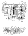
Figure 2 is an isometric view of a levering assembly and position indicator assembly therefor, in accordance with an embodiment of the disclosed concept, shown in the "connect" configuration; -
Figure 3 is a top plan view of the levering assembly and position indicator assembly therefor ofFigure 2 ; -
Figure 4 is a section view taken along line 4-4 ofFigure 3 ; -
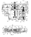
Figure 5 is an isometric view of the levering assembly and position indicator assembly therefor ofFigure 4 , shown in the "disconnect" configuration; -
Figure 6 is a top plan view of the levering assembly and position indicator assembly therefor ofFigure 5 ; -
Figure 7 is a section view taken along line 7-7 ofFigure 6 ; -
Figure 8 is an isometric view of the levering assembly and position indicator assembly therefor ofFigure 7 , shown in the "test" configuration; -
Figure 9 is a top plan view of the levering assembly and position indicator assembly therefor ofFigure 8 ; and -
Figure 10 is a section view taken along line 10-10 ofFigure 9 . - Directional phrases used herein, such as, for example, front, back, top, bottom, clockwise, counterclockwise and derivatives thereof, relate to the orientation of the elements shown in the drawings and are not limiting upon the claims unless expressly recited therein.
- As employed herein, the statement that two or more parts are "coupled" together shall mean that the parts are joined together either directly or joined through one or more intermediate parts.
- As employed herein, the term "number" shall mean one or an integer greater than one (i. e., a plurality).
-
Figure 1 shows a non-limiting example of a an electrical switching apparatus, such as acircuit breaker 2, with which alevering assembly 100 andposition indicator assembly 200 therefor, in accordance with the disclosed concept, can be employed. Thecircuit breaker 2 includes ahousing 4, separable contacts 6 (shown in simplified form) enclosed by thehousing 4, and an operating mechanism 8 (shown in simplified form) for opening and closing the separable contacts 6. In the example ofFigure 1 , thecircuit breaker housing 4 includes first and second opposingsides cover 14 extending therebetween. Thecover 14 includes awindow 16 through which anindicator 210 and avisual indication 212 of theposition indicator assembly 200 can be seen. For example and without limitation inFigure 1 , a visual indication in the form of a "connect"label 212 is visible in thewindow 16. As will be described in greater detail hereinbelow, it will be appreciated that thecircuit breaker 2 is removably disposed in acassette 300. That is, thecircuit breaker 2 can be racked or levered into and out of thecassette 300 by way of the leveringassembly 100. - More specifically, as shown in
Figures 2-10 , the leveringassembly 100 includes adrive shaft 112, and at least one rackingmember 114 movably coupled to the circuit breaker housing 4 (Figure 1 ). Oneracking member 114 is shown and described herein, for economy of disclosure and simplicity of illustration. It will be appreciated, however, that a second racking member (not shown), for example and without limitation which is disposed opposite and distal from rackingmember 114, could be employed without departing from the scope of the disclosed concept. Thedrive shaft 112 cooperates with the rackingmember 114 to facilitate racking of thecircuit breaker 2 into and out of thecassette 300. - In the non-limiting example embodiment shown and described herein, the levering
assembly 100 further includes a mountingmember 102 to which theaforementioned drive shaft 112 is pivotably coupled. As shown, for example inFigure 2 , the mountingmember 102 includes first and second opposing sides 104,106 and first and second opposing edges 108,110. Adrive screw 116, which can preferably be accessed through a corresponding opening in the circuit breaker cover 14 (Figure 1 ), extends from at or about thefirst side 104 toward thesecond side 106. The leveringassembly 100 further includes adrive rack 118, and adrive gear 120. Thedrive gear 120 is preferably disposed on thedrive shaft 112 between the first and second ends 122,124 thereof. Thefirst end 122 of theexample drive shaft 112 extends outwardly from thefirst edge 108 of the mountingmember 102, and thesecond end 124 extends outwardly from thesecond edge 110. A racking gear 128,130 is disposed on at least one of the ends 122,124. In the example shown, afirst racking gear 128 is disposed on thefirst end 122 of thedrive shaft 112, and asecond racking gear 130 is disposed on thesecond end 124. - The
drive screw 116 includes a plurality ofthreads 136, thedrive rack 118 includes a plurality ofgrooves 138, and thedrive gear 120 includes a plurality ofteeth 140. Therefore, in operation, when thedrive screw 116 is pivoted (e.g., without limitation, rotated clockwise or counterclockwise from the perspective ofFigure 2 ) thethreads 136 of thedrive screw 116 cooperate with thegrooves 138 8 of thedrive rack 118, to move thedrive rack 118 with respect to thedrive gear 120. When thedrive rack 118 moves (e.g., without limitation, toward and away from the drive shaft 112), thegrooves 138 of thedrive rack 118 cooperate with theteeth 140 of thedrive gear 120 to pivot thedrive gear 120 and thereby correspondingly pivot thedrive shaft 112. - The exemplary
position indicator assembly 200 for the leveringassembly 100, will now be described in greater detail. Specifically, theposition indicator assembly 200 includes a number of indicator gears 202,204,206, which are structured to cooperate with thedrive shaft 112. Anindication rack 208 cooperates with at least one of the indicator gears 202,204,206, as will be described in greater detail hereinbelow. In turn, anindicator 210 cooperates with theindication rack 208 to provide a visual indication 212,214,216 (e.g., without limitation, the word "connect" 212 (Figures 1 and2 ), the word "disconnect" 214 (Figure 5 ), or the word "test" 116 (Figure 8 ) displayed at window 16 (Figure 1 ) of circuit breaker cover 14 (Figure 1 )), which is indicative of the position of the circuit breaker 2 (Figure 1 ) with respect to the cassette 300 (Figure 1 ). Accordingly, when the circuit breaker 2 (Figure 1 ) is moved (e.g., without limitation, racked into or out of ) with respect to the cassette 300 (Figure 1 ) thedrive shaft 112 pivots. When thedrive shaft 112 pivots, the indicator gears 202,204,206 (three are shown) move, thereby moving theindication rack 208 and theindicator 210 to provide the aforementioned visual indication 212,214,216. - Continuing to refer to
Figure 2 , and also toFigures 3 and 4 , it will be appreciated that the indication rack is anelongated member 208, having first and second opposing ends 218,220. In the example shown and described herein, theposition indicator assembly 200 includes three indicator gears 202,204,206, although it will be appreciated that any known or suitable alternative number and/or configuration of indicator gears could be employed. Preferably, afirst indicator gear 202 is disposed on thedrive shaft 112 proximate thesecond end 124 thereof. Asecond indicator gear 204 cooperates with thefirst indicator gear 202, and with thefirst end 218 of theindication rack 208. More specifically, thefirst indicator gear 202 includes a plurality ofteeth 222, and theindication rack 208 includes a plurality ofgrooves 224 disposed at or about thefirst end 218 of theindication rack 208, and a plurality ofgrooves 226 disposed at or about thesecond end 220 of theindication rack 208. Thesecond indicator gear 204 includes afirst portion 228 having a first diameter 230 (Figure 4 ) and a plurality ofteeth 232, and asecond portion 234 having a second diameter 236 (Figure 4 ) and a plurality ofteeth 238. As shown inFigure 4 , thefirst diameter 230 is greater than thesecond diameter 236. It will be appreciated that only half of thefirst portion 228 is shown in the sectional views ofFigures 4 ,7 and10 , in order to see part of thesecond portion 234 which would otherwise be hidden. In operation, theteeth 232 of thefirst portion 228 ofsecond indicator gear 204 cooperate with theteeth 222 of thefirst indicator gear 202, and theteeth 238 of thesecond portion 234 ofsecond indicator gear 204 cooperate with thegrooves 224 of thefirst end 218 of theindication rack 208 to move theindication rack 208 toward and away from thedrive shaft 112. - The
third indicator gear 206 also includes a plurality ofteeth 240, which cooperate with thegrooves 226 of thesecond end 220 of theindication rack 208. As shown inFigures 3 and 4 , theindicator 210 preferably also includes a plurality ofteeth 242. Accordingly, in operation, theteeth 240 of thethird indicator gear 206 cooperate with theteeth 242 of theindicator 210 such that, when theindication rack 208 moves, thethird indicator gear 206 pivots, thereby moving theindicator 210 to provide the desired visual indication 212 (Figures 1 and2 ), 214 (Figures 5 ,8 and9 ) 216 (Figures 2 and8 ). - The example indicator is a
pivotable indicator drum 210 having a plurality of labels (e.g., without limitation, "connect;" "disconnect;" "test") to provide the desired visual indication 212,214,216 indicative of the corresponding one of a plurality of different positions of the circuit breaker 2 (Figure 1 ) with respect to the cassette 300 (Figure 1 ). The examplesecond indicator gear 204 is an idler gear, and the examplethird indicator gear 206 is a reverser gear. In the example shown and described herein, theidler gear 204 andreverser gear 206 preferably provide a gear reduction to suitably reduce the amount by which theindicator 210 moves for a given corresponding movement of thedrive shaft 112. It will be appreciated, however, that any known or suitable alternative number, type and/or configuration of gears (e.g., without limitation, 202,204,206) could be employed, for example, to provide a suitable increase in motion, or unchanged (e.g., direct transmission of) motion, as desired, without departing from the scope of the disclosed concept. - Accordingly, it will be appreciated that the
position indicating assembly 200 provides an uninterrupted positive mechanical position indication mechanism for accurately indicating the status of the circuit breaker 2 (Figure 1 ) to the operator. - The mechanical interaction between the levering
assembly 100 and theposition indicator assembly 200 will now be described in greater detail. Specifically, each of theaforementioned racking members 114 of the leveringassembly 100 includes a plurality ofteeth 126.Such teeth 126 cooperate with theteeth 134 of thecorresponding racking gear 130, which is coupled to thedrive shaft 112. Specifically, theexample levering assembly 100 includes first and second racking gears 128,130 having teeth 132,134 and being disposed on opposing ends 122,124, respectively, of thedrive shaft 112, as previously discussed. Accordingly, when the circuit breaker 2 (Figure 1 ) is racked into and/or out of the cassette 300 (Figure 1 ) the interaction of theteeth 126 of the rackingmember 114 with theteeth 134 of thecorresponding racking gear 130 results in a corresponding pivoting motion of thedrive shaft 112. This, in turn actuates the disclosedposition indicator assembly 200 such that a direct mechanical linkage and corresponding visual indication 212,214,216 indicative of the circuit breaker status (e.g., without limitation, position) with respect to the cassette 300 (Figure 1 ), is provided. See, for example and without limitation, "connect"visual indication 212 atwindow 16 ofcircuit breaker cover 14 in the example ofFigure 1 . - Three different configurations and corresponding visual indications 212,214,216 of the levering
assembly 100 andposition indicator assembly 200, are shown herein. It will be appreciated, however, that any known or suitable alternative number, type and/or configuration of leveringassembly 100 and/orposition indicator assembly 200 configurations and/or visual indications are contemplated by the disclosed concept. For example and without limitation,Figures 1-4 illustrate one non-limiting example embodiment in which theposition indicator assembly 200 is configured to provide a "connect"visual indication 212,Figures 5-7 illustrate a configuration of the leveringassembly 100 andposition indicator assembly 200 in which theindicator 210 provides a "disconnect"visual indication 214, andFigures 8-10 illustrate a configuration of the leveringassembly 100 andposition indicator assembly 200 corresponding to theindicator 210 providing a "test"visual indication 216. In each case, the visual indication 212 (Figures 1-4 ), 214 (Figures 5-7 ), 216 (Figures 8-10 ) provides an accurate positive indication of the circuit breaker status (e.g., without limitation, position) with respect to the cassette 300 (Figure 1 ). - While specific embodiments of the disclosed concept have been described in detail, it will be appreciated by those skilled in the art that various modifications and alternatives to those details could be developed in light of the overall teachings of the disclosure. Accordingly, the particular arrangements disclosed are meant to be illustrative only and not limiting as to the scope of the disclosed concept which is to be given the full breadth of the claims appended and any and all equivalents thereof.
-
- 1. A position indicator assembly for a levering assembly of an electrical switching apparatus, said electrical switching apparatus including a housing, said levering assembly comprising a drive shaft and a racking member movably coupled to the housing, said drive shaft cooperating with said racking member to facilitate racking of said electrical switching apparatus into and out of a cassette, said position indicator assembly comprising:
- a number of indicator gears structured to cooperate with said drive shaft;
- an indication rack cooperating with at least one of said number of indicator gears; and
- an indicator structured to cooperate with said indication rack to provide a visual indication indicative of the position of said electrical switching apparatus with respect to said cassette,
- wherein, when said electrical switching apparatus is moved with respect to said cassette, said drive shaft pivots, and
- wherein, when said drive shaft pivots, said indicator gears are structured to move, thereby moving said indication rack and said indicator in order to provide said visual indication.
- 2. The position indicator assembly of 1 wherein said indication rack is an elongated member comprising a first end and a second end disposed opposite and distal from the first end; wherein said number of indicator gears comprises a first indicator gear and a second indicator gear; wherein said first indicator gear is structured to be disposed on said drive shaft; and wherein said second indicator gear is structured to cooperate with said first indicator gear and the first end of said indication rack.
- 3. The position indicator assembly of 2 wherein said first indicator gear includes a plurality of teeth; wherein said indication rack further comprises a plurality of grooves disposed at or about the first end of said indication rack, and a plurality of grooves disposed at or about the second end of said indication rack; wherein said second indicator gear includes a first portion having a first diameter and a plurality of teeth, and a second portion having a second diameter and a plurality of teeth; wherein the first diameter is greater than the second diameter; wherein the teeth of said first portion cooperate with the teeth of said first indicator gear; and wherein the teeth of said second portion are structured to cooperate with the grooves of the first end of said indication rack to move said indication rack toward and away from said drive shaft.
- 4. The position indicator assembly of 3 wherein said number of indicator gears further comprises a third indicator gear; wherein said third indicator gear includes a plurality of teeth cooperating with the grooves of the second end of said indication rack; wherein said indicator comprises a plurality of teeth; wherein the teeth of said third indicator gear cooperate with the teeth of said indicator; and wherein, when said indication rack moves, said third indicator gear pivots, thereby moving said indicator to provide said visual indication indicative of the position of said electrical switching apparatus with respect to said cassette.
- 5. The position indicator assembly of 4 wherein said indicator is a pivotable indicator drum; wherein said pivotable indicator drum further comprises a plurality of labels; and wherein each of said labels provides a different visual indication indicative of a corresponding one of a plurality of different positions of said electrical switching apparatus with respect to said cassette.
- 6. The position indicator assembly of 4 wherein said second indicator gear is an idler gear; wherein said third indicator gear is a reverser gear; and wherein said idler gear and said reverser gear are structured to provide a gear reduction in order to reduce the amount said indicator moves for a given corresponding movement of said drive shaft.
- 7. A levering assembly for an electrical switching apparatus structured to be removably disposed in a cassette, said electrical switching apparatus including a housing, said levering assembly comprising:
- a drive shaft;
- a racking member movably coupled to the housing, said drive shaft being structured to cooperate with said racking member to rack said electrical switching apparatus into and out of said cassette; and
- a position indicator assembly comprising:
- a number of indicator gears cooperating with said drive shaft,
- an indication rack cooperating with at least one of said number of indicator gears, and
- an indicator structured to cooperate with said indication rack to provide a visual indication indicative of the position of said electrical switching apparatus with respect to said cassette,
- wherein, when said electrical switching apparatus is moved with respect to said cassette, said drive shaft pivots, and
- wherein, when said drive shaft pivots, said indicator gears move, thereby moving said indication rack and said indicator in order to provide said visual indication.
- 8. The levering assembly of 7 wherein said drive shaft comprises a first end and a second end disposed opposite and distal from the first end; wherein said indication rack of said position indicator assembly is an elongated member comprising a first end and a second end disposed opposite and distal from the first end of said elongated member; wherein said number of indicator gears comprises a first indicator gear and a second indicator gear; wherein said first indicator gear is disposed on said drive shaft proximate the second end of said drive shaft; and wherein said second indicator gear cooperates with said first indicator gear and the first end of said indication rack.
- 9. The levering assembly of 8 wherein said first indicator gear includes a plurality of teeth; wherein said indication rack further comprises a plurality of grooves disposed at or about the first end of said indication rack, and a plurality of grooves disposed at or about the second end of said indication rack; wherein said second indicator gear includes a first portion having a first diameter and a plurality of teeth, and a second portion having a second diameter and a plurality of teeth; wherein the first diameter is greater than the second diameter; wherein the teeth of said first portion cooperate with the teeth of said first indicator gear; and wherein the teeth of said second portion cooperate with the grooves of the first end of said indication rack to move said indication rack toward and away from said drive shaft.
- 10. The levering assembly of 9 wherein said number of indicator gears further comprises a third indicator gear; wherein said third indicator gear includes a plurality of teeth cooperating with the grooves of the second end of said indication rack; wherein said indicator comprises a plurality of teeth; wherein the teeth of said third indicator gear cooperate with the teeth of said indicator; and wherein, when said indication rack moves, said third indicator gear pivots, thereby moving said indicator to provide said visual indication indicative of the position of said electrical switching apparatus with respect to said cassette.
- 11. The levering assembly of 10 wherein said indicator of said position indicator assembly is a pivotable indicator drum; wherein said pivotable indicator drum further comprises a plurality of labels; and wherein each of said labels provides a different visual indication indicative of a corresponding one of a plurality of different positions of said electrical switching apparatus with respect to said cassette.
- 12. The levering assembly of 8 wherein said racking member includes a plurality of teeth; wherein said drive shaft further comprises at least one racking gear including a plurality of teeth; wherein said at least one racking gear is disposed at or about a corresponding one of the first end of said drive shaft and the second end of said drive shaft; and wherein the teeth of said racking member are structured to cooperate with the teeth of a corresponding one of said at least one racking gear, thereby pivoting said drive shaft when said electrical switching apparatus is racked into and out of said cassette.
- 13. An electrical switching apparatus structured to be removably disposed in a cassette, said electrical switching apparatus comprising:
- a housing; and
- a levering assembly comprising:
- a drive shaft,
- a racking member movably coupled to the housing, said drive shaft being structured to cooperate with said racking member to rack said electrical switching apparatus into and out of said cassette, and
- a position indicator assembly comprising:
- a number of indicator gears cooperating with said drive shaft,
- an indication rack cooperating with at least one of said number of indicator gears, and
- an indicator structured to cooperate with said indication rack to provide a visual indication indicative of the position of said electrical switching apparatus with respect to said cassette,
wherein, when said drive shaft pivots, said indicator gears move, thereby moving said indication rack and said indicator in order to provide said visual indication.
- 14. The electrical switching apparatus of 13 wherein said drive shaft of said levering assembly comprises a first end and a second end disposed opposite and distal from the first end; wherein said indication rack of said position indicator assembly is an elongated member comprising a first end and a second end disposed opposite and distal from the first end of said elongated member; wherein said number of indicator gears comprises a first indicator gear and a second indicator gear; wherein said first indicator gear is disposed on said drive shaft proximate the second end of said drive shaft; and wherein said second indicator gear cooperates with said first indicator gear and the first end of said indication rack.
- 15. The electrical switching apparatus of 14 wherein said first indicator gear includes a plurality of teeth; wherein said indication rack further comprises a plurality of grooves disposed at or about the first end of said indication rack, and a plurality of grooves disposed at or about the second end of said indication rack; wherein said second indicator gear includes a first portion having a first diameter and a plurality of teeth, and a second portion having a second diameter and a plurality of teeth; wherein the first diameter is greater than the second diameter; wherein the teeth of said first portion cooperate with the teeth of said first indicator gear; and wherein the teeth of said second portion cooperate with the grooves of the first end of said indication rack to move said indication rack toward and away from said drive shaft.
- 16. The electrical switching apparatus of 15 wherein said number of indicator gears of said position indicator assembly further comprises a third indicator gear; wherein said third indicator gear includes a plurality of teeth cooperating with the grooves of the second end of said indication rack; wherein said indicator comprises a plurality of teeth;
wherein the teeth of said third indicator gear cooperate with the teeth of said indicator; and wherein, when said indication rack moves, said third indicator gear pivots, thereby moving said indicator to provide said visual indication indicative of the position of said electrical switching apparatus with respect to said cassette. - 17. The electrical switching apparatus of 16 wherein said indicator of said position indicator assembly is a pivotable indicator drum; wherein said pivotable indicator drum further comprises a plurality of labels; and wherein each of said labels provides a different visual indication indicative of a corresponding one of a plurality of different positions of said electrical switching apparatus with respect to said cassette.
- 18. The electrical switching apparatus of 17 wherein said electrical switching apparatus is a circuit breaker; wherein the housing of said circuit breaker includes a first side, a second side, and a cover extending between the first side and the second side; wherein said racking member is pivotably coupled to a corresponding one of the first side and the second side; wherein said cover includes a window; wherein, when said circuit breaker is moved from one of said positions with respect to said cassette to another different one of said positions with respect to said cassette, said indicator drum moves to display the corresponding one of said labels in said window.
- 19. The electrical switching apparatus of 13 wherein said racking member of said levering assembly includes a plurality of teeth; wherein said drive shaft further comprises at least one racking gear including a plurality of teeth; wherein said at least one racking gear is disposed at or about a corresponding one of the first end of said drive shaft and the second end of said drive shaft; and wherein, when said electrical switching apparatus is racked into and out of said cassette the teeth of said racking member cooperate with the teeth of a corresponding one of said at least one racking gear and said drive shaft pivots.
- 20. The electrical switching apparatus of 19 wherein said levering assembly further comprises a mounting member, a drive screw, a drive rack, and a drive gear; wherein said mounting member includes a first side, a second side disposed opposite and distal from the first side of said mounting member, a first edge, and a second edge disposed opposite and distal from the first edge; wherein said drive screw extends from at or about the first side toward the second side; wherein said drive gear is disposed on said drive shaft between the first end of said drive shaft and the second end of said drive shaft; wherein said drive shaft is pivotably coupled to said mounting member; wherein the first end of said drive shaft extends outwardly from the first edge of said mounting member; wherein the second end of said drive shaft extends outwardly from the second edge of said mounting member; wherein said at least one racking gear is a first racking gear disposed on the first end of said drive shaft and a second racking gear disposed on the second end of said drive shaft; wherein said drive screw includes a plurality of threads; wherein said drive rack includes a plurality of grooves; wherein said drive gear includes a plurality of teeth; wherein, when said drive screw is pivoted, the threads of said drive screw cooperate with the grooves of said drive rack to move said drive rack with respect to said drive gear; and wherein, when said drive rack moves, the grooves of said drive rack cooperate with the teeth of said drive gear, thereby pivoting said drive gear and said drive shaft.
Claims (15)
- A position indicator assembly (200) for a levering assembly (100) of an electrical switching apparatus (2), said electrical switching apparatus (2) including a housing (4), said levering assembly (100) comprising a drive shaft (112) and a racking member (114) movably coupled to the housing (4), said drive shaft (112) cooperating with said racking member (114) to facilitate racking of said electrical switching apparatus (2) into and out of a cassette (300), said position indicator assembly (200) comprising:a number of indicator gears (202,204,206) structured to cooperate with said drive shaft (112);an indication rack (208) cooperating with at least one of said number of indicator gears (202,204,206); andan indicator (210) structured to cooperate with said indication rack (208) to provide a visual indication (212,214,216) indicative of the position of said electrical switching apparatus (2) with respect to said cassette (300),wherein, when said electrical switching apparatus (2) is moved with respect to said cassette (300), said drive shaft (112) pivots, andwherein, when said drive shaft (112) pivots, said indicator gears (202,204,206) are structured to move, thereby moving said indication rack (208) and said indicator (210) in order to provide said visual indication (212,214,216).
- The position indicator assembly (200) of claim 1 wherein said indication rack is an elongated member (208) comprising a first end (218) and a second end (220) disposed opposite and distal from the first end (218); wherein said number of indicator gears comprises a first indicator gear (202) and a second indicator gear (204); wherein said first indicator gear (202) is structured to be disposed on said drive shaft (112); and wherein said second indicator gear (204) is structured to cooperate with said first indicator gear (202) and the first end (218) of said indication rack (208).
- The position indicator assembly (200) of claim 2 wherein said first indicator gear (202) includes a plurality of teeth (222); wherein said indication rack (208) further comprises a plurality of grooves (224) disposed at or about the first end (218) of said indication rack (208), and a plurality of grooves (226) disposed at or about the second end (220) of said indication rack (208); wherein said second indicator gear (204) includes a first portion (228) having a first diameter (230) and a plurality of teeth (232), and a second portion (234) having a second diameter (236) and a plurality of teeth (238); wherein the first diameter (230) is greater than the second diameter (236); wherein the teeth (232) of said first portion (228) cooperate with the teeth (222) of said first indicator gear (202); and wherein the teeth (238) of said second portion (234) are structured to cooperate with the grooves (224) of the first end (218) of said indication rack (208) to move said indication rack (208) toward and away from said drive shaft (112).
- The position indicator assembly (200) of claim 3 wherein said number of indicator gears further comprises a third indicator gear (206); wherein said third indicator gear (206) includes a plurality of teeth (240) cooperating with the grooves (226) of the second end (220) of said indication rack (208); wherein said indicator (210) comprises a plurality of teeth (242); wherein the teeth (240) of said third indicator gear (206) cooperate with the teeth (242) of said indicator (210); and wherein, when said indication rack (208) moves, said third indicator gear (206) pivots, thereby moving said indicator (210) to provide said visual indication indicative of the position of said electrical switching apparatus (2) with respect to said cassette (300).
- The position indicator assembly (200) of claim 4 wherein said indicator is a pivotable indicator drum (210); wherein said pivotable indicator drum (210) further comprises a plurality of labels (212,214,216); and wherein each of said labels (212,214,216) provides a different visual indication indicative of a corresponding one of a plurality of different positions of said electrical switching apparatus (2) with respect to said cassette (300).
- The position indicator assembly (200) of claim 4 wherein said second indicator gear is an idler gear (204); wherein said third indicator gear is a reverser gear (206); and wherein said idler gear (204) and said reverser gear (206) are structured to provide a gear reduction in order to reduce the amount said indicator (210) moves for a given corresponding movement of said drive shaft (112).
- A levering assembly (100) for an electrical switching apparatus (2) structured to be removably disposed in a cassette (300), said electrical switching apparatus (2) including a housing (4), said levering assembly (100) comprising:a drive shaft (112);a racking member (114) movably coupled to the housing (4), said drive shaft (112) being structured to cooperate with said racking member (114) to rack said electrical switching apparatus (2) into and out of said cassette (300); anda position indicator assembly (200) comprising:a number of indicator gears (202,204,206) cooperating with said drive shaft (112),an indication rack (208) cooperating with at least one of said number of indicator gears (202,204,206), andan indicator (210) structured to cooperate with said indication rack (208) to provide a visual indication (212,214,216) indicative of the position of said electrical switching apparatus (2) with respect to said cassette (300),wherein, when said electrical switching apparatus (2) is moved with respect to said cassette (300), said drive shaft (112) pivots, andwherein, when said drive shaft (112) pivots, said indicator gears (202,204,206) move, thereby moving said indication rack (208) and said indicator (210) in order to provide said visual indication (212,214,216).
- The levering assembly (100) of claim 7 wherein said drive shaft (112) comprises a first end (122) and a second end (124) disposed opposite and distal from the first end (122); wherein said indication rack (208) of said position indicator assembly (200) is an elongated member (208) comprising a first end (218) and a second end (220) disposed opposite and distal from the first end (218) of said elongated member (208); wherein said number of indicator gears comprises a first indicator gear (202) and a second indicator gear (204); wherein said first indicator gear (202) is disposed on said drive shaft (112) proximate the second end (124) of said drive shaft (112); and wherein said second indicator gear (204) cooperates with said first indicator gear (202) and the first end (218) of said indication rack (208).
- The levering assembly (100) of claim 8 wherein said first indicator gear (202) includes a plurality of teeth (222); wherein said indication rack (208) further comprises a plurality of grooves (224) disposed at or about the first end (218) of said indication rack (208), and a plurality of grooves (226) disposed at or about the second end (220) of said indication rack (208); wherein said second indicator gear (204) includes a first portion (228) having a first diameter (230) and a plurality of teeth (232), and a second portion (234) having a second diameter (236) and a plurality of teeth (238); wherein the first diameter (230) is greater than the second diameter (236); wherein the teeth (232) of said first portion (228) cooperate with the teeth (222) of said first indicator gear (202); and wherein the teeth (238) of said second portion (234) cooperate with the grooves (224) of the first end (218) of said indication rack (208) to move said indication rack (208) toward and away from said drive shaft (112).
- The levering assembly (100) of claim 9 wherein said number of indicator gears further comprises a third indicator gear (206); wherein said third indicator gear (206) includes a plurality of teeth (240) cooperating with the grooves (226) of the second end (220) of said indication rack (208); wherein said indicator (210) comprises a plurality of teeth (242); wherein the teeth (240) of said third indicator gear (206) cooperate with the teeth (242) of said indicator (210); and wherein, when said indication rack (208) moves, said third indicator gear (206) pivots, thereby moving said indicator (210) to provide said visual indication indicative of the position of said electrical switching apparatus (2) with respect to said cassette (300).
- The levering assembly (100) of claim 10 wherein said indicator (210) of said position indicator assembly (200) is a pivotable indicator drum (210); wherein said pivotable indicator drum (210) further comprises a plurality of labels (212,214,216); and wherein each of said labels (212,214,216) provides a different visual indication indicative of a corresponding one of a plurality of different positions of said electrical switching apparatus (2) with respect to said cassette (300).
- The levering assembly (100) of claim 8 wherein said racking member (114) includes a plurality of teeth (126); wherein said drive shaft (112) further comprises at least one racking gear (128,130) including a plurality of teeth (132,134); wherein said at least one racking gear (128,130) is disposed at or about a corresponding one of the first end (122) of said drive shaft (112) and the second end (124) of said drive shaft (112); and wherein the teeth (126) of said racking member (114) are structured to cooperate with the teeth (132,134) of a corresponding one of said at least one racking gear (128,130), thereby pivoting said drive shaft (112) when said electrical switching apparatus (2) is racked into and out of said cassette (300).
- An electrical switching apparatus (2) structured to be removably disposed in a cassette (300), said electrical switching apparatus (2) comprising:a housing (4); andthe levering assembly (100) as set forth in any one of claims 7 to 12.
- The electrical switching apparatus (2) of claim 13, wherein said electrical switching apparatus is a circuit breaker (2); wherein the housing (4) of said circuit breaker (2) includes a first side (10), a second side (12), and a cover (14) extending between the first side (10) and the second side (12); wherein said racking member (114) is pivotably coupled to a corresponding one of the first side (10) and the second side (12); wherein said cover (14) includes a window (16); wherein, when said circuit breaker (2) is moved from one of said positions with respect to said cassette (300) to another different one of said positions with respect to said cassette (300), said indicator drum (210) moves to display the corresponding one of said labels (212,214,216) in said window (16).
- The electrical switching apparatus (2) of claim 13, wherein said levering assembly (100) further comprises a mounting member (102), a drive screw (116), a drive rack (118), and a drive gear (120); wherein said mounting member (102) includes a first side (104), a second side (106) disposed opposite and distal from the first side (104) of said mounting member (102), a first edge (108), and a second edge (110) disposed opposite and distal from the first edge (108); wherein said drive screw (116) extends from at or about the first side (104) toward the second side (106); wherein said drive gear (120) is disposed on said drive shaft (112) between the first end (122) of said drive shaft (112) and the second end (124) of said drive shaft (112); wherein said drive shaft (112) is pivotably coupled to said mounting member (102); wherein the first end (122) of said drive shaft (112) extends outwardly from the first edge (108) of said mounting member (102); wherein the second end (124) of said drive shaft (112) extends outwardly from the second edge (110) of said mounting member (102); wherein said at least one racking gear is a first racking gear (128) disposed on the first end (122) of said drive shaft (112) and a second racking gear (130) disposed on the second end (124) of said drive shaft (112); wherein said drive screw (116) includes a plurality of threads (136); wherein said drive rack (118) includes a plurality of grooves (138); wherein said drive gear (120) includes a plurality of teeth (140); wherein, when said drive screw (116) is pivoted, the threads (136) of said drive screw (116) cooperate with the grooves (138) of said drive rack (118) to move said drive rack (118) with respect to said drive gear (120); and wherein, when said drive rack (118) moves, the grooves (138) of said drive rack (118) cooperate with the teeth (140) of said drive gear (120), thereby pivoting said drive gear (120) and said drive shaft (112).
Applications Claiming Priority (1)
| Application Number | Priority Date | Filing Date | Title |
|---|---|---|---|
| US12/777,638 US8247716B2 (en) | 2010-05-11 | 2010-05-11 | Electrical switching apparatus, and levering assembly and position indicator assembly therefor |
Publications (3)
| Publication Number | Publication Date |
|---|---|
| EP2387054A2 true EP2387054A2 (en) | 2011-11-16 |
| EP2387054A3 EP2387054A3 (en) | 2012-07-11 |
| EP2387054B1 EP2387054B1 (en) | 2014-04-16 |
Family
ID=44326205
Family Applications (1)
| Application Number | Title | Priority Date | Filing Date |
|---|---|---|---|
| EP11003865.0A Active EP2387054B1 (en) | 2010-05-11 | 2011-05-11 | Electrical switching apparatus, and levering assembly and position indicator assembly therefor |
Country Status (4)
| Country | Link |
|---|---|
| US (1) | US8247716B2 (en) |
| EP (1) | EP2387054B1 (en) |
| CN (1) | CN102254723B (en) |
| CA (1) | CA2739947C (en) |
Cited By (2)
| Publication number | Priority date | Publication date | Assignee | Title |
|---|---|---|---|---|
| WO2015075096A1 (en) * | 2013-11-22 | 2015-05-28 | Eaton Industries (Netherlands) B.V. | Switching device |
| US10121624B2 (en) | 2016-12-27 | 2018-11-06 | Lsis Co., Ltd. | Position indicator of air circuit breaker |
Families Citing this family (11)
| Publication number | Priority date | Publication date | Assignee | Title |
|---|---|---|---|---|
| US8264809B2 (en) * | 2010-09-15 | 2012-09-11 | General Electric Company | System and apparatus for circuit protection within an equipment enclosure |
| US8953305B2 (en) | 2012-12-04 | 2015-02-10 | Eaton Corporation | Electrical switching apparatus and levering assembly therefor |
| US9835235B2 (en) * | 2013-03-13 | 2017-12-05 | Asco Power Technologies, L.P. | Lead screw operated rack-in mechanism |
| US9673595B2 (en) * | 2013-10-31 | 2017-06-06 | Eaton Corporation | Withdrawable contactor trucks with integral motorized levering-in, related switchgear, kits and methods |
| CN104377057B (en) * | 2014-11-13 | 2017-05-10 | 无锡江南奕帆电力传动科技股份有限公司 | Breaker position indication device beneficial to observation |
| WO2017011536A1 (en) * | 2015-07-13 | 2017-01-19 | Abb Schweiz Ag | Mechanical rack position indicator |
| US10211608B2 (en) * | 2017-05-25 | 2019-02-19 | Eaton Intelligent Power Limited | Mechanical coupling devices for motorized levering-in assemblies, related electrical apparatus and methods |
| US10564685B2 (en) * | 2017-11-09 | 2020-02-18 | Quanta Computer Inc. | Compact tool-less general purpose graphic processing units (GPGPU) module |
| CN112103144B (en) * | 2019-06-18 | 2025-07-15 | 浙江正泰电器股份有限公司 | Plug-in miniature circuit breaker |
| EP4260355A4 (en) | 2020-12-14 | 2024-09-04 | ABB S.p.A. | Adjustment mechanism for circuit breaker and corresponding circuit breaker |
| KR102636475B1 (en) * | 2021-03-30 | 2024-02-13 | 엘에스일렉트릭(주) | Vacuum circuit breaker with lift hook |
Citations (1)
| Publication number | Priority date | Publication date | Assignee | Title |
|---|---|---|---|---|
| US7019229B1 (en) | 2004-09-03 | 2006-03-28 | Eaton Corporation | Door interlock assembly and draw-out circuit breaker assembly employing the same |
Family Cites Families (8)
| Publication number | Priority date | Publication date | Assignee | Title |
|---|---|---|---|---|
| US4012610A (en) | 1975-04-14 | 1977-03-15 | General Electric Company | Drawout apparatus having improved trip interlock |
| US6005208A (en) | 1998-03-03 | 1999-12-21 | General Electric Company | Industrial draw-out circuit breaker electrical connection indication |
| FR2783366B1 (en) | 1998-09-11 | 2000-11-24 | Schneider Electric Ind Sa | ELECTRICAL SWITCHING EQUIPMENT INCLUDING A DISCONNECT CIRCUIT BREAKER AND INDICATORS OF THE POSITION OF THE CIRCUIT BREAKER IN ITS CHASSIS |
| FR2806548B1 (en) * | 2000-03-17 | 2002-08-23 | Ge Power Controls France | EXTRACTABLE MECHANISM FOR CIRCUIT BREAKERS |
| US7485817B2 (en) | 2005-09-26 | 2009-02-03 | Eaton Corporation | Electrical switching apparatus and adjustable mounting assembly therefor |
| US7486499B2 (en) | 2007-07-02 | 2009-02-03 | Eaton Corporation | Electrical switching apparatus and securing mechanism therefor |
| US7847203B2 (en) * | 2008-04-15 | 2010-12-07 | General Electric Company | System and method for indicating a position of an electrical distribution device |
| US8431845B2 (en) * | 2010-09-20 | 2013-04-30 | Eaton Corporation | Electrical switching apparatus and levering assembly therefor |
-
2010
- 2010-05-11 US US12/777,638 patent/US8247716B2/en active Active
-
2011
- 2011-05-11 EP EP11003865.0A patent/EP2387054B1/en active Active
- 2011-05-11 CA CA2739947A patent/CA2739947C/en active Active
- 2011-05-11 CN CN201110174315.4A patent/CN102254723B/en active Active
Patent Citations (1)
| Publication number | Priority date | Publication date | Assignee | Title |
|---|---|---|---|---|
| US7019229B1 (en) | 2004-09-03 | 2006-03-28 | Eaton Corporation | Door interlock assembly and draw-out circuit breaker assembly employing the same |
Cited By (2)
| Publication number | Priority date | Publication date | Assignee | Title |
|---|---|---|---|---|
| WO2015075096A1 (en) * | 2013-11-22 | 2015-05-28 | Eaton Industries (Netherlands) B.V. | Switching device |
| US10121624B2 (en) | 2016-12-27 | 2018-11-06 | Lsis Co., Ltd. | Position indicator of air circuit breaker |
Also Published As
| Publication number | Publication date |
|---|---|
| CN102254723A (en) | 2011-11-23 |
| US8247716B2 (en) | 2012-08-21 |
| US20110278141A1 (en) | 2011-11-17 |
| EP2387054A3 (en) | 2012-07-11 |
| EP2387054B1 (en) | 2014-04-16 |
| CA2739947C (en) | 2017-08-29 |
| CA2739947A1 (en) | 2011-11-11 |
| CN102254723B (en) | 2015-04-22 |
Similar Documents
| Publication | Publication Date | Title |
|---|---|---|
| CA2739947C (en) | Electrical switching apparatus, and levering assembly and position indicator assembly therefor | |
| US8431845B2 (en) | Electrical switching apparatus and levering assembly therefor | |
| US5757260A (en) | Medium voltage switchgear with means for changing fuses | |
| EP2110905B1 (en) | System and method for indicating a position of an electrical distribution device | |
| JP5059891B2 (en) | Vacuum breaker drawing / drawing position display device | |
| US8331081B2 (en) | Electrical system, and electrical switching apparatus and shutter assembly therefor | |
| EP2149948B1 (en) | Draw-out mechanism for molded case circuit breakers | |
| US8953305B2 (en) | Electrical switching apparatus and levering assembly therefor | |
| KR20100080051A (en) | Run/test position indicator devices in circuit breaker | |
| JP5656660B2 (en) | Switchgear | |
| US8644007B2 (en) | Electrical switching apparatus, and racking assembly and secondary disconnect assembly therefor | |
| CN118412779B (en) | Compact air insulation medium voltage switchgear | |
| US7781689B2 (en) | Network protector retrofit handle assembly | |
| CN208226433U (en) | Low voltage drawer Propulsive interlocking device | |
| CN202423938U (en) | Closing interlock and capacitor cabinet | |
| CA1127691A (en) | Drawout switchgear with telescoping cam shaft | |
| CN223079580U (en) | An assembled power distribution cabinet | |
| CN220367868U (en) | Switching transmission mechanism and circuit breaker with same | |
| KR100430224B1 (en) | Entrance/exit position indication apparatus for circuit breaker for distributing board | |
| JPH0323771Y2 (en) | ||
| CN118136429A (en) | A kind of isolating/grounding switch and GIS | |
| EP1427079A1 (en) | Slide-in frame and withdrawable circuit-breaker | |
| KR20130071188A (en) | Withdraw prevention mechanism for air circuit breaker and air circuit breaker having the withdraw prevention mechanism |
Legal Events
| Date | Code | Title | Description |
|---|---|---|---|
| AK | Designated contracting states |
Kind code of ref document: A2 Designated state(s): AL AT BE BG CH CY CZ DE DK EE ES FI FR GB GR HR HU IE IS IT LI LT LU LV MC MK MT NL NO PL PT RO RS SE SI SK SM TR |
|
| AX | Request for extension of the european patent |
Extension state: BA ME |
|
| PUAI | Public reference made under article 153(3) epc to a published international application that has entered the european phase |
Free format text: ORIGINAL CODE: 0009012 |
|
| PUAL | Search report despatched |
Free format text: ORIGINAL CODE: 0009013 |
|
| AK | Designated contracting states |
Kind code of ref document: A3 Designated state(s): AL AT BE BG CH CY CZ DE DK EE ES FI FR GB GR HR HU IE IS IT LI LT LU LV MC MK MT NL NO PL PT RO RS SE SI SK SM TR |
|
| AX | Request for extension of the european patent |
Extension state: BA ME |
|
| RIC1 | Information provided on ipc code assigned before grant |
Ipc: H01H 9/16 20060101AFI20120601BHEP Ipc: H01H 71/04 20060101ALI20120601BHEP |
|
| RAP1 | Party data changed (applicant data changed or rights of an application transferred) |
Owner name: EATON CORPORATION |
|
| 17P | Request for examination filed |
Effective date: 20130109 |
|
| GRAP | Despatch of communication of intention to grant a patent |
Free format text: ORIGINAL CODE: EPIDOSNIGR1 |
|
| INTG | Intention to grant announced |
Effective date: 20131017 |
|
| RIN1 | Information on inventor provided before grant (corrected) |
Inventor name: RODGERS, CRAIG A. Inventor name: BOGDON, ERIK R. Inventor name: WEISTER, NATHAN J. |
|
| GRAS | Grant fee paid |
Free format text: ORIGINAL CODE: EPIDOSNIGR3 |
|
| GRAA | (expected) grant |
Free format text: ORIGINAL CODE: 0009210 |
|
| AK | Designated contracting states |
Kind code of ref document: B1 Designated state(s): AL AT BE BG CH CY CZ DE DK EE ES FI FR GB GR HR HU IE IS IT LI LT LU LV MC MK MT NL NO PL PT RO RS SE SI SK SM TR |
|
| REG | Reference to a national code |
Ref country code: GB Ref legal event code: FG4D |
|
| REG | Reference to a national code |
Ref country code: CH Ref legal event code: EP |
|
| REG | Reference to a national code |
Ref country code: AT Ref legal event code: REF Ref document number: 662988 Country of ref document: AT Kind code of ref document: T Effective date: 20140515 |
|
| REG | Reference to a national code |
Ref country code: IE Ref legal event code: FG4D |
|
| REG | Reference to a national code |
Ref country code: DE Ref legal event code: R096 Ref document number: 602011006114 Country of ref document: DE Effective date: 20140528 |
|
| REG | Reference to a national code |
Ref country code: AT Ref legal event code: MK05 Ref document number: 662988 Country of ref document: AT Kind code of ref document: T Effective date: 20140416 |
|
| REG | Reference to a national code |
Ref country code: NL Ref legal event code: VDEP Effective date: 20140416 |
|
| REG | Reference to a national code |
Ref country code: LT Ref legal event code: MG4D |
|
| PG25 | Lapsed in a contracting state [announced via postgrant information from national office to epo] |
Ref country code: NO Free format text: LAPSE BECAUSE OF FAILURE TO SUBMIT A TRANSLATION OF THE DESCRIPTION OR TO PAY THE FEE WITHIN THE PRESCRIBED TIME-LIMIT Effective date: 20140716 Ref country code: FI Free format text: LAPSE BECAUSE OF FAILURE TO SUBMIT A TRANSLATION OF THE DESCRIPTION OR TO PAY THE FEE WITHIN THE PRESCRIBED TIME-LIMIT Effective date: 20140416 Ref country code: IS Free format text: LAPSE BECAUSE OF FAILURE TO SUBMIT A TRANSLATION OF THE DESCRIPTION OR TO PAY THE FEE WITHIN THE PRESCRIBED TIME-LIMIT Effective date: 20140816 Ref country code: GR Free format text: LAPSE BECAUSE OF FAILURE TO SUBMIT A TRANSLATION OF THE DESCRIPTION OR TO PAY THE FEE WITHIN THE PRESCRIBED TIME-LIMIT Effective date: 20140717 Ref country code: NL Free format text: LAPSE BECAUSE OF FAILURE TO SUBMIT A TRANSLATION OF THE DESCRIPTION OR TO PAY THE FEE WITHIN THE PRESCRIBED TIME-LIMIT Effective date: 20140416 Ref country code: BG Free format text: LAPSE BECAUSE OF FAILURE TO SUBMIT A TRANSLATION OF THE DESCRIPTION OR TO PAY THE FEE WITHIN THE PRESCRIBED TIME-LIMIT Effective date: 20140716 Ref country code: LT Free format text: LAPSE BECAUSE OF FAILURE TO SUBMIT A TRANSLATION OF THE DESCRIPTION OR TO PAY THE FEE WITHIN THE PRESCRIBED TIME-LIMIT Effective date: 20140416 Ref country code: CY Free format text: LAPSE BECAUSE OF FAILURE TO SUBMIT A TRANSLATION OF THE DESCRIPTION OR TO PAY THE FEE WITHIN THE PRESCRIBED TIME-LIMIT Effective date: 20140416 |
|
| PG25 | Lapsed in a contracting state [announced via postgrant information from national office to epo] |
Ref country code: AT Free format text: LAPSE BECAUSE OF FAILURE TO SUBMIT A TRANSLATION OF THE DESCRIPTION OR TO PAY THE FEE WITHIN THE PRESCRIBED TIME-LIMIT Effective date: 20140416 Ref country code: ES Free format text: LAPSE BECAUSE OF FAILURE TO SUBMIT A TRANSLATION OF THE DESCRIPTION OR TO PAY THE FEE WITHIN THE PRESCRIBED TIME-LIMIT Effective date: 20140416 Ref country code: SE Free format text: LAPSE BECAUSE OF FAILURE TO SUBMIT A TRANSLATION OF THE DESCRIPTION OR TO PAY THE FEE WITHIN THE PRESCRIBED TIME-LIMIT Effective date: 20140416 Ref country code: HR Free format text: LAPSE BECAUSE OF FAILURE TO SUBMIT A TRANSLATION OF THE DESCRIPTION OR TO PAY THE FEE WITHIN THE PRESCRIBED TIME-LIMIT Effective date: 20140416 Ref country code: LV Free format text: LAPSE BECAUSE OF FAILURE TO SUBMIT A TRANSLATION OF THE DESCRIPTION OR TO PAY THE FEE WITHIN THE PRESCRIBED TIME-LIMIT Effective date: 20140416 Ref country code: RS Free format text: LAPSE BECAUSE OF FAILURE TO SUBMIT A TRANSLATION OF THE DESCRIPTION OR TO PAY THE FEE WITHIN THE PRESCRIBED TIME-LIMIT Effective date: 20140416 Ref country code: PL Free format text: LAPSE BECAUSE OF FAILURE TO SUBMIT A TRANSLATION OF THE DESCRIPTION OR TO PAY THE FEE WITHIN THE PRESCRIBED TIME-LIMIT Effective date: 20140416 |
|
| PG25 | Lapsed in a contracting state [announced via postgrant information from national office to epo] |
Ref country code: PT Free format text: LAPSE BECAUSE OF FAILURE TO SUBMIT A TRANSLATION OF THE DESCRIPTION OR TO PAY THE FEE WITHIN THE PRESCRIBED TIME-LIMIT Effective date: 20140818 |
|
| REG | Reference to a national code |
Ref country code: CH Ref legal event code: PL |
|
| REG | Reference to a national code |
Ref country code: DE Ref legal event code: R097 Ref document number: 602011006114 Country of ref document: DE |
|
| PG25 | Lapsed in a contracting state [announced via postgrant information from national office to epo] |
Ref country code: CZ Free format text: LAPSE BECAUSE OF FAILURE TO SUBMIT A TRANSLATION OF THE DESCRIPTION OR TO PAY THE FEE WITHIN THE PRESCRIBED TIME-LIMIT Effective date: 20140416 Ref country code: BE Free format text: LAPSE BECAUSE OF FAILURE TO SUBMIT A TRANSLATION OF THE DESCRIPTION OR TO PAY THE FEE WITHIN THE PRESCRIBED TIME-LIMIT Effective date: 20140416 Ref country code: RO Free format text: LAPSE BECAUSE OF FAILURE TO SUBMIT A TRANSLATION OF THE DESCRIPTION OR TO PAY THE FEE WITHIN THE PRESCRIBED TIME-LIMIT Effective date: 20140416 Ref country code: SK Free format text: LAPSE BECAUSE OF FAILURE TO SUBMIT A TRANSLATION OF THE DESCRIPTION OR TO PAY THE FEE WITHIN THE PRESCRIBED TIME-LIMIT Effective date: 20140416 Ref country code: LI Free format text: LAPSE BECAUSE OF NON-PAYMENT OF DUE FEES Effective date: 20140531 Ref country code: CH Free format text: LAPSE BECAUSE OF NON-PAYMENT OF DUE FEES Effective date: 20140531 Ref country code: DK Free format text: LAPSE BECAUSE OF FAILURE TO SUBMIT A TRANSLATION OF THE DESCRIPTION OR TO PAY THE FEE WITHIN THE PRESCRIBED TIME-LIMIT Effective date: 20140416 Ref country code: MC Free format text: LAPSE BECAUSE OF FAILURE TO SUBMIT A TRANSLATION OF THE DESCRIPTION OR TO PAY THE FEE WITHIN THE PRESCRIBED TIME-LIMIT Effective date: 20140416 Ref country code: EE Free format text: LAPSE BECAUSE OF FAILURE TO SUBMIT A TRANSLATION OF THE DESCRIPTION OR TO PAY THE FEE WITHIN THE PRESCRIBED TIME-LIMIT Effective date: 20140416 |
|
| PLBE | No opposition filed within time limit |
Free format text: ORIGINAL CODE: 0009261 |
|
| STAA | Information on the status of an ep patent application or granted ep patent |
Free format text: STATUS: NO OPPOSITION FILED WITHIN TIME LIMIT |
|
| REG | Reference to a national code |
Ref country code: IE Ref legal event code: MM4A |
|
| 26N | No opposition filed |
Effective date: 20150119 |
|
| PG25 | Lapsed in a contracting state [announced via postgrant information from national office to epo] |
Ref country code: IE Free format text: LAPSE BECAUSE OF NON-PAYMENT OF DUE FEES Effective date: 20140511 |
|
| REG | Reference to a national code |
Ref country code: DE Ref legal event code: R097 Ref document number: 602011006114 Country of ref document: DE Effective date: 20150119 |
|
| PG25 | Lapsed in a contracting state [announced via postgrant information from national office to epo] |
Ref country code: SI Free format text: LAPSE BECAUSE OF FAILURE TO SUBMIT A TRANSLATION OF THE DESCRIPTION OR TO PAY THE FEE WITHIN THE PRESCRIBED TIME-LIMIT Effective date: 20140416 |
|
| PG25 | Lapsed in a contracting state [announced via postgrant information from national office to epo] |
Ref country code: MT Free format text: LAPSE BECAUSE OF FAILURE TO SUBMIT A TRANSLATION OF THE DESCRIPTION OR TO PAY THE FEE WITHIN THE PRESCRIBED TIME-LIMIT Effective date: 20140416 |
|
| REG | Reference to a national code |
Ref country code: FR Ref legal event code: PLFP Year of fee payment: 6 |
|
| PG25 | Lapsed in a contracting state [announced via postgrant information from national office to epo] |
Ref country code: SM Free format text: LAPSE BECAUSE OF FAILURE TO SUBMIT A TRANSLATION OF THE DESCRIPTION OR TO PAY THE FEE WITHIN THE PRESCRIBED TIME-LIMIT Effective date: 20140416 |
|
| PG25 | Lapsed in a contracting state [announced via postgrant information from national office to epo] |
Ref country code: LU Free format text: LAPSE BECAUSE OF NON-PAYMENT OF DUE FEES Effective date: 20140511 Ref country code: TR Free format text: LAPSE BECAUSE OF FAILURE TO SUBMIT A TRANSLATION OF THE DESCRIPTION OR TO PAY THE FEE WITHIN THE PRESCRIBED TIME-LIMIT Effective date: 20140416 Ref country code: HU Free format text: LAPSE BECAUSE OF FAILURE TO SUBMIT A TRANSLATION OF THE DESCRIPTION OR TO PAY THE FEE WITHIN THE PRESCRIBED TIME-LIMIT; INVALID AB INITIO Effective date: 20110511 |
|
| REG | Reference to a national code |
Ref country code: FR Ref legal event code: PLFP Year of fee payment: 7 |
|
| REG | Reference to a national code |
Ref country code: FR Ref legal event code: PLFP Year of fee payment: 8 |
|
| PG25 | Lapsed in a contracting state [announced via postgrant information from national office to epo] |
Ref country code: MK Free format text: LAPSE BECAUSE OF FAILURE TO SUBMIT A TRANSLATION OF THE DESCRIPTION OR TO PAY THE FEE WITHIN THE PRESCRIBED TIME-LIMIT Effective date: 20140416 |
|
| PG25 | Lapsed in a contracting state [announced via postgrant information from national office to epo] |
Ref country code: AL Free format text: LAPSE BECAUSE OF FAILURE TO SUBMIT A TRANSLATION OF THE DESCRIPTION OR TO PAY THE FEE WITHIN THE PRESCRIBED TIME-LIMIT Effective date: 20140416 |
|
| PGFP | Annual fee paid to national office [announced via postgrant information from national office to epo] |
Ref country code: GB Payment date: 20180419 Year of fee payment: 8 |
|
| REG | Reference to a national code |
Ref country code: GB Ref legal event code: 732E Free format text: REGISTERED BETWEEN 20181115 AND 20181130 |
|
| REG | Reference to a national code |
Ref country code: DE Ref legal event code: R082 Ref document number: 602011006114 Country of ref document: DE Ref country code: DE Ref legal event code: R081 Ref document number: 602011006114 Country of ref document: DE Owner name: EATON INTELLIGENT POWER LIMITED, IE Free format text: FORMER OWNER: EATON CORP., CLEVELAND, OHIO, US |
|
| GBPC | Gb: european patent ceased through non-payment of renewal fee |
Effective date: 20190511 |
|
| PG25 | Lapsed in a contracting state [announced via postgrant information from national office to epo] |
Ref country code: GB Free format text: LAPSE BECAUSE OF NON-PAYMENT OF DUE FEES Effective date: 20190511 |
|
| P01 | Opt-out of the competence of the unified patent court (upc) registered |
Effective date: 20230521 |
|
| PGFP | Annual fee paid to national office [announced via postgrant information from national office to epo] |
Ref country code: DE Payment date: 20250423 Year of fee payment: 15 |
|
| PGFP | Annual fee paid to national office [announced via postgrant information from national office to epo] |
Ref country code: IT Payment date: 20250423 Year of fee payment: 15 |
|
| PGFP | Annual fee paid to national office [announced via postgrant information from national office to epo] |
Ref country code: FR Payment date: 20250423 Year of fee payment: 15 |