EP2387040A2 - Iodide scintillator for radiation detection - Google Patents
Iodide scintillator for radiation detection Download PDFInfo
- Publication number
- EP2387040A2 EP2387040A2 EP11165485A EP11165485A EP2387040A2 EP 2387040 A2 EP2387040 A2 EP 2387040A2 EP 11165485 A EP11165485 A EP 11165485A EP 11165485 A EP11165485 A EP 11165485A EP 2387040 A2 EP2387040 A2 EP 2387040A2
- Authority
- EP
- European Patent Office
- Prior art keywords
- scintillator material
- single crystal
- scintillator
- formula
- radiation
- Prior art date
- Legal status (The legal status is an assumption and is not a legal conclusion. Google has not performed a legal analysis and makes no representation as to the accuracy of the status listed.)
- Granted
Links
Images




Classifications
-
- C—CHEMISTRY; METALLURGY
- C09—DYES; PAINTS; POLISHES; NATURAL RESINS; ADHESIVES; COMPOSITIONS NOT OTHERWISE PROVIDED FOR; APPLICATIONS OF MATERIALS NOT OTHERWISE PROVIDED FOR
- C09K—MATERIALS FOR MISCELLANEOUS APPLICATIONS, NOT PROVIDED FOR ELSEWHERE
- C09K11/00—Luminescent materials, e.g. electroluminescent or chemiluminescent
- C09K11/08—Luminescent materials, e.g. electroluminescent or chemiluminescent containing inorganic luminescent materials
- C09K11/77—Luminescent materials, e.g. electroluminescent or chemiluminescent containing inorganic luminescent materials containing rare earth metals
- C09K11/7728—Luminescent materials, e.g. electroluminescent or chemiluminescent containing inorganic luminescent materials containing rare earth metals containing europium
- C09K11/7732—Halogenides
- C09K11/7733—Halogenides with alkali or alkaline earth metals
-
- C—CHEMISTRY; METALLURGY
- C30—CRYSTAL GROWTH
- C30B—SINGLE-CRYSTAL GROWTH; UNIDIRECTIONAL SOLIDIFICATION OF EUTECTIC MATERIAL OR UNIDIRECTIONAL DEMIXING OF EUTECTOID MATERIAL; REFINING BY ZONE-MELTING OF MATERIAL; PRODUCTION OF A HOMOGENEOUS POLYCRYSTALLINE MATERIAL WITH DEFINED STRUCTURE; SINGLE CRYSTALS OR HOMOGENEOUS POLYCRYSTALLINE MATERIAL WITH DEFINED STRUCTURE; AFTER-TREATMENT OF SINGLE CRYSTALS OR A HOMOGENEOUS POLYCRYSTALLINE MATERIAL WITH DEFINED STRUCTURE; APPARATUS THEREFOR
- C30B29/00—Single crystals or homogeneous polycrystalline material with defined structure characterised by the material or by their shape
- C30B29/10—Inorganic compounds or compositions
- C30B29/12—Halides
-
- C—CHEMISTRY; METALLURGY
- C30—CRYSTAL GROWTH
- C30B—SINGLE-CRYSTAL GROWTH; UNIDIRECTIONAL SOLIDIFICATION OF EUTECTIC MATERIAL OR UNIDIRECTIONAL DEMIXING OF EUTECTOID MATERIAL; REFINING BY ZONE-MELTING OF MATERIAL; PRODUCTION OF A HOMOGENEOUS POLYCRYSTALLINE MATERIAL WITH DEFINED STRUCTURE; SINGLE CRYSTALS OR HOMOGENEOUS POLYCRYSTALLINE MATERIAL WITH DEFINED STRUCTURE; AFTER-TREATMENT OF SINGLE CRYSTALS OR A HOMOGENEOUS POLYCRYSTALLINE MATERIAL WITH DEFINED STRUCTURE; APPARATUS THEREFOR
- C30B11/00—Single-crystal growth by normal freezing or freezing under temperature gradient, e.g. Bridgman-Stockbarger method
- C30B11/003—Heating or cooling of the melt or the crystallised material
-
- G—PHYSICS
- G01—MEASURING; TESTING
- G01T—MEASUREMENT OF NUCLEAR OR X-RADIATION
- G01T1/00—Measuring X-radiation, gamma radiation, corpuscular radiation, or cosmic radiation
- G01T1/16—Measuring radiation intensity
- G01T1/20—Measuring radiation intensity with scintillation detectors
-
- G—PHYSICS
- G01—MEASURING; TESTING
- G01T—MEASUREMENT OF NUCLEAR OR X-RADIATION
- G01T1/00—Measuring X-radiation, gamma radiation, corpuscular radiation, or cosmic radiation
- G01T1/16—Measuring radiation intensity
- G01T1/20—Measuring radiation intensity with scintillation detectors
- G01T1/202—Measuring radiation intensity with scintillation detectors the detector being a crystal
-
- G—PHYSICS
- G01—MEASURING; TESTING
- G01T—MEASUREMENT OF NUCLEAR OR X-RADIATION
- G01T1/00—Measuring X-radiation, gamma radiation, corpuscular radiation, or cosmic radiation
- G01T1/16—Measuring radiation intensity
- G01T1/20—Measuring radiation intensity with scintillation detectors
- G01T1/202—Measuring radiation intensity with scintillation detectors the detector being a crystal
- G01T1/2023—Selection of materials
-
- G—PHYSICS
- G01—MEASURING; TESTING
- G01T—MEASUREMENT OF NUCLEAR OR X-RADIATION
- G01T3/00—Measuring neutron radiation
- G01T3/06—Measuring neutron radiation with scintillation detectors
-
- G—PHYSICS
- G21—NUCLEAR PHYSICS; NUCLEAR ENGINEERING
- G21K—HANDLING OF PARTICLES OR IONISING RADIATION NOT OTHERWISE PROVIDED FOR; IRRADIATION DEVICES; GAMMA RAY OR X-RAY MICROSCOPES
- G21K4/00—Conversion screens for the conversion of the spatial distribution of X-rays or particle radiation into visible images, e.g. fluoroscopic screens
Definitions
- This disclosure relates to scintillator materials used for detecting ionizing radiation, such as X-rays, gamma rays and thermal neutron radiation and charged particles, in security, medical imaging, particle physics and other applications.
- This disclosure relates particularly to iodide scintillator materials. Certain arrangements also relate to specific compositions of such scintillator material, method of making the same and devices with such scintillator materials as components.
- Scintillator materials which emit light pulses in response to impinging radiation, such as X-rays, gamma rays and thermal neutron radiation and charged particles, are used in detectors that have a wide range of applications in medical imaging, particle physics, geological exploration, security and other related areas. Considerations in selecting scintillator materials typically include, but are not limited to, luminosity, decay time and emission wavelengths.
- an iodide scintillator material is single-crystalline and has a composition of one of the formulas AM 1- x Eu x I 3 , A 3 M 1- x Eu x I 5 and AM 2(1- x ) Eu 2 x I 5 , wherein A consists essentially of any alkali metal element (such as Li, Na K, Rb, Cs) or any combination thereof, M consists essentially of Sr, Be or any combination thereof, and 0 ⁇ x ⁇ 1.
- Scintillators of this type include single-crystals of ASr 1- x Eu x I 3 , A 3 Sr 1- x EU x I 5 and ASr 2(1- x ) Eu 2 x I 5 . More specific examples include single-crystalline CsSr 1- x Eu x I 3 , Cs 3 Sr 1- x Eu x I 5 and CsSr 2(1- x ) Eu 2 x I 5 .
- a further aspect of the present disclosure relates to a method of making chloride scintillator materials of the above-mentioned compositions.
- high-purity starting iodides such as CsI, SrI 2 , EuI 2 and rare-earth iodide(s)
- CsI, SrI 2 , EuI 2 and rare-earth iodide(s) are mixed and melted to synthesize a compound of the desired composition of the scintillator material.
- a single crystal of the scintillator material is then grown from the synthesized compound by the Bridgman method (or Vertical Gradient Freeze (VGF) method), in which a sealed ampoule containing the synthesized compound is transported from a hot zone to a cold zone through a controlled temperature gradient at a controlled speed to form a single-crystalline scintillator from molten synthesized compound.
- Bridgman method or Vertical Gradient Freeze (VGF) method
- Another aspect of the present disclosure relates to a method of using a detector comprising one of the scintillation materials described above for imaging.
- Inorganic scintillators are commonly used in nuclear and high-energy physics research, medical imaging, homeland security, and geological exploration. These materials typically possess sufficient stopping power for detection, high luminosity, high spectral energy resolution at room temperature and short decay time.
- halide scintillators have been, and continues to be, investigated.
- LaBr 3 doped with Ce 3+ is one of the best and most commonly used scintillators in security applications.
- SrI 2 doped with Eu 2+ exhibits a high light output of ⁇ 85,000 photons/MeV and ⁇ 4% energy resolution.
- an iodide scintillator material is single-crystalline and has a composition of the formula: ASr 1- x Eu x I 3 , A 3 Sr 1- x Eu x I 5 or ASr 2(1- x ) Eu 2 x I 5 , wherein A consists essentially of any alkali metal element (such as Li, Na K, Rb, Cs) or any combination thereof, and 0 ⁇ x ⁇ 1. More specific examples include CsSr 1- x Eu x I 3 , Cs 3 Sr 1- x Eu x I 5 and CsSr 2(1- x ) Eu 2 x I 5 .
- a further aspect of the present disclosure relates to a method of making chloride scintillator materials of the above-mentioned compositions.
- high-purity starting iodides such as CsI, SrI 2 , EuI 2 and rare-earth iodide(s)
- CsI, SrI 2 , EuI 2 and rare-earth iodide(s) are mixed and melted to synthesize a compound of the desired composition of the scintillator material.
- a single crystal of the scintillator material is then grown from the synthesized compound by the Bridgman method (or Vertical Gradient Freeze (VGF) method), in which a sealed ampoule containing the synthesized compound is transported from a hot zone to a cold zone through a controlled temperature gradient at a controlled speed to form a single-crystalline scintillator from molten synthesized compound.
- Bridgman method or Vertical Gradient Freeze (VGF) method
- a radiation detector can include a scintillator described above for generating photons in response to the impinging radiation.
- the scintillator is optically coupled to a photon detector, such as a photomultiplier tube (PMT), arranged to receive the photons generated by the scintillator and adapted to generate a signal indicative of the photon generation.
- PMT photomultiplier tube
- Such detectors can be used in applications such as imaging for security checking and medical diagnosis.
- iodide single-crystals described above were grown.
- CsI, SrI 2 , EuI 2 and additional rare earth iodides were prepared and loaded into a quartz ampoule in a glove box with pure nitrogen atmosphere.
- the starting materials were all anhydrous beads with at least 99.99% purity (available, e.g ., from Sigma-Aldrich).
- the loaded ampoule was then connected to a vacuum system.
- the ampoule was sealed by a hydrogen torch after the vacuum inside the quartz ampoules was evacuated to at least 1 ⁇ 10 -6 mBar.
- VFG Vertical Gradient Freeze
- ASr 1- x Eu x I 3 A 3 Sr 1- x Eu x I 5 and ASr 2(1- x ) Eu 2 x I 5 single crystals.
- the single crystals were grown in vacuum-sealed quartz ampoules of up to 1 inch diameter.
- a Mellen 24-zone Sunfire Electro-Dynamic Gradient furnace was used to create a vertically translating thermal gradient. The thermal gradient was electrically moved through the whole length of the crystal growth ampoule at a speed of 0.5-2 mm/hour ( e.g ., 1 mm/hour).
- Single crystal was grown from a capillary connected to the bottom of the ampoules.
- the capillary insures only one single crystal grain can propagate in to the ampoule body.
- the crystal was cooled down to room temperature at a rate of about 10°C/hour.
- the crystal was then cut, and ground and polished (as needed) in the glove box. Single crystals samples of about 10 mm across were obtained.
- Certain samples were characterized without polishing while for certain others, plates of about 1-3 mm in thickness were cut from the boules and polished using a set of sand papers and mineral oil. To identify the obtained phase, powder X-ray diffraction (XRD) analysis was carried out in air at room temperature. To minimize the effects of self-absorption, small samples (typically 1-2mm thick, 3mm ⁇ 3mm) were selected for the optical characterization.
- XRD powder X-ray diffraction
- Scintillation time profiles were recorded using the time-correlated single photon technique and a 137 Cs gamma-ray source.
- Radioluminescence spectra were measured at room temperature (RT) under continuous irradiation from an X-ray generator (operating, e.g ., at 35kV and 0.1mA).
- Light output measurements were carried out on samples covered in mineral oil and directly coupled to a photomultiplier tube (PMT) and covered with Teflon tape.
- PMT photomultiplier tube
- Teflon tape Teflon tape.
- a Hamamatsu 3177-50 PMT was used for absolute light output measurements.
- Gamma-ray energy spectra were recorded using a 137 Cs source with a 10 ⁇ s shaping time.
- the integral quantum efficiency of the PMT according to the emission spectrum of the scintillators was used to calculate the number of photons per unit gamma ray energy.
- the energy resolution, at 662 keV was determined from the full-width at half-maximum (FWHM) of the 662 keV photopeak.
- single crystals of the iodide materials suitable for scintillator applications were made, and their scintillation properties were measured and have demonstrated high performance under optical, X-ray, gamma ray excitations. These scintillators exhibit Eu 2+ 5d-4f luminescence.
- the channel numbers are proportional to the relative light output of the sample.
- the relative light output (photo peak position) of the reference crystal BGO is 100 on this scale. The light output of these samples was at least about 40,000 photons/ MeV.
- Figs. 5 and 6 show the scintillation time profiles for unpolished CsSr 0.99 Eu 0.01 I 3 and CsSr 1.98 Eu 0.02 I 5 samples, respectively. Both profiles were measured by a 137 Cs source.
- the scintillation decay times for CsSr 0.99 Eu 0.01 I 3 consist of two components: 429 ns for 20% and 1421 ns for 80%.
- the scintillation decay times for CsSr 1.98 Eu 0.02 I 5 are 207 ns for 35% and 1,114 ns for 65%.
- the absolute light yield is about twelve (12) times that of BGO for CsSr 0.93 Eu 0.07 I 3 and about eight (8) times that of BGO for CsSr 0.92 Eu 0.08 I 3 .
Landscapes
- Chemical & Material Sciences (AREA)
- Engineering & Computer Science (AREA)
- Crystallography & Structural Chemistry (AREA)
- Materials Engineering (AREA)
- Organic Chemistry (AREA)
- High Energy & Nuclear Physics (AREA)
- Physics & Mathematics (AREA)
- Inorganic Chemistry (AREA)
- Health & Medical Sciences (AREA)
- Life Sciences & Earth Sciences (AREA)
- General Physics & Mathematics (AREA)
- Molecular Biology (AREA)
- Spectroscopy & Molecular Physics (AREA)
- Metallurgy (AREA)
- General Engineering & Computer Science (AREA)
- Luminescent Compositions (AREA)
- Measurement Of Radiation (AREA)
Abstract
Description
- The present application claims the benefit of
U.S. Provisional Application Serial No. 61/332,945, filed May 10, 2010 U.S. Provisional Application Serial No. 61/332,972, filed May 10, 2010 U.S. Provisional Application Serial No. 61/332,934, filed May 10, 2010 - This disclosure relates to scintillator materials used for detecting ionizing radiation, such as X-rays, gamma rays and thermal neutron radiation and charged particles, in security, medical imaging, particle physics and other applications. This disclosure relates particularly to iodide scintillator materials. Certain arrangements also relate to specific compositions of such scintillator material, method of making the same and devices with such scintillator materials as components.
- Scintillator materials, which emit light pulses in response to impinging radiation, such as X-rays, gamma rays and thermal neutron radiation and charged particles, are used in detectors that have a wide range of applications in medical imaging, particle physics, geological exploration, security and other related areas. Considerations in selecting scintillator materials typically include, but are not limited to, luminosity, decay time and emission wavelengths.
- While a variety of scintillator materials have been made, there is a continuous need for superior scintillator materials.
- The present disclosure relates generally to iodide scintillator materials and method of making such scintillator materials. In one arrangement, an iodide scintillator material is single-crystalline and has a composition of one of the formulas AM1-x Eu x I3, A3M1-x Eu x I5 and AM2(1-x)Eu2x I5, wherein A consists essentially of any alkali metal element (such as Li, Na K, Rb, Cs) or any combination thereof, M consists essentially of Sr, Be or any combination thereof, and 0 ≤ x ≤ 1. Scintillators of this type include single-crystals of ASr1-x Eu x I3, A3Sr1-x EU x I5 and ASr2(1-x)Eu2x I5. More specific examples include single-crystalline CsSr1-x Eu x I3, Cs3Sr1-x Eu x I5 and CsSr2(1-x)Eu2x I5.
- A further aspect of the present disclosure relates to a method of making chloride scintillator materials of the above-mentioned compositions. In one example, high-purity starting iodides (such as CsI, SrI2, EuI2 and rare-earth iodide(s)) are mixed and melted to synthesize a compound of the desired composition of the scintillator material. A single crystal of the scintillator material is then grown from the synthesized compound by the Bridgman method (or Vertical Gradient Freeze (VGF) method), in which a sealed ampoule containing the synthesized compound is transported from a hot zone to a cold zone through a controlled temperature gradient at a controlled speed to form a single-crystalline scintillator from molten synthesized compound.
- Another aspect of the present disclosure relates to a method of using a detector comprising one of the scintillation materials described above for imaging.
-
Fig. 1 shows an energy spectrum of a CsSr1-x Eu x I3 crystal, with x=0.0 (normalized to BGO standard sample at channel no. 100); the spectrum was measured using 137Cs gamma-ray source (662 keV). -
Fig. 2 shows an energy spectrum of a CsSr1-x Eu x I3 crystal, with x=0.05, under the same conditions as forFig. 1 . -
Fig. 3 shows an energy spectrum of a CsSr1-x Eu x I3 crystal, with x=0.075, under the same conditions as forFig. 1 . -
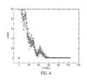
Fig. 4 shows an energy spectrum of a CsSr1-x Eu x I3 crystal, with x=0.1, under the same conditions as forFig. 1 . -
Fig. 5 shows a scintillation decay time spectrum of a CsSr1-x Eu x I3 crystal, with x=0.01; the spectrum was measured using 137Cs gamma-ray source (662 keV). -
Fig. 6 shows a scintillation decay time spectrum of a CsSr2(1-x)Eu2x I5 crystal, with x=0.01; the spectrum was measured using 137Cs gamma-ray source (662 keV). -
Fig. 7 shows energy spectra of two CsSr1-x Eu x I3 crystals, with x=0.07 and 0.08, respectively, under the same conditions as forFig. 1 . -
Fig. 8 shows a scintillation decay time spectrum of a CsSr1-x Eu x I3 crystal, with x=0.01; the spectrum was measured using 137Cs gamma-ray source (662 keV). -
Fig. 9 shows a scintillation decay time spectrum of a CsSr2(1-x)Eu2x I3 crystal, with x=0.01; the spectrum was measured using 137Cs gamma-ray source (662 keV). - Inorganic scintillators are commonly used in nuclear and high-energy physics research, medical imaging, homeland security, and geological exploration. These materials typically possess sufficient stopping power for detection, high luminosity, high spectral energy resolution at room temperature and short decay time.
- The viability of halide scintillators has been, and continues to be, investigated. For example, LaBr3 doped with Ce3+ is one of the best and most commonly used scintillators in security applications. As another example, SrI2 doped with Eu2+ exhibits a high light output of ~85,000 photons/MeV and ~4% energy resolution.
- The present disclosure relates to halide scintillator materials and more particularly discloses new iodide single-crystal scintillators and method of making them. In one arrangement, an iodide scintillator material is single-crystalline and has a composition of the formula:
ASr1-x Eu x I3,
A3Sr1-x Eu x I5
or
ASr2(1-x)Eu2x I5,
wherein A consists essentially of any alkali metal element (such as Li, Na K, Rb, Cs) or any combination thereof, and 0≤x≤ 1. More specific examples include CsSr1-x Eu x I3, Cs3Sr1-x Eu x I5 and CsSr2(1-x)Eu2x I5. - A further aspect of the present disclosure relates to a method of making chloride scintillator materials of the above-mentioned compositions. In one example, high-purity starting iodides (such as CsI, SrI2, EuI2 and rare-earth iodide(s)) are mixed and melted to synthesize a compound of the desired composition of the scintillator material. A single crystal of the scintillator material is then grown from the synthesized compound by the Bridgman method (or Vertical Gradient Freeze (VGF) method), in which a sealed ampoule containing the synthesized compound is transported from a hot zone to a cold zone through a controlled temperature gradient at a controlled speed to form a single-crystalline scintillator from molten synthesized compound.
- In another aspect of the present disclosure, the above-described scintillator materials are used in radiation detection by scintillation. For example, a radiation detector can include a scintillator described above for generating photons in response to the impinging radiation. The scintillator is optically coupled to a photon detector, such as a photomultiplier tube (PMT), arranged to receive the photons generated by the scintillator and adapted to generate a signal indicative of the photon generation. Such detectors can be used in applications such as imaging for security checking and medical diagnosis.
- In one arrangement, iodide single-crystals described above were grown. First, CsI, SrI2, EuI2 and additional rare earth iodides were prepared and loaded into a quartz ampoule in a glove box with pure nitrogen atmosphere. The starting materials were all anhydrous beads with at least 99.99% purity (available, e.g., from Sigma-Aldrich). The loaded ampoule was then connected to a vacuum system. The ampoule was sealed by a hydrogen torch after the vacuum inside the quartz ampoules was evacuated to at least 1×10⁻⁶ mBar. Vertical Gradient Freeze (VGF) technique was used to grow ASr1-x Eu x I3, A3Sr1-x Eu x I5 and ASr2(1-x)Eu2x I5 single crystals. The single crystals were grown in vacuum-sealed quartz ampoules of up to 1 inch diameter. A Mellen 24-zone Sunfire Electro-Dynamic Gradient furnace was used to create a vertically translating thermal gradient. The thermal gradient was electrically moved through the whole length of the crystal growth ampoule at a speed of 0.5-2 mm/hour (e.g., 1 mm/hour). Single crystal was grown from a capillary connected to the bottom of the ampoules. The capillary insures only one single crystal grain can propagate in to the ampoule body. After the growth was finished, the crystal was cooled down to room temperature at a rate of about 10°C/hour. The crystal was then cut, and ground and polished (as needed) in the glove box. Single crystals samples of about 10 mm across were obtained.
- Certain samples were characterized without polishing while for certain others, plates of about 1-3 mm in thickness were cut from the boules and polished using a set of sand papers and mineral oil. To identify the obtained phase, powder X-ray diffraction (XRD) analysis was carried out in air at room temperature. To minimize the effects of self-absorption, small samples (typically 1-2mm thick, 3mm×3mm) were selected for the optical characterization.
- Scintillation time profiles were recorded using the time-correlated single photon technique and a 137Cs gamma-ray source. Radioluminescence spectra were measured at room temperature (RT) under continuous irradiation from an X-ray generator (operating, e.g., at 35kV and 0.1mA). Light output measurements were carried out on samples covered in mineral oil and directly coupled to a photomultiplier tube (PMT) and covered with Teflon tape. A Hamamatsu 3177-50 PMT was used for absolute light output measurements. Gamma-ray energy spectra were recorded using a 137Cs source with a 10 µs shaping time. The integral quantum efficiency of the PMT according to the emission spectrum of the scintillators was used to calculate the number of photons per unit gamma ray energy. The energy resolution, at 662 keV was determined from the full-width at half-maximum (FWHM) of the 662 keV photopeak.
- According to certain aspects of the present disclosure, single crystals of the iodide materials suitable for scintillator applications were made, and their scintillation properties were measured and have demonstrated high performance under optical, X-ray, gamma ray excitations. These scintillators exhibit Eu2+ 5d-4f luminescence.
-
Figs. 1 to 4 shows the energy spectra for unpolished CsSr(1-x)Eu x I3, where x=0.01, 0.05, 0.075 and 0.1, respectively. The channel numbers are proportional to the relative light output of the sample. The relative light output (photo peak position) of the reference crystal BGO is 100 on this scale. The light output of these samples was at least about 40,000 photons/ MeV. -
Figs. 5 and6 show the scintillation time profiles for unpolished CsSr0.99Eu0.01I3 and CsSr1.98Eu0.02I5 samples, respectively. Both profiles were measured by a 137Cs source. The scintillation decay times for CsSr0.99Eu0.01I3 consist of two components: 429 ns for 20% and 1421 ns for 80%. The scintillation decay times for CsSr1.98Eu0.02I5 are 207 ns for 35% and 1,114 ns for 65%. -
Fig. 7 shows energy spectra of two polished CsSr1-x Eu x I3 crystals, with x=0.07 and 0.08, respectively, as compared to that of BGO. The absolute light yield is about twelve (12) times that of BGO for CsSr0.93Eu0.07I3 and about eight (8) times that of BGO for CsSr0.92Eu0.08I3. -
Fig. 8 shows a scintillation decay time spectrum of a polished CsSr1-x Eu x I3 crystal, with x=0.01; the spectrum was measured using 137Cs gamma-ray source (662 keV). The decay spectrum was fitted to a single exponential curve, with a decay time of about 1.7 µs. -
Fig. 9 shows a scintillation decay time spectrum of a polished CsSr2(1-x)Eu2x I3 crystal, with x=0.01; the spectrum was measured using 137Cs gamma-ray source (662 keV). - In aspect of the present disclosure, certain properties of certain iodide scintillator crystals disclosed above were measured as a function of composition. For example, light yield, energy resolution and scintillation decay times were measured as a function of composition for single-crystalline CsSr1-x Eu x I3 samples. The results are listed in Table I.
Table I Summary of scintillation properties for CsSr1-x Eu x I3 Composition light yield (ph/MeV) energy resolution at 662 keV Scintillation decay time (is) CsSr0.99Eu0.01I3 32000 9.0% 1.7 CsSr0.92Eu0.08I3 65000 5.9% 3.3 CsEuI3 24000 11.0% 3.4 - Thus, Eu-activated iodide scintillator crystals with excellent scintillation properties have been produced according to the present disclosure. Because many embodiments of the invention can be made without departing from the spirit and scope of the invention, the invention resides in the claims hereinafter appended.
Claims (14)
- A scintillator material comprising a single crystal having a composition of the formula
AM1-x Eu x I3,
A3M1-x Eu x I5,
or
AM2(1-x)Eu2x I5,
wherein:A consists essentially of any alkali metal element or any combination thereof,M consists essentially of Sr, Ca, Ba or any combination thereof, and0≤x≤1. - The scintillator material of claim 1, the single crystal having a composition of formula
ASr1-x Eu x I3,
A3Sr1-xEu x I5,
or
ASr2(1-x)Eu2x I5.
- The scintillator material of claim 2, the single crystal having a composition of formula
CsSr1-x Eu x I3,
Cs3Sr1-x Eu x I5,
or
CsSr2(1-x)Eu2x I5.
- The scintillator material of claim 1, wherein x is less than, or equal to, about 0.1.
- The scintillator material of claim 3, having a light output of at least about four times that of BGO when excited with a gamma-ray of 662 keV.
- The scintillator material of claim 5, having a light output of at least about eight times that of BGO when excited with a gamma-ray of 662 keV.
- The scintillator material of claim 6, having a light output of at least about twelve times that of BGO when excited with a gamma-ray of 662 keV.
- A method of making a scintillator material, the method comprising:synthesizing a compound having a composition of the formula
AM1-x Eu x I3,
A3M1-x Eu x I5,
or
AM2(1-x)Eu2x I5,
wherein:A consists essentially of any alkali metal element or any combination thereof,M consists essentially of Sr, Ca, Ba or any combination thereof,
and0≤x≤1;
growing a single crystal from the synthesized compound. - The method of claim 8, wherein the synthesizing step comprises synthesizing a compound having a formula of:
ASr1-x Eu x I3,
A3Sr1-x Eu x I5,
or
ASr2(1-x)Eu2x I5.
- The method of claim 8, wherein growing a single crystal comprises growing a single crystal from the synthesized compound using a Vertical Gradient Freeze method.
- The method of claim 8, wherein the synthesizing step comprises heating a mixture of a plurality of iodides above their respective melting temperatures.
- The method of claim 11, wherein the synthesizing step comprises heating a mixture of CsI, SrI2 and EuI2 above their respective melting temperatures.
- A radiation detector, comprising:a scintillator material of claim 1 adapted to generate photons in response to an impinging radiation; anda photon detector optically coupled to the scintillator material, arranged to receive the photons generated by the scintillator material and adapted to generate an electrical signal indicative of the photon generation.
- An imaging method, comprising:using at least one radiation detector of claim 13 to receive radiation from a plurality of radiation sources distributed in an object to be imaged and generate a plurality of signals indicative of the received radiation; andbased on the plurality of signals, deriving a special distribution of an attribute of the object.
Priority Applications (1)
| Application Number | Priority Date | Filing Date | Title |
|---|---|---|---|
| US14/314,393 US9453161B2 (en) | 2010-05-10 | 2014-06-25 | Chloride, bromide and iodide scintillators with europium doping |
Applications Claiming Priority (2)
| Application Number | Priority Date | Filing Date | Title |
|---|---|---|---|
| US33294510P | 2010-05-10 | 2010-05-10 | |
| US13/098,654 US8692203B1 (en) | 2010-05-10 | 2011-05-02 | Iodide scintillator for radiation detection |
Publications (3)
| Publication Number | Publication Date |
|---|---|
| EP2387040A2 true EP2387040A2 (en) | 2011-11-16 |
| EP2387040A3 EP2387040A3 (en) | 2012-07-18 |
| EP2387040B1 EP2387040B1 (en) | 2017-11-29 |
Family
ID=44587627
Family Applications (1)
| Application Number | Title | Priority Date | Filing Date |
|---|---|---|---|
| EP11165485.1A Active EP2387040B1 (en) | 2010-05-10 | 2011-05-10 | Iodide scintillator for radiation detection |
Country Status (3)
| Country | Link |
|---|---|
| US (1) | US8692203B1 (en) |
| EP (1) | EP2387040B1 (en) |
| CN (3) | CN106635020A (en) |
Cited By (6)
| Publication number | Priority date | Publication date | Assignee | Title |
|---|---|---|---|---|
| DE102012101199A1 (en) | 2011-02-15 | 2012-09-06 | University Of Tennessee Research Foundation | Composition useful e.g. as X-ray and gamma ray detector, comprises chemical composition of calcium europium compound or cesium europium compound |
| WO2015010055A1 (en) * | 2013-07-19 | 2015-01-22 | University Of Tennessee Research Foundation | Ternary metal halide scintillator |
| DE102014118239A1 (en) | 2014-06-25 | 2015-12-31 | University Of Tennessee Research Foundation | Chloride, bromide and iodide scintillators with europium doping |
| US9453161B2 (en) | 2010-05-10 | 2016-09-27 | University Of Tennessee Research Foundation | Chloride, bromide and iodide scintillators with europium doping |
| US10221355B2 (en) | 2013-07-19 | 2019-03-05 | University Of Tennessee Research Foundation | Ternary metal halide scintillators |
| US10838083B2 (en) | 2018-02-14 | 2020-11-17 | University Of Tennessee Research Foundation | Alkali and alkaline earth halides and methods thereof |
Families Citing this family (6)
| Publication number | Priority date | Publication date | Assignee | Title |
|---|---|---|---|---|
| US9053832B2 (en) | 2009-05-07 | 2015-06-09 | The Regents Of The University Of California | Lanthanide doped strontium-barium cesium halide scintillators |
| US10174244B2 (en) * | 2013-04-17 | 2019-01-08 | The Regents Of The University Of California | Doped halide scintillators |
| CN105778900B (en) * | 2014-12-24 | 2018-03-16 | 有研稀土新材料股份有限公司 | Inorganic scintillation material |
| CN106801254B (en) * | 2017-01-22 | 2019-10-01 | 山东大学 | A kind of CsSrI3The preparation method of scintillation crystal |
| CN112573905B (en) * | 2020-12-24 | 2023-01-13 | 中国科学院上海硅酸盐研究所 | Anion-doped garnet scintillator and preparation method and application thereof |
| CN120683615B (en) * | 2025-08-22 | 2025-11-04 | 江苏先进无机材料研究院 | An Eu-doped multi-component halide scintillator, its preparation method and application |
Family Cites Families (15)
| Publication number | Priority date | Publication date | Assignee | Title |
|---|---|---|---|---|
| JPS60135929A (en) * | 1983-12-23 | 1985-07-19 | Konishiroku Photo Ind Co Ltd | Reading method of radiation picture |
| US5882548A (en) * | 1997-05-08 | 1999-03-16 | International Business Machines Corporation | Luminescent organic-inorganic perovskites with a divalent rare earth metal halide framework |
| US6369391B1 (en) | 1999-05-02 | 2002-04-09 | Elgems Ltd. | Light output optimization |
| FR2855830B1 (en) * | 2003-06-05 | 2005-07-08 | Stichting Tech Wetenschapp | SCINTILLATION CRYSTALS OF THE RARE EARTH IODIDE TYPE |
| EP1516905A3 (en) * | 2003-09-22 | 2005-06-08 | Konica Minolta Medical & Graphic, Inc. | Radiation image conversion panel and preparation method thereof |
| US20050072937A1 (en) * | 2003-10-02 | 2005-04-07 | Konica Minolta Medical & Graphic, Inc. | Radiation image conversion panel and preparation method thereof |
| US7141794B2 (en) * | 2004-06-28 | 2006-11-28 | General Electric Company | Scintillator compositions, related processes, and articles of manufacture |
| US20060163538A1 (en) * | 2004-12-23 | 2006-07-27 | Gabi Schierning | Storage phosphor providing improved speed |
| US20060226368A1 (en) * | 2005-03-30 | 2006-10-12 | General Electric Company | Scintillator compositions based on lanthanide halides and alkali metals, and related methods and articles |
| CN101218319A (en) * | 2005-07-13 | 2008-07-09 | 柯尼卡美能达医疗印刷器材株式会社 | Precursor of halide-based luminous phosphor, halide-based luminous phosphor, radiographic image conversion plate, and method for producing the same |
| US20070036893A1 (en) * | 2005-08-12 | 2007-02-15 | Jean-Pierre Tahon | Method for reproducible manufacturing of storage phosphor plates |
| US20070131874A1 (en) * | 2005-12-12 | 2007-06-14 | General Electric Company | Scintillator materials which are useful for detecting radiation, and related methods and articles |
| US7655919B1 (en) * | 2007-11-09 | 2010-02-02 | Radiation Monitoring Devices, Inc. | Cesium and lithium-containing quaternary compound scintillators |
| US8119028B2 (en) * | 2007-11-14 | 2012-02-21 | Cree, Inc. | Cerium and europium doped single crystal phosphors |
| JPWO2010103917A1 (en) * | 2009-03-13 | 2012-09-13 | コニカミノルタエムジー株式会社 | Radiation detector |
-
2011
- 2011-05-02 US US13/098,654 patent/US8692203B1/en active Active
- 2011-05-10 CN CN201611174095.4A patent/CN106635020A/en active Pending
- 2011-05-10 CN CN2011101595472A patent/CN102277170A/en active Pending
- 2011-05-10 EP EP11165485.1A patent/EP2387040B1/en active Active
- 2011-05-10 CN CN201610017168.2A patent/CN105670627A/en active Pending
Cited By (10)
| Publication number | Priority date | Publication date | Assignee | Title |
|---|---|---|---|---|
| US8815119B2 (en) | 2010-05-10 | 2014-08-26 | University Of Tennessee Research Foundation | Chloride, bromide and iodide scintillators with europium doping |
| US9453161B2 (en) | 2010-05-10 | 2016-09-27 | University Of Tennessee Research Foundation | Chloride, bromide and iodide scintillators with europium doping |
| DE102012101199A1 (en) | 2011-02-15 | 2012-09-06 | University Of Tennessee Research Foundation | Composition useful e.g. as X-ray and gamma ray detector, comprises chemical composition of calcium europium compound or cesium europium compound |
| WO2015010055A1 (en) * | 2013-07-19 | 2015-01-22 | University Of Tennessee Research Foundation | Ternary metal halide scintillator |
| JP2016531170A (en) * | 2013-07-19 | 2016-10-06 | ユニバーシティ オブ テネシー リサーチ ファウンデーションUniversity Of Tennessee Research Foundation | Ternary metal halide scintillator |
| US9624429B2 (en) | 2013-07-19 | 2017-04-18 | University Of Tennessee Research Foundation | Ternary metal halide scintillators |
| US9695356B1 (en) | 2013-07-19 | 2017-07-04 | University Of Tennessee Research Foundation | Ternary metal halide scintillators |
| US10221355B2 (en) | 2013-07-19 | 2019-03-05 | University Of Tennessee Research Foundation | Ternary metal halide scintillators |
| DE102014118239A1 (en) | 2014-06-25 | 2015-12-31 | University Of Tennessee Research Foundation | Chloride, bromide and iodide scintillators with europium doping |
| US10838083B2 (en) | 2018-02-14 | 2020-11-17 | University Of Tennessee Research Foundation | Alkali and alkaline earth halides and methods thereof |
Also Published As
| Publication number | Publication date |
|---|---|
| CN102277170A (en) | 2011-12-14 |
| EP2387040A3 (en) | 2012-07-18 |
| US20140110588A1 (en) | 2014-04-24 |
| US8692203B1 (en) | 2014-04-08 |
| CN106635020A (en) | 2017-05-10 |
| CN105670627A (en) | 2016-06-15 |
| EP2387040B1 (en) | 2017-11-29 |
Similar Documents
| Publication | Publication Date | Title |
|---|---|---|
| EP2387040B1 (en) | Iodide scintillator for radiation detection | |
| EP2386618B1 (en) | Halide scintillator for radiation detection | |
| US8598530B2 (en) | Chloride scintillator for radiation detection | |
| US11360222B2 (en) | Lanthanide doped cesium barium halide scintillators | |
| US7141794B2 (en) | Scintillator compositions, related processes, and articles of manufacture | |
| USRE45930E1 (en) | Lanthanide doped strontium barium mixed halide scintillators | |
| CN104508192B (en) | Multi-doped lutetium-based oxyorthosilicate scintillators with improved optical properties | |
| Higgins et al. | Crystal growth of large diameter LaBr3: Ce and CeBr3 | |
| US20230235219A1 (en) | Low-dimensional perovskite-structured metal halide and preparation method and application thereof | |
| US7365333B1 (en) | LuxY(1−x)Xa3 scintillators | |
| US20080131347A1 (en) | Scintillation compositions and method of manufacture thereof | |
| Lam et al. | Crystal growth and scintillation performance of Cs2HfCl6 and Cs2HfCl4Br2 | |
| US9404036B2 (en) | Alkali metal and alkali earth metal gadolinium halide scintillators | |
| WO2010129926A1 (en) | Novel lanthanide doped barium mixed halide scintillators | |
| US7060982B2 (en) | Fluoride single crystal for detecting radiation, scintillator and radiation detector using the single crystal, and method for detecting radiation | |
| US20090146065A1 (en) | Scintillator materials based on lanthanide silicates or lanthanide phosphates, and related methods and articles | |
| Zhuravleva et al. | Crystal growth and scintillation properties of Cs 3 CeX 6 and CsCe 2 X 7 (X= Cl, Br) | |
| US8384035B2 (en) | Lanthanide doped barium phosphorous oxide scintillators | |
| US10174244B2 (en) | Doped halide scintillators | |
| Kantuptim | Pyrosilicate single crystals for ionizing radiation detection | |
| Hawrami | Fabrication of Low-Cost Large-Volume Ceramic A2HfX6 (A= Cs or Tl, X= Cl, Br, or I) Scintillators for Gamma Ray Detection (SBIR Phase I Final Technical Report) | |
| Roy et al. | Scintillation properties of K 2 LaBr 5: Ce 3+ crystals for gamma-ray spectroscopy |
Legal Events
| Date | Code | Title | Description |
|---|---|---|---|
| AK | Designated contracting states |
Kind code of ref document: A2 Designated state(s): AL AT BE BG CH CY CZ DE DK EE ES FI FR GB GR HR HU IE IS IT LI LT LU LV MC MK MT NL NO PL PT RO RS SE SI SK SM TR |
|
| AX | Request for extension of the european patent |
Extension state: BA ME |
|
| PUAI | Public reference made under article 153(3) epc to a published international application that has entered the european phase |
Free format text: ORIGINAL CODE: 0009012 |
|
| PUAL | Search report despatched |
Free format text: ORIGINAL CODE: 0009013 |
|
| AK | Designated contracting states |
Kind code of ref document: A3 Designated state(s): AL AT BE BG CH CY CZ DE DK EE ES FI FR GB GR HR HU IE IS IT LI LT LU LV MC MK MT NL NO PL PT RO RS SE SI SK SM TR |
|
| AX | Request for extension of the european patent |
Extension state: BA ME |
|
| RIC1 | Information provided on ipc code assigned before grant |
Ipc: G21K 4/00 20060101AFI20120614BHEP Ipc: C09K 11/77 20060101ALI20120614BHEP |
|
| 17P | Request for examination filed |
Effective date: 20130118 |
|
| 17Q | First examination report despatched |
Effective date: 20161014 |
|
| STAA | Information on the status of an ep patent application or granted ep patent |
Free format text: STATUS: EXAMINATION IS IN PROGRESS |
|
| RIC1 | Information provided on ipc code assigned before grant |
Ipc: G21K 4/00 20060101AFI20170519BHEP Ipc: C30B 11/00 20060101ALI20170519BHEP Ipc: C09K 11/77 20060101ALI20170519BHEP Ipc: G01T 1/20 20060101ALI20170519BHEP Ipc: G01T 3/06 20060101ALI20170519BHEP Ipc: C30B 29/12 20060101ALI20170519BHEP Ipc: G01T 1/202 20060101ALI20170519BHEP |
|
| GRAP | Despatch of communication of intention to grant a patent |
Free format text: ORIGINAL CODE: EPIDOSNIGR1 |
|
| STAA | Information on the status of an ep patent application or granted ep patent |
Free format text: STATUS: GRANT OF PATENT IS INTENDED |
|
| INTG | Intention to grant announced |
Effective date: 20170629 |
|
| RIN1 | Information on inventor provided before grant (corrected) |
Inventor name: SZUPRYCZYNSKI, PIOTR Inventor name: YANG, KAN, MR. Inventor name: MELCHER, CHARLES L., DR. Inventor name: ZHURAVLEVA, MARIYA |
|
| GRAS | Grant fee paid |
Free format text: ORIGINAL CODE: EPIDOSNIGR3 |
|
| GRAA | (expected) grant |
Free format text: ORIGINAL CODE: 0009210 |
|
| STAA | Information on the status of an ep patent application or granted ep patent |
Free format text: STATUS: THE PATENT HAS BEEN GRANTED |
|
| AK | Designated contracting states |
Kind code of ref document: B1 Designated state(s): AL AT BE BG CH CY CZ DE DK EE ES FI FR GB GR HR HU IE IS IT LI LT LU LV MC MK MT NL NO PL PT RO RS SE SI SK SM TR |
|
| REG | Reference to a national code |
Ref country code: CH Ref legal event code: EP |
|
| REG | Reference to a national code |
Ref country code: AT Ref legal event code: REF Ref document number: 951080 Country of ref document: AT Kind code of ref document: T Effective date: 20171215 |
|
| REG | Reference to a national code |
Ref country code: IE Ref legal event code: FG4D |
|
| REG | Reference to a national code |
Ref country code: DE Ref legal event code: R096 Ref document number: 602011043723 Country of ref document: DE |
|
| REG | Reference to a national code |
Ref country code: NL Ref legal event code: MP Effective date: 20171129 |
|
| REG | Reference to a national code |
Ref country code: LT Ref legal event code: MG4D |
|
| REG | Reference to a national code |
Ref country code: AT Ref legal event code: MK05 Ref document number: 951080 Country of ref document: AT Kind code of ref document: T Effective date: 20171129 |
|
| PG25 | Lapsed in a contracting state [announced via postgrant information from national office to epo] |
Ref country code: LT Free format text: LAPSE BECAUSE OF FAILURE TO SUBMIT A TRANSLATION OF THE DESCRIPTION OR TO PAY THE FEE WITHIN THE PRESCRIBED TIME-LIMIT Effective date: 20171129 Ref country code: FI Free format text: LAPSE BECAUSE OF FAILURE TO SUBMIT A TRANSLATION OF THE DESCRIPTION OR TO PAY THE FEE WITHIN THE PRESCRIBED TIME-LIMIT Effective date: 20171129 Ref country code: SE Free format text: LAPSE BECAUSE OF FAILURE TO SUBMIT A TRANSLATION OF THE DESCRIPTION OR TO PAY THE FEE WITHIN THE PRESCRIBED TIME-LIMIT Effective date: 20171129 Ref country code: ES Free format text: LAPSE BECAUSE OF FAILURE TO SUBMIT A TRANSLATION OF THE DESCRIPTION OR TO PAY THE FEE WITHIN THE PRESCRIBED TIME-LIMIT Effective date: 20171129 Ref country code: NO Free format text: LAPSE BECAUSE OF FAILURE TO SUBMIT A TRANSLATION OF THE DESCRIPTION OR TO PAY THE FEE WITHIN THE PRESCRIBED TIME-LIMIT Effective date: 20180228 |
|
| REG | Reference to a national code |
Ref country code: FR Ref legal event code: PLFP Year of fee payment: 8 |
|
| PG25 | Lapsed in a contracting state [announced via postgrant information from national office to epo] |
Ref country code: BG Free format text: LAPSE BECAUSE OF FAILURE TO SUBMIT A TRANSLATION OF THE DESCRIPTION OR TO PAY THE FEE WITHIN THE PRESCRIBED TIME-LIMIT Effective date: 20180228 Ref country code: AT Free format text: LAPSE BECAUSE OF FAILURE TO SUBMIT A TRANSLATION OF THE DESCRIPTION OR TO PAY THE FEE WITHIN THE PRESCRIBED TIME-LIMIT Effective date: 20171129 Ref country code: LV Free format text: LAPSE BECAUSE OF FAILURE TO SUBMIT A TRANSLATION OF THE DESCRIPTION OR TO PAY THE FEE WITHIN THE PRESCRIBED TIME-LIMIT Effective date: 20171129 Ref country code: HR Free format text: LAPSE BECAUSE OF FAILURE TO SUBMIT A TRANSLATION OF THE DESCRIPTION OR TO PAY THE FEE WITHIN THE PRESCRIBED TIME-LIMIT Effective date: 20171129 Ref country code: RS Free format text: LAPSE BECAUSE OF FAILURE TO SUBMIT A TRANSLATION OF THE DESCRIPTION OR TO PAY THE FEE WITHIN THE PRESCRIBED TIME-LIMIT Effective date: 20171129 Ref country code: GR Free format text: LAPSE BECAUSE OF FAILURE TO SUBMIT A TRANSLATION OF THE DESCRIPTION OR TO PAY THE FEE WITHIN THE PRESCRIBED TIME-LIMIT Effective date: 20180301 |
|
| PG25 | Lapsed in a contracting state [announced via postgrant information from national office to epo] |
Ref country code: NL Free format text: LAPSE BECAUSE OF FAILURE TO SUBMIT A TRANSLATION OF THE DESCRIPTION OR TO PAY THE FEE WITHIN THE PRESCRIBED TIME-LIMIT Effective date: 20171129 |
|
| PG25 | Lapsed in a contracting state [announced via postgrant information from national office to epo] |
Ref country code: DK Free format text: LAPSE BECAUSE OF FAILURE TO SUBMIT A TRANSLATION OF THE DESCRIPTION OR TO PAY THE FEE WITHIN THE PRESCRIBED TIME-LIMIT Effective date: 20171129 Ref country code: SK Free format text: LAPSE BECAUSE OF FAILURE TO SUBMIT A TRANSLATION OF THE DESCRIPTION OR TO PAY THE FEE WITHIN THE PRESCRIBED TIME-LIMIT Effective date: 20171129 Ref country code: CZ Free format text: LAPSE BECAUSE OF FAILURE TO SUBMIT A TRANSLATION OF THE DESCRIPTION OR TO PAY THE FEE WITHIN THE PRESCRIBED TIME-LIMIT Effective date: 20171129 Ref country code: EE Free format text: LAPSE BECAUSE OF FAILURE TO SUBMIT A TRANSLATION OF THE DESCRIPTION OR TO PAY THE FEE WITHIN THE PRESCRIBED TIME-LIMIT Effective date: 20171129 Ref country code: CY Free format text: LAPSE BECAUSE OF FAILURE TO SUBMIT A TRANSLATION OF THE DESCRIPTION OR TO PAY THE FEE WITHIN THE PRESCRIBED TIME-LIMIT Effective date: 20171129 |
|
| REG | Reference to a national code |
Ref country code: DE Ref legal event code: R097 Ref document number: 602011043723 Country of ref document: DE |
|
| PG25 | Lapsed in a contracting state [announced via postgrant information from national office to epo] |
Ref country code: PL Free format text: LAPSE BECAUSE OF FAILURE TO SUBMIT A TRANSLATION OF THE DESCRIPTION OR TO PAY THE FEE WITHIN THE PRESCRIBED TIME-LIMIT Effective date: 20171129 Ref country code: SM Free format text: LAPSE BECAUSE OF FAILURE TO SUBMIT A TRANSLATION OF THE DESCRIPTION OR TO PAY THE FEE WITHIN THE PRESCRIBED TIME-LIMIT Effective date: 20171129 Ref country code: IT Free format text: LAPSE BECAUSE OF FAILURE TO SUBMIT A TRANSLATION OF THE DESCRIPTION OR TO PAY THE FEE WITHIN THE PRESCRIBED TIME-LIMIT Effective date: 20171129 Ref country code: RO Free format text: LAPSE BECAUSE OF FAILURE TO SUBMIT A TRANSLATION OF THE DESCRIPTION OR TO PAY THE FEE WITHIN THE PRESCRIBED TIME-LIMIT Effective date: 20171129 |
|
| PLBE | No opposition filed within time limit |
Free format text: ORIGINAL CODE: 0009261 |
|
| STAA | Information on the status of an ep patent application or granted ep patent |
Free format text: STATUS: NO OPPOSITION FILED WITHIN TIME LIMIT |
|
| 26N | No opposition filed |
Effective date: 20180830 |
|
| PG25 | Lapsed in a contracting state [announced via postgrant information from national office to epo] |
Ref country code: SI Free format text: LAPSE BECAUSE OF FAILURE TO SUBMIT A TRANSLATION OF THE DESCRIPTION OR TO PAY THE FEE WITHIN THE PRESCRIBED TIME-LIMIT Effective date: 20171129 |
|
| REG | Reference to a national code |
Ref country code: CH Ref legal event code: PL |
|
| GBPC | Gb: european patent ceased through non-payment of renewal fee |
Effective date: 20180510 |
|
| REG | Reference to a national code |
Ref country code: BE Ref legal event code: MM Effective date: 20180531 |
|
| PG25 | Lapsed in a contracting state [announced via postgrant information from national office to epo] |
Ref country code: MC Free format text: LAPSE BECAUSE OF FAILURE TO SUBMIT A TRANSLATION OF THE DESCRIPTION OR TO PAY THE FEE WITHIN THE PRESCRIBED TIME-LIMIT Effective date: 20171129 |
|
| REG | Reference to a national code |
Ref country code: IE Ref legal event code: MM4A |
|
| PG25 | Lapsed in a contracting state [announced via postgrant information from national office to epo] |
Ref country code: CH Free format text: LAPSE BECAUSE OF NON-PAYMENT OF DUE FEES Effective date: 20180531 Ref country code: LI Free format text: LAPSE BECAUSE OF NON-PAYMENT OF DUE FEES Effective date: 20180531 |
|
| PG25 | Lapsed in a contracting state [announced via postgrant information from national office to epo] |
Ref country code: LU Free format text: LAPSE BECAUSE OF NON-PAYMENT OF DUE FEES Effective date: 20180510 |
|
| PG25 | Lapsed in a contracting state [announced via postgrant information from national office to epo] |
Ref country code: GB Free format text: LAPSE BECAUSE OF NON-PAYMENT OF DUE FEES Effective date: 20180510 Ref country code: IE Free format text: LAPSE BECAUSE OF NON-PAYMENT OF DUE FEES Effective date: 20180510 |
|
| PG25 | Lapsed in a contracting state [announced via postgrant information from national office to epo] |
Ref country code: BE Free format text: LAPSE BECAUSE OF NON-PAYMENT OF DUE FEES Effective date: 20180531 |
|
| PG25 | Lapsed in a contracting state [announced via postgrant information from national office to epo] |
Ref country code: MT Free format text: LAPSE BECAUSE OF NON-PAYMENT OF DUE FEES Effective date: 20180510 |
|
| PG25 | Lapsed in a contracting state [announced via postgrant information from national office to epo] |
Ref country code: TR Free format text: LAPSE BECAUSE OF FAILURE TO SUBMIT A TRANSLATION OF THE DESCRIPTION OR TO PAY THE FEE WITHIN THE PRESCRIBED TIME-LIMIT Effective date: 20171129 |
|
| PG25 | Lapsed in a contracting state [announced via postgrant information from national office to epo] |
Ref country code: PT Free format text: LAPSE BECAUSE OF FAILURE TO SUBMIT A TRANSLATION OF THE DESCRIPTION OR TO PAY THE FEE WITHIN THE PRESCRIBED TIME-LIMIT Effective date: 20171129 Ref country code: HU Free format text: LAPSE BECAUSE OF FAILURE TO SUBMIT A TRANSLATION OF THE DESCRIPTION OR TO PAY THE FEE WITHIN THE PRESCRIBED TIME-LIMIT; INVALID AB INITIO Effective date: 20110510 |
|
| PG25 | Lapsed in a contracting state [announced via postgrant information from national office to epo] |
Ref country code: MK Free format text: LAPSE BECAUSE OF NON-PAYMENT OF DUE FEES Effective date: 20171129 |
|
| PG25 | Lapsed in a contracting state [announced via postgrant information from national office to epo] |
Ref country code: AL Free format text: LAPSE BECAUSE OF FAILURE TO SUBMIT A TRANSLATION OF THE DESCRIPTION OR TO PAY THE FEE WITHIN THE PRESCRIBED TIME-LIMIT Effective date: 20171129 Ref country code: IS Free format text: LAPSE BECAUSE OF FAILURE TO SUBMIT A TRANSLATION OF THE DESCRIPTION OR TO PAY THE FEE WITHIN THE PRESCRIBED TIME-LIMIT Effective date: 20180329 |
|
| PGFP | Annual fee paid to national office [announced via postgrant information from national office to epo] |
Ref country code: FR Payment date: 20250516 Year of fee payment: 15 |
|
| PGFP | Annual fee paid to national office [announced via postgrant information from national office to epo] |
Ref country code: DE Payment date: 20250718 Year of fee payment: 15 |
|
| REG | Reference to a national code |
Ref country code: DE Ref legal event code: R082 Ref document number: 602011043723 Country of ref document: DE |