EP2387002A2 - Image processing apparatus, method, and storage medium - Google Patents
Image processing apparatus, method, and storage medium Download PDFInfo
- Publication number
- EP2387002A2 EP2387002A2 EP11165310A EP11165310A EP2387002A2 EP 2387002 A2 EP2387002 A2 EP 2387002A2 EP 11165310 A EP11165310 A EP 11165310A EP 11165310 A EP11165310 A EP 11165310A EP 2387002 A2 EP2387002 A2 EP 2387002A2
- Authority
- EP
- European Patent Office
- Prior art keywords
- detection
- video
- image
- unit
- superimposition
- Prior art date
- Legal status (The legal status is an assumption and is not a legal conclusion. Google has not performed a legal analysis and makes no representation as to the accuracy of the status listed.)
- Granted
Links
Images



Classifications
-
- G—PHYSICS
- G06—COMPUTING OR CALCULATING; COUNTING
- G06T—IMAGE DATA PROCESSING OR GENERATION, IN GENERAL
- G06T7/00—Image analysis
- G06T7/20—Analysis of motion
- G06T7/254—Analysis of motion involving subtraction of images
-
- G—PHYSICS
- G06—COMPUTING OR CALCULATING; COUNTING
- G06T—IMAGE DATA PROCESSING OR GENERATION, IN GENERAL
- G06T7/00—Image analysis
- G06T7/20—Analysis of motion
-
- G—PHYSICS
- G06—COMPUTING OR CALCULATING; COUNTING
- G06T—IMAGE DATA PROCESSING OR GENERATION, IN GENERAL
- G06T2207/00—Indexing scheme for image analysis or image enhancement
- G06T2207/10—Image acquisition modality
- G06T2207/10016—Video; Image sequence
-
- G—PHYSICS
- G06—COMPUTING OR CALCULATING; COUNTING
- G06T—IMAGE DATA PROCESSING OR GENERATION, IN GENERAL
- G06T2207/00—Indexing scheme for image analysis or image enhancement
- G06T2207/20—Special algorithmic details
- G06T2207/20081—Training; Learning
-
- G—PHYSICS
- G06—COMPUTING OR CALCULATING; COUNTING
- G06T—IMAGE DATA PROCESSING OR GENERATION, IN GENERAL
- G06T2207/00—Indexing scheme for image analysis or image enhancement
- G06T2207/30—Subject of image; Context of image processing
- G06T2207/30232—Surveillance
-
- G—PHYSICS
- G08—SIGNALLING
- G08B—SIGNALLING SYSTEMS, e.g. PERSONAL CALLING SYSTEMS; ORDER TELEGRAPHS; ALARM SYSTEMS
- G08B13/00—Burglar, theft or intruder alarms
- G08B13/18—Actuation by interference with heat, light, or radiation of shorter wavelength; Actuation by intruding sources of heat, light, or radiation of shorter wavelength
- G08B13/189—Actuation by interference with heat, light, or radiation of shorter wavelength; Actuation by intruding sources of heat, light, or radiation of shorter wavelength using passive radiation detection systems
- G08B13/194—Actuation by interference with heat, light, or radiation of shorter wavelength; Actuation by intruding sources of heat, light, or radiation of shorter wavelength using passive radiation detection systems using image scanning and comparing systems
- G08B13/196—Actuation by interference with heat, light, or radiation of shorter wavelength; Actuation by intruding sources of heat, light, or radiation of shorter wavelength using passive radiation detection systems using image scanning and comparing systems using television cameras
- G08B13/19602—Image analysis to detect motion of the intruder, e.g. by frame subtraction
Definitions
- the present invention relates to an image processing apparatus for analyzing changes in a video through image processing.
- a known conventional imaging system detects changes in a video captured by a camera.
- a user needs to preset parameters for performing detection processing, such as a screen area subjected to detection processing, a position and size of an object to be detected in an area under detection, and a sensitivity of image processing. These parameters are set according to the position, size, color of the object to be detected, surrounding circumstances, and image-capturing conditions of the camera.
- parameters for performing detection processing are set in the following way.
- a user captures the motion of an object to be detected and surrounding circumstances in advance, and stores the captured video in a storage unit in an operation terminal via a camera server. Then, the user sets parameters for detection processing while playing back the video stored in the storage unit in the operation terminal (for example, as discussed in Japanese Patent Application Laid-Open No. 2004-248090 ).
- a range subjected to detection processing is specified in a video captured by a camera.
- a user draws a graphic pattern on a display, on which the video is displayed, to set a detection range, and determines a result of range setting on the display (for example, as discussed in Japanese Patent Application Laid-Open No. 2008-16898 ).
- the present invention is directed to an image processing apparatus which requires less manpower and operation necessary to set parameters for performing detection processing than conventional imaging systems.
- an information processing apparatus as specified in claims 1 to 6.
- a setting apparatus as specified in clams 7 to 10.
- a method for processing an image as specified in clams 11 there is provided a method by a setting apparatus as specified in clams 12.
- a computer-readable storage medium as specified in clams 13.
- the image processing apparatus When setting parameters for performing processing for detecting changes in a video, the image processing apparatus according to the present invention superimposes an image onto a video within a range subjected to detection processing to demonstrate a state of an object to be detected. Therefore, it is not necessary that a person goes to a camera and move the object to be detected to produce a state of the object to be detected. This enables reducing manpower and operation necessary to set parameters for performing detection processing.
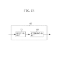
- Figs. 1A and 1B are block diagrams illustrating a configuration of an image processing apparatus.
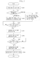
- Fig. 2 is a flow chart illustrating an operation of the image processing apparatus.
- Figs. 3A and 3B illustrate exemplary images superimposed by a superimposition unit of the image processing apparatus.
- Fig. 4 is a block diagram illustrating a configuration of a setting apparatus.
- Fig. 5 illustrates a setting screen of the setting apparatus.
- Figs. 6A and 6B are flow charts illustrating operations of the setting apparatus.
- Figs. 7A, 7B, and 7C illustrate states of a window displayed on the setting apparatus when performing verification.
- Fig. 1A is a block diagram illustrating a configuration of the image processing apparatus according to the first exemplary embodiment of the present invention.
- an image processing apparatus 100 Upon reception of an image, an image processing apparatus 100 outputs a compressed image and an analysis result of the input image.
- An acquisition unit 110 captures successive images as a video from an imaging apparatus 180 such as a video camera and a video recorder connected to the image processing apparatus 100.
- the acquisition unit 110 performs analog/digital (A/D) conversion and size conversion according to an instruction from a control unit 160 (described below), and outputs the video to a superimposition unit 120.
- the acquisition unit 110 achieves a function of acquiring a video in this way.
- the superimposition unit 120 superimposes an image onto the video acquired by the acquisition unit 110.
- the image to be superimposed onto the video is, for example, a character string indicating time information, a polygon or ellipse filled with a certain color, an image separately captured and stored, or a computer graphics image.
- the superimposition unit 120 may be configured by an existing drawing function such as a superimposition function of superimposing a character or graphic pattern onto an image, and a privacy mask function of superimposing a mask image onto a predetermined image for privacy protection.
- the superimposition unit 120 superimposes onto a video an image corresponding to the size of an object that is to be detected as emerging by a detection unit 131 (described below) in a preset area (hereinafter referred to as detection area) subjected to object detection by the detection unit 131.
- the superimposition unit 120 transmits the video having the image superimposed thereon to an analysis unit 130 and a compression unit 150.
- the compression unit 150 compresses the image based on a compression method and a compression rate specified by an instruction from the control unit 160 (described below), and outputs the compressed image to the outside of the image processing apparatus 100 via an interface (I/F) unit 140.
- the compression method is based on standards Motion JPEG, MPEG4, H.264, and JPEG.
- the analysis unit 130 detects the emergence of an object in the preset area on the image by using the inter-frame difference method or background difference method, and determines the state of the object. As illustrated in Fig. 1B , the analysis unit 130 includes the detection unit 131 and a determination unit 132.
- the detection unit 131 detects the emergence of an object in a video in the detection area set on the video acquired by the acquisition unit 110. Based on a result of detection by the detection unit 131, the determination unit 132 determines the state of the object in the video in the detection area. In other words, the determination unit 132 judges the state of the object in the video in the detection area based on a result of detection by the detection unit 131.
- An exemplary object state "abandoning” is a state where an object emerges in the detection area and remains still at the same position for a preset duration or longer.
- Another exemplary object state “removing” is a state where the object under monitoring is removed and then a new object, such as a wall or floor surface that has been covered by the object under monitoring, emerges and remains still for a preset duration or longer.
- the detection unit 131 detects the emergence of an object based on the inter-frame difference method and the background difference method. These techniques obtain a difference, for example, in luminance between frames and recognizes as an emerging object an area having a difference equal to or larger than a preset threshold value.
- the determination unit 132 determines that the object is in the "abandoning" state. In a case where an object in the detection area is removed and the detection unit 131 detects that a new object that has been covered by the object emerges, the determination unit 132 determines that the object is in the "removing" state.
- object detection is achieved by obtaining a difference in luminance between frames, and an area having a difference exceeding a preset threshold value is recognized as an emerging object. Therefore, even when there is actually no object emerging in the video, giving an artificial difference in luminance to a certain portion in the video enables the portion to be detected as an object.
- the present exemplary embodiment uses this technique to perform verification of the object state analysis.
- the control unit 160 instructs the superimposition unit 120 to superimpose a graphic pattern equivalent to an emerging object onto an input image to generate a difference in luminance.
- the control unit 160 instructs the analysis unit 130 to detect the difference as the "abandoning" or "removing” state.
- Various settings stored in a storage unit 170 are used as conditions for detecting the "abandoning" or "removing” state.
- the analysis unit 130 determines whether the video containing the image superimposed by the superimposition unit 120 satisfies the conditions stored in the storage unit 170.
- the present exemplary embodiment will be described below based on a case where the analysis unit 130 analyzes "abandoning" and "removing", the present invention is not limited thereto but may be based on any function of detecting an emerging object in a set area and analyzing the state of the object. For example, the present invention may analyze that an object under monitoring disappears for a predetermined duration because a camera is covered by a cloth or paint.
- the image processing apparatus 100 outputs an analysis result via the I/F unit 140.
- the storage unit 170 stores operation settings for the acquisition unit 110, the superimposition unit 120, the analysis unit 130, and the compression unit 150.
- the acquisition unit 110, the superimposition unit 120, the analysis unit 130, and the compression unit 150 hold respective operation settings.
- the operation settings for the acquisition unit 110 include, for example, settings of a conversion magnification and a size after conversion in size conversion of the acquired image.
- the operation settings for the superimposition unit 120 include, for example, settings of a shape, size, and range of a graphic pattern to be superimposed onto the input image, and a color and a pause duration of the graphic pattern to be superimposed thereon.
- a graphic pattern is kept superimposed onto frames up to a frame for t seconds.
- a black image may be generally superimposed, a sufficient difference in luminance may not be obtained depending on a situation such as capturing a video outdoors during the night. Therefore, a color which is significantly different from the color (for example, opponent color) of the object may be set as the color of the image to be superimposed to ensure detection of abandoning.
- a black graphic pattern when detecting "removing" of an object, a black graphic pattern may be generally superimposed.
- the operation settings for the analysis unit 130 include, for example, settings of an object state analysis type ("abandoning” and "removing"), a screen area subjected to object detection, a size, a pause duration of an object under monitoring, and a detection sensitivity.
- the operation settings are not limited thereto. Further, not all of the above operation settings need to be set.
- the pause duration refers to a time interval during which an object emerges in the detection area and remains still.
- the determination unit 132 of the analysis unit 130 determines the occurrence of "abandoning" or "removing.”
- the detection sensitivity will be described below.
- the detection unit 131 of the analysis unit 130 compares a difference in luminance between pixels at the same pixel position in adj acent video frames. When the difference is equal to or larger than the set detection sensitivity, the detection unit 131 of the analysis unit 130 determines that the relevant pixel has changed.
- the operation settings for the analysis unit 130 are used by the analysis unit 130 as conditions for detecting the emergence of an object in the video in the detection area and determining the object state.
- the operation settings for the compression unit 150 include, for example, settings of a compression method and a compression rate of an image input to the compression unit 150.
- the control unit 160 receives an instruction from a user terminal via the I/F unit 140, controls the operations of the acquisition unit 110, the superimposition unit 120, the analysis unit 130, and the compression unit 150, and returns a response to the user. These control operations are performed by a processor and a memory included in the control unit 160.
- the processor included in the control unit 160 is a computer which reads a program from the memory included therein and then executes it.
- the memory included in the control unit 160 is a recording medium storing the program so as to be read by the processor. The program will be described below with reference to Fig. 2 .
- the instruction for verifying the operation of the analysis unit 130 is an instruction to instruct the image processing apparatus 100 to verify whether the analysis unit 130 detects the "abandoning" and "removing” states based on the operation settings stored in the storage unit 170.
- the control unit 160 Upon reception of the instruction for verifying the operation of the analysis unit 130, the control unit 160 performs control derived from the settings for the analysis unit 130 over the superimposition unit 120.
- the instruction for holding settings is an instruction to instruct the image processing apparatus 100 to hold the operation settings for the acquisition unit 110, the superimposition unit 120, the analysis unit 130, and the compression unit 150.
- the control unit 160 Upon reception of the instruction for holding settings, the control unit 160 stores in the storage unit 170 the operation settings for the acquisition unit 110, the superimposition unit 120, the analysis unit 130, and the compression unit 150.
- the stored operation settings are used as default operations for each unit to be performed when no control instruction is received from the user.
- the I/F unit 140 is connected with the user terminal via a network (not illustrated) to exchange information between the image processing apparatus 100 and the user and between the image processing apparatus 100 and a setting apparatus (described below) which sets various operation settings for each unit of the image processing apparatus 100.
- the I/F unit 140 transfers a control instruction from the user to the control unit 160, and returns to the user an analysis result from the analysis unit 130, compressed data from the compression unit 150, and a response from the control unit 160.
- FIG. 2 illustrates procedures of the program executed by the processor included in the control unit 160 when verifying the operation of the analysis unit 130.
- step S200 upon reception of the instruction for verifying the operation of the analysis unit 130 from the user terminal, the control unit 160 reads the settings for the analysis unit 130 from the storage unit 170.
- control unit 160 reads settings such as an object state analysis type ("abandoning” and "removing”), a screen area subjected to object detection, a size of an object under monitoring, and a pause duration until a relevant state is determined.
- an object state analysis type (“abandoning” and "removing”
- a screen area subjected to object detection a screen area subjected to object detection
- a size of an object under monitoring a size of an object under monitoring
- pause duration until a relevant state is determined.
- step S201 the control unit 160 determines the state ("abandoning” or "removing") from the settings read from the storage unit 170.
- the processing proceeds to step S202 or S203 corresponding to the detected state to set respective setting values to the analysis unit 130.
- step S202 the control unit 160 sets the superimposition unit 120 to superimpose an image corresponding to the size and color of the object subjected to detection of abandoning onto the video in the detection area. Specifically, the control unit 160 sets a position in the detection area read from the storage unit 170 as a position at which the image is to be superimposed, and sets a size read from the storage unit 170 as the size and color of the image to be superimposed.
- step S203 the control unit 160 sets the superimposition unit 120 to superimpose an image corresponding to the size of the detection area onto the video in the detection area. Specifically, the control unit 160 sets a size of the detection area as the position and size at which the image is to be superimposed, and sets a color read from the storage unit 170 as the color of the image to be superimposed.
- step S204 after setting values of the image to be superimposed are determined, the control unit 160 determines whether verification is possible. For example, verification cannot be started before the analysis unit 130 has generated a background image. The control unit 160 inquires of the analysis unit 130 whether the analysis unit 130 is activated.
- control unit 160 may instruct the analysis unit 130 to be activated and wait until the analysis unit 130 generates a background image.
- the control unit 160 may wait until the analysis unit 130 generates a background image after the user instructs the analysis unit 130 to be activated.
- the user instructs the analysis unit 130 to be activated using a start analysis button which is displayed on a display unit of the setting apparatus.
- the analysis unit 130 may have already been activated when starting the verification process shown in Figure 2 .
- object detection is achieved by obtaining a difference in luminance between frames, and an area having a difference exceeding a preset threshold value is recognized as an emerging object. Therefore, when an actual object has already emerged in the detection area at the time of verification, the analysis unit 130 cannot distinguish between the image superimposed by the superimposition unit 120 and the actual object. Therefore, while the detection unit 131 is detecting whether an object has emerged in the video in the detection area, the superimposition unit 120 does not start superimposing the image. Before starting verification, the detection unit 131 can determine whether an object has emerged in the detection area from a result of analysis by the analysis unit 130.
- step S204 When verification can be started (YES in step S204), the processing proceeds to step S205.
- step S205 the control unit 160 instructs the analysis unit 130 to start analyzing an image input from the superimposition unit 120.
- step S206 the control unit 160 controls the superimposition unit 120 to superimpose the image onto the video input from the acquisition unit 110 based on the setting values determined in step S202 or S203.
- the image to be superimposed onto the video depends on the function of the superimposition unit 120.
- the superimposition unit 120 when the superimposition unit 120 is configured by the privacy mask function, it draws a polygon or circle filled with a certain color. When the superimposition unit 120 is configured by the superimposition function, it superimposes a character string according to the drawing position and shape determined by the drawing parameters.
- Figs. 3A and 3B each illustrate exemplary superimposition of an image.
- Fig. 3A illustrates superimposition of a polygon 310 by using the privacy mask function in the case of the "abandoning" state.
- Fig. 3B illustrates superimposition of a character string 330 by using the superimposition function in the case of the "removing" state.
- a frame 300 is illustrated for description but not actually drawn.
- step S207 after the superimposition unit 120 starts superimposing an image, the control unit 160 determines whether the pause duration of the object to be superimposed read in step S200 has elapsed. When the pause duration has elapsed (YES in step S207), the processing proceeds to step S208. In step S208, the control unit 160 instructs the superimposition unit 120 to end superimposing the image.
- step S209 the control unit 160 controls the analysis unit 130 to notify to the user terminal via the I/F unit 140 an analysis result of the video having the image superimposed thereon by the superimposition unit 120.
- the control unit 160 controls the operations of the superimposition unit 120 and the analysis unit 130 in this way.
- the image processing apparatus 100 and the imaging apparatus 180 are independent apparatuses in the present exemplary embodiment, the image processing apparatus 100 may be integrated with the video camera or video recorder, and receive from the acquisition unit 110 successive images captured by any of such imaging apparatuses.
- the video camera may be a network camera located on a remote site, which enables remote video observation via a network.
- the image processing apparatus 100 enables verifying the function of analyzing object state transition through image processing without moving the actual object under monitoring. Therefore, the image processing apparatus 100 eliminates the need of operation on a video capturing site, thus reducing manpower and time required for verification.
- the superimposition unit 120 can be achieved by the superimposition function and the privacy mask function of the monitoring camera, enabling configuring an image processing apparatus at lower cost than a case where these functions are separately implemented.
- a second exemplary embodiment will be described below centering on a setting apparatus which sets various setting values to the image processing apparatus 100 described in the first exemplary embodiment and instructs the image processing apparatus 100 to detect the emergence of an object via the detection unit 131.
- FIG. 4 is a block diagram illustrating a configuration of the setting apparatus according to the second exemplary embodiment of the present invention.
- a setting apparatus 400 is a terminal which receives settings and instructions from the user and outputs instructions to an image processing apparatus performing object state analysis, for example, the image processing apparatus 100 according to the first exemplary embodiment of the present invention.
- the object state analysis refers to, for example, analyzing whether an object is in the "abandoning" or "removing" state in an input video.
- the I/F unit 410 is an interface between the setting apparatus 400 according to the second exemplary embodiment and the image processing apparatus 100 performing object state analysis.
- the I/F unit 410 outputs to the setting apparatus 400 via a network (not illustrated) user-input settings and instructions related to verification of object state analysis as settings and instructions for functions of the image processing apparatus 100 performing object state analysis.
- An analysis setting control unit 420 determines an end of input of settings and instructions related to object state analysis by an analysis area setting unit 430 and an analysis parameter setting unit 440 (described below), converts them into settings and instructions suitable for the image processing apparatus 100 performing object state analysis, and outputs them to the outside of the setting apparatus 400 via the I/F unit 410.
- the settings related to object state analysis include, for example, settings of an object state analysis type, a size range of the object subjected to object state analysis, and a pause duration of the object until the occurrence of an object state transition is determined.
- the instructions related to object state analysis include, for example, an instruction for completing settings for object state analysis and then transmitting the settings to the image processing apparatus 100 performing object state analysis, and an instruction for ending the operation of the setting apparatus 400.
- control operations are performed by a processor and a memory included in the analysis setting control unit 420.
- the processor included in the analysis setting control unit 420 is a computer which reads a program from the memory included therein and then executes it.
- the memory included in the analysis setting control unit 420 is a recording medium storing the program so as to be read by the processor.
- the program will be described below with reference to Fig. 6A .
- the analysis setting control unit 420 may be integrated with a verification control unit 450 (described below).
- the analysis area setting unit 430 provides a user interface for enabling the user to set a screen area subjected to object state analysis.
- the analysis parameter setting unit 440 provides a user interface for enabling the user to set parameters related to object state analysis.
- the parameters related to the object state analysis include, for example, a parameter related to a size range of the object subjected to object state analysis, and a parameter related to a pause duration of the object until the occurrence of an object state transition is determined.
- the verification control unit 450 determines an end of input of settings and instructions related to verification of object state analysis by a superimposition setting unit 460 and a verification parameter setting unit 470, converts them into settings and instructions suitable for the image processing apparatus 100 performing object state analysis, and outputs them to the outside of the setting apparatus 400 via the I/F unit 410.
- the settings related to verification of object state analysis include, for example, settings of an analysis area, a shape, size, and range of a graphic pattern to be superimposed as a pseudo object for verification, a color and a pause duration of the graphic pattern to be superimposed, and a selection of object state analysis for verification.
- the instructions related to verification of object state analysis include, for example, an instruction for completing settings for verification of object state analysis and then transmitting the settings to the image processing apparatus 100 performing object state analysis, and an instruction for detecting the emergence of an object based on the set conditions.
- instructions related to verification of object state analysis perform instruction to superimpose an image corresponding to the size of the object to be detected when emerging onto the video in the detection area as a pseudo object for verification, to output the resultant video to the detection unit 131 of the image processing apparatus 100, and to detect the emergence of the object.
- control operations are performed by a processor and a memory included in the verification control unit 450.
- the processor included in the verification control unit 450 is a computer which reads a program from the memory included therein and then executes it.
- the memory included in the verification control unit 450 is a recording medium storing the program so as to be read by the processor.
- the program will be described below with reference to Fig. 6B .
- the verification control unit 450 may be integrated with the analysis setting control unit 420.
- the superimposition setting unit 460 is a user interface for enabling the user to set a size, shape, superimposing position, and range of an image to be superimposed by the superimposition unit 120 of the image processing apparatus 100 performing object state analysis for verification of object state analysis.
- the verification parameter setting unit 470 is a user interface for enabling the user to set parameters for verification of object state analysis.
- the parameters for verification of object state analysis include, for example, a parameter related to a color and pause duration of an image to be superimposed.
- the user uses a switching unit 480 to instruct the image processing apparatus 100 connected with the setting apparatus 400 to perform object state analysis or verification of object sate analysis.
- the verification of object state analysis refers to verifying whether, when the image processing apparatus 100 performing object state analysis actually performs object state analysis based on the conditions set in the verification control unit 450, a desired object state can be detected.
- the setting apparatus 400 includes a display unit 495 which displays a setting screen 500 for performing setting for instructing the detection unit 131 of the image processing apparatus 100 (described in the first exemplary embodiment) to detect the emergence of an object.
- the setting screen 500 displayed on the display unit 495 serves as a graphical user interface (hereinafter referred to as GUI).
- the setting apparatus 400 includes a display control unit 490 which instructs the display unit 495 to display the setting screen 500.
- the setting screen 500 is displayed by a processor and a memory included in the display control unit 490.
- the processor included in the display control unit 490 is a computer which reads a program from the memory included therein and then executes it.
- the memory included in the display control unit 490 is a recording medium storing the program so as to be read by the processor.
- Radio buttons 505 are used to switch a target setting between object state analysis and verification of object state analysis. Depending on the setting of the radio buttons 505, the switching unit 480 selects whether the image processing apparatus 100 will perform object state analysis or verification of object state analysis.
- a graphic pattern input field 510 is used to set a screen area subjected to object state analysis (hereinafter this area is referred to as analysis area) and set a graphic pattern for verification of object state analysis.
- the target setting is selected according to the setting of the radio buttons 505. Specifically, when the radio button 505 for object state analysis is selected, the user can set an analysis area in the graphic pattern input field 510.
- the radio button 505 for verification of object state analysis when the radio button 505 for verification of object state analysis is selected, the user can set an image or a pseudo object in the graphic pattern input field 510.
- the set image or pseudo object is superimposed by the image processing apparatus 100 performing object state analysis for verification of object state analysis.
- a drawing tool selection palette 525 is used to select drawing tools (rectangle, ellipse, straight line, etc) and set a position and shape of the analysis area or pseudo object in the graphic pattern input field 510.
- a polygon frame 515 is an exemplary analysis area, and a pseudo object 520 is an exemplary image to be superimposed.
- the analysis area setting unit 430 sets a screen area subjected to object state analysis according to an input from the drawing tool selection palette 525.
- the superimposition setting unit 460 sets a size, shape, superimposing position, and range of an image to be superimposed according to an input from the drawing tool selection palette 525.
- the drawing tool selection palette 525 functions as a specification unit for specifying an image corresponding to the size of the object to be detected when emerging by the detection unit 131 of the image processing apparatus 100 according to the first exemplary embodiment.
- a parameter input field 530 is used to input parameters for verification of object state analysis. Referring to Fig. 5 , the user sets RGB values to the parameter input field 530 to specify the color of a graphic pattern to be drawn in the graphic pattern input field 510 by using the drawing tool selection palette 525.
- the user can adjust the color of the graphic pattern to be input by using the parameter input field 530.
- the user can verify what object color enables object state analysis.
- the user may set a pause duration of the graphic pattern input by using the parameter input field 530.
- the user can verify object state analysis using a pause duration of the input graphic pattern as required.
- the user can verify what pause duration enables object state analysis, during which the object to be detected remains still.
- the parameters input from the parameter input field 530 are not limited to parameters related to a color and pause duration of the input graphic pattern.
- the verification parameter setting unit 470 sets parameters for verification of object state analysis according to inputs from the parameter input field 530.
- the user uses an END button 535 to give an instruction to end the operation of the setting apparatus 400.
- the user uses a type selection button 540 to select a type of object state analysis, "ABANDONING” or "REMOVING.”
- the user uses an object size input field 545 to specify a size range of an object subjected to object state analysis.
- the user uses a pause duration input field 550 to specify a duration during which the object subjected to object state analysis remains still until the occurrence of an object state transition ("abandoning" or "removing") is determined.
- the analysis parameter setting unit 440 sets parameters related to object state analysis according to inputs from the object size input field 545 and the pause duration input field 550.
- a store settings button 555 instructs the setting apparatus 400 to complete the settings of object state analysis, and then transmit the settings to the image processing apparatus 100 performing object state analysis.
- a start verification button 560 instructs the setting apparatus 400 to complete settings for verification of object state analysis, and then transmit the settings to the image processing apparatus 100 performing object state analysis, to instruct the image processing apparatus 100 to start verification.
- the start verification button 560 functions as a starting unit for instructing the superimposition unit 120 of the image processing apparatus 100 according to the first exemplary embodiment to start superimposing the image specified by the drawing tool selection palette 525 onto the video in the detection area and then outputting the resultant video to the detection unit 131.
- Fig. 6A illustrates a procedure of the program executed by the processor included in the analysis setting control unit 420.
- Fig. 6B illustrates a procedure of the program executed by the processor included in the verification control unit 450.
- step S600 after the setting apparatus 400 is activated, the analysis setting control unit 420 determines whether the analysis area setting unit 430 receives setting of a screen area subjected to object state analysis and, when a relevant setting is input, performs necessary input processing such as conversion into internal values.
- step S601 the analysis setting control unit 420 further determines whether the analysis parameter setting unit 440 receives an analysis parameter and, when a relevant setting is input, performs necessary input processing such as conversion into internal values.
- the analysis setting control unit 420 repeats the above-mentioned processing until the user completes the setting process. Specifically, in step S602, the analysis setting control unit 420 determines whether, for example, the user presses the store settings button 555.
- step S603 the analysis setting control unit 420 transmits via the I/F unit 410 the settings to the image processing apparatus 100 performing object state analysis so as to be stored as setting values. Then, the analysis setting control unit 420 enables an interface related to verification setting.
- step S604 the analysis setting control unit 420 determines whether the user gives an instruction to end the setting process, for example, the user presses the END button 535. When the user gives an instruction to end the setting process (YES in step S604), the processing ends.
- step S605 the analysis setting control unit 420 instructs the verification control unit 450 to determine whether the target setting is object state analysis or verification of object state analysis.
- step S606 upon reception of the instruction from the analysis setting control unit 420, the verification control unit 450 checks the setting of the radio buttons 505 to determine whether the target setting is object state analysis or verification of object state analysis.
- step S606 the processing proceeds to step S607.
- step S607 the verification control unit 450 disables the interface related to the verification setting. Then, the processing returns to step S600.
- step S600 the verification control unit 450 instructs the analysis setting control unit 420 to input the setting of object state analysis.
- step S608 the verification control unit 450 determines whether the superimposition setting unit 460 receives a setting of the shape of a graphic pattern to be superimposed and, when a relevant setting is input, performs necessary input processing such as conversion into internal values. Then, the verification control unit 450 repeats the above-mentioned processing until the user completes the setting process. Specifically, in step S609, the verification control unit 450 determines whether, for example, the user presses the start verification button 560.
- step S610 the verification control unit 450 transmits via the I/F unit 410 the settings to the image processing apparatus 100 performing object state analysis as an image superimposition instruction. Then, the image processing apparatus 100 connected to the setting apparatus 400 starts verification by superimposing a graphic pattern (pseudo object). Upon completion of superimposition, the processing returns to step S606. The verification control unit 450 repeats processing from step S606.
- a display window 600 displays an image output from the image processing apparatus 100.
- the display window 600 is displayed on the display unit 495 of the setting apparatus 400.
- a frame 515 indicating an analysis area is displayed in the display window 600, as illustrated in Fig. 7A .
- the frame 515 does not necessarily need to be displayed.
- the display window 600 displays a state where the pseudo object 520 set in the setting apparatus 400 is superimposed onto a captured image by the superimposition unit 120 of the image processing apparatus 100.
- the display window 600 displays a state where the image output from the superimposition unit 120 is analyzed by the analysis unit 130 and then detected as an object state transition.
- the display window 600 displays a thick frame 610 around the detected object.
- the display window 600 also displays a message 615 to indicate that an object state transition is detected.
- Fig. 7C illustrates a state where the object with object state transition is enclosed by the thick frame 610, the frame is not limited thereto but may be a color frame.
- the message 615 does not necessarily need to be displayed.
- the image processing apparatus 100 may notify the user of an E-mail message indicating the detection of an object state transition.
- the image processing system enables verifying the detection of object state transition.
- both apparatuses may be integrated as one apparatus.
- the setting apparatus 400 enables verifying the function of analyzing object state transition through image processing while changing a graphic pattern (pseudo object) in diverse ways.
- the setting apparatus 400 eliminates the need of preparing a number of actual objects under monitoring. It enables repeating verification while immediately changing analysis settings even when state transition cannot be analyzed, thus reducing manpower and time required for extensive verification.
- aspects of the present invention can also be realized by a computer of a system or apparatus (or devices such as a CPU or MPU) that reads out and executes a program recorded on a memory device to perform the functions of the above-described embodiments, and by a method, the steps of which are performed by a computer of a system or apparatus by, for example, reading out and executing a program recorded on a memory device to perform the functions of the above-described embodiments.
- the program is provided to the computer for example via a network or from a recording medium of various types serving as the memory device (e.g., computer-readable medium).
- the system or apparatus, and the recording medium where the program is stored are included as being within the scope of the present invention.
Landscapes
- Engineering & Computer Science (AREA)
- Multimedia (AREA)
- Computer Vision & Pattern Recognition (AREA)
- Physics & Mathematics (AREA)
- General Physics & Mathematics (AREA)
- Theoretical Computer Science (AREA)
- Closed-Circuit Television Systems (AREA)
- Image Processing (AREA)
- Image Analysis (AREA)
- Burglar Alarm Systems (AREA)
- Editing Of Facsimile Originals (AREA)
- Studio Devices (AREA)
- Television Signal Processing For Recording (AREA)
Abstract
Description
- The present invention relates to an image processing apparatus for analyzing changes in a video through image processing.
- A known conventional imaging system detects changes in a video captured by a camera. To detect changes in a video captured by such an imaging system, a user needs to preset parameters for performing detection processing, such as a screen area subjected to detection processing, a position and size of an object to be detected in an area under detection, and a sensitivity of image processing. These parameters are set according to the position, size, color of the object to be detected, surrounding circumstances, and image-capturing conditions of the camera.
- With a conventional imaging system, parameters for performing detection processing are set in the following way. A user captures the motion of an object to be detected and surrounding circumstances in advance, and stores the captured video in a storage unit in an operation terminal via a camera server. Then, the user sets parameters for detection processing while playing back the video stored in the storage unit in the operation terminal (for example, as discussed in Japanese Patent Application Laid-Open No.
2004-248090 - With a known image processing apparatus, a range subjected to detection processing is specified in a video captured by a camera. A user draws a graphic pattern on a display, on which the video is displayed, to set a detection range, and determines a result of range setting on the display (for example, as discussed in Japanese Patent Application Laid-Open No.
2008-16898 - To set parameters for performing detection processing, it is necessary to capture the state of an object to be detected as changes in a video and surrounding circumstances by using an imaging apparatus in advance, and verify whether detection processing is correctly performed based on the set parameters. Conventional imaging systems, when setting parameters for performing detection processing, have required manpower and operation for capturing the state of an object to be detected and surrounding circumstances by using a camera.
- The present invention is directed to an image processing apparatus which requires less manpower and operation necessary to set parameters for performing detection processing than conventional imaging systems.
- According to a first aspect of the present invention, there is provided an information processing apparatus as specified in claims 1 to 6. According to a second aspect of the present invention, there is provided a setting apparatus as specified in clams 7 to 10. According to a third aspect of the present invention, there is provided a method for processing an image as specified in clams 11. According to a fourth aspect of the present invention, there is provided a method by a setting apparatus as specified in clams 12. According to a fifth aspect of the present invention, there is provided a computer-readable storage medium as specified in clams 13.
- When setting parameters for performing processing for detecting changes in a video, the image processing apparatus according to the present invention superimposes an image onto a video within a range subjected to detection processing to demonstrate a state of an object to be detected. Therefore, it is not necessary that a person goes to a camera and move the object to be detected to produce a state of the object to be detected. This enables reducing manpower and operation necessary to set parameters for performing detection processing.
- Further features and aspects of the present invention will become apparent from the following detailed description of exemplary embodiments with reference to the attached drawings.
- The accompanying drawings, which are incorporated in and constitute a part of the specification, illustrate exemplary embodiments, features, and aspects of the invention and, together with the description, serve to explain the principles of the invention.
-
Figs. 1A and1B are block diagrams illustrating a configuration of an image processing apparatus. -
Fig. 2 is a flow chart illustrating an operation of the image processing apparatus. -
Figs. 3A and 3B illustrate exemplary images superimposed by a superimposition unit of the image processing apparatus. -
Fig. 4 is a block diagram illustrating a configuration of a setting apparatus. -
Fig. 5 illustrates a setting screen of the setting apparatus. -
Figs. 6A and6B are flow charts illustrating operations of the setting apparatus. -
Figs. 7A, 7B, and 7C illustrate states of a window displayed on the setting apparatus when performing verification. - Various exemplary embodiments, features, and aspects of the invention will be described in detail below with reference to the drawings. Configurations illustrated in the following exemplary embodiments are to be considered as an example, and the present invention is not limited thereto.
- The image processing apparatus according to a first exemplary embodiment of the present invention will be described below with reference to
Figs. 1A ,1B ,2 ,3A , and3B .Fig. 1A is a block diagram illustrating a configuration of the image processing apparatus according to the first exemplary embodiment of the present invention. Upon reception of an image, animage processing apparatus 100 outputs a compressed image and an analysis result of the input image. - An
acquisition unit 110 captures successive images as a video from animaging apparatus 180 such as a video camera and a video recorder connected to theimage processing apparatus 100. Theacquisition unit 110 performs analog/digital (A/D) conversion and size conversion according to an instruction from a control unit 160 (described below), and outputs the video to asuperimposition unit 120. Theacquisition unit 110 achieves a function of acquiring a video in this way. - According to an instruction from the control unit 160 (described below), the
superimposition unit 120 superimposes an image onto the video acquired by theacquisition unit 110. The image to be superimposed onto the video is, for example, a character string indicating time information, a polygon or ellipse filled with a certain color, an image separately captured and stored, or a computer graphics image. - The
superimposition unit 120 may be configured by an existing drawing function such as a superimposition function of superimposing a character or graphic pattern onto an image, and a privacy mask function of superimposing a mask image onto a predetermined image for privacy protection. - The
superimposition unit 120 superimposes onto a video an image corresponding to the size of an object that is to be detected as emerging by a detection unit 131 (described below) in a preset area (hereinafter referred to as detection area) subjected to object detection by thedetection unit 131. Thesuperimposition unit 120 transmits the video having the image superimposed thereon to ananalysis unit 130 and acompression unit 150. - The
compression unit 150 compresses the image based on a compression method and a compression rate specified by an instruction from the control unit 160 (described below), and outputs the compressed image to the outside of theimage processing apparatus 100 via an interface (I/F)unit 140. The compression method is based on standards Motion JPEG, MPEG4, H.264, and JPEG. - The
analysis unit 130 detects the emergence of an object in the preset area on the image by using the inter-frame difference method or background difference method, and determines the state of the object. As illustrated inFig. 1B , theanalysis unit 130 includes thedetection unit 131 and adetermination unit 132. Thedetection unit 131 detects the emergence of an object in a video in the detection area set on the video acquired by theacquisition unit 110. Based on a result of detection by thedetection unit 131, thedetermination unit 132 determines the state of the object in the video in the detection area. In other words, thedetermination unit 132 judges the state of the object in the video in the detection area based on a result of detection by thedetection unit 131. - An exemplary object state "abandoning" is a state where an object emerges in the detection area and remains still at the same position for a preset duration or longer. Another exemplary object state "removing" is a state where the object under monitoring is removed and then a new object, such as a wall or floor surface that has been covered by the object under monitoring, emerges and remains still for a preset duration or longer.
- The
detection unit 131 detects the emergence of an object based on the inter-frame difference method and the background difference method. These techniques obtain a difference, for example, in luminance between frames and recognizes as an emerging object an area having a difference equal to or larger than a preset threshold value. - In a case where the object detected as emerging by the
detection unit 131 remains still for a predetermined duration, thedetermination unit 132 determines that the object is in the "abandoning" state. In a case where an object in the detection area is removed and thedetection unit 131 detects that a new object that has been covered by the object emerges, thedetermination unit 132 determines that the object is in the "removing" state. - As mentioned above, object detection is achieved by obtaining a difference in luminance between frames, and an area having a difference exceeding a preset threshold value is recognized as an emerging object. Therefore, even when there is actually no object emerging in the video, giving an artificial difference in luminance to a certain portion in the video enables the portion to be detected as an object.
- The present exemplary embodiment uses this technique to perform verification of the object state analysis. Specifically, the
control unit 160 instructs thesuperimposition unit 120 to superimpose a graphic pattern equivalent to an emerging object onto an input image to generate a difference in luminance. Then, thecontrol unit 160 instructs theanalysis unit 130 to detect the difference as the "abandoning" or "removing" state. Various settings stored in a storage unit 170 (described below) are used as conditions for detecting the "abandoning" or "removing" state. Thus, theanalysis unit 130 determines whether the video containing the image superimposed by thesuperimposition unit 120 satisfies the conditions stored in thestorage unit 170. - Although the present exemplary embodiment will be described below based on a case where the
analysis unit 130 analyzes "abandoning" and "removing", the present invention is not limited thereto but may be based on any function of detecting an emerging object in a set area and analyzing the state of the object. For example, the present invention may analyze that an object under monitoring disappears for a predetermined duration because a camera is covered by a cloth or paint. Theimage processing apparatus 100 outputs an analysis result via the I/F unit 140. - The
storage unit 170 stores operation settings for theacquisition unit 110, thesuperimposition unit 120, theanalysis unit 130, and thecompression unit 150. Theacquisition unit 110, thesuperimposition unit 120, theanalysis unit 130, and thecompression unit 150 hold respective operation settings. The operation settings for theacquisition unit 110 include, for example, settings of a conversion magnification and a size after conversion in size conversion of the acquired image. - The operation settings for the
superimposition unit 120 include, for example, settings of a shape, size, and range of a graphic pattern to be superimposed onto the input image, and a color and a pause duration of the graphic pattern to be superimposed thereon. - When the pause duration is t seconds, a graphic pattern is kept superimposed onto frames up to a frame for t seconds. When detecting "abandoning" of an object, although a black image may be generally superimposed, a sufficient difference in luminance may not be obtained depending on a situation such as capturing a video outdoors during the night. Therefore, a color which is significantly different from the color (for example, opponent color) of the object may be set as the color of the image to be superimposed to ensure detection of abandoning.
- On the other hand, when detecting "removing" of an object, a black graphic pattern may be generally superimposed. However, to increase the accuracy of verification, it is further desirable to set a color of a wall or floor surface emerging after the object under monitoring is abandoned as the color to be superimposed. Since a wall or floor surface often emerges around the detection area, the color of the outer edge the detection area or a similar color may be selected as the color to be superimposed.
- The operation settings for the
analysis unit 130 include, for example, settings of an object state analysis type ("abandoning" and "removing"), a screen area subjected to object detection, a size, a pause duration of an object under monitoring, and a detection sensitivity. However, the operation settings are not limited thereto. Further, not all of the above operation settings need to be set. - The pause duration refers to a time interval during which an object emerges in the detection area and remains still. When the object remains still for a preset duration, the
determination unit 132 of theanalysis unit 130 determines the occurrence of "abandoning" or "removing." - The detection sensitivity will be described below. The
detection unit 131 of theanalysis unit 130 compares a difference in luminance between pixels at the same pixel position in adj acent video frames. When the difference is equal to or larger than the set detection sensitivity, thedetection unit 131 of theanalysis unit 130 determines that the relevant pixel has changed. Thus, the operation settings for theanalysis unit 130 are used by theanalysis unit 130 as conditions for detecting the emergence of an object in the video in the detection area and determining the object state. - The operation settings for the
compression unit 150 include, for example, settings of a compression method and a compression rate of an image input to thecompression unit 150. - The
control unit 160 receives an instruction from a user terminal via the I/F unit 140, controls the operations of theacquisition unit 110, thesuperimposition unit 120, theanalysis unit 130, and thecompression unit 150, and returns a response to the user. These control operations are performed by a processor and a memory included in thecontrol unit 160. - The processor included in the
control unit 160 is a computer which reads a program from the memory included therein and then executes it. The memory included in thecontrol unit 160 is a recording medium storing the program so as to be read by the processor. The program will be described below with reference toFig. 2 . - An instruction for verifying the operation of the
analysis unit 130 and an instruction for holding settings will be described below as user instructions received by thecontrol unit 160. - The instruction for verifying the operation of the
analysis unit 130 is an instruction to instruct theimage processing apparatus 100 to verify whether theanalysis unit 130 detects the "abandoning" and "removing" states based on the operation settings stored in thestorage unit 170. Upon reception of the instruction for verifying the operation of theanalysis unit 130, thecontrol unit 160 performs control derived from the settings for theanalysis unit 130 over thesuperimposition unit 120. - The instruction for holding settings is an instruction to instruct the
image processing apparatus 100 to hold the operation settings for theacquisition unit 110, thesuperimposition unit 120, theanalysis unit 130, and thecompression unit 150. Upon reception of the instruction for holding settings, thecontrol unit 160 stores in thestorage unit 170 the operation settings for theacquisition unit 110, thesuperimposition unit 120, theanalysis unit 130, and thecompression unit 150. The stored operation settings are used as default operations for each unit to be performed when no control instruction is received from the user. - The I/
F unit 140 is connected with the user terminal via a network (not illustrated) to exchange information between theimage processing apparatus 100 and the user and between theimage processing apparatus 100 and a setting apparatus (described below) which sets various operation settings for each unit of theimage processing apparatus 100. The I/F unit 140 transfers a control instruction from the user to thecontrol unit 160, and returns to the user an analysis result from theanalysis unit 130, compressed data from thecompression unit 150, and a response from thecontrol unit 160. - Processing for verifying the operation of the
analysis unit 130 performed by the thus-configuredimage processing apparatus 100 will be described below with reference toFig. 2. Fig. 2 illustrates procedures of the program executed by the processor included in thecontrol unit 160 when verifying the operation of theanalysis unit 130. - In step S200, upon reception of the instruction for verifying the operation of the
analysis unit 130 from the user terminal, thecontrol unit 160 reads the settings for theanalysis unit 130 from thestorage unit 170. - For example, the
control unit 160 reads settings such as an object state analysis type ("abandoning" and "removing"), a screen area subjected to object detection, a size of an object under monitoring, and a pause duration until a relevant state is determined. - In step S201, the
control unit 160 determines the state ("abandoning" or "removing") from the settings read from thestorage unit 170. The processing proceeds to step S202 or S203 corresponding to the detected state to set respective setting values to theanalysis unit 130. - In the case of the "abandoning" state (ABANDONING in step S201), the processing proceeds to step S202. In step S202, the
control unit 160 sets thesuperimposition unit 120 to superimpose an image corresponding to the size and color of the object subjected to detection of abandoning onto the video in the detection area. Specifically, thecontrol unit 160 sets a position in the detection area read from thestorage unit 170 as a position at which the image is to be superimposed, and sets a size read from thestorage unit 170 as the size and color of the image to be superimposed. - On the other hand, in the case of the "removing" state (REMOVING in step S201), the processing proceeds to step S203. In step S203, the
control unit 160 sets thesuperimposition unit 120 to superimpose an image corresponding to the size of the detection area onto the video in the detection area. Specifically, thecontrol unit 160 sets a size of the detection area as the position and size at which the image is to be superimposed, and sets a color read from thestorage unit 170 as the color of the image to be superimposed. - In step S204, after setting values of the image to be superimposed are determined, the
control unit 160 determines whether verification is possible. For example, verification cannot be started before theanalysis unit 130 has generated a background image. Thecontrol unit 160 inquires of theanalysis unit 130 whether theanalysis unit 130 is activated. - When the
analysis unit 130 is not activated, thecontrol unit 160 may instruct theanalysis unit 130 to be activated and wait until theanalysis unit 130 generates a background image. Alternatively, thecontrol unit 160 may wait until theanalysis unit 130 generates a background image after the user instructs theanalysis unit 130 to be activated. For example, the user instructs theanalysis unit 130 to be activated using a start analysis button which is displayed on a display unit of the setting apparatus. Alternatively, theanalysis unit 130 may have already been activated when starting the verification process shown inFigure 2 . - As mentioned above, object detection is achieved by obtaining a difference in luminance between frames, and an area having a difference exceeding a preset threshold value is recognized as an emerging object. Therefore, when an actual object has already emerged in the detection area at the time of verification, the
analysis unit 130 cannot distinguish between the image superimposed by thesuperimposition unit 120 and the actual object. Therefore, while thedetection unit 131 is detecting whether an object has emerged in the video in the detection area, thesuperimposition unit 120 does not start superimposing the image. Before starting verification, thedetection unit 131 can determine whether an object has emerged in the detection area from a result of analysis by theanalysis unit 130. - When verification can be started (YES in step S204), the processing proceeds to step S205. In step S205, the
control unit 160 instructs theanalysis unit 130 to start analyzing an image input from thesuperimposition unit 120. - In step S206, the
control unit 160 controls thesuperimposition unit 120 to superimpose the image onto the video input from theacquisition unit 110 based on the setting values determined in step S202 or S203. The image to be superimposed onto the video depends on the function of thesuperimposition unit 120. - For example, when the
superimposition unit 120 is configured by the privacy mask function, it draws a polygon or circle filled with a certain color. When thesuperimposition unit 120 is configured by the superimposition function, it superimposes a character string according to the drawing position and shape determined by the drawing parameters. - If a character or font can be changed in this case, it is further preferable to put in succession a Chinese character having a large stroke count or "I" (an alphabet capital letter) in the proportional font.
Figs. 3A and 3B each illustrate exemplary superimposition of an image. -
Fig. 3A illustrates superimposition of apolygon 310 by using the privacy mask function in the case of the "abandoning" state.Fig. 3B illustrates superimposition of acharacter string 330 by using the superimposition function in the case of the "removing" state. Aframe 300 is illustrated for description but not actually drawn. - In step S207, after the
superimposition unit 120 starts superimposing an image, thecontrol unit 160 determines whether the pause duration of the object to be superimposed read in step S200 has elapsed. When the pause duration has elapsed (YES in step S207), the processing proceeds to step S208. In step S208, thecontrol unit 160 instructs thesuperimposition unit 120 to end superimposing the image. - In step S209, the
control unit 160 controls theanalysis unit 130 to notify to the user terminal via the I/F unit 140 an analysis result of the video having the image superimposed thereon by thesuperimposition unit 120. - The
control unit 160 controls the operations of thesuperimposition unit 120 and theanalysis unit 130 in this way. - Although the
image processing apparatus 100 and theimaging apparatus 180 are independent apparatuses in the present exemplary embodiment, theimage processing apparatus 100 may be integrated with the video camera or video recorder, and receive from theacquisition unit 110 successive images captured by any of such imaging apparatuses. - The video camera may be a network camera located on a remote site, which enables remote video observation via a network.
- The
image processing apparatus 100 according to the present exemplary embodiment enables verifying the function of analyzing object state transition through image processing without moving the actual object under monitoring. Therefore, theimage processing apparatus 100 eliminates the need of operation on a video capturing site, thus reducing manpower and time required for verification. - When the present exemplary embodiment is applied to a monitoring camera, the
superimposition unit 120 can be achieved by the superimposition function and the privacy mask function of the monitoring camera, enabling configuring an image processing apparatus at lower cost than a case where these functions are separately implemented. - A second exemplary embodiment will be described below centering on a setting apparatus which sets various setting values to the
image processing apparatus 100 described in the first exemplary embodiment and instructs theimage processing apparatus 100 to detect the emergence of an object via thedetection unit 131. - The setting apparatus according to the second exemplary embodiment of the present invention will be described below with reference to
Figs. 4 ,5 ,6A , and6B . -
Fig. 4 is a block diagram illustrating a configuration of the setting apparatus according to the second exemplary embodiment of the present invention. Asetting apparatus 400 is a terminal which receives settings and instructions from the user and outputs instructions to an image processing apparatus performing object state analysis, for example, theimage processing apparatus 100 according to the first exemplary embodiment of the present invention. The object state analysis refers to, for example, analyzing whether an object is in the "abandoning" or "removing" state in an input video. - The I/
F unit 410 is an interface between the settingapparatus 400 according to the second exemplary embodiment and theimage processing apparatus 100 performing object state analysis. The I/F unit 410 outputs to thesetting apparatus 400 via a network (not illustrated) user-input settings and instructions related to verification of object state analysis as settings and instructions for functions of theimage processing apparatus 100 performing object state analysis. - An analysis setting
control unit 420 determines an end of input of settings and instructions related to object state analysis by an analysisarea setting unit 430 and an analysis parameter setting unit 440 (described below), converts them into settings and instructions suitable for theimage processing apparatus 100 performing object state analysis, and outputs them to the outside of thesetting apparatus 400 via the I/F unit 410. - The settings related to object state analysis include, for example, settings of an object state analysis type, a size range of the object subjected to object state analysis, and a pause duration of the object until the occurrence of an object state transition is determined.
- The instructions related to object state analysis include, for example, an instruction for completing settings for object state analysis and then transmitting the settings to the
image processing apparatus 100 performing object state analysis, and an instruction for ending the operation of thesetting apparatus 400. - These control operations are performed by a processor and a memory included in the analysis
setting control unit 420. The processor included in the analysissetting control unit 420 is a computer which reads a program from the memory included therein and then executes it. - The memory included in the analysis
setting control unit 420 is a recording medium storing the program so as to be read by the processor. The program will be described below with reference toFig. 6A . The analysissetting control unit 420 may be integrated with a verification control unit 450 (described below). - The analysis
area setting unit 430 provides a user interface for enabling the user to set a screen area subjected to object state analysis. - The analysis
parameter setting unit 440 provides a user interface for enabling the user to set parameters related to object state analysis. The parameters related to the object state analysis include, for example, a parameter related to a size range of the object subjected to object state analysis, and a parameter related to a pause duration of the object until the occurrence of an object state transition is determined. - The
verification control unit 450 determines an end of input of settings and instructions related to verification of object state analysis by asuperimposition setting unit 460 and a verificationparameter setting unit 470, converts them into settings and instructions suitable for theimage processing apparatus 100 performing object state analysis, and outputs them to the outside of thesetting apparatus 400 via the I/F unit 410. - The settings related to verification of object state analysis include, for example, settings of an analysis area, a shape, size, and range of a graphic pattern to be superimposed as a pseudo object for verification, a color and a pause duration of the graphic pattern to be superimposed, and a selection of object state analysis for verification.
- The instructions related to verification of object state analysis include, for example, an instruction for completing settings for verification of object state analysis and then transmitting the settings to the
image processing apparatus 100 performing object state analysis, and an instruction for detecting the emergence of an object based on the set conditions. - Specifically, instructions related to verification of object state analysis perform instruction to superimpose an image corresponding to the size of the object to be detected when emerging onto the video in the detection area as a pseudo object for verification, to output the resultant video to the
detection unit 131 of theimage processing apparatus 100, and to detect the emergence of the object. - These control operations are performed by a processor and a memory included in the
verification control unit 450. The processor included in theverification control unit 450 is a computer which reads a program from the memory included therein and then executes it. - The memory included in the
verification control unit 450 is a recording medium storing the program so as to be read by the processor. The program will be described below with reference toFig. 6B . Theverification control unit 450 may be integrated with the analysissetting control unit 420. - The
superimposition setting unit 460 is a user interface for enabling the user to set a size, shape, superimposing position, and range of an image to be superimposed by thesuperimposition unit 120 of theimage processing apparatus 100 performing object state analysis for verification of object state analysis. - The verification
parameter setting unit 470 is a user interface for enabling the user to set parameters for verification of object state analysis. The parameters for verification of object state analysis include, for example, a parameter related to a color and pause duration of an image to be superimposed. - The user uses a
switching unit 480 to instruct theimage processing apparatus 100 connected with thesetting apparatus 400 to perform object state analysis or verification of object sate analysis. The verification of object state analysis refers to verifying whether, when theimage processing apparatus 100 performing object state analysis actually performs object state analysis based on the conditions set in theverification control unit 450, a desired object state can be detected. - The present exemplary embodiment will be described below based on a case where the
setting apparatus 400 includes adisplay unit 495 which displays asetting screen 500 for performing setting for instructing thedetection unit 131 of the image processing apparatus 100 (described in the first exemplary embodiment) to detect the emergence of an object. - The
setting screen 500 displayed on thedisplay unit 495 serves as a graphical user interface (hereinafter referred to as GUI). Thesetting apparatus 400 includes adisplay control unit 490 which instructs thedisplay unit 495 to display thesetting screen 500. Thesetting screen 500 is displayed by a processor and a memory included in thedisplay control unit 490. - The processor included in the
display control unit 490 is a computer which reads a program from the memory included therein and then executes it. The memory included in thedisplay control unit 490 is a recording medium storing the program so as to be read by the processor. - An exemplary screen configuration of the setting screen 500 (graphical user interface) displayed on the
display unit 495 of thesetting apparatus 400 according to the second exemplary embodiment will be described below with reference toFig. 5 . -
Radio buttons 505 are used to switch a target setting between object state analysis and verification of object state analysis. Depending on the setting of theradio buttons 505, theswitching unit 480 selects whether theimage processing apparatus 100 will perform object state analysis or verification of object state analysis. - A graphic
pattern input field 510 is used to set a screen area subjected to object state analysis (hereinafter this area is referred to as analysis area) and set a graphic pattern for verification of object state analysis. The target setting is selected according to the setting of theradio buttons 505. Specifically, when theradio button 505 for object state analysis is selected, the user can set an analysis area in the graphicpattern input field 510. - On the other hand, when the
radio button 505 for verification of object state analysis is selected, the user can set an image or a pseudo object in the graphicpattern input field 510. The set image or pseudo object is superimposed by theimage processing apparatus 100 performing object state analysis for verification of object state analysis. - A drawing
tool selection palette 525 is used to select drawing tools (rectangle, ellipse, straight line, etc) and set a position and shape of the analysis area or pseudo object in the graphicpattern input field 510. Apolygon frame 515 is an exemplary analysis area, and apseudo object 520 is an exemplary image to be superimposed. - When the
radio button 505 for object state analysis is selected, the analysisarea setting unit 430 sets a screen area subjected to object state analysis according to an input from the drawingtool selection palette 525. - When the
radio button 505 for verification of object state analysis is selected, thesuperimposition setting unit 460 sets a size, shape, superimposing position, and range of an image to be superimposed according to an input from the drawingtool selection palette 525. - Thus, the drawing
tool selection palette 525 functions as a specification unit for specifying an image corresponding to the size of the object to be detected when emerging by thedetection unit 131 of theimage processing apparatus 100 according to the first exemplary embodiment. - A
parameter input field 530 is used to input parameters for verification of object state analysis. Referring toFig. 5 , the user sets RGB values to theparameter input field 530 to specify the color of a graphic pattern to be drawn in the graphicpattern input field 510 by using the drawingtool selection palette 525. - When performing verification of object state analysis, the user can adjust the color of the graphic pattern to be input by using the
parameter input field 530. Thus, the user can verify what object color enables object state analysis. - Further, the user may set a pause duration of the graphic pattern input by using the
parameter input field 530. The user can verify object state analysis using a pause duration of the input graphic pattern as required. Thus, the user can verify what pause duration enables object state analysis, during which the object to be detected remains still. - The parameters input from the
parameter input field 530 are not limited to parameters related to a color and pause duration of the input graphic pattern. The verificationparameter setting unit 470 sets parameters for verification of object state analysis according to inputs from theparameter input field 530. - The user uses an
END button 535 to give an instruction to end the operation of thesetting apparatus 400. - The user uses a
type selection button 540 to select a type of object state analysis, "ABANDONING" or "REMOVING." - The user uses an object
size input field 545 to specify a size range of an object subjected to object state analysis. The user uses a pauseduration input field 550 to specify a duration during which the object subjected to object state analysis remains still until the occurrence of an object state transition ("abandoning" or "removing") is determined. - The analysis
parameter setting unit 440 sets parameters related to object state analysis according to inputs from the objectsize input field 545 and the pauseduration input field 550. - A
store settings button 555 instructs thesetting apparatus 400 to complete the settings of object state analysis, and then transmit the settings to theimage processing apparatus 100 performing object state analysis. - A
start verification button 560 instructs thesetting apparatus 400 to complete settings for verification of object state analysis, and then transmit the settings to theimage processing apparatus 100 performing object state analysis, to instruct theimage processing apparatus 100 to start verification. Thestart verification button 560 functions as a starting unit for instructing thesuperimposition unit 120 of theimage processing apparatus 100 according to the first exemplary embodiment to start superimposing the image specified by the drawingtool selection palette 525 onto the video in the detection area and then outputting the resultant video to thedetection unit 131. - The operation flow of processing performed by the thus-configured
setting apparatus 400 will be described below with reference toFigs. 6A and6B .Fig. 6A illustrates a procedure of the program executed by the processor included in the analysissetting control unit 420.Fig. 6B illustrates a procedure of the program executed by the processor included in theverification control unit 450. - Processing performed by the analysis
setting control unit 420 will be described below with reference toFig. 6A . In step S600, after thesetting apparatus 400 is activated, the analysissetting control unit 420 determines whether the analysisarea setting unit 430 receives setting of a screen area subjected to object state analysis and, when a relevant setting is input, performs necessary input processing such as conversion into internal values. - In step S601, the analysis
setting control unit 420 further determines whether the analysisparameter setting unit 440 receives an analysis parameter and, when a relevant setting is input, performs necessary input processing such as conversion into internal values. The analysissetting control unit 420 repeats the above-mentioned processing until the user completes the setting process. Specifically, in step S602, the analysissetting control unit 420 determines whether, for example, the user presses thestore settings button 555. - When the user completes the setting process (YES in step S602), the processing proceeds to step S603. In step S603, the analysis
setting control unit 420 transmits via the I/F unit 410 the settings to theimage processing apparatus 100 performing object state analysis so as to be stored as setting values. Then, the analysissetting control unit 420 enables an interface related to verification setting. In step S604, the analysissetting control unit 420 determines whether the user gives an instruction to end the setting process, for example, the user presses theEND button 535. When the user gives an instruction to end the setting process (YES in step S604), the processing ends. - When the user does not give an instruction to end the setting process (NO in step S604), the processing proceeds to step S605. In step S605, the analysis
setting control unit 420 instructs theverification control unit 450 to determine whether the target setting is object state analysis or verification of object state analysis. - Processing performed by the
verification control unit 450 will be described below with reference toFig. 6B . In step S606, upon reception of the instruction from the analysissetting control unit 420, theverification control unit 450 checks the setting of theradio buttons 505 to determine whether the target setting is object state analysis or verification of object state analysis. - When the target setting is object state analysis (NO in step S606), the processing proceeds to step S607. In step S607, the
verification control unit 450 disables the interface related to the verification setting. Then, the processing returns to step S600. In step S600, theverification control unit 450 instructs the analysissetting control unit 420 to input the setting of object state analysis. - On the other hand, when the target setting is verification of object state analysis (YES in step S606), the processing proceeds to step S608. In step S608, the
verification control unit 450 determines whether thesuperimposition setting unit 460 receives a setting of the shape of a graphic pattern to be superimposed and, when a relevant setting is input, performs necessary input processing such as conversion into internal values. Then, theverification control unit 450 repeats the above-mentioned processing until the user completes the setting process. Specifically, in step S609, theverification control unit 450 determines whether, for example, the user presses thestart verification button 560. - When the user completes the setting process (YES in step S609), the processing proceeds to step S610 . In step S610, the
verification control unit 450 transmits via the I/F unit 410 the settings to theimage processing apparatus 100 performing object state analysis as an image superimposition instruction. Then, theimage processing apparatus 100 connected to thesetting apparatus 400 starts verification by superimposing a graphic pattern (pseudo object). Upon completion of superimposition, the processing returns to step S606. Theverification control unit 450 repeats processing from step S606. - When the
image processing apparatus 100 starts verification, the verification state is displayed on thedisplay unit 495. An exemplary verification state will be described below with reference toFigs. 7A to 7C . Adisplay window 600 displays an image output from theimage processing apparatus 100. Thedisplay window 600 is displayed on thedisplay unit 495 of thesetting apparatus 400. - When the
image processing apparatus 100 starts verification, aframe 515 indicating an analysis area is displayed in thedisplay window 600, as illustrated inFig. 7A . However, theframe 515 does not necessarily need to be displayed. - Then, as illustrated in
Fig. 7B , thedisplay window 600 displays a state where thepseudo object 520 set in thesetting apparatus 400 is superimposed onto a captured image by thesuperimposition unit 120 of theimage processing apparatus 100. - Then, as illustrated in
Fig. 7C , thedisplay window 600 displays a state where the image output from thesuperimposition unit 120 is analyzed by theanalysis unit 130 and then detected as an object state transition. When an object state transition is detected, thedisplay window 600 displays athick frame 610 around the detected object. - The
display window 600 also displays amessage 615 to indicate that an object state transition is detected. AlthoughFig. 7C illustrates a state where the object with object state transition is enclosed by thethick frame 610, the frame is not limited thereto but may be a color frame. - The
message 615 does not necessarily need to be displayed. For example, theimage processing apparatus 100 may notify the user of an E-mail message indicating the detection of an object state transition. - As mentioned above, the image processing system according to the present invention enables verifying the detection of object state transition.
- Although the
image processing apparatus 100 and thesetting apparatus 400 are independent apparatuses in the exemplary embodiments, both apparatuses may be integrated as one apparatus. - The
setting apparatus 400 according to the present exemplary embodiment enables verifying the function of analyzing object state transition through image processing while changing a graphic pattern (pseudo object) in diverse ways. Thesetting apparatus 400 eliminates the need of preparing a number of actual objects under monitoring. It enables repeating verification while immediately changing analysis settings even when state transition cannot be analyzed, thus reducing manpower and time required for extensive verification. - Aspects of the present invention can also be realized by a computer of a system or apparatus (or devices such as a CPU or MPU) that reads out and executes a program recorded on a memory device to perform the functions of the above-described embodiments, and by a method, the steps of which are performed by a computer of a system or apparatus by, for example, reading out and executing a program recorded on a memory device to perform the functions of the above-described embodiments. For this purpose, the program is provided to the computer for example via a network or from a recording medium of various types serving as the memory device (e.g., computer-readable medium). In such a case, the system or apparatus, and the recording medium where the program is stored, are included as being within the scope of the present invention.
- While the present invention has been described with reference to exemplary embodiments, it is to be understood that the invention is not limited to the disclosed exemplary embodiments. The scope of the following claims is to be accorded the broadest interpretation so as to encompass all modifications, equivalent structures, and functions.
Claims (14)
- An image processing apparatus comprising:acquisition means (110) configured to acquire a video;superimposition means (120) configured to superimpose an image onto the video acquired by the acquisition means; anddetection means (131) configured to detect emergence of an object in a detection area set on the video acquired by the acquisition means,wherein the superimposition means is configured to superimpose an image corresponding to the size of the object onto the detection area set on the video acquired by the acquisition means, and to output the superimposed video to the detection means for detection of emergence of the object by detection of emergence of the superimposed image in the detection area.
- The image processing apparatus according to claim 1, further comprising:determination means (132) configured to determine the state of the object in the video in the detection area based on a result of detection by the detection means,wherein, in the case that the determination means receives an instruction to determine an abandoning state where the object emerges in the detection area and remains still for a predetermined duration, the determination means is configured to determine an abandoning state according to parameters set for use by the superimposition means for superimposing the image.
- The image processing apparatus according to claim 1, further comprising:determination means configured to determine the state of the object in the video in the detection area based on a result of detection by the detection means,wherein, in the case that the determination means receives an instruction to determine a removing state where the object in the detection area is removed and an image of a new object that has been covered by the object emerges, the superimposition means is configured to superimpose an image corresponding to the size of the detection area onto the detection area set on the acquired video, and to output the superimposed video to the detection means, and the determination means is configured to determine a removing state based on the size of the superimposed image.
- The image processing apparatus according to any preceding claim, wherein the superimposition means is configured to superimpose an image of a character, a polygon, or an ellipse onto the detection area set on the video acquired by the acquisition means.
- The image processing apparatus according to any preceding claim, wherein the superimposition means is configured to not start superimposing the image while the detection means is detecting the emergence of the object in the video in the detection area.
- The image processing apparatus according to any preceding claim, further comprising:imaging means,wherein the acquisition means acquires a video captured by the imaging means.
- A setting apparatus including instruction means (450) configured to instruct the image processing apparatus (100) according to any one of claims 1 to 6 to detect the emergence of the object via the detection means,
wherein the instruction means is operable to instruct the superimposition means to superimpose an image corresponding to the size of the object onto the detection area acquired by the acquisition means so that emergence of the image is detected by the detection means, and to output superimposed video to the detection means. - The setting apparatus according to claim 7, further comprising:superimposition setting means configured to set a size, shape, or superimposing position, in the detection area, of the image to be superimposed by the superimposition means.
- The setting apparatus according to claim 7 or claim 8, further comprising:parameter setting means configured to set at least one of color and pause duration of the image to be superimposed by the superimposition means.
- A setting apparatus including instruction means (450) configured to instruct the image processing apparatus (100) according to any one of claims 1 to 6 to detect the emergence of an object via the detection means, the setting apparatus comprising:display means (495) configured to display a setting screen for performing settings for the detection means and for instructing the detection means to detect the emergence of an object;specification means (525) configured to specify an image corresponding to the size of the object; andstarting means (560) configured to instruct the superimposition means to start superimposing the image specified by the specification means onto the detection area set on the video acquired by the acquisition means and to output the superimposed video to the detection means,wherein the specification means (525) and the starting means (560) are provided on the setting screen.
- A method for processing an image, comprising:acquiring a video;superimposing an image onto the acquired video; anddetecting the emergence of an object in a video in a detection area set on the acquired video,wherein an image corresponding to the size of the object is superimposed onto the detection area set on the acquired video so that emergence of the image corresponding to the size of the object is detected by the detection means, and the superimposed video is output to the detection means.
- A method for a setting apparatus including instruction means (450) configured to instruct the image processing apparatus (100) according to any one of claims 1 to 6 to detect the emergence of the object via the detection means, the method comprising:instructing, by the instruction means, the superimposition means to superimpose an image corresponding to the size of the object onto the detection area set on the video acquired by the acquisition means so that emergence of the image corresponding to the size of the object is detected by the detection means and to output the superimposed video to the detection means.
- A computer program which, when run on a device, causes the device to execute a method according to claim 11 or claim 12.
- A computer-readable storage medium storing a program according to claim 13.
Applications Claiming Priority (1)
| Application Number | Priority Date | Filing Date | Title |
|---|---|---|---|
| JP2010108783A JP5495930B2 (en) | 2010-05-10 | 2010-05-10 | Image processing apparatus, method, and program |
Publications (3)
| Publication Number | Publication Date |
|---|---|
| EP2387002A2 true EP2387002A2 (en) | 2011-11-16 |
| EP2387002A3 EP2387002A3 (en) | 2017-11-29 |
| EP2387002B1 EP2387002B1 (en) | 2022-01-26 |
Family
ID=44484930
Family Applications (1)
| Application Number | Title | Priority Date | Filing Date |
|---|---|---|---|
| EP11165310.1A Not-in-force EP2387002B1 (en) | 2010-05-10 | 2011-05-09 | Image processing apparatus, method, and storage medium |
Country Status (4)
| Country | Link |
|---|---|
| US (1) | US9424655B2 (en) |
| EP (1) | EP2387002B1 (en) |
| JP (1) | JP5495930B2 (en) |
| CN (2) | CN102244715B (en) |
Cited By (1)
| Publication number | Priority date | Publication date | Assignee | Title |
|---|---|---|---|---|
| GB2485657A (en) * | 2010-11-18 | 2012-05-23 | Canon Kk | Camera capable of deleting a video effect superimposed on moving image |
Families Citing this family (12)
| Publication number | Priority date | Publication date | Assignee | Title |
|---|---|---|---|---|
| US8331697B2 (en) * | 2007-11-06 | 2012-12-11 | Jacob Samboursky | System and a method for a post production object insertion in media files |
| US9514381B1 (en) * | 2013-03-15 | 2016-12-06 | Pandoodle Corporation | Method of identifying and replacing an object or area in a digital image with another object or area |
| JP6261190B2 (en) * | 2013-05-31 | 2018-01-17 | キヤノン株式会社 | Setting device and setting method |
| JP6189116B2 (en) * | 2013-07-09 | 2017-08-30 | ソニーセミコンダクタソリューションズ株式会社 | Image processing apparatus, image processing method, and program |
| JP2015130070A (en) * | 2014-01-07 | 2015-07-16 | 富士通株式会社 | Detection program, detection method, and detection apparatus |
| US10083356B2 (en) * | 2014-05-21 | 2018-09-25 | Tangible Play, Inc. | Virtualization of tangible interface objects |
| US9530231B2 (en) * | 2015-03-05 | 2016-12-27 | Novatek Microelectronics Corp. | Method for generating masking image using general polygonal mask |
| JP7059054B2 (en) * | 2018-03-13 | 2022-04-25 | キヤノン株式会社 | Image processing equipment, image processing methods and programs |
| JP7170409B2 (en) * | 2018-03-26 | 2022-11-14 | キヤノン株式会社 | IMAGE PROCESSING DEVICE, CONTROL METHOD AND PROGRAM FOR IMAGE PROCESSING DEVICE |
| JP6759400B2 (en) * | 2019-03-12 | 2020-09-23 | キヤノン株式会社 | Information processing equipment, information processing methods, and programs |
| JP2020167512A (en) * | 2019-03-29 | 2020-10-08 | ソニー株式会社 | Medical image transmission system, medical image processing device and medical image transmission method |
| JP2021072474A (en) * | 2019-10-29 | 2021-05-06 | パナソニックIpマネジメント株式会社 | Server device and alarm check image generation method |
Citations (2)
| Publication number | Priority date | Publication date | Assignee | Title |
|---|---|---|---|---|
| JP2004248090A (en) | 2003-02-14 | 2004-09-02 | Canon Inc | Camera setting device |
| JP2008016898A (en) | 2006-06-30 | 2008-01-24 | Sony Corp | Monitoring device, monitoring system, and filter setting method |
Family Cites Families (28)
| Publication number | Priority date | Publication date | Assignee | Title |
|---|---|---|---|---|
| JPH10285586A (en) * | 1997-04-02 | 1998-10-23 | Omron Corp | Image processing apparatus, monitoring image display system, image processing method, and monitoring image display method |
| EP0977437A3 (en) * | 1998-07-28 | 2007-11-21 | Hitachi Denshi Kabushiki Kaisha | Method of distinguishing a moving object and apparatus of tracking and monitoring a moving object |
| JP4891508B2 (en) * | 1999-11-23 | 2012-03-07 | コーニンクレッカ フィリップス エレクトロニクス エヌ ヴィ | Watermark embedding and detection |
| JP3698420B2 (en) * | 2001-06-12 | 2005-09-21 | シャープ株式会社 | Image monitoring apparatus, image monitoring method, and image monitoring processing program |
| US6999600B2 (en) * | 2003-01-30 | 2006-02-14 | Objectvideo, Inc. | Video scene background maintenance using change detection and classification |
| US7421727B2 (en) * | 2003-02-14 | 2008-09-02 | Canon Kabushiki Kaisha | Motion detecting system, motion detecting method, motion detecting apparatus, and program for implementing the method |
| JP3938127B2 (en) * | 2003-09-29 | 2007-06-27 | ソニー株式会社 | Imaging device |
| EP2410726B1 (en) * | 2004-02-02 | 2014-12-03 | Nippon Telegraph And Telephone Corporation | Digital watermark detection apparatus, method and program |
| JP4819380B2 (en) * | 2004-03-23 | 2011-11-24 | キヤノン株式会社 | Surveillance system, imaging setting device, control method, and program |
| US9094615B2 (en) * | 2004-04-16 | 2015-07-28 | Intheplay, Inc. | Automatic event videoing, tracking and content generation |
| GB0502369D0 (en) * | 2005-02-04 | 2005-03-16 | British Telecomm | Classifying an object in a video frame |
| JP4717728B2 (en) * | 2005-08-29 | 2011-07-06 | キヤノン株式会社 | Stereo display device and control method thereof |
| US7860162B2 (en) * | 2005-09-29 | 2010-12-28 | Panasonic Corporation | Object tracking method and object tracking apparatus |
| JP4413235B2 (en) * | 2006-02-22 | 2010-02-10 | 三洋電機株式会社 | Electronic camera |
| US7778445B2 (en) * | 2006-06-07 | 2010-08-17 | Honeywell International Inc. | Method and system for the detection of removed objects in video images |
| KR100793230B1 (en) * | 2006-07-24 | 2008-01-10 | 엘지전자 주식회사 | Partial backlight compensation device and method of camera |
| JP4290185B2 (en) * | 2006-09-05 | 2009-07-01 | キヤノン株式会社 | Imaging system, imaging apparatus, monitoring apparatus, and program |
| JP5074067B2 (en) * | 2007-03-27 | 2012-11-14 | セコム株式会社 | Suspicious object monitoring device |
| JP4908321B2 (en) * | 2007-06-14 | 2012-04-04 | 富士フイルム株式会社 | Imaging device |
| WO2009001530A1 (en) * | 2007-06-22 | 2008-12-31 | Panasonic Corporation | Camera device and imaging method |
| JP2009118009A (en) * | 2007-11-02 | 2009-05-28 | Sony Corp | Imaging apparatus, control method thereof, and program |
| US8374388B2 (en) * | 2007-12-28 | 2013-02-12 | Rustam Stolkin | Real-time tracking of non-rigid objects in image sequences for which the background may be changing |
| AU2008200926B2 (en) * | 2008-02-28 | 2011-09-29 | Canon Kabushiki Kaisha | On-camera summarisation of object relationships |
| US8284249B2 (en) * | 2008-03-25 | 2012-10-09 | International Business Machines Corporation | Real time processing of video frames for triggering an alert |
| TWI381717B (en) * | 2008-03-31 | 2013-01-01 | Univ Nat Taiwan | Method of processing partition of dynamic target object in digital video and system thereof |
| AU2008264228B2 (en) * | 2008-11-24 | 2010-11-25 | Canon Kabushiki Kaisha | Detection of abandoned and vanished objects |
| JP5397481B2 (en) * | 2009-12-18 | 2014-01-22 | 富士通株式会社 | Image sorting apparatus and image sorting method |
| AU2012227263A1 (en) * | 2012-09-21 | 2014-04-10 | Canon Kabushiki Kaisha | Differentiating abandoned and removed object using temporal edge information |
-
2010
- 2010-05-10 JP JP2010108783A patent/JP5495930B2/en not_active Expired - Fee Related
-
2011
- 2011-05-06 CN CN201110117616.3A patent/CN102244715B/en not_active Expired - Fee Related
- 2011-05-06 CN CN201510394583.5A patent/CN105069812B/en not_active Expired - Fee Related
- 2011-05-06 US US13/102,435 patent/US9424655B2/en active Active
- 2011-05-09 EP EP11165310.1A patent/EP2387002B1/en not_active Not-in-force
Patent Citations (2)
| Publication number | Priority date | Publication date | Assignee | Title |
|---|---|---|---|---|
| JP2004248090A (en) | 2003-02-14 | 2004-09-02 | Canon Inc | Camera setting device |
| JP2008016898A (en) | 2006-06-30 | 2008-01-24 | Sony Corp | Monitoring device, monitoring system, and filter setting method |
Cited By (3)
| Publication number | Priority date | Publication date | Assignee | Title |
|---|---|---|---|---|
| GB2485657A (en) * | 2010-11-18 | 2012-05-23 | Canon Kk | Camera capable of deleting a video effect superimposed on moving image |
| US8866934B2 (en) | 2010-11-18 | 2014-10-21 | Canon Kabushiki Kaisha | Image pickup apparatus capable of deleting video effect superimposed on moving image, method of controlling the apparatus, and moving image-recording apparatus, as well as storage medium |
| GB2485657B (en) * | 2010-11-18 | 2014-11-05 | Canon Kk | Image pickup apparatus capable of deleting video effect superimposed on image, method of controlling the apparatus, and moving image recording apparatus, |
Also Published As
| Publication number | Publication date |
|---|---|
| CN105069812A (en) | 2015-11-18 |
| CN102244715B (en) | 2015-07-22 |
| JP2011239166A (en) | 2011-11-24 |
| CN105069812B (en) | 2018-04-10 |
| US9424655B2 (en) | 2016-08-23 |
| CN102244715A (en) | 2011-11-16 |
| EP2387002B1 (en) | 2022-01-26 |
| EP2387002A3 (en) | 2017-11-29 |
| JP5495930B2 (en) | 2014-05-21 |
| US20110273619A1 (en) | 2011-11-10 |
Similar Documents
| Publication | Publication Date | Title |
|---|---|---|
| EP2387002B1 (en) | Image processing apparatus, method, and storage medium | |
| US8237853B2 (en) | Image sensing apparatus and control method therefor | |
| US9131139B2 (en) | Image sensing apparatus, control method and recording medium | |
| US8471924B2 (en) | Information processing apparatus for remote operation of an imaging apparatus and control method therefor | |
| CN101409817B (en) | Video processing method, video processing system and video apparatus | |
| US8749689B2 (en) | Detecting unit configured to detect temperature of image capturing unit | |
| JP2018519007A5 (en) | ||
| CN110324572A (en) | Monitoring system, monitoring method, and non-transitory computer-readable storage medium | |
| CN106303195A (en) | Capture apparatus and track up method and system | |
| US20110267529A1 (en) | Imaging apparatus | |
| KR102435737B1 (en) | Image processing apparatus and image processing method | |
| JP2023157347A (en) | Image processing device, control method for image processing device, program, and image processing system | |
| JP2006033380A (en) | Monitoring system | |
| JP2014053722A (en) | Imaging system and imaging method | |
| JP2019082795A (en) | Information processing device, information processing method and program | |
| KR100734107B1 (en) | Photographing apparatus and status method using status indicator | |
| JP5972947B2 (en) | Method for supporting user photographing, portable electronic device, and computer program | |
| JP2006128793A (en) | Imaging apparatus and control method thereof | |
| KR101280840B1 (en) | Method of identifying the laser point position on screen of presentation system | |
| KR100504819B1 (en) | A device and a method of out-focusing with image signal for mobile phone | |
| JP2023146589A (en) | Display control device, its control method, and program | |
| JP2003219329A (en) | Printer integrated camera | |
| US11188743B2 (en) | Image processing apparatus and image processing method | |
| JP2019128791A (en) | Image processing device and control method thereof | |
| JP2006243410A (en) | Image processing device |
Legal Events
| Date | Code | Title | Description |
|---|---|---|---|
| AK | Designated contracting states |
Kind code of ref document: A2 Designated state(s): AL AT BE BG CH CY CZ DE DK EE ES FI FR GB GR HR HU IE IS IT LI LT LU LV MC MK MT NL NO PL PT RO RS SE SI SK SM TR |
|
| AX | Request for extension of the european patent |
Extension state: BA ME |
|
| PUAI | Public reference made under article 153(3) epc to a published international application that has entered the european phase |
Free format text: ORIGINAL CODE: 0009012 |
|
| PUAL | Search report despatched |
Free format text: ORIGINAL CODE: 0009013 |
|
| AK | Designated contracting states |
Kind code of ref document: A3 Designated state(s): AL AT BE BG CH CY CZ DE DK EE ES FI FR GB GR HR HU IE IS IT LI LT LU LV MC MK MT NL NO PL PT RO RS SE SI SK SM TR |
|
| AX | Request for extension of the european patent |
Extension state: BA ME |
|
| RIC1 | Information provided on ipc code assigned before grant |
Ipc: G06T 7/20 20170101AFI20171023BHEP |
|
| STAA | Information on the status of an ep patent application or granted ep patent |
Free format text: STATUS: REQUEST FOR EXAMINATION WAS MADE |
|
| 17P | Request for examination filed |
Effective date: 20180529 |
|
| RBV | Designated contracting states (corrected) |
Designated state(s): AL AT BE BG CH CY CZ DE DK EE ES FI FR GB GR HR HU IE IS IT LI LT LU LV MC MK MT NL NO PL PT RO RS SE SI SK SM TR |
|
| STAA | Information on the status of an ep patent application or granted ep patent |
Free format text: STATUS: EXAMINATION IS IN PROGRESS |
|
| 17Q | First examination report despatched |
Effective date: 20190514 |
|
| GRAP | Despatch of communication of intention to grant a patent |
Free format text: ORIGINAL CODE: EPIDOSNIGR1 |
|
| STAA | Information on the status of an ep patent application or granted ep patent |
Free format text: STATUS: GRANT OF PATENT IS INTENDED |
|
| INTG | Intention to grant announced |
Effective date: 20210430 |
|
| GRAJ | Information related to disapproval of communication of intention to grant by the applicant or resumption of examination proceedings by the epo deleted |
Free format text: ORIGINAL CODE: EPIDOSDIGR1 |
|
| STAA | Information on the status of an ep patent application or granted ep patent |
Free format text: STATUS: EXAMINATION IS IN PROGRESS |
|
| INTC | Intention to grant announced (deleted) | ||
| GRAP | Despatch of communication of intention to grant a patent |
Free format text: ORIGINAL CODE: EPIDOSNIGR1 |
|
| STAA | Information on the status of an ep patent application or granted ep patent |
Free format text: STATUS: GRANT OF PATENT IS INTENDED |
|
| INTG | Intention to grant announced |
Effective date: 20211025 |
|
| RAP3 | Party data changed (applicant data changed or rights of an application transferred) |
Owner name: CANON KABUSHIKI KAISHA |
|
| RIN1 | Information on inventor provided before grant (corrected) |
Inventor name: KAMEI, YOICHI |
|
| GRAS | Grant fee paid |
Free format text: ORIGINAL CODE: EPIDOSNIGR3 |
|
| GRAA | (expected) grant |
Free format text: ORIGINAL CODE: 0009210 |
|
| STAA | Information on the status of an ep patent application or granted ep patent |
Free format text: STATUS: THE PATENT HAS BEEN GRANTED |
|
| AK | Designated contracting states |
Kind code of ref document: B1 Designated state(s): AL AT BE BG CH CY CZ DE DK EE ES FI FR GB GR HR HU IE IS IT LI LT LU LV MC MK MT NL NO PL PT RO RS SE SI SK SM TR |
|
| REG | Reference to a national code |
Ref country code: GB Ref legal event code: FG4D |
|
| REG | Reference to a national code |
Ref country code: CH Ref legal event code: EP |
|
| REG | Reference to a national code |
Ref country code: AT Ref legal event code: REF Ref document number: 1465869 Country of ref document: AT Kind code of ref document: T Effective date: 20220215 |
|
| REG | Reference to a national code |
Ref country code: IE Ref legal event code: FG4D |
|
| REG | Reference to a national code |
Ref country code: DE Ref legal event code: R096 Ref document number: 602011072440 Country of ref document: DE |
|
| REG | Reference to a national code |
Ref country code: LT Ref legal event code: MG9D |
|
| REG | Reference to a national code |
Ref country code: NL Ref legal event code: MP Effective date: 20220126 |
|
| REG | Reference to a national code |
Ref country code: AT Ref legal event code: MK05 Ref document number: 1465869 Country of ref document: AT Kind code of ref document: T Effective date: 20220126 |
|
| PG25 | Lapsed in a contracting state [announced via postgrant information from national office to epo] |
Ref country code: NL Free format text: LAPSE BECAUSE OF FAILURE TO SUBMIT A TRANSLATION OF THE DESCRIPTION OR TO PAY THE FEE WITHIN THE PRESCRIBED TIME-LIMIT Effective date: 20220126 |
|
| PG25 | Lapsed in a contracting state [announced via postgrant information from national office to epo] |
Ref country code: SE Free format text: LAPSE BECAUSE OF FAILURE TO SUBMIT A TRANSLATION OF THE DESCRIPTION OR TO PAY THE FEE WITHIN THE PRESCRIBED TIME-LIMIT Effective date: 20220126 Ref country code: RS Free format text: LAPSE BECAUSE OF FAILURE TO SUBMIT A TRANSLATION OF THE DESCRIPTION OR TO PAY THE FEE WITHIN THE PRESCRIBED TIME-LIMIT Effective date: 20220126 Ref country code: PT Free format text: LAPSE BECAUSE OF FAILURE TO SUBMIT A TRANSLATION OF THE DESCRIPTION OR TO PAY THE FEE WITHIN THE PRESCRIBED TIME-LIMIT Effective date: 20220526 Ref country code: NO Free format text: LAPSE BECAUSE OF FAILURE TO SUBMIT A TRANSLATION OF THE DESCRIPTION OR TO PAY THE FEE WITHIN THE PRESCRIBED TIME-LIMIT Effective date: 20220426 Ref country code: LT Free format text: LAPSE BECAUSE OF FAILURE TO SUBMIT A TRANSLATION OF THE DESCRIPTION OR TO PAY THE FEE WITHIN THE PRESCRIBED TIME-LIMIT Effective date: 20220126 Ref country code: HR Free format text: LAPSE BECAUSE OF FAILURE TO SUBMIT A TRANSLATION OF THE DESCRIPTION OR TO PAY THE FEE WITHIN THE PRESCRIBED TIME-LIMIT Effective date: 20220126 Ref country code: ES Free format text: LAPSE BECAUSE OF FAILURE TO SUBMIT A TRANSLATION OF THE DESCRIPTION OR TO PAY THE FEE WITHIN THE PRESCRIBED TIME-LIMIT Effective date: 20220126 Ref country code: BG Free format text: LAPSE BECAUSE OF FAILURE TO SUBMIT A TRANSLATION OF THE DESCRIPTION OR TO PAY THE FEE WITHIN THE PRESCRIBED TIME-LIMIT Effective date: 20220426 |
|
| PG25 | Lapsed in a contracting state [announced via postgrant information from national office to epo] |
Ref country code: PL Free format text: LAPSE BECAUSE OF FAILURE TO SUBMIT A TRANSLATION OF THE DESCRIPTION OR TO PAY THE FEE WITHIN THE PRESCRIBED TIME-LIMIT Effective date: 20220126 Ref country code: LV Free format text: LAPSE BECAUSE OF FAILURE TO SUBMIT A TRANSLATION OF THE DESCRIPTION OR TO PAY THE FEE WITHIN THE PRESCRIBED TIME-LIMIT Effective date: 20220126 Ref country code: GR Free format text: LAPSE BECAUSE OF FAILURE TO SUBMIT A TRANSLATION OF THE DESCRIPTION OR TO PAY THE FEE WITHIN THE PRESCRIBED TIME-LIMIT Effective date: 20220427 Ref country code: FI Free format text: LAPSE BECAUSE OF FAILURE TO SUBMIT A TRANSLATION OF THE DESCRIPTION OR TO PAY THE FEE WITHIN THE PRESCRIBED TIME-LIMIT Effective date: 20220126 Ref country code: AT Free format text: LAPSE BECAUSE OF FAILURE TO SUBMIT A TRANSLATION OF THE DESCRIPTION OR TO PAY THE FEE WITHIN THE PRESCRIBED TIME-LIMIT Effective date: 20220126 |
|
| PG25 | Lapsed in a contracting state [announced via postgrant information from national office to epo] |
Ref country code: IS Free format text: LAPSE BECAUSE OF FAILURE TO SUBMIT A TRANSLATION OF THE DESCRIPTION OR TO PAY THE FEE WITHIN THE PRESCRIBED TIME-LIMIT Effective date: 20220526 |
|
| REG | Reference to a national code |
Ref country code: DE Ref legal event code: R097 Ref document number: 602011072440 Country of ref document: DE |
|
| PG25 | Lapsed in a contracting state [announced via postgrant information from national office to epo] |
Ref country code: SM Free format text: LAPSE BECAUSE OF FAILURE TO SUBMIT A TRANSLATION OF THE DESCRIPTION OR TO PAY THE FEE WITHIN THE PRESCRIBED TIME-LIMIT Effective date: 20220126 Ref country code: SK Free format text: LAPSE BECAUSE OF FAILURE TO SUBMIT A TRANSLATION OF THE DESCRIPTION OR TO PAY THE FEE WITHIN THE PRESCRIBED TIME-LIMIT Effective date: 20220126 Ref country code: RO Free format text: LAPSE BECAUSE OF FAILURE TO SUBMIT A TRANSLATION OF THE DESCRIPTION OR TO PAY THE FEE WITHIN THE PRESCRIBED TIME-LIMIT Effective date: 20220126 Ref country code: EE Free format text: LAPSE BECAUSE OF FAILURE TO SUBMIT A TRANSLATION OF THE DESCRIPTION OR TO PAY THE FEE WITHIN THE PRESCRIBED TIME-LIMIT Effective date: 20220126 Ref country code: DK Free format text: LAPSE BECAUSE OF FAILURE TO SUBMIT A TRANSLATION OF THE DESCRIPTION OR TO PAY THE FEE WITHIN THE PRESCRIBED TIME-LIMIT Effective date: 20220126 Ref country code: CZ Free format text: LAPSE BECAUSE OF FAILURE TO SUBMIT A TRANSLATION OF THE DESCRIPTION OR TO PAY THE FEE WITHIN THE PRESCRIBED TIME-LIMIT Effective date: 20220126 |
|
| PG25 | Lapsed in a contracting state [announced via postgrant information from national office to epo] |
Ref country code: AL Free format text: LAPSE BECAUSE OF FAILURE TO SUBMIT A TRANSLATION OF THE DESCRIPTION OR TO PAY THE FEE WITHIN THE PRESCRIBED TIME-LIMIT Effective date: 20220126 |
|
| PLBE | No opposition filed within time limit |
Free format text: ORIGINAL CODE: 0009261 |
|
| STAA | Information on the status of an ep patent application or granted ep patent |
Free format text: STATUS: NO OPPOSITION FILED WITHIN TIME LIMIT |
|
| REG | Reference to a national code |
Ref country code: CH Ref legal event code: PL |
|
| 26N | No opposition filed |
Effective date: 20221027 |
|
| REG | Reference to a national code |
Ref country code: BE Ref legal event code: MM Effective date: 20220531 |
|
| PG25 | Lapsed in a contracting state [announced via postgrant information from national office to epo] |
Ref country code: MC Free format text: LAPSE BECAUSE OF FAILURE TO SUBMIT A TRANSLATION OF THE DESCRIPTION OR TO PAY THE FEE WITHIN THE PRESCRIBED TIME-LIMIT Effective date: 20220126 Ref country code: LU Free format text: LAPSE BECAUSE OF NON-PAYMENT OF DUE FEES Effective date: 20220509 Ref country code: LI Free format text: LAPSE BECAUSE OF NON-PAYMENT OF DUE FEES Effective date: 20220531 Ref country code: CH Free format text: LAPSE BECAUSE OF NON-PAYMENT OF DUE FEES Effective date: 20220531 |
|
| PG25 | Lapsed in a contracting state [announced via postgrant information from national office to epo] |
Ref country code: SI Free format text: LAPSE BECAUSE OF FAILURE TO SUBMIT A TRANSLATION OF THE DESCRIPTION OR TO PAY THE FEE WITHIN THE PRESCRIBED TIME-LIMIT Effective date: 20220126 |
|
| PG25 | Lapsed in a contracting state [announced via postgrant information from national office to epo] |
Ref country code: IE Free format text: LAPSE BECAUSE OF NON-PAYMENT OF DUE FEES Effective date: 20220509 |
|
| PG25 | Lapsed in a contracting state [announced via postgrant information from national office to epo] |
Ref country code: BE Free format text: LAPSE BECAUSE OF NON-PAYMENT OF DUE FEES Effective date: 20220531 |
|
| PG25 | Lapsed in a contracting state [announced via postgrant information from national office to epo] |
Ref country code: IT Free format text: LAPSE BECAUSE OF FAILURE TO SUBMIT A TRANSLATION OF THE DESCRIPTION OR TO PAY THE FEE WITHIN THE PRESCRIBED TIME-LIMIT Effective date: 20220126 |
|
| PG25 | Lapsed in a contracting state [announced via postgrant information from national office to epo] |
Ref country code: HU Free format text: LAPSE BECAUSE OF FAILURE TO SUBMIT A TRANSLATION OF THE DESCRIPTION OR TO PAY THE FEE WITHIN THE PRESCRIBED TIME-LIMIT; INVALID AB INITIO Effective date: 20110509 |
|
| PG25 | Lapsed in a contracting state [announced via postgrant information from national office to epo] |
Ref country code: MK Free format text: LAPSE BECAUSE OF FAILURE TO SUBMIT A TRANSLATION OF THE DESCRIPTION OR TO PAY THE FEE WITHIN THE PRESCRIBED TIME-LIMIT Effective date: 20220126 Ref country code: CY Free format text: LAPSE BECAUSE OF FAILURE TO SUBMIT A TRANSLATION OF THE DESCRIPTION OR TO PAY THE FEE WITHIN THE PRESCRIBED TIME-LIMIT Effective date: 20220126 |
|
| PG25 | Lapsed in a contracting state [announced via postgrant information from national office to epo] |
Ref country code: TR Free format text: LAPSE BECAUSE OF FAILURE TO SUBMIT A TRANSLATION OF THE DESCRIPTION OR TO PAY THE FEE WITHIN THE PRESCRIBED TIME-LIMIT Effective date: 20220126 |
|
| PGFP | Annual fee paid to national office [announced via postgrant information from national office to epo] |
Ref country code: GB Payment date: 20240419 Year of fee payment: 14 |
|
| PGFP | Annual fee paid to national office [announced via postgrant information from national office to epo] |
Ref country code: DE Payment date: 20240418 Year of fee payment: 14 |
|
| PGFP | Annual fee paid to national office [announced via postgrant information from national office to epo] |
Ref country code: FR Payment date: 20240418 Year of fee payment: 14 |
|
| PG25 | Lapsed in a contracting state [announced via postgrant information from national office to epo] |
Ref country code: MT Free format text: LAPSE BECAUSE OF FAILURE TO SUBMIT A TRANSLATION OF THE DESCRIPTION OR TO PAY THE FEE WITHIN THE PRESCRIBED TIME-LIMIT Effective date: 20220126 |
|
| REG | Reference to a national code |
Ref country code: DE Ref legal event code: R119 Ref document number: 602011072440 Country of ref document: DE |
|
| GBPC | Gb: european patent ceased through non-payment of renewal fee |
Effective date: 20250509 |
|
| PG25 | Lapsed in a contracting state [announced via postgrant information from national office to epo] |
Ref country code: GB Free format text: LAPSE BECAUSE OF NON-PAYMENT OF DUE FEES Effective date: 20250509 |
|
| PG25 | Lapsed in a contracting state [announced via postgrant information from national office to epo] |
Ref country code: DE Free format text: LAPSE BECAUSE OF NON-PAYMENT OF DUE FEES Effective date: 20251202 |
|
| PG25 | Lapsed in a contracting state [announced via postgrant information from national office to epo] |
Ref country code: FR Free format text: LAPSE BECAUSE OF NON-PAYMENT OF DUE FEES Effective date: 20250531 |