EP2386900A1 - Lens holding jig and method of manufacturing lens base material using same - Google Patents
Lens holding jig and method of manufacturing lens base material using same Download PDFInfo
- Publication number
- EP2386900A1 EP2386900A1 EP10729197A EP10729197A EP2386900A1 EP 2386900 A1 EP2386900 A1 EP 2386900A1 EP 10729197 A EP10729197 A EP 10729197A EP 10729197 A EP10729197 A EP 10729197A EP 2386900 A1 EP2386900 A1 EP 2386900A1
- Authority
- EP
- European Patent Office
- Prior art keywords
- lens
- base material
- application liquid
- arm
- lens base
- Prior art date
- Legal status (The legal status is an assumption and is not a legal conclusion. Google has not performed a legal analysis and makes no representation as to the accuracy of the status listed.)
- Granted
Links
Images



Classifications
-
- G—PHYSICS
- G02—OPTICS
- G02C—SPECTACLES; SUNGLASSES OR GOGGLES INSOFAR AS THEY HAVE THE SAME FEATURES AS SPECTACLES; CONTACT LENSES
- G02C13/00—Assembling; Repairing; Cleaning
-
- B—PERFORMING OPERATIONS; TRANSPORTING
- B05—SPRAYING OR ATOMISING IN GENERAL; APPLYING FLUENT MATERIALS TO SURFACES, IN GENERAL
- B05C—APPARATUS FOR APPLYING FLUENT MATERIALS TO SURFACES, IN GENERAL
- B05C13/00—Means for manipulating or holding work, e.g. for separate articles
- B05C13/02—Means for manipulating or holding work, e.g. for separate articles for particular articles
-
- B—PERFORMING OPERATIONS; TRANSPORTING
- B05—SPRAYING OR ATOMISING IN GENERAL; APPLYING FLUENT MATERIALS TO SURFACES, IN GENERAL
- B05B—SPRAYING APPARATUS; ATOMISING APPARATUS; NOZZLES
- B05B13/00—Machines or plants for applying liquids or other fluent materials to surfaces of objects or other work by spraying, not covered by groups B05B1/00 - B05B11/00
- B05B13/02—Means for supporting work; Arrangement or mounting of spray heads; Adaptation or arrangement of means for feeding work
- B05B13/0221—Means for supporting work; Arrangement or mounting of spray heads; Adaptation or arrangement of means for feeding work characterised by the means for moving or conveying the objects or other work, e.g. conveyor belts
-
- B—PERFORMING OPERATIONS; TRANSPORTING
- B05—SPRAYING OR ATOMISING IN GENERAL; APPLYING FLUENT MATERIALS TO SURFACES, IN GENERAL
- B05C—APPARATUS FOR APPLYING FLUENT MATERIALS TO SURFACES, IN GENERAL
- B05C3/00—Apparatus in which the work is brought into contact with a bulk quantity of liquid or other fluent material
- B05C3/02—Apparatus in which the work is brought into contact with a bulk quantity of liquid or other fluent material the work being immersed in the liquid or other fluent material
- B05C3/09—Apparatus in which the work is brought into contact with a bulk quantity of liquid or other fluent material the work being immersed in the liquid or other fluent material for treating separate articles
-
- B—PERFORMING OPERATIONS; TRANSPORTING
- B29—WORKING OF PLASTICS; WORKING OF SUBSTANCES IN A PLASTIC STATE IN GENERAL
- B29D—PRODUCING PARTICULAR ARTICLES FROM PLASTICS OR FROM SUBSTANCES IN A PLASTIC STATE
- B29D11/00—Producing optical elements, e.g. lenses or prisms
- B29D11/00009—Production of simple or compound lenses
-
- B—PERFORMING OPERATIONS; TRANSPORTING
- B29—WORKING OF PLASTICS; WORKING OF SUBSTANCES IN A PLASTIC STATE IN GENERAL
- B29D—PRODUCING PARTICULAR ARTICLES FROM PLASTICS OR FROM SUBSTANCES IN A PLASTIC STATE
- B29D11/00—Producing optical elements, e.g. lenses or prisms
- B29D11/00009—Production of simple or compound lenses
- B29D11/00038—Production of contact lenses
- B29D11/00125—Auxiliary operations, e.g. removing oxygen from the mould, conveying moulds from a storage to the production line in an inert atmosphere
- B29D11/0023—Transferring contact lenses
-
- B—PERFORMING OPERATIONS; TRANSPORTING
- B29—WORKING OF PLASTICS; WORKING OF SUBSTANCES IN A PLASTIC STATE IN GENERAL
- B29D—PRODUCING PARTICULAR ARTICLES FROM PLASTICS OR FROM SUBSTANCES IN A PLASTIC STATE
- B29D11/00—Producing optical elements, e.g. lenses or prisms
- B29D11/00009—Production of simple or compound lenses
- B29D11/00432—Auxiliary operations, e.g. machines for filling the moulds
-
- B—PERFORMING OPERATIONS; TRANSPORTING
- B29—WORKING OF PLASTICS; WORKING OF SUBSTANCES IN A PLASTIC STATE IN GENERAL
- B29D—PRODUCING PARTICULAR ARTICLES FROM PLASTICS OR FROM SUBSTANCES IN A PLASTIC STATE
- B29D11/00—Producing optical elements, e.g. lenses or prisms
- B29D11/00865—Applying coatings; tinting; colouring
-
- B—PERFORMING OPERATIONS; TRANSPORTING
- B29—WORKING OF PLASTICS; WORKING OF SUBSTANCES IN A PLASTIC STATE IN GENERAL
- B29D—PRODUCING PARTICULAR ARTICLES FROM PLASTICS OR FROM SUBSTANCES IN A PLASTIC STATE
- B29D11/00—Producing optical elements, e.g. lenses or prisms
- B29D11/00865—Applying coatings; tinting; colouring
- B29D11/00894—Applying coatings; tinting; colouring colouring or tinting
- B29D11/00903—Applying coatings; tinting; colouring colouring or tinting on the surface
-
- G—PHYSICS
- G02—OPTICS
- G02B—OPTICAL ELEMENTS, SYSTEMS OR APPARATUS
- G02B1/00—Optical elements characterised by the material of which they are made; Optical coatings for optical elements
- G02B1/10—Optical coatings produced by application to, or surface treatment of, optical elements
-
- G—PHYSICS
- G02—OPTICS
- G02B—OPTICAL ELEMENTS, SYSTEMS OR APPARATUS
- G02B7/00—Mountings, adjusting means, or light-tight connections, for optical elements
- G02B7/02—Mountings, adjusting means, or light-tight connections, for optical elements for lenses
-
- G—PHYSICS
- G02—OPTICS
- G02C—SPECTACLES; SUNGLASSES OR GOGGLES INSOFAR AS THEY HAVE THE SAME FEATURES AS SPECTACLES; CONTACT LENSES
- G02C7/00—Optical parts
- G02C7/02—Lenses; Lens systems ; Methods of designing lenses
Definitions
- the present invention relates to a lens holding jig to be used to apply an application liquid to a lens base material and a method of manufacturing a lens base material using the same.
- a lens holding jig to be used to apply an application liquid to a lens base material of a spectacle lens or the like jigs described in, for example, Japanese Patent Laid-Open Nos. 2001-311914 , 2004-268013 , 2005-41703 , 2008-9327 , and 2003-71650 are known.
- an arm portion that retains an optical component is formed into a continuous three-dimensional shape conforming to the periphery of the optical component.
- Retainers are provided at the two ends and the center of the arm portion, respectively, to hold the outer periphery of the optical component at three points.
- the lens holding jig described in Japanese Patent Laid-Open No. 2004-268013 includes two side holding portions that hold the two, left and right edges of a lens, and one lower holding portion that holds the lower edge of a cut end surface.
- the holding jig disclosed in Japanese Patent Laid-Open No. 2005-41703 provides at least three holding portions on a frame curved into an almost circular shape surrounding the object to be held, like the optical component holding jig disclosed in Japanese Patent Laid-Open No. 2001-311914 . These holding portions hold the outer periphery of the object to be held. At least one of the holding portions is attached to the frame via an elastically deformable biasing means.
- the lens holding jig described in Japanese Patent Laid-Open No. 2003-71650 includes three arms and three holding portions attached to the distal ends of the arms, respectively, like the lens holding jig described in Japanese Patent Laid-Open No. 2004-268013 .
- Two of the holding portions hold the two edges of the cut end surface of a lens, and the remaining one holds the lower edge of the cut end surface.
- the three arms are formed from wire rods. A biasing force is applied to one of them so to as make it relatively approach the remaining two arms.
- the application liquid readily collects on the holding portions, and the rate of defectives is high. That is, in these holding jigs, the lens holding surface of the holding portion is formed into a V shape to reduce the contact area with respect to the lens, and holds two edge portions of the cut end surface of the lens at two points. For this reason, when the lens holding surface holds the lens, an almost triangular closed space is formed between the lens holding surface and the cut end surface of the lens.
- the closed space forms a portion where the application liquid collects after running down on the lens surface due to gravitation.
- the application liquid collects in the closed space without running down, resulting in formation of an uneven film thickness portion of the application liquid. Since many application liquids are added with a leveling agent to form a uniform film on the lens base material, bubbles or films readily form. For this reason, bubbles form in the application liquid collected in the closed space. If the bubbles grow large and burst, or a film of the application liquid formed in the closed space by the surface tension breaks, the droplets stick to the lens surface again to cause an application failure.
- the holding portion is formed into a triangular shape to minimize the contact area with respect to the lens, and its apex supports the lens at a point.
- the application liquid runs down on the lens surface and collects on the surface of the holding portion. This causes an application failure, like the holding jigs described in Japanese Patent Laid-Open Nos. 2001-311914 , 2004-268013 , 2005-41703 , and 2008-9327 .
- the present invention has been made in to solve the above-described conventional problems, and has as its object to provide a lens holding jig whose holding portion for holding a lens has such a shape or structure that prevents an application liquid from collecting so as to allow application in a uniform film thickness and prevent any application failure, and a method of manufacturing a lens base material using the same.
- a lens holding jig comprising a first arm, a second arm, and a third arm disposed on both sides of a lens base material to be held, a first side holding portion and a second side holding portion provided at lower ends of the first arm and the second arm, respectively, to hold left and right edges of a cut end surface of the lens base material, and a lower holding portion provided on the third arm to hold a lower edge of the cut end surface of the lens base material, wherein the lower holding portion comprises support surfaces that support lower edges of the cut end surface of the lens base material at two points, and an application liquid release portion running downward from the support surfaces, and when applying an application liquid to the lens base material, the first side holding portion, the second side holding portion, and the lower holding portion are immersed in the application liquid together with the first arm, the second arm, and the third arm.
- a method of manufacturing a lens base material comprising the steps of holding a cut end surface of a lens base material using a lens holding jig of the present invention, applying an application liquid to the lens base material by immersing the lens holding jig holding the lens base material in the application liquid, and solidifying the application liquid applied to the lens base material after withdrawing the lens holding jig from the application liquid.
- the application liquid that has run down on the surface of the lens base material under its own weight to the support surfaces of the lower holding portion is released to the application liquid release portion.
- the application liquid does not collect or form a film in the closed space formed between the support surfaces of the lower holding portion and the cut end surface of the lens base material. This makes it possible to uniform the film thickness of the application liquid sticking to the cut end surface and thus prevent an application failure.
- the lower holding portion is formed from a plate, and has an upper surface forming the support surfaces that support the lower edge of the cut end surface of the lens base material at the two points, and the application liquid release portion formed in at least one of an obverse surface and a reverse surface.
- a vertically long groove, a hole, a combination of a groove and a hole, a projection, and the like are considerable.
- the application liquid release portion is formed from a long groove, a long hole, or a combination of a groove and a hole, working of the groove or hole is easy, and the lower holding portion can be manufactured at a low cost. That is, when the lower holding portion is formed from a plate, the groove or hole is formed using a cutter.
- the lower holding portion can be manufactured easily at a low cost, like the case of a groove or hole.
- a preferred form of a lens holding jig according to the present invention is formed from a wire rod including a main body wire rod portion that forms the application liquid release portion, and lower edge support wire rod portions that support the lower edges of the cut end surface of the lens base material at two points.
- the main body wire rod portion includes a pair of left and right vertical pieces almost parallel to each other, and a connection piece that connects the lower ends of the vertical pieces. A space proton surrounded by the vertical pieces and the connection piece forms the application liquid release portion.
- the lower edge support wire rod portions obliquely run upward and outward from the upper ends of the vertical pieces, respectively.
- Such a lower holding portion can easily be manufactured by bending a wire rod into a U shape, a V shape, or an angular U shape and making wire rods (lower edge support wire rod portions) obliquely run upward and outward from the upper ends.
- the first arm and the second arm are arranged to oppose each other, and at least one of them freely opens/closes and is biased in a closing direction by biasing means. Since at least one of the first arm and the second arm is biased in the closing direction, the two side holding portions can sandwich the left and right edges of the lens base material, enabling holding in a stable state.
- the lens base material is immersed in the application liquid to such a depth that forms no closed space with respect to the lens holding jig in the application liquid. If no closed space is formed in the application liquid between the lens base material and the lens holding jig, the application liquid does not collect or form a film in the closed space upon withdrawing the lens base material from the application liquid. It is therefore possible to prevent any defective without the influence of the collected application liquid on the film thickness of the application liquid applied to the lens surface or the possibility of droplet sticking to the lens surface due to film burst.
- the lens base material includes a plastic lens.
- a lens base material 1 is formed from a circular lens (unprocessed lens) made of, for example, a polythiourethane resin and having a refractive index of 1.60, a center thickness of 1.0 mm, a lens diopter of 2.00, and a diameter of 65 to 80 mm.
- the lens base material 1 is immersed in an application liquid 2 while being almost vertically held by a lens holding jig 3.
- the lens holding jig 3 includes a holding jig main body 5, and a first arm 6A, a second arm 6B, and a third arm 6C which are attached to the holding jig main body 5.
- the holding jig main body 5 is formed from a metal plate.
- An inverted J-shaped hook portion 7 is integrally formed on the upper surface of one end portion so as to project upward.
- the first arm 6A, the second arm 6B, and the third arm 6C are disposed to exist in the same vertical plane.
- the first arm 6A and the third arm 6C are disposed with their upper ends fixed on the left end side of the holding jig main body 5 in Fig. 1 .
- the remaining second arm 6B has its upper end attached to the right end side of the holding jig main body 5.
- the first arm 6A and the second arm 6B are disposed on both sides of the lens base material 1 so as to almost oppose each other.
- a first side holding portion 8 and a second side holding portion 9 are integrally formed on the first arm 6A and the second arm 6B, respectively, so hold the two, left and right edges of a cut end surface 1a of the lens base material 1.
- the first arm 6A and the second arm 6B hold two points P1 and P2 on a horizontal line M passing through a geometric center O of the cut end surface 1a of the lens base material 1 or portions near the points P1 and P2.
- the first side holding portion 8 holds a neighboring portion R1 slightly shifted upward from the point P1 of the cut end surface 1a
- the second side holding portion 9 holds a neighboring portion R2 slightly shifted upward from the point P2 of the cut end surface 1a.
- the first arm 6A has its upper end fixed to the left end portion of the holding jig main body 5 by welding, soldering, or the like.
- the first side holding portion 8 of the first arm 6A is obliquely bent downward to point in the direction of the geometric center O of the lens base material 1.
- the distal end of the first side holding portion 8 is formed into a sharp pin shape to reduce the contact area with respect to the lens base material 1 and thus holds the cut end surface 1a at a point.
- the second arm 6B is pivotally supported at its upper end portion within the same vertical plane including the first arm 6A, the second arm 6B, and the third arm 6C by a horizontal support shaft 10 attached to the right end portion of the holding jig main body 5,
- a twisted coil spring 11 serving as a biasing means applies, to the second arm 6B, a biasing force in the closing direction (clockwise in Fig. 1 ), that is, in the direction of the first arm 6A.
- the twisted coil spring 11 is fitted on the support shaft 10 while having one end locked by the holding jig main body 5 and the other end formed on the second arm 6B.
- the second side holding portion 9 of the second arm 6B is obliquely bent downward to point in the direction of the geometric center O of the lens base material 1.
- the distal end of the second side holding portion 9 is formed into a sharp pin shape to reduce the contact area with respect to the lens base material 1 and thus holds the cut end surface 1a at a point.
- the third arm 6C is arranged at a distance outside the first arm 6A.
- the third arm 6C includes a vertical arm portion 6C-1 having its upper end fixed to the left end of the holding jig main body 5 by welding or the like, and a tilted arm portion 6C-2 running obliquely downward from the lower end of the vertical arm portion 6C-1 and having its lower end located almost immediately under the lens base material 1.
- a lower holding portion 15 that holds the lower edge (lower edges S1 and S2) of the cut end surface 1a of the lens base material 1 at two points is attached to the lower end of the tilted arm portion 6C-2.
- the lower holding portion 15 is formed from a thin metal piece (plate) having an almost arrowhead shape (inverted triangle shape) in bilateral symmetry when viewed from the front, and fixed almost vertically to the lower end of the third arm 6C while making the obverse and reverse surfaces perpendicular to optical surfaces 1b and 1c of the lens base material 1.
- the upper surface of the lower holding portion 15 is bent into a V shape so as to form support surfaces 16 that support the lower edges S1 and S2 of the cut end surface 1a of the lens base material 1 at two points.
- An opening angle ⁇ of the support surfaces 16 is about 90° to 120°.
- the support surfaces 16 are formed into sharp edge shapes to support the lower edges S1 and S2 by the edges.
- an almost triangular closed space 19 is formed between the cut end surface 1a and the support surfaces 16.
- the closed space 19 forms a portion where the application liquid 2 collects after running down on the cut end surface 1a from the optical surfaces 1b and 1c of the lens base material 1 to the support surfaces 16 of the lower holding portion 15. If the application liquid 2 collects in the closed space 19, the film thickness of the application liquid applied to the cut end surface 1a of the lens base material 1 becomes uneven, resulting in an application failure.
- the lower holding portion 15 has an application liquid release portion 17 to release the application liquid 2 which may otherwise collect in the closed space 19.
- the application liquid release portion 17 is formed from a vertically long hole formed at the center of the lower holding portion 15 and are open to the obverse and reverse surfaces. The hole has its upper end open to the support surfaces 16 so as to communicate with the closed space 19.
- the application liquid release portion 17 has a cutting depth D of about 5 to 10 mm and a cutting width W of about 1 to 2 mm.
- the shape and material of the lower holding portion 15 and the shape of the application liquid release portion 17 are not always specific, and can be changed variously in accordance with the cut end thickness of the lens base material 1, the viscosity of the application liquid 2, and the like.
- various kinds of lower holding portions 15 as shown in Figs. 4 to 15B are usable.
- Fig. 4 illustrates an example in which an application liquid release portion 17A is formed as a long hole having a vertical trapezoidal shape.
- the other components are almost the same as those of the lower holding portion 15 shown in Figs. 3A to 3C .
- Fig. 5 illustrates an example in which an application liquid release portion 17B is formed as a long hole having a vertical elliptical shape, and each support surface 16 is formed into a convex curved surface that projects upward.
- the other components are almost the same as those of the lower holding portion 15 shown in Figs. 3A to 3C .
- Fig. 6 illustrates an example in which an application liquid release portion 17C is formed as a long hole having a vertical inverted trapezoidal shape. This shape is suitably applicable to the minus lens 1 having a thick cut end.
- the other components are almost the same as those of the lower holding portion 15 shown in Figs. 3A to 3C .
- Figs. 7A and 7B illustrate an example in which an application liquid release portion 17D is formed as a vertically long groove formed at the center of one surface, for example, a surface 15a of the lower holding portion 15.
- the other components are almost the same as those of the lower holding portion 15 shown in Figs. 3A to 3C .
- Fig. 8 illustrates an example in which an application liquid release portion 17E is formed from a vertically long groove 18a formed at the center of a surface of the lower holding portion 15 and a hole 18b linked to the lower end of the long groove 18a and being open to obverse and reverse surfaces 15a and 15b of the lower holding portion 15.
- the other components are almost the same as those of the lower holding portion 15 shown in Figs. 3A to 3C .
- Fig. 9 illustrates an example in which an application liquid release portion 17F is formed as a long groove running from the upper end to the lower end at the center of a surface of the lower holding portion 15.
- the other components are almost the same as those of the lower holding portion 15 shown in Figs. 3A to 3C .
- Fig. 10 illustrates an example in which an application liquid release portion 17G is formed from a pair of left and right vertically long grooves 20a and 20b formed at the center of a surface of the lower holding portion 15.
- the upper ends of the long grooves 20a and 20b are open to the support surfaces 16.
- the other components are almost the same as those of the lower holding portion 15 shown in Figs. 3A to 3C .
- Figs. 11A and 11B illustrate an example in which an application liquid release portion 17H is formed from vertical elliptical projections 21a and 21b projecting at the centers of the obverse and reverse surfaces 15a and 15b of the lower holding portion 15.
- the upper ends of the projections 21a and 21b are connected to the support surfaces 16.
- the other components are almost the same as those of the lower holding portion 15 shown in Figs. 3A to 3C .
- Fig. 12 illustrates the lower holding portion 15 formed from a wire rod.
- the lower holding portion 15 includes a main body wire rod portion 22 and a pair of left and right lower edge support wire rod portions 23a and 23b running from the two ends of the main body wire rod portion 22.
- the main body wire rod portion 22 is formed into a U shape including two vertical pieces 22a and 22b that are almost parallel and an arc-shaped connection piece 22c that connects the lower ends of the vertical pieces 22a and 22b.
- the space surrounded by the vertical pieces 22a and 22b and the connection piece 22c forms an application liquid release portion 17J.
- the pair of left and right lower edge support wire rod portions 23a and 23b obliquely run outward from the upper ends of the vertical pieces 22a and 22b, respectively, such that the upper surfaces form the support surfaces 16 that receive and support the lower edges S1 and S2 of the cut end surface 1a of the lens base material 1.
- Fig. 13 illustrates an example in which the upper surface of the lower holding portion 15 includes the support surfaces 16 that support the lower edges S1 and S2 of the lens base material 1 at two points, and horizontal surfaces 27 each provided on one side of a corresponding support surface 16.
- the other components are almost the same as those of the lower holding portion 15 shown in Figs. 3A to 3C .
- Fig. 14 illustrates an example in which an application liquid release portion 17K of the lower holding portion 15 is formed from a narrow hole 25a formed at the center of the support surfaces 16, and a horizontal long hole 25b (or long groove) communicating with the lower end of the hole 25a.
- the other components are almost the same as those of the lower holding portion 15 shown in Figs. 3A to 3C .
- Figs. 15A and 15B illustrate an example in which the lower holding portion 15 is formed from a chevron-shaped thin metal piece (plate) in bilateral symmetry when viewed from the front.
- the lower holding portion 15 has vertical side surfaces on the left and right sides, a V-shaped concave portion 30 on the upper surfaces 16, a V-shaped convex portion 31 projecting to the lower surface, and application liquid release portions 17L formed on the obverse and reverse surfaces.
- the application liquid release portion 17L includes a plurality of long grooves 28a to 28g formed at a predetermined interval in the widthwise direction of the lower holding portion 15 and running along the full length of the lower holding portion 15 in the height direction.
- the long grooves 28a to 28g are preferably formed as V-shaped grooves having a groove width of about 1 mm and an interval of 1 to 2 mm.
- a method of manufacturing a lens base material using the above-described lens holding jig 3 will be explained next.
- a lens base material 1 to which the application liquid 2 is to be applied and the lens holding jig 3 shown in Fig. 1 are prepared.
- the operation lever 12 of the second arm 6B of the lens holding jig 3 is made to pivot counterclockwise against the twisted coil spring 11 in Fig. 1 to open the second arm 6B and make the interval between the first side holding portion 8 and the second side holding portion 9 larger than the outer diameter of the lens base material 1.
- the lens base material 1 is inserted between the holding portions 8, 9, and 15 of the first arm 6A, the second arm 6B, and the third arm 6C, and the lower end is placed on the support surfaces 16 of the lower holding portion 15 of the third arm 6C.
- the operation lever 12 is made to gradually pivot in the direction opposite to that described above to close the second arm 6B so that the first side holding portion 8 of the first arm 6A and the second side holding portion 9 of the second arm 6B hold the left and right edges of the lens base material 1 by the biasing force of the twisted coil spring 11.
- the lens base material 1 is thus held by the first side holding portion 8 of the first arm 6A, the second side holding portion 9 of the second arm 6B, and the lower holding portion 15 of the third arm 6C and immersed in the application liquid 2 in this state together with the lens holding jig 3.
- the lens base material 1 When immersing the lens base material 1 in the application liquid 2, the lens base material 1 is immersed in the application liquid 2 to such a depth that forms no closed space between the lens holding jig 3 and the lens base material 1 in the application liquid 2. That is, when the lens holding jig 3 is deeply immersed in the application liquid 2 to submerge the holding jig main body 5 in it, the cut end surface 1a of the lens base material 1, the first arm 6A, the second arm 6B, the third arm 6C, and the holding jig main body 5 form a closed space in the application liquid 2. For this reason, when the lens holding jig 3 is pulled up to withdraw the lens base material 1 from the application liquid 2, a film of the application liquid 2 is formed in the closed space.
- the immersion depth of the lens base material 1 in the application liquid 2 is controlled to such a depth that forms no closed space between the lens base material 1, the first arm 6A, the second arm 6B, the third arm 6C, and the holding jig main body 5 in the application liquid 2. That is, the application is performed while immersing the lens base material 1 completely and only the lower half portions of the first arm 6A, the second arm 6B, and the third arm 6C in the application liquid 2 without immersing the holding jig main body 5 in it.
- the lens holding jig 3 is raised from the application liquid 2 at a withdraw speed of about 200 to 350 mm/min to withdraw the lens base material 1 from the application liquid 2.
- the application liquid 2 sticking to the lens base material 1 runs down on the optical surfaces 1b and 1c due to gravitation and sticks to the lower holding portion 15.
- the application liquid 2 collects in the closed space 19 formed between the cut end surface 1a and the support surfaces 16 of the lower holding portion 15. If the application liquid solidifies in this state, the coating layer is thicker at the lower edge of the cut end surface 1a than at other portions.
- the application liquid 2 which may otherwise collect in the closed space 19 between the cut end surface 1a and the support surfaces 16 can further be guided downward by the application liquid release portion 17. Since no application liquid 2 collects in the closed space 19, the application liquid 2 applied to the cut end surface 1a and that running down from the closed space 19 to the application liquid release portion 17 can be separated. Hence, the application liquid 2 is applied to the cut end surface 1a in a predetermined film thickness without being affected by the application liquid remaining in the closed space 19.
- the lens base material 1 is heated to a predetermined temperature for a predetermined time to completely solidify the application liquid 2. With this process, a hard coat layer is formed on, for example, the cut end surface 1a and the optical surfaces 1b and 1c of the lens base material 1.
- the lens base material 1 is detached from the lens holding jig 3.
- the lower edge of the cut end surface 1a of the lens base material 1, which was held by the lower holding portion 15 of the third arm 6C, is visually inspected, and the film thickness of the hard coat layer is evaluated based on the criterion for evaluation. If the film thickness is equal to or more than the criterion for evaluation, the lens base material is determined as a non-defective. If the film thickness is below the criterion for evaluation, the lens base material is determined as a non-defective. The manufacture of the lens base material 1 thus ends.
- the components of the conventional lens holding jig are the same as those of the lens holding jig 3 according to the present invention except that the above-described application liquid release portion 17 is not provided on the lower holding portion.
Landscapes
- Engineering & Computer Science (AREA)
- Physics & Mathematics (AREA)
- Ophthalmology & Optometry (AREA)
- Health & Medical Sciences (AREA)
- Optics & Photonics (AREA)
- Manufacturing & Machinery (AREA)
- General Physics & Mathematics (AREA)
- Mechanical Engineering (AREA)
- Coating Apparatus (AREA)
- General Health & Medical Sciences (AREA)
- Eyeglasses (AREA)
- Surface Treatment Of Optical Elements (AREA)
- Application Of Or Painting With Fluid Materials (AREA)
Abstract


Description
- The present invention relates to a lens holding jig to be used to apply an application liquid to a lens base material and a method of manufacturing a lens base material using the same.
- As a lens holding jig to be used to apply an application liquid to a lens base material of a spectacle lens or the like, jigs described in, for example, Japanese Patent Laid-Open Nos.
2001-311914 2004-268013 2005-41703 2008-9327 2003-71650 - In the optical component holding jig described in Japanese Patent Laid-Open No.
2001-311914 - The lens holding jig described in Japanese Patent Laid-Open No.
2004-268013 - The holding jig disclosed in Japanese Patent Laid-Open No.
2005-41703 2001-311914 - In the holding jig described in Japanese Patent Laid-Open No.
2008-9327 - The lens holding jig described in Japanese Patent Laid-Open No.
2003-71650 2004-268013 - However, in the holding jigs described in Japanese Patent Laid-Open Nos.
2001-311914 2004-268013 2005-41703 2008-9327 - In addition, in Japanese Patent Laid-Open Nos.
2001-311914 2005-41703 - In the holding jig described in Japanese Patent Laid-Open No.
2003-71650 2001-311914 2004-268013 2005-41703 2008-9327 - The present invention has been made in to solve the above-described conventional problems, and has as its object to provide a lens holding jig whose holding portion for holding a lens has such a shape or structure that prevents an application liquid from collecting so as to allow application in a uniform film thickness and prevent any application failure, and a method of manufacturing a lens base material using the same.
- In order to achieve the above object, according to the present invention, there is provided a lens holding jig comprising a first arm, a second arm, and a third arm disposed on both sides of a lens base material to be held, a first side holding portion and a second side holding portion provided at lower ends of the first arm and the second arm, respectively, to hold left and right edges of a cut end surface of the lens base material, and a lower holding portion provided on the third arm to hold a lower edge of the cut end surface of the lens base material, wherein the lower holding portion comprises support surfaces that support lower edges of the cut end surface of the lens base material at two points, and an application liquid release portion running downward from the support surfaces, and when applying an application liquid to the lens base material, the first side holding portion, the second side holding portion, and the lower holding portion are immersed in the application liquid together with the first arm, the second arm, and the third arm.
- According to the present invention, there is also provided a method of manufacturing a lens base material, comprising the steps of holding a cut end surface of a lens base material using a lens holding jig of the present invention, applying an application liquid to the lens base material by immersing the lens holding jig holding the lens base material in the application liquid, and solidifying the application liquid applied to the lens base material after withdrawing the lens holding jig from the application liquid.
- In the lens holding jig according to the present invention and the method of manufacturing a lens base material using the same, the application liquid that has run down on the surface of the lens base material under its own weight to the support surfaces of the lower holding portion is released to the application liquid release portion. The application liquid does not collect or form a film in the closed space formed between the support surfaces of the lower holding portion and the cut end surface of the lens base material. This makes it possible to uniform the film thickness of the application liquid sticking to the cut end surface and thus prevent an application failure.
- Effects other than these functions and effects of the present invention become apparent from the following description of embodiments and accompanying drawings of this specification.
- In a preferred form of the lens holding jig according to the present invention, the lower holding portion is formed from a plate, and has an upper surface forming the support surfaces that support the lower edge of the cut end surface of the lens base material at the two points, and the application liquid release portion formed in at least one of an obverse surface and a reverse surface.
- As a preferable form of the application liquid release portion, a vertically long groove, a hole, a combination of a groove and a hole, a projection, and the like are considerable.
When the application liquid release portion is formed from a long groove, a long hole, or a combination of a groove and a hole, working of the groove or hole is easy, and the lower holding portion can be manufactured at a low cost. That is, when the lower holding portion is formed from a plate, the groove or hole is formed using a cutter. - When the application liquid release portion is formed from a projection, the lower holding portion can be manufactured easily at a low cost, like the case of a groove or hole.
- A preferred form of a lens holding jig according to the present invention is formed from a wire rod including a main body wire rod portion that forms the application liquid release portion, and lower edge support wire rod portions that support the lower edges of the cut end surface of the lens base material at two points. The main body wire rod portion includes a pair of left and right vertical pieces almost parallel to each other, and a connection piece that connects the lower ends of the vertical pieces. A space proton surrounded by the vertical pieces and the connection piece forms the application liquid release portion. The lower edge support wire rod portions obliquely run upward and outward from the upper ends of the vertical pieces, respectively.
Such a lower holding portion can easily be manufactured by bending a wire rod into a U shape, a V shape, or an angular U shape and making wire rods (lower edge support wire rod portions) obliquely run upward and outward from the upper ends. - In a preferred form of the lens holding jig according to the present invention, the first arm and the second arm are arranged to oppose each other, and at least one of them freely opens/closes and is biased in a closing direction by biasing means.
Since at least one of the first arm and the second arm is biased in the closing direction, the two side holding portions can sandwich the left and right edges of the lens base material, enabling holding in a stable state. - In a preferred form of the lens holding jig and the lens base material manufacturing method of the present invention, the lens base material is immersed in the application liquid to such a depth that forms no closed space with respect to the lens holding jig in the application liquid.
If no closed space is formed in the application liquid between the lens base material and the lens holding jig, the application liquid does not collect or form a film in the closed space upon withdrawing the lens base material from the application liquid. It is therefore possible to prevent any defective without the influence of the collected application liquid on the film thickness of the application liquid applied to the lens surface or the possibility of droplet sticking to the lens surface due to film burst. - In a preferred form of the lens holding jig according to the present invention, the lens base material includes a plastic lens.
-
-
Fig. 1 is a front view showing an example of a lens holding jig according to the present invention; -
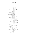
Fig. 2 is a side view of the lens holding jig; -
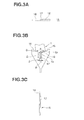
Fig. 3A is a plan view of a lower holding portion; -
Fig. 3B is a front view of the lower holding portion; -
Fig. 3C is a sectional view of the lower holding portion; -
Fig. 4 is a front view showing another example of the lower holding portion; -
Fig. 5 is a front view showing still another example of the lower holding portion; -
Fig. 6 is a front view showing still another example of the lower holding portion; -
Fig. 7A is a plan view showing still another example of the lower holding portion; -
Fig. 7B is a front view of the lower holding portion; -
Fig. 8 is a front view showing still another example of the lower holding portion; -
Fig. 9 is a front view showing still another example of the lower holding portion; -
Fig. 10 is a front view showing still another example of the lower holding portion; -
Fig. 11A is a plan view showing still another example of the lower holding portions; -
Fig. 11B is a front view of the lower holding portion; -
Fig. 12 is a front view showing still another example of the lower holding portion; -
Fig. 13 is a front view showing still another example of the lower holding portion; -
Fig. 14 is a front view showing still another example of the lower holding portion; -
Fig. 15A is a front view showing still another example of the lower holding portion; and -
Fig. 15B is a plan view of the lower holding portion. - Referring to
Figs. 1 and2 , alens base material 1 is formed from a circular lens (unprocessed lens) made of, for example, a polythiourethane resin and having a refractive index of 1.60, a center thickness of 1.0 mm, a lens diopter of 2.00, and a diameter of 65 to 80 mm. Thelens base material 1 is immersed in anapplication liquid 2 while being almost vertically held by alens holding jig 3. - As the
application liquid 2, for example, a hard coat liquid (Ne = 1.6 available from HOYA) for base material is used and stored in a hard coat tank in an environment of a temperature of 23°C (20°C to 25°C), a humidity of 35% (20% to 50%), and a wind velocity of 0.5 m/min or less. - The
lens holding jig 3 includes a holding jig main body 5, and afirst arm 6A, asecond arm 6B, and athird arm 6C which are attached to the holding jig main body 5. The holding jig main body 5 is formed from a metal plate. An inverted J-shapedhook portion 7 is integrally formed on the upper surface of one end portion so as to project upward. - The
first arm 6A, thesecond arm 6B, and thethird arm 6C are disposed to exist in the same vertical plane. Thefirst arm 6A and thethird arm 6C are disposed with their upper ends fixed on the left end side of the holding jig main body 5 inFig. 1 . On the other hand, the remainingsecond arm 6B has its upper end attached to the right end side of the holding jig main body 5. Thefirst arm 6A and thesecond arm 6B are disposed on both sides of thelens base material 1 so as to almost oppose each other. A first side holding portion 8 and a secondside holding portion 9 are integrally formed on thefirst arm 6A and thesecond arm 6B, respectively, so hold the two, left and right edges of acut end surface 1a of thelens base material 1. That is, thefirst arm 6A and thesecond arm 6B hold two points P1 and P2 on a horizontal line M passing through a geometric center O of thecut end surface 1a of thelens base material 1 or portions near the points P1 and P2. In this embodiment, the first side holding portion 8 holds a neighboring portion R1 slightly shifted upward from the point P1 of thecut end surface 1a, whereas the secondside holding portion 9 holds a neighboring portion R2 slightly shifted upward from the point P2 of thecut end surface 1a. - The
first arm 6A has its upper end fixed to the left end portion of the holding jig main body 5 by welding, soldering, or the like. The first side holding portion 8 of thefirst arm 6A is obliquely bent downward to point in the direction of the geometric center O of thelens base material 1. The distal end of the first side holding portion 8 is formed into a sharp pin shape to reduce the contact area with respect to thelens base material 1 and thus holds thecut end surface 1a at a point. - On the other hand, the
second arm 6B is pivotally supported at its upper end portion within the same vertical plane including thefirst arm 6A, thesecond arm 6B, and thethird arm 6C by ahorizontal support shaft 10 attached to the right end portion of the holding jig main body 5, Atwisted coil spring 11 serving as a biasing means applies, to thesecond arm 6B, a biasing force in the closing direction (clockwise inFig. 1 ), that is, in the direction of thefirst arm 6A. Thetwisted coil spring 11 is fitted on thesupport shaft 10 while having one end locked by the holding jig main body 5 and the other end formed on thesecond arm 6B. Anoperation lever 12 to be used to open/close thesecond arm 6B and astopper 13 which abuts against the lower surface of the holding jig main body 5 to regulate pivotal motion of thesecond arm 6B in the closing direction integrally project from the upper end side of thesecond arm 6B. The secondside holding portion 9 of thesecond arm 6B is obliquely bent downward to point in the direction of the geometric center O of thelens base material 1. The distal end of the secondside holding portion 9 is formed into a sharp pin shape to reduce the contact area with respect to thelens base material 1 and thus holds thecut end surface 1a at a point. - The
third arm 6C is arranged at a distance outside thefirst arm 6A. Thethird arm 6C includes avertical arm portion 6C-1 having its upper end fixed to the left end of the holding jig main body 5 by welding or the like, and a tiltedarm portion 6C-2 running obliquely downward from the lower end of thevertical arm portion 6C-1 and having its lower end located almost immediately under thelens base material 1. Alower holding portion 15 that holds the lower edge (lower edges S1 and S2) of thecut end surface 1a of thelens base material 1 at two points is attached to the lower end of the tiltedarm portion 6C-2. - Referring to
Figs. 3A to 3C , thelower holding portion 15 is formed from a thin metal piece (plate) having an almost arrowhead shape (inverted triangle shape) in bilateral symmetry when viewed from the front, and fixed almost vertically to the lower end of thethird arm 6C while making the obverse and reverse surfaces perpendicular tooptical surfaces 1b and 1c of thelens base material 1. The upper surface of thelower holding portion 15 is bent into a V shape so as to form support surfaces 16 that support the lower edges S1 and S2 of thecut end surface 1a of thelens base material 1 at two points. An opening angle α of the support surfaces 16 is about 90° to 120°. As shown inFig. 3C , the support surfaces 16 are formed into sharp edge shapes to support the lower edges S1 and S2 by the edges. - When the support surfaces 16 of the
lower holding portion 15 hold thecut end surface 1a of thelens base material 1, an almost triangularclosed space 19 is formed between thecut end surface 1a and the support surfaces 16. Theclosed space 19 forms a portion where theapplication liquid 2 collects after running down on thecut end surface 1a from theoptical surfaces 1b and 1c of thelens base material 1 to the support surfaces 16 of thelower holding portion 15. If theapplication liquid 2 collects in the closedspace 19, the film thickness of the application liquid applied to thecut end surface 1a of thelens base material 1 becomes uneven, resulting in an application failure. - In the present invention, the
lower holding portion 15 has an applicationliquid release portion 17 to release theapplication liquid 2 which may otherwise collect in the closedspace 19. The applicationliquid release portion 17 is formed from a vertically long hole formed at the center of thelower holding portion 15 and are open to the obverse and reverse surfaces. The hole has its upper end open to the support surfaces 16 so as to communicate with the closedspace 19. The applicationliquid release portion 17 has a cutting depth D of about 5 to 10 mm and a cutting width W of about 1 to 2 mm. - The shape and material of the
lower holding portion 15 and the shape of the applicationliquid release portion 17 are not always specific, and can be changed variously in accordance with the cut end thickness of thelens base material 1, the viscosity of theapplication liquid 2, and the like. For example, various kinds oflower holding portions 15 as shown inFigs. 4 to 15B are usable. -
Fig. 4 illustrates an example in which an applicationliquid release portion 17A is formed as a long hole having a vertical trapezoidal shape. The other components are almost the same as those of thelower holding portion 15 shown inFigs. 3A to 3C . -
Fig. 5 illustrates an example in which an applicationliquid release portion 17B is formed as a long hole having a vertical elliptical shape, and eachsupport surface 16 is formed into a convex curved surface that projects upward. The other components are almost the same as those of thelower holding portion 15 shown inFigs. 3A to 3C . -
Fig. 6 illustrates an example in which an applicationliquid release portion 17C is formed as a long hole having a vertical inverted trapezoidal shape. This shape is suitably applicable to theminus lens 1 having a thick cut end. The other components are almost the same as those of thelower holding portion 15 shown inFigs. 3A to 3C . -
Figs. 7A and 7B illustrate an example in which an applicationliquid release portion 17D is formed as a vertically long groove formed at the center of one surface, for example, asurface 15a of thelower holding portion 15. The other components are almost the same as those of thelower holding portion 15 shown inFigs. 3A to 3C . -
Fig. 8 illustrates an example in which an applicationliquid release portion 17E is formed from a verticallylong groove 18a formed at the center of a surface of thelower holding portion 15 and a hole 18b linked to the lower end of thelong groove 18a and being open to obverse andreverse surfaces lower holding portion 15. The other components are almost the same as those of thelower holding portion 15 shown inFigs. 3A to 3C . -
Fig. 9 illustrates an example in which an applicationliquid release portion 17F is formed as a long groove running from the upper end to the lower end at the center of a surface of thelower holding portion 15. The other components are almost the same as those of thelower holding portion 15 shown inFigs. 3A to 3C . -
Fig. 10 illustrates an example in which an applicationliquid release portion 17G is formed from a pair of left and right verticallylong grooves lower holding portion 15. The upper ends of thelong grooves lower holding portion 15 shown inFigs. 3A to 3C . -
Figs. 11A and 11B illustrate an example in which an applicationliquid release portion 17H is formed from verticalelliptical projections reverse surfaces lower holding portion 15. The upper ends of theprojections lower holding portion 15 shown inFigs. 3A to 3C . -
Fig. 12 illustrates thelower holding portion 15 formed from a wire rod. Thelower holding portion 15 includes a main bodywire rod portion 22 and a pair of left and right lower edge supportwire rod portions wire rod portion 22. The main bodywire rod portion 22 is formed into a U shape including twovertical pieces connection piece 22c that connects the lower ends of thevertical pieces vertical pieces connection piece 22c forms an applicationliquid release portion 17J. The pair of left and right lower edge supportwire rod portions vertical pieces cut end surface 1a of thelens base material 1. -
Fig. 13 illustrates an example in which the upper surface of thelower holding portion 15 includes the support surfaces 16 that support the lower edges S1 and S2 of thelens base material 1 at two points, andhorizontal surfaces 27 each provided on one side of acorresponding support surface 16. The other components are almost the same as those of thelower holding portion 15 shown inFigs. 3A to 3C . -
Fig. 14 illustrates an example in which an application liquid release portion 17K of thelower holding portion 15 is formed from anarrow hole 25a formed at the center of the support surfaces 16, and a horizontallong hole 25b (or long groove) communicating with the lower end of thehole 25a. The other components are almost the same as those of thelower holding portion 15 shown inFigs. 3A to 3C . -
Figs. 15A and 15B illustrate an example in which thelower holding portion 15 is formed from a chevron-shaped thin metal piece (plate) in bilateral symmetry when viewed from the front. Hence, thelower holding portion 15 has vertical side surfaces on the left and right sides, a V-shapedconcave portion 30 on theupper surfaces 16, a V-shapedconvex portion 31 projecting to the lower surface, and applicationliquid release portions 17L formed on the obverse and reverse surfaces. The applicationliquid release portion 17L includes a plurality oflong grooves 28a to 28g formed at a predetermined interval in the widthwise direction of thelower holding portion 15 and running along the full length of thelower holding portion 15 in the height direction. Thelong grooves 28a to 28g are preferably formed as V-shaped grooves having a groove width of about 1 mm and an interval of 1 to 2 mm. - A method of manufacturing a lens base material using the above-described
lens holding jig 3 will be explained next.
First, alens base material 1 to which theapplication liquid 2 is to be applied and thelens holding jig 3 shown inFig. 1 are prepared. Then, theoperation lever 12 of thesecond arm 6B of thelens holding jig 3 is made to pivot counterclockwise against the twistedcoil spring 11 inFig. 1 to open thesecond arm 6B and make the interval between the first side holding portion 8 and the secondside holding portion 9 larger than the outer diameter of thelens base material 1. In this state, thelens base material 1 is inserted between the holdingportions first arm 6A, thesecond arm 6B, and thethird arm 6C, and the lower end is placed on the support surfaces 16 of thelower holding portion 15 of thethird arm 6C. In this state, theoperation lever 12 is made to gradually pivot in the direction opposite to that described above to close thesecond arm 6B so that the first side holding portion 8 of thefirst arm 6A and the secondside holding portion 9 of thesecond arm 6B hold the left and right edges of thelens base material 1 by the biasing force of the twistedcoil spring 11. Thelens base material 1 is thus held by the first side holding portion 8 of thefirst arm 6A, the secondside holding portion 9 of thesecond arm 6B, and thelower holding portion 15 of thethird arm 6C and immersed in theapplication liquid 2 in this state together with thelens holding jig 3. - When immersing the
lens base material 1 in theapplication liquid 2, thelens base material 1 is immersed in theapplication liquid 2 to such a depth that forms no closed space between thelens holding jig 3 and thelens base material 1 in theapplication liquid 2. That is, when thelens holding jig 3 is deeply immersed in theapplication liquid 2 to submerge the holding jig main body 5 in it, thecut end surface 1a of thelens base material 1, thefirst arm 6A, thesecond arm 6B, thethird arm 6C, and the holding jig main body 5 form a closed space in theapplication liquid 2. For this reason, when thelens holding jig 3 is pulled up to withdraw thelens base material 1 from theapplication liquid 2, a film of theapplication liquid 2 is formed in the closed space. If this film bursts, some of the droplets stick to thecut end surface 1a or theoptical surfaces 1b and 1c of thelens base material 1 to form an uneven film thickness, resulting in a detective. To prevent this, the immersion depth of thelens base material 1 in theapplication liquid 2 is controlled to such a depth that forms no closed space between thelens base material 1, thefirst arm 6A, thesecond arm 6B, thethird arm 6C, and the holding jig main body 5 in theapplication liquid 2. That is, the application is performed while immersing thelens base material 1 completely and only the lower half portions of thefirst arm 6A, thesecond arm 6B, and thethird arm 6C in theapplication liquid 2 without immersing the holding jig main body 5 in it. In this immersion, no closed space is formed by thelens base material 1, thefirst arm 6A, thesecond arm 6B, thethird arm 6C, and the holding jig main body 5 in theapplication liquid 2. Since no film is formed when thelens holding jig 3 is pulled up from theapplication liquid 2, any defective caused by burst of a film can be prevented. - After confirming that the
lens base material 1 is completely immersed in theapplication liquid 2, thelens holding jig 3 is raised from theapplication liquid 2 at a withdraw speed of about 200 to 350 mm/min to withdraw thelens base material 1 from theapplication liquid 2. Upon withdrawing thelens base material 1 from theapplication liquid 2, theapplication liquid 2 sticking to thelens base material 1 runs down on theoptical surfaces 1b and 1c due to gravitation and sticks to thelower holding portion 15. - In this case, on the conventional lens holding jig that includes no application
liquid release portion 17, theapplication liquid 2 collects in the closedspace 19 formed between thecut end surface 1a and the support surfaces 16 of thelower holding portion 15. If the application liquid solidifies in this state, the coating layer is thicker at the lower edge of thecut end surface 1a than at other portions. - In the present invention, however, since there is provided the application
liquid release portion 17 running downward from the center of the support surfaces 16, theapplication liquid 2 which may otherwise collect in the closedspace 19 between thecut end surface 1a and the support surfaces 16 can further be guided downward by the applicationliquid release portion 17. Since noapplication liquid 2 collects in the closedspace 19, theapplication liquid 2 applied to thecut end surface 1a and that running down from the closedspace 19 to the applicationliquid release portion 17 can be separated. Hence, theapplication liquid 2 is applied to thecut end surface 1a in a predetermined film thickness without being affected by the application liquid remaining in the closedspace 19. - After precure, the
lens base material 1 is heated to a predetermined temperature for a predetermined time to completely solidify theapplication liquid 2. With this process, a hard coat layer is formed on, for example, thecut end surface 1a and theoptical surfaces 1b and 1c of thelens base material 1. - After formation of the hard coat layer, the
lens base material 1 is detached from thelens holding jig 3. The lower edge of thecut end surface 1a of thelens base material 1, which was held by thelower holding portion 15 of thethird arm 6C, is visually inspected, and the film thickness of the hard coat layer is evaluated based on the criterion for evaluation. If the film thickness is equal to or more than the criterion for evaluation, the lens base material is determined as a non-defective. If the film thickness is below the criterion for evaluation, the lens base material is determined as a non-defective. The manufacture of thelens base material 1 thus ends. - Experiments were conducted in which a hard coat liquid (Ne = 1.6 available from HOYA) for base material was applied to
lens base materials 1 using thelens holding jig 3 according to the present invention shown inFigs. 3A to 3C (Examples 1 to 6) and a conventional lens holding jig including no applicationliquid release portion 17 of the present invention (Comparative Examples 1 to 6). Table 1 shows the evaluation result concerning the presence/absence of film burst and the residue on the cut end. - The experiments were carried out using four kinds of
lens holding jigs 3 manufactured by forming a vertically long hole serving as an applicationliquid release portion 17 and setting a cutting depth D to 5 mm and 10 mm, a cutting width W to 1 mm and 2 mm, and an opening angle α of holdingsurfaces 16 to 90° and 120°. The components of the conventional lens holding jig are the same as those of thelens holding jig 3 according to the present invention except that the above-described applicationliquid release portion 17 is not provided on the lower holding portion. -
[Table 11 Cutting depth D (mm) Cutting width (mm) Opening W angle of support surfaces (°) Film burst Residue on cut end Example 1 5 1 90 ○ ○ Example 2 5 2 90 ○ ○ Example 3 5 2 120 ○ ⊚ Example 4 10 1 90 ○ ○ Example 5 10 2 90 ○ ○ Example 6 10 2 120 ○ ⊚ Comparative Example 1 0 0 90 × × Comparative Example 2 0 0 90 × × Comparative Example 3 0 0 120 × × Comparative Example 4 0 0 90 × × Comparative Example 5 0 0 90 × × Comparative Example 6 0 0 120 × × -
- ⊚ : completely removed
- ○ : rarely remained
- ×: remained in thick linear form
-
- ○: no failure
- ×: traces of droplet scattering
- As is apparent from Table 1, it was confirmed that film burst and residue on the cut end occurred in Comparative Examples 1 to 6, although neither film burst nor residue on the cut end occurred in Examples 1 to 6. This is supposed to be in itself the effect of providing the application
liquid release portion 17.
Claims (12)
- A lens holding jig comprising:a first arm, a second arm, and a third arm disposed on both sides of a lens base material to be held;a first side holding portion and a second side holding portion provided at lower ends of said first arm and said second arm, respectively, to hold left and right edges of a cut end surface of the lens base material; anda lower holding portion provided on said third arm to hold a lower edge of the cut end surface of the lens base material,wherein said lower holding portion comprises support surfaces that support lower edges of the cut end surface of the lens base material at two points, and an application liquid release portion running downward from said support surfaces, andwhen applying an application liquid to the lens base material, said first side holding portion, said second side holding portion, and said lower holding portion are immersed in the application liquid together with said first arm, said second arm, and said third arm.
- A lens holding jig according to claim 1, wherein said lower holding portion is formed from a plate, and has an upper surface forming said support surfaces that support the lower edge of the cut end surface of the lens base material at the two points, and said application liquid release portion being formed in at least, one of an obverse surface and a reverse surface.
- A lens holding jig according to claim 2, wherein said application liquid release portion includes a long groove.
- A lens holding jig according to claim 2, wherein said application liquid release portion includes a long hole.
- A lens holding jig according to claim 2, wherein said application liquid release portion includes a long groove formed in one of the obverse surface and the reverse surface of said lower holding portion, and a hole linked to a lower end of the long groove and being open to the obverse surface and the reverse surface of said lower holding portion.
- A lens holding jig according to claim 2, wherein said application liquid release portion includes a vertically long projection.
- A lens holding jig according to claim 1, wherein said lower holding portion is formed from a wire rod, and comprises a main body wire rod portion that forms said application liquid release portion, and lower edge support wire rod portions that support the lower edges of the cut end surface of the lens base material at two points.
- A lens holding jig according to claim 1, wherein said first arm and said second arm are arranged to oppose each other, and at least one of said first arm and said second arm freely opens/closes with respect to the other and is biased in a closing direction by biasing means.
- A lens holding jig according to claim 1, wherein the lens base material is immersed in the application liquid to such a depth that forms no closed space with respect to said lens holding jig in the application liquid.
- A lens holding jig according to claim 1, wherein the lens base material includes a plastic lens.
- A method of manufacturing a lens base material, comprising the steps of:holding a cut end surface of a lens base material using a lens holding jig of claim 1;applying an application liquid to the lens base material by immersing the lens holding jig holding the lens base material in the application liquid; andsolidifying the application liquid applied to the lens base material after withdrawing the lens holding jig from the application liquid.
- A method of manufacturing a lens base material according to claim 11, wherein the lens base material is immersed in the application liquid to such a depth that forms no closed space with respect to the lens holding jig in the application liquid.
Applications Claiming Priority (2)
| Application Number | Priority Date | Filing Date | Title |
|---|---|---|---|
| JP2009003575 | 2009-01-09 | ||
| PCT/JP2010/050024 WO2010079777A1 (en) | 2009-01-09 | 2010-01-05 | Lens holding jig and method of manufacturing lens base material using same |
Publications (3)
| Publication Number | Publication Date |
|---|---|
| EP2386900A1 true EP2386900A1 (en) | 2011-11-16 |
| EP2386900A4 EP2386900A4 (en) | 2012-08-15 |
| EP2386900B1 EP2386900B1 (en) | 2018-08-08 |
Family
ID=42316543
Family Applications (1)
| Application Number | Title | Priority Date | Filing Date |
|---|---|---|---|
| EP10729197.3A Not-in-force EP2386900B1 (en) | 2009-01-09 | 2010-01-05 | Lens holding jig |
Country Status (7)
| Country | Link |
|---|---|
| US (1) | US20120114863A1 (en) |
| EP (1) | EP2386900B1 (en) |
| JP (1) | JP5286368B2 (en) |
| KR (1) | KR101290398B1 (en) |
| CN (1) | CN102341742B (en) |
| AU (1) | AU2010204043B2 (en) |
| WO (1) | WO2010079777A1 (en) |
Families Citing this family (5)
| Publication number | Priority date | Publication date | Assignee | Title |
|---|---|---|---|---|
| FR2967987B1 (en) * | 2010-11-25 | 2012-11-23 | Scl Internat Special Coating Lab | GLASS HOLDER WITH HAMPE DEPORTEE |
| CN102789034B (en) * | 2011-05-18 | 2016-06-29 | Hoya株式会社 | Lens maintenance support and lens manufacturing method |
| CN102789035B (en) * | 2011-05-18 | 2016-08-10 | Hoya株式会社 | Lens holding support and lens manufacturing method |
| JP7618469B2 (en) * | 2021-03-15 | 2025-01-21 | ホヤ レンズ タイランド リミテッド | Holding jig, coating method for optical element, and manufacturing method for optical lens |
| JP2024072136A (en) * | 2022-11-15 | 2024-05-27 | ホヤ レンズ タイランド リミテッド | Holding jig and method for manufacturing optical element |
Family Cites Families (10)
| Publication number | Priority date | Publication date | Assignee | Title |
|---|---|---|---|---|
| JPH0693449B2 (en) * | 1989-12-25 | 1994-11-16 | 佳英 柴野 | Drying device for hot water pull-up system |
| JPH0467101A (en) * | 1990-07-09 | 1992-03-03 | Seed:Kk | Hard coating method and device for optical lens |
| JPH07234301A (en) * | 1994-02-21 | 1995-09-05 | Asahi Optical Co Ltd | Lens holding device for dip coat |
| JP4572314B2 (en) | 2000-02-25 | 2010-11-04 | セイコーエプソン株式会社 | Optical component holder and spectacle lens manufacturing method using the same |
| US6387441B1 (en) * | 2000-09-06 | 2002-05-14 | Optima, Inc. | Optical lens coating apparatus and method |
| JP4039065B2 (en) | 2001-06-18 | 2008-01-30 | セイコーエプソン株式会社 | Lens holding jig, conveying jig, and lens processing method |
| JP3838227B2 (en) | 2002-08-06 | 2006-10-25 | セイコーエプソン株式会社 | Lens holding jig |
| JP2005041703A (en) | 2003-07-22 | 2005-02-17 | Seiko Epson Corp | Holding jig |
| JP4529698B2 (en) * | 2005-01-18 | 2010-08-25 | セイコーエプソン株式会社 | Lens holding jig |
| JP2008009327A (en) | 2006-06-30 | 2008-01-17 | Hoya Corp | Dyeing method, dyeing density measuring method, dyeing density measuring device and manufacturing method for spectacle lens |
-
2010
- 2010-01-05 EP EP10729197.3A patent/EP2386900B1/en not_active Not-in-force
- 2010-01-05 KR KR1020117015689A patent/KR101290398B1/en not_active Expired - Fee Related
- 2010-01-05 US US13/143,729 patent/US20120114863A1/en not_active Abandoned
- 2010-01-05 AU AU2010204043A patent/AU2010204043B2/en not_active Ceased
- 2010-01-05 WO PCT/JP2010/050024 patent/WO2010079777A1/en not_active Ceased
- 2010-01-05 JP JP2010545761A patent/JP5286368B2/en not_active Expired - Fee Related
- 2010-01-05 CN CN2010800099515A patent/CN102341742B/en not_active Expired - Fee Related
Also Published As
| Publication number | Publication date |
|---|---|
| JP5286368B2 (en) | 2013-09-11 |
| WO2010079777A1 (en) | 2010-07-15 |
| KR20110089885A (en) | 2011-08-09 |
| AU2010204043A1 (en) | 2011-08-25 |
| CN102341742A (en) | 2012-02-01 |
| CN102341742B (en) | 2013-05-29 |
| JPWO2010079777A1 (en) | 2012-06-21 |
| EP2386900B1 (en) | 2018-08-08 |
| US20120114863A1 (en) | 2012-05-10 |
| KR101290398B1 (en) | 2013-07-26 |
| AU2010204043B2 (en) | 2015-03-05 |
| EP2386900A4 (en) | 2012-08-15 |
Similar Documents
| Publication | Publication Date | Title |
|---|---|---|
| EP2386900B1 (en) | Lens holding jig | |
| DE202016008995U1 (en) | Fusion formable glass-based articles with a metal oxide concentration gradient | |
| DE10016628A1 (en) | Process for the production of small thin glass panes and larger thin glass panes as a semi-finished product for this manufacture | |
| US11261129B2 (en) | Methods for reducing surface defects | |
| WO2017162628A1 (en) | Method for producing optical components, using functional elements | |
| EP4359358A1 (en) | Element made of brittle material having a structured edge, intermediate product, and method for producing the element | |
| DE2241785B2 (en) | Device for fastening a metal block as a clamping base on a spectacle lens | |
| WO2016117451A1 (en) | Holder and vehicle aperture plate with holder | |
| CN105171937B (en) | Keep tool, keep tool unit and scoring device | |
| EP1607781B1 (en) | Assembly of micro-optical elements on a substrate, method for adjusting the assembly and optical system comprising the assembly | |
| DE102009004379A1 (en) | Eyeglass lens blank manufacturing method, involves manufacturing blank holder by unit-wise arrangement of material such that contact surface of blank holder has shape that is adapted to surface of lens blank | |
| EP4448258A1 (en) | Method for producing spectacles lenses, and a positioning receptacle for/having a spectacles lens semifinished product | |
| US12559420B2 (en) | Glass and method of manufacturing the same | |
| WO2013023750A1 (en) | Method for structuring a flat substrate composed of glass-type material, and optical component | |
| DE68920481T2 (en) | Blocking piece and method for a laboratory for processing aspheric progressive addition lenses. | |
| JP2012529761A (en) | Solder pot | |
| DE9409745U1 (en) | Mercury drop capillary | |
| JP6702009B2 (en) | Display member surface treatment method, display member and display member surface treatment apparatus | |
| JP6691690B2 (en) | Sheet glass manufacturing apparatus and manufacturing method thereof | |
| JP5460104B2 (en) | Plastic optometry lens and method for manufacturing the same | |
| JPH0624853U (en) | Eyeglass lens fixing device | |
| JP2006199387A (en) | Lens holding jig | |
| JP4474018B2 (en) | Glass spill equipment | |
| KR20230164323A (en) | Large-area transparent reflective panel using nanocluster and manufacturing method thereof |
Legal Events
| Date | Code | Title | Description |
|---|---|---|---|
| PUAI | Public reference made under article 153(3) epc to a published international application that has entered the european phase |
Free format text: ORIGINAL CODE: 0009012 |
|
| 17P | Request for examination filed |
Effective date: 20110809 |
|
| AK | Designated contracting states |
Kind code of ref document: A1 Designated state(s): AT BE BG CH CY CZ DE DK EE ES FI FR GB GR HR HU IE IS IT LI LT LU LV MC MK MT NL NO PL PT RO SE SI SK SM TR |
|
| DAX | Request for extension of the european patent (deleted) | ||
| A4 | Supplementary search report drawn up and despatched |
Effective date: 20120712 |
|
| RIC1 | Information provided on ipc code assigned before grant |
Ipc: G02C 13/00 20060101AFI20120706BHEP Ipc: B05C 13/02 20060101ALI20120706BHEP Ipc: G02B 1/10 20060101ALI20120706BHEP Ipc: G02C 7/02 20060101ALI20120706BHEP Ipc: B05C 3/09 20060101ALI20120706BHEP |
|
| STAA | Information on the status of an ep patent application or granted ep patent |
Free format text: STATUS: EXAMINATION IS IN PROGRESS |
|
| 17Q | First examination report despatched |
Effective date: 20170529 |
|
| GRAP | Despatch of communication of intention to grant a patent |
Free format text: ORIGINAL CODE: EPIDOSNIGR1 |
|
| STAA | Information on the status of an ep patent application or granted ep patent |
Free format text: STATUS: GRANT OF PATENT IS INTENDED |
|
| RIC1 | Information provided on ipc code assigned before grant |
Ipc: B05C 13/02 20060101ALI20180228BHEP Ipc: G02B 1/10 20060101ALI20180228BHEP Ipc: B05B 13/02 20060101ALN20180228BHEP Ipc: G02C 7/02 20060101ALI20180228BHEP Ipc: B05C 3/09 20060101ALI20180228BHEP Ipc: G02C 13/00 20060101AFI20180228BHEP |
|
| INTG | Intention to grant announced |
Effective date: 20180316 |
|
| GRAS | Grant fee paid |
Free format text: ORIGINAL CODE: EPIDOSNIGR3 |
|
| GRAA | (expected) grant |
Free format text: ORIGINAL CODE: 0009210 |
|
| STAA | Information on the status of an ep patent application or granted ep patent |
Free format text: STATUS: THE PATENT HAS BEEN GRANTED |
|
| AK | Designated contracting states |
Kind code of ref document: B1 Designated state(s): AT BE BG CH CY CZ DE DK EE ES FI FR GB GR HR HU IE IS IT LI LT LU LV MC MK MT NL NO PL PT RO SE SI SK SM TR |
|
| REG | Reference to a national code |
Ref country code: GB Ref legal event code: FG4D |
|
| REG | Reference to a national code |
Ref country code: AT Ref legal event code: REF Ref document number: 1027678 Country of ref document: AT Kind code of ref document: T Effective date: 20180815 Ref country code: CH Ref legal event code: EP |
|
| REG | Reference to a national code |
Ref country code: IE Ref legal event code: FG4D |
|
| REG | Reference to a national code |
Ref country code: DE Ref legal event code: R096 Ref document number: 602010052527 Country of ref document: DE |
|
| REG | Reference to a national code |
Ref country code: NL Ref legal event code: MP Effective date: 20180808 |
|
| REG | Reference to a national code |
Ref country code: LT Ref legal event code: MG4D |
|
| REG | Reference to a national code |
Ref country code: AT Ref legal event code: MK05 Ref document number: 1027678 Country of ref document: AT Kind code of ref document: T Effective date: 20180808 |
|
| PG25 | Lapsed in a contracting state [announced via postgrant information from national office to epo] |
Ref country code: SE Free format text: LAPSE BECAUSE OF FAILURE TO SUBMIT A TRANSLATION OF THE DESCRIPTION OR TO PAY THE FEE WITHIN THE PRESCRIBED TIME-LIMIT Effective date: 20180808 Ref country code: PL Free format text: LAPSE BECAUSE OF FAILURE TO SUBMIT A TRANSLATION OF THE DESCRIPTION OR TO PAY THE FEE WITHIN THE PRESCRIBED TIME-LIMIT Effective date: 20180808 Ref country code: LT Free format text: LAPSE BECAUSE OF FAILURE TO SUBMIT A TRANSLATION OF THE DESCRIPTION OR TO PAY THE FEE WITHIN THE PRESCRIBED TIME-LIMIT Effective date: 20180808 Ref country code: FI Free format text: LAPSE BECAUSE OF FAILURE TO SUBMIT A TRANSLATION OF THE DESCRIPTION OR TO PAY THE FEE WITHIN THE PRESCRIBED TIME-LIMIT Effective date: 20180808 Ref country code: BG Free format text: LAPSE BECAUSE OF FAILURE TO SUBMIT A TRANSLATION OF THE DESCRIPTION OR TO PAY THE FEE WITHIN THE PRESCRIBED TIME-LIMIT Effective date: 20181108 Ref country code: AT Free format text: LAPSE BECAUSE OF FAILURE TO SUBMIT A TRANSLATION OF THE DESCRIPTION OR TO PAY THE FEE WITHIN THE PRESCRIBED TIME-LIMIT Effective date: 20180808 Ref country code: IS Free format text: LAPSE BECAUSE OF FAILURE TO SUBMIT A TRANSLATION OF THE DESCRIPTION OR TO PAY THE FEE WITHIN THE PRESCRIBED TIME-LIMIT Effective date: 20181208 Ref country code: NL Free format text: LAPSE BECAUSE OF FAILURE TO SUBMIT A TRANSLATION OF THE DESCRIPTION OR TO PAY THE FEE WITHIN THE PRESCRIBED TIME-LIMIT Effective date: 20180808 Ref country code: NO Free format text: LAPSE BECAUSE OF FAILURE TO SUBMIT A TRANSLATION OF THE DESCRIPTION OR TO PAY THE FEE WITHIN THE PRESCRIBED TIME-LIMIT Effective date: 20181108 Ref country code: GR Free format text: LAPSE BECAUSE OF FAILURE TO SUBMIT A TRANSLATION OF THE DESCRIPTION OR TO PAY THE FEE WITHIN THE PRESCRIBED TIME-LIMIT Effective date: 20181109 |
|
| PG25 | Lapsed in a contracting state [announced via postgrant information from national office to epo] |
Ref country code: HR Free format text: LAPSE BECAUSE OF FAILURE TO SUBMIT A TRANSLATION OF THE DESCRIPTION OR TO PAY THE FEE WITHIN THE PRESCRIBED TIME-LIMIT Effective date: 20180808 Ref country code: LV Free format text: LAPSE BECAUSE OF FAILURE TO SUBMIT A TRANSLATION OF THE DESCRIPTION OR TO PAY THE FEE WITHIN THE PRESCRIBED TIME-LIMIT Effective date: 20180808 Ref country code: ES Free format text: LAPSE BECAUSE OF FAILURE TO SUBMIT A TRANSLATION OF THE DESCRIPTION OR TO PAY THE FEE WITHIN THE PRESCRIBED TIME-LIMIT Effective date: 20180808 |
|
| PG25 | Lapsed in a contracting state [announced via postgrant information from national office to epo] |
Ref country code: RO Free format text: LAPSE BECAUSE OF FAILURE TO SUBMIT A TRANSLATION OF THE DESCRIPTION OR TO PAY THE FEE WITHIN THE PRESCRIBED TIME-LIMIT Effective date: 20180808 Ref country code: CZ Free format text: LAPSE BECAUSE OF FAILURE TO SUBMIT A TRANSLATION OF THE DESCRIPTION OR TO PAY THE FEE WITHIN THE PRESCRIBED TIME-LIMIT Effective date: 20180808 Ref country code: IT Free format text: LAPSE BECAUSE OF FAILURE TO SUBMIT A TRANSLATION OF THE DESCRIPTION OR TO PAY THE FEE WITHIN THE PRESCRIBED TIME-LIMIT Effective date: 20180808 Ref country code: EE Free format text: LAPSE BECAUSE OF FAILURE TO SUBMIT A TRANSLATION OF THE DESCRIPTION OR TO PAY THE FEE WITHIN THE PRESCRIBED TIME-LIMIT Effective date: 20180808 |
|
| REG | Reference to a national code |
Ref country code: DE Ref legal event code: R097 Ref document number: 602010052527 Country of ref document: DE |
|
| PG25 | Lapsed in a contracting state [announced via postgrant information from national office to epo] |
Ref country code: DK Free format text: LAPSE BECAUSE OF FAILURE TO SUBMIT A TRANSLATION OF THE DESCRIPTION OR TO PAY THE FEE WITHIN THE PRESCRIBED TIME-LIMIT Effective date: 20180808 Ref country code: SM Free format text: LAPSE BECAUSE OF FAILURE TO SUBMIT A TRANSLATION OF THE DESCRIPTION OR TO PAY THE FEE WITHIN THE PRESCRIBED TIME-LIMIT Effective date: 20180808 Ref country code: SK Free format text: LAPSE BECAUSE OF FAILURE TO SUBMIT A TRANSLATION OF THE DESCRIPTION OR TO PAY THE FEE WITHIN THE PRESCRIBED TIME-LIMIT Effective date: 20180808 |
|
| PLBE | No opposition filed within time limit |
Free format text: ORIGINAL CODE: 0009261 |
|
| STAA | Information on the status of an ep patent application or granted ep patent |
Free format text: STATUS: NO OPPOSITION FILED WITHIN TIME LIMIT |
|
| 26N | No opposition filed |
Effective date: 20190509 |
|
| PG25 | Lapsed in a contracting state [announced via postgrant information from national office to epo] |
Ref country code: SI Free format text: LAPSE BECAUSE OF FAILURE TO SUBMIT A TRANSLATION OF THE DESCRIPTION OR TO PAY THE FEE WITHIN THE PRESCRIBED TIME-LIMIT Effective date: 20180808 Ref country code: MC Free format text: LAPSE BECAUSE OF FAILURE TO SUBMIT A TRANSLATION OF THE DESCRIPTION OR TO PAY THE FEE WITHIN THE PRESCRIBED TIME-LIMIT Effective date: 20180808 |
|
| REG | Reference to a national code |
Ref country code: CH Ref legal event code: PL |
|
| GBPC | Gb: european patent ceased through non-payment of renewal fee |
Effective date: 20190105 |
|
| PG25 | Lapsed in a contracting state [announced via postgrant information from national office to epo] |
Ref country code: LU Free format text: LAPSE BECAUSE OF NON-PAYMENT OF DUE FEES Effective date: 20190105 |
|
| REG | Reference to a national code |
Ref country code: BE Ref legal event code: MM Effective date: 20190131 |
|
| REG | Reference to a national code |
Ref country code: IE Ref legal event code: MM4A |
|
| PGFP | Annual fee paid to national office [announced via postgrant information from national office to epo] |
Ref country code: FR Payment date: 20190920 Year of fee payment: 11 |
|
| PG25 | Lapsed in a contracting state [announced via postgrant information from national office to epo] |
Ref country code: BE Free format text: LAPSE BECAUSE OF NON-PAYMENT OF DUE FEES Effective date: 20190131 |
|
| PG25 | Lapsed in a contracting state [announced via postgrant information from national office to epo] |
Ref country code: CH Free format text: LAPSE BECAUSE OF NON-PAYMENT OF DUE FEES Effective date: 20190131 Ref country code: LI Free format text: LAPSE BECAUSE OF NON-PAYMENT OF DUE FEES Effective date: 20190131 Ref country code: GB Free format text: LAPSE BECAUSE OF NON-PAYMENT OF DUE FEES Effective date: 20190105 |
|
| PG25 | Lapsed in a contracting state [announced via postgrant information from national office to epo] |
Ref country code: IE Free format text: LAPSE BECAUSE OF NON-PAYMENT OF DUE FEES Effective date: 20190105 |
|
| PG25 | Lapsed in a contracting state [announced via postgrant information from national office to epo] |
Ref country code: TR Free format text: LAPSE BECAUSE OF FAILURE TO SUBMIT A TRANSLATION OF THE DESCRIPTION OR TO PAY THE FEE WITHIN THE PRESCRIBED TIME-LIMIT Effective date: 20180808 |
|
| PGFP | Annual fee paid to national office [announced via postgrant information from national office to epo] |
Ref country code: DE Payment date: 20190925 Year of fee payment: 11 |
|
| PG25 | Lapsed in a contracting state [announced via postgrant information from national office to epo] |
Ref country code: PT Free format text: LAPSE BECAUSE OF FAILURE TO SUBMIT A TRANSLATION OF THE DESCRIPTION OR TO PAY THE FEE WITHIN THE PRESCRIBED TIME-LIMIT Effective date: 20181208 Ref country code: MT Free format text: LAPSE BECAUSE OF NON-PAYMENT OF DUE FEES Effective date: 20190105 |
|
| PG25 | Lapsed in a contracting state [announced via postgrant information from national office to epo] |
Ref country code: CY Free format text: LAPSE BECAUSE OF FAILURE TO SUBMIT A TRANSLATION OF THE DESCRIPTION OR TO PAY THE FEE WITHIN THE PRESCRIBED TIME-LIMIT Effective date: 20180808 |
|
| PG25 | Lapsed in a contracting state [announced via postgrant information from national office to epo] |
Ref country code: HU Free format text: LAPSE BECAUSE OF FAILURE TO SUBMIT A TRANSLATION OF THE DESCRIPTION OR TO PAY THE FEE WITHIN THE PRESCRIBED TIME-LIMIT; INVALID AB INITIO Effective date: 20100105 |
|
| REG | Reference to a national code |
Ref country code: DE Ref legal event code: R119 Ref document number: 602010052527 Country of ref document: DE |
|
| PG25 | Lapsed in a contracting state [announced via postgrant information from national office to epo] |
Ref country code: FR Free format text: LAPSE BECAUSE OF NON-PAYMENT OF DUE FEES Effective date: 20210131 |
|
| PG25 | Lapsed in a contracting state [announced via postgrant information from national office to epo] |
Ref country code: DE Free format text: LAPSE BECAUSE OF NON-PAYMENT OF DUE FEES Effective date: 20210803 |
|
| PG25 | Lapsed in a contracting state [announced via postgrant information from national office to epo] |
Ref country code: MK Free format text: LAPSE BECAUSE OF FAILURE TO SUBMIT A TRANSLATION OF THE DESCRIPTION OR TO PAY THE FEE WITHIN THE PRESCRIBED TIME-LIMIT Effective date: 20180808 |