EP2386730B1 - Cold-Formed Flat Top Plunger for Use in a Hydraulic Lash Adjuster and Method of Making Same - Google Patents
Cold-Formed Flat Top Plunger for Use in a Hydraulic Lash Adjuster and Method of Making Same Download PDFInfo
- Publication number
- EP2386730B1 EP2386730B1 EP11165519.7A EP11165519A EP2386730B1 EP 2386730 B1 EP2386730 B1 EP 2386730B1 EP 11165519 A EP11165519 A EP 11165519A EP 2386730 B1 EP2386730 B1 EP 2386730B1
- Authority
- EP
- European Patent Office
- Prior art keywords
- cold
- plunger
- flat top
- forming
- wall
- Prior art date
- Legal status (The legal status is an assumption and is not a legal conclusion. Google has not performed a legal analysis and makes no representation as to the accuracy of the status listed.)
- Active
Links
Images


Classifications
-
- F—MECHANICAL ENGINEERING; LIGHTING; HEATING; WEAPONS; BLASTING
- F01—MACHINES OR ENGINES IN GENERAL; ENGINE PLANTS IN GENERAL; STEAM ENGINES
- F01L—CYCLICALLY OPERATING VALVES FOR MACHINES OR ENGINES
- F01L1/00—Valve-gear or valve arrangements, e.g. lift-valve gear
- F01L1/20—Adjusting or compensating clearance
- F01L1/22—Adjusting or compensating clearance automatically, e.g. mechanically
- F01L1/24—Adjusting or compensating clearance automatically, e.g. mechanically by fluid means, e.g. hydraulically
- F01L1/2405—Adjusting or compensating clearance automatically, e.g. mechanically by fluid means, e.g. hydraulically by means of a hydraulic adjusting device located between the cylinder head and rocker arm
-
- Y—GENERAL TAGGING OF NEW TECHNOLOGICAL DEVELOPMENTS; GENERAL TAGGING OF CROSS-SECTIONAL TECHNOLOGIES SPANNING OVER SEVERAL SECTIONS OF THE IPC; TECHNICAL SUBJECTS COVERED BY FORMER USPC CROSS-REFERENCE ART COLLECTIONS [XRACs] AND DIGESTS
- Y10—TECHNICAL SUBJECTS COVERED BY FORMER USPC
- Y10T—TECHNICAL SUBJECTS COVERED BY FORMER US CLASSIFICATION
- Y10T29/00—Metal working
- Y10T29/49—Method of mechanical manufacture
- Y10T29/49229—Prime mover or fluid pump making
- Y10T29/49298—Poppet or I.C. engine valve or valve seat making
- Y10T29/49304—Valve tappet making
Definitions
- the present disclosure is directed to a flat-faced plunger for use in a hydraulic lash adjuster and a method of manufacturing the flat-faced plunger.
- Hydraulic lash adjusters (also sometimes referred to as “lifters”) for internal combustion engines have been in use for many years to eliminate clearance (or “lash”) between engine valve train components under varying operating conditions, in order to maintain efficiency and to reduce noise and wear in the valve train.
- Hydraulic lash adjusters regulate the transfer of energy from the valve actuating cam to the valves through hydraulic fluid trapped in a pressure chamber in the plunger.
- the cam As the length of the valve actuating components varies as a result of temperature changes and wear, small quantities of hydraulic fluid are permitted to enter the pressure chamber, or escape therefrom, thus effecting an adjustment in the length of the lash adjuster, and consequently adjusting the effective total length of the valve train.
- the overall length is adjusted by configuring the rocker arm of the valve train to pivot on the lash adjuster.
- Lash adjusters often incorporate subassemblies of multiple components, including plungers. Minimizing the number of components in a subassembly reduces the amount of time and resources required to assemble the lash adjuster.
- JP-A-58 088412 discusses an overhead valve rocker mechanism supporting shaft devices are provided with an adjuster body in a plunger lifter by inflowing oil to hold a tappet clearance to an adequate value.
- US 4903651 discusses a rocker arm clearance removing device.
- US 2010/0071649 A1 discusses a cold-formed ball plunger for use in manufacturing a finished ball plunger used in a hydraulic lash adjuster that includes a check valve assembly having a check ball and a retainer.
- US 5706773 also discusses a hydraulic lash adjuster.
- US 2004/0074460 A1 relates to cold forming bodies for valve lifters in combustion engines.
- the present disclosure is directed to a cold-formed flat top plunger for use in a hydraulic lash adjuster.
- the external flat top plunger is of a one-piece construction incorporating features previously provided by subcomponents combined with the plunger, such as a shim and/or seal.
- the external flat top plunger is cold-formed to near net shape, requiring a reduced amount of machining to complete the finished part as compared to prior art plungers.
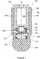
- Figure 1 illustrates a cross-sectional view of an exemplary hydraulic lash adjuster 100.
- the hydraulic lash adjuster 100 is shown by way of example only and it will be appreciated that the external flat top plunger employed therein can be used in any configuration of a hydraulic lash adjuster and is not limited to the configuration of the hydraulic lash adjuster 100 illustrated in Figure 1 .
- the structure and operation of hydraulic lash adjusters of the type shown in Figure 1 is known to those skilled in the art..
- the hydraulic lash adjuster 100 includes a lash adjuster body 102 that is configured to be disposed within a mating bore (not shown) in an engine cylinder head (not shown).
- the lash adjuster body 102 extends along longitudinal axis A and includes a first generally cylindrical exterior lash adjuster surface 104, a groove 106, a ball portion 101, and an interior surface 108 that defines a lash adjuster cavity 110.
- the groove 106 is at least partially defined by a second generally cylindrical exterior lash adjuster surface 112 that has an outer diameter that is less than the outer diameter of the first generally cylindrical exterior lash adjuster surface 104.
- the hydraulic lash adjuster 100 also includes an external flat top plunger 116 disposed in the lash adjuster cavity 110.
- the external flat top plunger 116 and lash adjuster body 102 are configured for reciprocal movement relative to one another along the longitudinal axis A.
- a plunger spring 118 is disposed within the lash adjuster cavity 110 underneath the external flat top plunger 116 and is configured to bias the external flat top plunger 116 in an upward direction relative to the lash adjuster body 102.
- the plunger spring 118 acts to maintain engagement of the ball portion 101 with the rocker arm (not shown) of the valve train (not shown).
- a retaining member 120 such as a retaining ring or washer, is provided adjacent the upper portion of the body 102.
- the external flat top plunger 116 itself defines a low pressure fluid chamber 122, while the lash adjuster body 102 and the lower portion of the external flat top plunger 116 cooperate with each other to define a high pressure fluid chamber 124 within the lash adjuster cavity 110 of the lash adjuster body 102.
- the hydraulic lash adjuster 100 includes a check valve assembly 126 positioned between the plunger spring 118 and the lower portion of the external flat top plunger 116. The check valve assembly 126 functions to either permit or block fluid communication between the low pressure fluid chamber 122 and the high pressure fluid chamber 124, in response to the pressure differential between the two fluid chambers 122, 124.
- the check valve assembly 126 includes a retainer 128 that is in engagement with a lower portion of the external flat top plunger 116, a check ball 130, and a check ball spring 132 that is disposed between the retainer 128 and the check ball 130.
- the check ball spring 132 is configured to bias the check ball 130 in an upward direction toward the external flat top plunger 116, and is therefore commonly referred to by those skilled in the art as a "normally biased closed" check valve assembly.
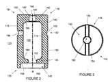
- FIG 2 is a detailed cross-sectional view of the external flat top plunger 116 employed in the exemplary hydraulic lash adjuster 100 illustrated in Figure 1 . It will be appreciated that the external flat top plunger 116 illustrated in Figures 1 and 2 is shown by way of example only and the external flat top plunger claimed herein is not limited to the configuration shown in these drawings.
- the external flat top plunger 116 is a generally cylindrical member comprising a plunger body 142 having a first end 134 and a second end 136, a side wall 178 that extends along the longitudinal axis A , and an end wall 140 at the first end 134 of the plunger body 142 defining a flat top surface 180, the end wall 140 extending transversely to the longitudinal axis A at the first end 134 of the plunger body 142.
- the flat top surface 180 at the first end 134 of the plunger body 142 is configured to engage a flat surface within the mating bore of an engine cylinder head.
- the plunger body 142 By configuring the plunger body 142 to have a flat top surface 180 that engages a flat surface disposed within the mating bore of an engine cylinder head, the force applied to the engine block by the lash adjuster 100 is distributed more evenly, minimizing wear to both the engine block and the lash adjuster 100, and in particular the flat top surface 180.
- the flat top surface In the configuration shown in Figure 2 , the flat top surface is located on either side of a shallow channel 146 and an end wall bore 182 that is defined by bore side wall 184.
- the flat top surface 180 may also be substantially flat across the entire first end 134 of the plunger body 142, uninterrupted by, for example, the shallow channel 146 and end wall bore 182.
- the side wall 178 defines a generally cylindrical exterior plunger surface 150 and a groove 152 formed in the generally cylindrical exterior plunger surface 150.
- the groove 152 cooperates with the interior surface 108 of the lash adjuster body 102 to form a fluid collector channel 154, shown in Figure 1 , and is at least partially defined by a second generally cylindrical exterior surface 156 that has an outer diameter that is less than the outer diameter of the generally cylindrical exterior plunger surface 150.
- the plunger body 142 includes a counterbore 148 configured to receive the check valve assembly 126.
- the counterbore 148 is defined by a generally cylindrical second interior side surface 158, and a flat annular surface 160 of the shoulder 144, the flat annular surface 160 being generally perpendicular to the axis A and extending from the second cylindrical interior surface 158, and a rounded annular surface 162 of the shoulder 144 that extends from the flat annular surface 160.
- the flat annular surface 160 is sized to receive the retainer 128 of the check valve assembly 126.
- the rounded annular surface 162 is sized to receive the check ball 130 of the check valve assembly 126, such that the check ball 130 engages the rounded annular surface 162 creating a fluid impermeable seal between the check ball 130 and the rounded annular surface 162 as shown in Figure 1 .
- the rounded annular surface 162 may also be referred to herein as the "ball seat 162" or the "ball seat surface 162.”
- the check ball 130 of the check valve assembly 126 sits in the check ball seat 162 defined by the shoulder 144, separating the low pressure oil chamber 122 from the high pressure chamber 124 opposite the check ball 130.
- the check ball 130 allows fluid to pass when the oil pressure in the low pressure chamber 122 reaches a sufficient level relative to the oil pressure in the high pressure chamber 124.
- the ball seat surface 162 in the illustrated embodiment of the external flat top plunger 116 is a rounded annular surface, it will be appreciated that the ball seat surface 162 can be an annular frusto-conical surface or any other desired shape so long as an appropriate seal is created between the check ball 130 and the ball seat surface 162.
- the low pressure fluid chamber 122 is surrounded by a generally cylindrical first interior surface 176.
- a plunger fluid port 186 extends radially through the side wall 178 and provides fluid communication between the outside of the plunger 123 and the fluid chamber 122.
- the fluid chamber 122 is also defined by a first transition surface 188 on the underside of the shoulder 144 that creates a transition from the ball seat surface 162 to fluid chamber 122 and a second transition surface 190 that creates a transition from the first cylindrical interior surface 176 to the end wall bore 182 that is defined by the bore side wall 184.
- the first transition surface 188 and second transition surface 190 are frusto-conical surfaces. It will be appreciated that each of these transition surfaces can additionally form, for example, an annular surface that is generally perpendicular to the axis A, a convex curved surface, or the frusto-conical surface shown, or any combination thereof.
- Figure 3 is a top view of the external flat top plunger 116 showing the first end 134 having the flat top surface 180.
- the shallow channel 146 extends across the first end 134, overlapping the end wall bore 182.
- the shallow channel 146 functions to allow a small amount of oil and any air out of the low pressure fluid chamber 122.
- Different configurations of the shallow channel 146 are permissible. For example, a configuration with two channels 146 formed in a crossing relationship may be desirable. Such an arrangement would permit narrower channels 146 and could increase the surface area of the flat top surface 180 and thereby further minimize wear to both the engine block and the lash adjuster 100, and in particular the flat top surface 180.
- Illustrated in Figure 4 is an example method 400 of producing the external flat top plunger 116 described above and illustrated in Figures 1 and 2 .
- the method 400 includes two general steps - i) cold-forming an external flat top plunger blank to near net shape, including by cold-forming the flat top surface 180, the counterbore 148, and the shoulder 144 to their respective final or net shape dimensions (step 410 ), ii) machining the cold-formed flat top plunger blank (step 420 ), and iii) applying finishing processes such as, for example, tumble finishing and heat treatment to complete the external flat top plunger 116 (step 430 ).
- final dimensions or net-shape dimensions are intended to encompass manufacture to the final set of dimensions of the workpiece or feature thereof, while still permitting further processing of the workpiece that does not alter in a significant way the final dimensions of the workpiece, such as polishing, tumble finishing, heat treatment, or other processes. Each of these finishing processes may, in a strict sense, have an effect on the dimensions of the workpiece, but as a practical matter function to provide surface finishes to a workpiece already manufactured to its final dimensions.
- near final dimensions or near net-shape dimensions are intended to encompass manufacture where many or almost all dimensions of the workpiece or feature thereof are complete, but may still require one or more machining or cold-forming processes to add or alter a dimension of the workpiece or dimension thereof.
- the term "cold-forming” is intended to encompass what is known in the art as, for example, “cold forging,” “cold heading,” and “deep drawing.”
- machining means the use of a chucking machine, drilling machine, turning machine, grinding machine, broaching machine or other such machine to remove material.
- Illustrated in Figure 5 is a cross-sectional view of one embodiment of a cold-formed flat top plunger blank 500 that is the result of the cold-forming step (step 410 ) described above.
- the cold-formed flat top plunger blank 500 is near net shape as compared to the finished flat top plunger 116.
- the external flat top plunger blank 500 which has been cold-formed to near net shape, includes a first end 134, a second end 136, and a side wall 178 extending along a longitudinal axis A.
- the first end 134 has an end wall 140 defining a flat top surface 180 that has been cold-formed to net shape.
- the end wall 140 is pierced during the cold-forming operation to form the wall bore 182 defined by bore side wall 184 and extending through the end wall 140.
- the cold-formed flat top plunger blank 500 includes a counterbore 148 and a generally cylindrical exterior surface 508, which differs from the generally cylindrical exterior plunger surface 150 in that no groove 152 or plunger fluid port 186 has yet been machined into the side wall 178.
- the counterbore 148 is defined by a second cylindrical interior surface 158 and a flat annular surface 160 that partially defines the shoulder 144.
- the flat annular surface 160 is generally perpendicular to the axis A and extends from the second cylindrical interior surface 158 (also referred to as the "retainer receiving surface 160" ) .
- a rounded annular surface 162 (also referred to as the "ball seat 162" or the “ball seat surface 162 ”) extends from the retainer receiving surface 160.
- each of these transition surfaces may additionally form, for example, an annular surface that is generally perpendicular to the axis A, a convex curved surface, the frusto-conical surface shown, or any combination thereof.
- the cold-formed flat top plunger blank 500 may be formed in a variety of cold-forming machines. Suitable examples of cold-forming machines that can be used to form the cold-formed flat top plunger blank 500 include Waterbury and National Machinery cold-forming machines.
- the cold-formed flat top plunger blank 500 may be formed from a variety of materials suitable for cold-forming, such as Society of Automotive Engineers ("SAE") grade 1018 steel or grade 1522 steel.
- SAE Society of Automotive Engineers
- cold-forming machines include a cut-off station for cutting metal wire to a desired length to provide an initial workpiece (also known as a "slug") and multiple progressive forming stations that include multiple spaced-apart die sections and a reciprocating gate having multiple punch sections, each of which cooperates with a respective die section to form a die cavity.
- a conventional transfer mechanism moves the slug in successive steps from the cut-off station to each of the forming stations in a synchronized fashion and is also capable of rotating the slug 180 degrees as it is being transferred from one station to another.
- cold-forming machines are well known in the art, no further description is necessary.
- the cold-formed flat top plunger blank 500 is formed in a five station cold-forming machine (not shown). It will, however, be appreciated that the cold-formed flat top plunger blank 500 can be produced in a different number of forming stations without departing from the scope of the invention.
- FIG. 6A-6F Illustrated in Figures 6A-6F is an exemplary cold-forming five-station slug progression sequence that can be used to form the cold-formed flat top plunger blank 500. Each figure represents the state of the slug at an end-of-stroke tool position. It will be appreciated that this slug progression sequence is merely one example of a cold-forming slug progression sequence and that other slug progression sequences are possible.
- the exemplary slug progression sequence begins with shearing wire to a desired length at the cut-off station to provide an initial slug 600, which will be described with reference to a first end 602, a second end 604, (previously referred to as the second and first end respectively) and a cylindrical surface 606 that extends there between as shown in Figure 6A .
- the ends of the slug 600 may have irregularities or unevenness inherent in the shearing process.
- the slug 600 is then transferred to the first forming station where its first end 602 faces the die section and its second end 604 faces the punch section.
- the slug 600 is squared at the first end 602 and second end 604 and a slight indentation 608 is formed in the second end 604 at the punch section of the cold-forming machine, as shown in Figure 6B .
- a chamfer 610 is simultaneously formed between the first end 602 and the cylindrical surface 606 of the slug 600.
- another indentation 612 is formed in the first end 602 of the slug 600 along with a chamfer 614 formed adjacent the indentation 612 at the first end 602. The indentation 612 helps center and guide the punch from the second forming station, which will be described in further detail below.
- the slug 600 is then rotated 180 degrees end-to-end and transferred to the second forming station where its first end 602 faces the punch section and its second end 604 faces the die section.
- a first bore 620 corresponding to the cavity 510 of the final blank, is backward extruded through the first end 602 of the slug 600 at the punch section of the cold-forming machine, as shown in Figure 6C .
- the first bore 620 is partially surrounded by the end wall 626 and side wall 628.
- a first indentation 622 and second indentation 624 are formed on either side of the end wall 626 at the second end 604 of the blank 600.
- the first indentation 622 helps center and guide the punch from the fourth forming station and reduces the thickness of the material between the two indentations 622 and 624, while the second indentation 624 narrows the thickness of the material between first indentation 622 and second indentation 624, which is removed at the fourth station.
- the portion of the end wall 636 between the first indentation 622 and second indentation 624 is later pierced to create the hole in the end wall 626 that will eventually form the end wall bore 182.
- the slug 600 is then transferred to the third forming station where its second end 604 faces the die section and its first end 602 faces the punch section.
- a hole 630 defined by side wall 634 is punched through the center of the end wall 636, removing punched material 632.
- the hole 630 will become the end wall bore 182.
- the slug 600 is then rotated 180 degrees and transferred to the fourth forming station where its second end 604 faces the punch section and its first end 602 faces the die section.
- a counterbore 640 corresponding to the counterbore 148 on the completed slug, is formed at the first end 602 of the slug 600 by the die section of the cold-forming machine.
- the counterbore 640 has a diameter greater than that of the cavity 642. Due to this size difference, the die that forms the counterbore 640 upsets the wall 644 surrounding the cavity 642, thereby preliminarily forming the shoulder 648 that will define the retainer receiving surface 160 and the ball seat surface 162 in the final cold-formed blank 500.
- the slug 600 is then rotated 180 degrees and transferred to the fifth forming station where its first end 602 faces the punch section and its second end 604 faces the die section.
- the slug 600 is formed to its final dimensions, including forming of the shallow channel 146 being formed to its final dimensions.
- the second cylindrical interior surface 158, the retainer receiving surface 160, the ball seat surface 162, and cylindrical exterior surface 508 are formed to their respective final dimensions.
- any potential sharp corners, such as at the outer edges of the first end 602 and second end 604, may be formed to create chamfers smoothing such breaks.
- the overall length of the slug 600 may be formed to the length of the blank 500, and the first end 602, in particular the flat top surface 180, and second end 604 are formed to their final shape in a coining step.
- the outer diameter of the cylindrical exterior surface 508 is formed to its final dimensions.
- the cold-formed flat top plunger blank 500 is completed and includes all of the structural features shown in Figure 5 .
- the cold-formed flat top plunger blank 500 includes all of the structural features of the finished flat top plunger 116 described above and illustrated in Figures 1 and 2 , with the exception of the structural features that must be machined. To complete the method 400 of producing the finished flat top plunger 116 described above and illustrated in Figures 1 and 2 , the cold-formed flat top plunger blank 500 is machined after cold-forming to form the remaining structural features as discussed above and shown in Figure 2 .
- the machining step (step 420 ) is performed on the completed blank 500.
- the groove 152 is machined into the generally cylindrical exterior surface 508.
- the plunger fluid port 186 is machined into the side wall 178. It will be appreciated that these machining operations can be performed one at a time, in combination with one or more other machining operations, or all together in any sequence.
- the external flat top plunger 116 described above is cold-formed to near net shape, including cold forming to final dimensions the flat top surface 180 and the counterbore 148 defined by the second cylindrical interior side surface 158, the flat annular surface 160 of the shoulder 144, and the rounded annular surface 162 of the shoulder 144 that extends from the flat annular surface 160. Cold-forming these features to final dimensions reduces the amount of machining otherwise required to complete a finished flat top plunger and thus reduces manufacturing cost of the finished ball plunger. Additionally, when compared to plunger designs that require the use of a seat insert and seal, these parts along with the associated assembly time and costs are eliminated.
Description
- The present disclosure is directed to a flat-faced plunger for use in a hydraulic lash adjuster and a method of manufacturing the flat-faced plunger.
- Hydraulic lash adjusters (also sometimes referred to as "lifters") for internal combustion engines have been in use for many years to eliminate clearance (or "lash") between engine valve train components under varying operating conditions, in order to maintain efficiency and to reduce noise and wear in the valve train. Hydraulic lash adjusters regulate the transfer of energy from the valve actuating cam to the valves through hydraulic fluid trapped in a pressure chamber in the plunger. During each operation of the cam, as the length of the valve actuating components varies as a result of temperature changes and wear, small quantities of hydraulic fluid are permitted to enter the pressure chamber, or escape therefrom, thus effecting an adjustment in the length of the lash adjuster, and consequently adjusting the effective total length of the valve train. In certain applications, the overall length is adjusted by configuring the rocker arm of the valve train to pivot on the lash adjuster.
- Lash adjusters often incorporate subassemblies of multiple components, including plungers. Minimizing the number of components in a subassembly reduces the amount of time and resources required to assemble the lash adjuster.
-
JP-A-58 088412 US 4903651 discusses a rocker arm clearance removing device. -
US 2010/0071649 A1 discusses a cold-formed ball plunger for use in manufacturing a finished ball plunger used in a hydraulic lash adjuster that includes a check valve assembly having a check ball and a retainer.US 5706773 also discusses a hydraulic lash adjuster.US 2004/0074460 A1 relates to cold forming bodies for valve lifters in combustion engines. - Aspects of the invention are set out in the accompanying claims.
- It will be appreciated that the illustrated boundaries of elements in the drawings represent only one example of the boundaries. One of ordinary skill in the art will appreciate that a single element may be designed as multiple elements or that multiple elements may be designed as a single element. An element shown as an internal feature may be implemented as an external feature and vice versa.
- Further, in the accompanying drawings and description that follow, like parts are indicated throughout the drawings and description with the same reference numerals, respectively. The figures may not be drawn to scale and the proportions of certain parts have been exaggerated for convenience of illustration.
-
Figure 1 illustrates a cross-sectional view of an exemplaryhydraulic lash adjuster 100 incorporating an externalflat top plunger 116. -
Figure 2 illustrates a detailed cross-sectional view of one embodiment of an externalflat top plunger 116 for use in the exemplaryhydraulic lash adjuster 100. -
Figure 3 illustrates a top view of one embodiment of an externalflat top plunger 116. -
Figure 4 illustrates anexample method 400 of producing the externalflat top plunger 116 described above and illustrated inFigures 1 and2 . -
Figure 5 illustrates a cross-sectional view of one embodiment of a cold-formed flat top plunger blank 500 following the cold-forming step (step 410) described inFigure 4 . -
Figures 6A-6F illustrates an exemplary cold-forming, five station slug progression sequence that can be used to form the cold-formed flat top plunger blank 500. - Certain terminology will be used in the following description for convenience in reference only and will not be limiting. The terms "upward," "downward," "upper," and "lower" will be understood to have their normal meanings and will refer to those directions as the drawing figures are normally viewed.
- The present disclosure is directed to a cold-formed flat top plunger for use in a hydraulic lash adjuster. The external flat top plunger is of a one-piece construction incorporating features previously provided by subcomponents combined with the plunger, such as a shim and/or seal. The external flat top plunger is cold-formed to near net shape, requiring a reduced amount of machining to complete the finished part as compared to prior art plungers.
-
Figure 1 illustrates a cross-sectional view of an exemplaryhydraulic lash adjuster 100. Thehydraulic lash adjuster 100 is shown by way of example only and it will be appreciated that the external flat top plunger employed therein can be used in any configuration of a hydraulic lash adjuster and is not limited to the configuration of thehydraulic lash adjuster 100 illustrated inFigure 1 . The structure and operation of hydraulic lash adjusters of the type shown inFigure 1 is known to those skilled in the art.. - As shown in
Figure 1 , thehydraulic lash adjuster 100 includes alash adjuster body 102 that is configured to be disposed within a mating bore (not shown) in an engine cylinder head (not shown). Thelash adjuster body 102 extends along longitudinal axis A and includes a first generally cylindrical exteriorlash adjuster surface 104, agroove 106, aball portion 101, and aninterior surface 108 that defines alash adjuster cavity 110. Thegroove 106 is at least partially defined by a second generally cylindrical exteriorlash adjuster surface 112 that has an outer diameter that is less than the outer diameter of the first generally cylindrical exteriorlash adjuster surface 104. - The
hydraulic lash adjuster 100 also includes an externalflat top plunger 116 disposed in thelash adjuster cavity 110. The externalflat top plunger 116 andlash adjuster body 102 are configured for reciprocal movement relative to one another along the longitudinal axis A. Aplunger spring 118 is disposed within thelash adjuster cavity 110 underneath the externalflat top plunger 116 and is configured to bias the externalflat top plunger 116 in an upward direction relative to thelash adjuster body 102. During engine operation, theplunger spring 118 acts to maintain engagement of theball portion 101 with the rocker arm (not shown) of the valve train (not shown). To limit movement of thelash adjuster 100 relative to engine cylinder head (not shown), a retaining member 120, such as a retaining ring or washer, is provided adjacent the upper portion of thebody 102. - With continued reference to
Figure 1 , the externalflat top plunger 116 itself defines a lowpressure fluid chamber 122, while thelash adjuster body 102 and the lower portion of the externalflat top plunger 116 cooperate with each other to define a highpressure fluid chamber 124 within thelash adjuster cavity 110 of thelash adjuster body 102. To control fluid flow between the lowpressure fluid chamber 122 and the highpressure fluid chamber 124, thehydraulic lash adjuster 100 includes acheck valve assembly 126 positioned between theplunger spring 118 and the lower portion of the externalflat top plunger 116. Thecheck valve assembly 126 functions to either permit or block fluid communication between the lowpressure fluid chamber 122 and the highpressure fluid chamber 124, in response to the pressure differential between the twofluid chambers - As shown in
Figure 1 , thecheck valve assembly 126 includes aretainer 128 that is in engagement with a lower portion of the externalflat top plunger 116, acheck ball 130, and acheck ball spring 132 that is disposed between theretainer 128 and thecheck ball 130. Thecheck ball spring 132 is configured to bias thecheck ball 130 in an upward direction toward the externalflat top plunger 116, and is therefore commonly referred to by those skilled in the art as a "normally biased closed" check valve assembly. -
Figure 2 is a detailed cross-sectional view of the externalflat top plunger 116 employed in the exemplaryhydraulic lash adjuster 100 illustrated inFigure 1 . It will be appreciated that the externalflat top plunger 116 illustrated inFigures 1 and2 is shown by way of example only and the external flat top plunger claimed herein is not limited to the configuration shown in these drawings. - With reference to
Figure 2 , the externalflat top plunger 116 is a generally cylindrical member comprising aplunger body 142 having afirst end 134 and asecond end 136, aside wall 178 that extends along the longitudinal axis A, and anend wall 140 at thefirst end 134 of theplunger body 142 defining aflat top surface 180, theend wall 140 extending transversely to the longitudinal axis A at thefirst end 134 of theplunger body 142. Theflat top surface 180 at thefirst end 134 of theplunger body 142 is configured to engage a flat surface within the mating bore of an engine cylinder head. By configuring theplunger body 142 to have aflat top surface 180 that engages a flat surface disposed within the mating bore of an engine cylinder head, the force applied to the engine block by thelash adjuster 100 is distributed more evenly, minimizing wear to both the engine block and thelash adjuster 100, and in particular theflat top surface 180. In the configuration shown inFigure 2 , the flat top surface is located on either side of ashallow channel 146 and anend wall bore 182 that is defined bybore side wall 184. Theflat top surface 180 may also be substantially flat across the entirefirst end 134 of theplunger body 142, uninterrupted by, for example, theshallow channel 146 and end wall bore 182. - The
side wall 178 defines a generally cylindricalexterior plunger surface 150 and agroove 152 formed in the generally cylindricalexterior plunger surface 150. Thegroove 152 cooperates with theinterior surface 108 of thelash adjuster body 102 to form afluid collector channel 154, shown inFigure 1 , and is at least partially defined by a second generally cylindricalexterior surface 156 that has an outer diameter that is less than the outer diameter of the generally cylindricalexterior plunger surface 150. - With continued reference to
Figure 2 , theplunger body 142 includes acounterbore 148 configured to receive thecheck valve assembly 126. Thecounterbore 148 is defined by a generally cylindrical secondinterior side surface 158, and a flatannular surface 160 of theshoulder 144, the flatannular surface 160 being generally perpendicular to the axis A and extending from the second cylindricalinterior surface 158, and a roundedannular surface 162 of theshoulder 144 that extends from the flatannular surface 160. The flatannular surface 160 is sized to receive theretainer 128 of thecheck valve assembly 126. The roundedannular surface 162 is sized to receive thecheck ball 130 of thecheck valve assembly 126, such that thecheck ball 130 engages the roundedannular surface 162 creating a fluid impermeable seal between thecheck ball 130 and the roundedannular surface 162 as shown inFigure 1 . Hence, the roundedannular surface 162 may also be referred to herein as the "ball seat 162" or the "ball seat surface 162." Thecheck ball 130 of thecheck valve assembly 126 sits in thecheck ball seat 162 defined by theshoulder 144, separating the lowpressure oil chamber 122 from thehigh pressure chamber 124 opposite thecheck ball 130. During normal operation, thecheck ball 130 allows fluid to pass when the oil pressure in thelow pressure chamber 122 reaches a sufficient level relative to the oil pressure in thehigh pressure chamber 124. Although theball seat surface 162 in the illustrated embodiment of the external flattop plunger 116 is a rounded annular surface, it will be appreciated that theball seat surface 162 can be an annular frusto-conical surface or any other desired shape so long as an appropriate seal is created between thecheck ball 130 and theball seat surface 162. - Generally, the low
pressure fluid chamber 122 is surrounded by a generally cylindrical firstinterior surface 176. Aplunger fluid port 186 extends radially through theside wall 178 and provides fluid communication between the outside of theplunger 123 and thefluid chamber 122. Thefluid chamber 122 is also defined by afirst transition surface 188 on the underside of theshoulder 144 that creates a transition from theball seat surface 162 tofluid chamber 122 and asecond transition surface 190 that creates a transition from the first cylindricalinterior surface 176 to the end wall bore 182 that is defined by thebore side wall 184. In the embodiment shown inFigure 2 , thefirst transition surface 188 andsecond transition surface 190 are frusto-conical surfaces. It will be appreciated that each of these transition surfaces can additionally form, for example, an annular surface that is generally perpendicular to the axis A, a convex curved surface, or the frusto-conical surface shown, or any combination thereof. -
Figure 3 is a top view of the external flattop plunger 116 showing thefirst end 134 having the flattop surface 180. Theshallow channel 146 extends across thefirst end 134, overlapping the end wall bore 182. Theshallow channel 146 functions to allow a small amount of oil and any air out of the lowpressure fluid chamber 122. Different configurations of theshallow channel 146 are permissible. For example, a configuration with twochannels 146 formed in a crossing relationship may be desirable. Such an arrangement would permitnarrower channels 146 and could increase the surface area of the flattop surface 180 and thereby further minimize wear to both the engine block and thelash adjuster 100, and in particular the flattop surface 180. - Illustrated in
Figure 4 is anexample method 400 of producing the external flattop plunger 116 described above and illustrated inFigures 1 and2 . As shown inFigure 4 , themethod 400 includes two general steps - i) cold-forming an external flat top plunger blank to near net shape, including by cold-forming the flattop surface 180, thecounterbore 148, and theshoulder 144 to their respective final or net shape dimensions (step 410), ii) machining the cold-formed flat top plunger blank (step 420), and iii) applying finishing processes such as, for example, tumble finishing and heat treatment to complete the external flat top plunger 116 (step 430). As used herein, the terms final dimensions or net-shape dimensions are intended to encompass manufacture to the final set of dimensions of the workpiece or feature thereof, while still permitting further processing of the workpiece that does not alter in a significant way the final dimensions of the workpiece, such as polishing, tumble finishing, heat treatment, or other processes. Each of these finishing processes may, in a strict sense, have an effect on the dimensions of the workpiece, but as a practical matter function to provide surface finishes to a workpiece already manufactured to its final dimensions. The terms near final dimensions or near net-shape dimensions are intended to encompass manufacture where many or almost all dimensions of the workpiece or feature thereof are complete, but may still require one or more machining or cold-forming processes to add or alter a dimension of the workpiece or dimension thereof. - As used herein, the term "cold-forming" is intended to encompass what is known in the art as, for example, "cold forging," "cold heading," and "deep drawing." As used herein, the term "machining" means the use of a chucking machine, drilling machine, turning machine, grinding machine, broaching machine or other such machine to remove material.
- Illustrated in
Figure 5 is a cross-sectional view of one embodiment of a cold-formed flat top plunger blank 500 that is the result of the cold-forming step (step 410) described above. As shown inFigure 5 , the cold-formed flat top plunger blank 500 is near net shape as compared to the finished flattop plunger 116. As shown inFigure 5 , the external flat top plunger blank 500, which has been cold-formed to near net shape, includes afirst end 134, asecond end 136, and aside wall 178 extending along a longitudinal axis A. Thefirst end 134 has anend wall 140 defining a flattop surface 180 that has been cold-formed to net shape. Theend wall 140 is pierced during the cold-forming operation to form the wall bore 182 defined bybore side wall 184 and extending through theend wall 140. - The cold-formed flat top plunger blank 500 includes a
counterbore 148 and a generally cylindricalexterior surface 508, which differs from the generally cylindricalexterior plunger surface 150 in that nogroove 152 orplunger fluid port 186 has yet been machined into theside wall 178. Thecounterbore 148 is defined by a second cylindricalinterior surface 158 and a flatannular surface 160 that partially defines theshoulder 144. The flatannular surface 160 is generally perpendicular to the axis A and extends from the second cylindrical interior surface 158 (also referred to as the "retainer receiving surface 160"). A rounded annular surface 162 (also referred to as the "ball seat 162" or the "ball seat surface 162") extends from theretainer receiving surface 160. - With continued reference to
Figure 5 , disposed within the cold-formed flat top plunger blank 500 is an axially extending bore orcavity 510 corresponding to the lowpressure fluid chamber 122 formed between theend wall 140 and theshoulder 144. Theshoulder 144 is formed between thecavity 510 and thecounterbore 148, and is defined by the flatannular surface 160, theball seat surface 162, and thefirst transition surface 188. Thecavity 510 is defined by a first cylindricalinterior surface 176, thefirst transition surface 188, andsecond transition surface 190. Thefirst transition surface 188 transitions theball seat surface 162 to the first cylindricalinterior surface 176, and asecond transition surface 190 transitions the first cylindricalinterior surface 176 to thebore side wall 184. It will be appreciated that each of these transition surfaces may additionally form, for example, an annular surface that is generally perpendicular to the axis A, a convex curved surface, the frusto-conical surface shown, or any combination thereof. - The cold-formed flat top plunger blank 500 may be formed in a variety of cold-forming machines. Suitable examples of cold-forming machines that can be used to form the cold-formed flat top plunger blank 500 include Waterbury and National Machinery cold-forming machines. The cold-formed flat top plunger blank 500 may be formed from a variety of materials suitable for cold-forming, such as Society of Automotive Engineers ("SAE") grade 1018 steel or grade 1522 steel. Generally, cold-forming machines include a cut-off station for cutting metal wire to a desired length to provide an initial workpiece (also known as a "slug") and multiple progressive forming stations that include multiple spaced-apart die sections and a reciprocating gate having multiple punch sections, each of which cooperates with a respective die section to form a die cavity. A conventional transfer mechanism moves the slug in successive steps from the cut-off station to each of the forming stations in a synchronized fashion and is also capable of rotating the
slug 180 degrees as it is being transferred from one station to another. As cold-forming machines are well known in the art, no further description is necessary. - In one embodiment, the cold-formed flat top plunger blank 500 is formed in a five station cold-forming machine (not shown). It will, however, be appreciated that the cold-formed flat top plunger blank 500 can be produced in a different number of forming stations without departing from the scope of the invention.
- Illustrated in
Figures 6A-6F is an exemplary cold-forming five-station slug progression sequence that can be used to form the cold-formed flattop plunger blank 500. Each figure represents the state of the slug at an end-of-stroke tool position. It will be appreciated that this slug progression sequence is merely one example of a cold-forming slug progression sequence and that other slug progression sequences are possible. - The exemplary slug progression sequence begins with shearing wire to a desired length at the cut-off station to provide an
initial slug 600, which will be described with reference to afirst end 602, asecond end 604, (previously referred to as the second and first end respectively) and acylindrical surface 606 that extends there between as shown inFigure 6A . At this stage, the ends of theslug 600 may have irregularities or unevenness inherent in the shearing process. Theslug 600 is then transferred to the first forming station where itsfirst end 602 faces the die section and itssecond end 604 faces the punch section. - At the first forming station, the
slug 600 is squared at thefirst end 602 andsecond end 604 and aslight indentation 608 is formed in thesecond end 604 at the punch section of the cold-forming machine, as shown inFigure 6B . At the die section of the cold-forming machine, achamfer 610 is simultaneously formed between thefirst end 602 and thecylindrical surface 606 of theslug 600. Additionally, at the die section, anotherindentation 612 is formed in thefirst end 602 of theslug 600 along with achamfer 614 formed adjacent theindentation 612 at thefirst end 602. Theindentation 612 helps center and guide the punch from the second forming station, which will be described in further detail below. Theslug 600 is then rotated 180 degrees end-to-end and transferred to the second forming station where itsfirst end 602 faces the punch section and itssecond end 604 faces the die section. - At the second forming station, a first bore 620, corresponding to the
cavity 510 of the final blank, is backward extruded through thefirst end 602 of theslug 600 at the punch section of the cold-forming machine, as shown inFigure 6C . The first bore 620 is partially surrounded by the end wall 626 andside wall 628. Simultaneously, at the die section of the cold-forming machine, afirst indentation 622 and second indentation 624 are formed on either side of the end wall 626 at thesecond end 604 of the blank 600. Thefirst indentation 622 helps center and guide the punch from the fourth forming station and reduces the thickness of the material between the twoindentations 622 and 624, while the second
indentation 624 narrows the thickness of the material betweenfirst indentation 622 and second indentation 624, which is removed at the fourth station. The portion of theend wall 636 between thefirst indentation 622 and second indentation 624 is later pierced to create the hole in the end wall 626 that will eventually form the end wall bore 182. Theslug 600 is then transferred to the third forming station where itssecond end 604 faces the die section and itsfirst end 602 faces the punch section. - As shown in
Figure 6D , at the third forming station, ahole 630 defined byside wall 634 is punched through the center of theend wall 636, removing punchedmaterial 632. Thehole 630 will become the end wall bore 182. Theslug 600 is then rotated 180 degrees and transferred to the fourth forming station where itssecond end 604 faces the punch section and itsfirst end 602 faces the die section. - As shown in
Figure 6E , acounterbore 640, corresponding to thecounterbore 148 on the completed slug, is formed at thefirst end 602 of theslug 600 by the die section of the cold-forming machine. Thecounterbore 640 has a diameter greater than that of thecavity 642. Due to this size difference, the die that forms thecounterbore 640 upsets thewall 644 surrounding thecavity 642, thereby preliminarily forming theshoulder 648 that will define theretainer receiving surface 160 and theball seat surface 162 in the final cold-formed blank 500. Theslug 600 is then rotated 180 degrees and transferred to the fifth forming station where itsfirst end 602 faces the punch section and itssecond end 604 faces the die section. - At the fifth forming station, as shown in
Figure 6F , theslug 600 is formed to its final dimensions, including forming of theshallow channel 146 being formed to its final dimensions. In addition, the second cylindricalinterior surface 158, theretainer receiving surface 160, theball seat surface 162, and cylindricalexterior surface 508 are formed to their respective final dimensions. Additionally, any potential sharp corners, such as at the outer edges of thefirst end 602 andsecond end 604, may be formed to create chamfers smoothing such breaks. The overall length of theslug 600 may be formed to the length of the blank 500, and thefirst end 602, in particular the flattop surface 180, andsecond end 604 are formed to their final shape in a coining step. Further, the outer diameter of the cylindricalexterior surface 508 is formed to its final dimensions. At the conclusion of the fifth forming station, the cold-formed flat top plunger blank 500 is completed and includes all of the structural features shown inFigure 5 . - The cold-formed flat top plunger blank 500 includes all of the structural features of the finished flat
top plunger 116 described above and illustrated inFigures 1 and2 , with the exception of the structural features that must be machined. To complete themethod 400 of producing the finished flattop plunger 116 described above and illustrated inFigures 1 and2 , the cold-formed flat top plunger blank 500 is machined after cold-forming to form the remaining structural features as discussed above and shown inFigure 2 . - The machining step (step 420) is performed on the completed blank 500. With reference to
Figures 2 and5 , thegroove 152 is machined into the generally cylindricalexterior surface 508. Additionally, theplunger fluid port 186 is machined into theside wall 178. It will be appreciated that these machining operations can be performed one at a time, in combination with one or more other machining operations, or all together in any sequence. - The external flat
top plunger 116 described above is cold-formed to near net shape, including cold forming to final dimensions the flattop surface 180 and thecounterbore 148 defined by the second cylindricalinterior side surface 158, the flatannular surface 160 of theshoulder 144, and the roundedannular surface 162 of theshoulder 144 that extends from the flatannular surface 160. Cold-forming these features to final dimensions reduces the amount of machining otherwise required to complete a finished flat top plunger and thus reduces manufacturing cost of the finished ball plunger. Additionally, when compared to plunger designs that require the use of a seat insert and seal, these parts along with the associated assembly time and costs are eliminated. - For the purposes of this disclosure and unless otherwise specified, "a" or "an" means "one or more." To the extent that the term "includes" or "including" is used in the specification or the claims, it is intended to be inclusive in a manner similar to the term "comprising" as that term is interpreted when employed as a transitional word in a claim. Furthermore, to the extent that the term "or" is employed (e.g., A or B) it is intended to mean "A or B or both." When the applicants intend to indicate "only A or B but not both" then the term "only A or B but not both" will be employed. Thus, use of the term "or" herein is the inclusive, and not the exclusive use. See, Bryan A. Garner, A Dictionary of Modern Legal Usage 624 (2d. Ed. 1995). Also, to the extent that the terms "in" or "into" are used in the specification or the claims, it is intended to additionally mean "on" or "onto." Furthermore, to the extent the term "connect" is used in the specification or claims, it is intended to mean not only "directly connected to," but also "indirectly connected to" such as connected through another component or multiple components. As used herein, "about" will be understood by persons of ordinary skill in the art and will vary to some extent depending upon the context in which it is used. If there are uses of the term which are not clear to persons of ordinary skill in the art, given the context in which it is used, "about" will mean up to plus or minus 10% of the particular term. From about X to Y is intended to mean from about X to about Y, where X and Y are the specified values.
- While the present disclosure illustrates various embodiments, and while these embodiments have been described in some detail, it is not the intention of the applicant to restrict or in any way limit the scope of the claimed invention to such detail. Additional advantages and modifications will readily appear to those skilled in the art. Therefore, the invention, in its broader aspects, is not limited to the specific details and illustrative examples shown and described. Accordingly, departures may be made from such details without departing from the scope of the claimed invention.
Claims (7)
- A cold-formed plunger blank (500) for use in a hydraulic lash adjuster (102) comprising:
a unitary cold-formed plunger body (142) that extends from a first end (134) to a second end (136) along a longitudinal axis (A), the cold-formed plunger body (142) including:an end wall (140) having a flat top surface (180) and extending transversely to the longitudinal axis (A) at the first end (134) of the plunger body (142), wherein the flat top surface (180) is formed by coining to final dimensions of a finished flat-top plunger blank (500);a side wall (178) extending along the longitudinal axis (A) between the first end (134) and the second end (136) and defining a generally cylindrical outer surface (150, 508) and a first generally cylindrical interior surface (176), the generally cylindrical outer surface (150, 508) having a common outer diameter from the first end (134) to the second end (136), the first generally cylindrical interior surface (176) defining a first inner diameter;a shoulder (144) extending from the first generally cylindrical interior surface (176) and defining a retainer receiving surface (160), a ball seat surface (162), and a first transition surface (188) joining the ball seat surface (162) with the first generally cylindrical interior surface (176);a cavity (510, 642) defined by the end wall (140), the side wall (178), and at least a portion of the shoulder (144); and,a counterbore (148) extending from the second end (136) toward the first end (134), the counterbore (148) defined at least in part by a second generally cylindrical interior surface (158) formed in the side wall (178) and the retainer receiving surface (160) of the shoulder (144), the second generally cylindrical interior surface (158) defining a second inner diameter, wherein the second inner diameter is greater than the first inner diameter. - The cold-formed plunger blank (500) of claim 1, wherein the counterbore (148) is formed to final dimensions of a finished flat-top plunger blank (500).
- A method of manufacturing a cold-formed flat top plunger (116, 500) using a cold forming machine having a cutoff station and five forming stations, the method comprising the steps of:at the cutoff station, shearing a wire to a desired length to form a slug (600) having first (136, 602) and second ends (134, 604);at the first forming station, squaring the first (136, 602) and second ends (134, 604) of the slug (600) and forming an indentation (624) in the second end (134, 604) of the slug (600);at the second forming station, extruding the slug (600) at its second end (134, 604) to form a first bore (620) that is defined by a cylindrical wall (628) and an end wall (140, 626);at the third forming station, punching through the end wall (140) of the slug (600) to form a hole (630) having a diameter smaller than a diameter of the first bore (620);at the fourth forming station, upsetting at least a portion of the cylindrical wall (628) at the first end (136, 602) to form a shoulder (144) that at least partially closes the first bore (620) to define a cavity (510, 642) and forming a flat surface (180) on the end wall (140), the cylindrical wall (628) having a similar outer diameter from the first (136, 602) end to the second end (134, 604); andat the fifth forming station, coining the shoulder (144) to form the shoulder (144) to final dimensions and forming a channel (146) in the first flat surface (180), the channel (146) and first flat surface (180) formed to final dimensions by the coining.
- The method of manufacturing a cold-formed flat top plunger (116, 500) of claim 3, wherein the extruding step comprises backward extruding the slug (600) at its second end (134, 604) to form a first bore (620) that is defined by a cylindrical wall (628) and an end wall (140).
- The method of manufacturing a cold-formed flat top plunger (116, 500) of claim 3, further comprising the step of machining a groove (152) in the cylindrical wall (628) having an outer diameter, the groove (152) defined in part by a generally cylindrical surface (156) having a diameter smaller than that of the outer diameter of the cylindrical wall (628).
- The method of manufacturing a cold-formed flat top plunger (116, 500) of claim 3, further comprising forming the overall length of the plunger (116, 500) to final dimension at the fifth forming station.
- The method of manufacturing a cold-formed flat top plunger (116, 500) of claim 3, further comprising forming the cylindrical wall (628) to final dimension at the fifth forming station.
Applications Claiming Priority (1)
| Application Number | Priority Date | Filing Date | Title |
|---|---|---|---|
| US12/777,573 US8555842B2 (en) | 2010-05-11 | 2010-05-11 | Cold-formed flat top plunger for use in a hydraulic lash adjuster and method of making same |
Publications (2)
| Publication Number | Publication Date |
|---|---|
| EP2386730A1 EP2386730A1 (en) | 2011-11-16 |
| EP2386730B1 true EP2386730B1 (en) | 2018-09-19 |
Family
ID=44276018
Family Applications (1)
| Application Number | Title | Priority Date | Filing Date |
|---|---|---|---|
| EP11165519.7A Active EP2386730B1 (en) | 2010-05-11 | 2011-05-10 | Cold-Formed Flat Top Plunger for Use in a Hydraulic Lash Adjuster and Method of Making Same |
Country Status (4)
| Country | Link |
|---|---|
| US (1) | US8555842B2 (en) |
| EP (1) | EP2386730B1 (en) |
| JP (1) | JP2011236912A (en) |
| CN (1) | CN102242808B (en) |
Families Citing this family (8)
| Publication number | Priority date | Publication date | Assignee | Title |
|---|---|---|---|---|
| US20100071649A1 (en) * | 2008-09-23 | 2010-03-25 | Eaton Corporation | Ball plunger for use in a hydraulic lash adjuster and method of making same |
| JP5943854B2 (en) * | 2013-02-15 | 2016-07-05 | 株式会社オティックス | Rush adjuster |
| US9157340B2 (en) | 2013-03-25 | 2015-10-13 | GT Technologies | Dual feed hydraulic lash adjuster for valve actuating mechanism |
| CN103212947B (en) * | 2013-04-18 | 2015-08-05 | 深圳市富泰和精密制造有限公司 | The processing method of valve lifter |
| USD785047S1 (en) | 2014-07-26 | 2017-04-25 | Eaton Corporation | Pivot plunger |
| CN104632314B (en) * | 2014-12-27 | 2017-09-19 | 海盐闻中冷挤压有限公司 | A kind of inexpensive hydraulic tappet manufacturing process |
| WO2021008734A1 (en) * | 2019-07-18 | 2021-01-21 | Eaton Intelligent Power Limited | Hla arrangement using cold formed plunger & manufacturing simplifications |
| CN115233962B (en) * | 2022-07-08 | 2023-03-21 | 广州达蒙安防科技有限公司 | Leveling component and method for building machine |
Citations (1)
| Publication number | Priority date | Publication date | Assignee | Title |
|---|---|---|---|---|
| US20040074460A1 (en) * | 2002-10-18 | 2004-04-22 | Dhruva Mandal | Valve lifter body |
Family Cites Families (37)
| Publication number | Priority date | Publication date | Assignee | Title |
|---|---|---|---|---|
| US2681644A (en) | 1950-01-05 | 1954-06-22 | Gen Motors Corp | Hydraulic lash adjuster |
| US4083334A (en) | 1973-04-26 | 1978-04-11 | Carlos Alberto Ferrari Roncon | Hydraulic valve lifter |
| US4227495A (en) | 1978-09-21 | 1980-10-14 | Eaton Corporation | Hydraulic lash adjuster with oil reservoir separator |
| US4367701A (en) | 1979-12-05 | 1983-01-11 | Eaton Corporation | Acting valve gear |
| JPS6056888B2 (en) | 1981-10-08 | 1985-12-12 | 日産自動車株式会社 | hydraulic lifter |
| JPS5888412A (en) | 1981-11-20 | 1983-05-26 | Honda Motor Co Ltd | Overhead valve rocker mechanism |
| JPS59209440A (en) | 1983-05-12 | 1984-11-28 | Honda Motor Co Ltd | Production of plunger for valve lash adjuster |
| JPS6018207U (en) * | 1983-07-18 | 1985-02-07 | 日産ディーゼル工業株式会社 | Auto adjuster for internal combustion engine |
| GB2185549B (en) * | 1985-10-15 | 1990-01-24 | Honda Motor Co Ltd | Hydraulic lash adjuster for use in a valve operating mechanism |
| US4903651A (en) | 1987-10-29 | 1990-02-27 | Honda Giken Kogyo Kabushiki Kaisha | Rocker arm clearance removing device |
| JPH01216007A (en) | 1988-02-25 | 1989-08-30 | Atsugi Motor Parts Co Ltd | Plunger for valve lash adjuster and manufacture thereof |
| GB2221279B (en) | 1988-07-22 | 1992-07-29 | Ntn Toyo Bearing Co Ltd | Belt autotensioner |
| US5515819A (en) | 1994-11-04 | 1996-05-14 | Eaton Corporation | Biasing assembly for a variable valve timing mechanism |
| US5509385A (en) | 1995-06-15 | 1996-04-23 | Precision Engine Products Corp. | Hydraulic lash adjuster metering valve |
| US5642694A (en) | 1996-05-24 | 1997-07-01 | General Motors Corporation | Integral formed oil column extender for hydraulic lash adjuster |
| US5706771A (en) | 1996-12-23 | 1998-01-13 | General Motors Corporation | Hydraulic element assembly |
| US5855191A (en) | 1997-06-23 | 1999-01-05 | Eaton Corporation | Metering valve for ball plunger or pushrod socket |
| US5901676A (en) | 1997-08-28 | 1999-05-11 | Eaton Corporation | Hydraulic lash compensator |
| US6325034B1 (en) | 2000-12-06 | 2001-12-04 | Eaton Corporation | Hydraulic lash adjuster |
| DE10100668B4 (en) | 2001-01-09 | 2005-07-14 | ZF Lemförder Metallwaren AG | Method for producing a ball joint housing |
| CA2343285C (en) | 2001-04-05 | 2004-06-15 | Proline Pipe Equipment Inc. | Actuation system for an internal backup ring assembly |
| US6871622B2 (en) * | 2002-10-18 | 2005-03-29 | Maclean-Fogg Company | Leakdown plunger |
| US7191745B2 (en) | 2002-10-18 | 2007-03-20 | Maclean-Fogg Company | Valve operating assembly |
| US7293540B2 (en) | 2002-10-18 | 2007-11-13 | Maclean-Fogg Company | Valve operating assembly and method of manufacturing |
| US7028654B2 (en) | 2002-10-18 | 2006-04-18 | The Maclean-Fogg Company | Metering socket |
| US7273026B2 (en) | 2002-10-18 | 2007-09-25 | Maclean-Fogg Company | Roller follower body |
| US7047925B2 (en) | 2004-03-03 | 2006-05-23 | Delphi Technologies, Inc. | Dual feed hydraulic lash adjuster |
| DE102004032240A1 (en) | 2004-07-03 | 2006-02-09 | Bayerische Motoren Werke Ag | Mechanical play compensation system for automotive valve drive mechanism |
| US20060016405A1 (en) | 2004-07-23 | 2006-01-26 | Harris Wayne S | Hydraulic lash adjuster having a simplified plunger |
| JP4206991B2 (en) * | 2004-10-28 | 2009-01-14 | トヨタ自動車株式会社 | Manufacturing method for valve train of internal combustion engine |
| JP4491367B2 (en) * | 2005-03-28 | 2010-06-30 | トヨタ自動車株式会社 | Diaphragm and lash adjuster |
| JP2007040291A (en) | 2005-06-28 | 2007-02-15 | Hitachi Ltd | Variable valve gear for internal combustion engine |
| JP2007077948A (en) * | 2005-09-16 | 2007-03-29 | Toyota Motor Corp | Variable valve train for internal combustion engine |
| US7350491B2 (en) | 2005-10-24 | 2008-04-01 | Eaton Corporation | Lash adjuster and valve system |
| US20080277034A1 (en) | 2007-05-09 | 2008-11-13 | The Penn State Research Foundation | Strain weakening of metallic materials |
| US7845327B2 (en) | 2007-08-19 | 2010-12-07 | Ford Global Technologies, Llc | Hydraulic lash adjuster with damping device |
| US20100071649A1 (en) * | 2008-09-23 | 2010-03-25 | Eaton Corporation | Ball plunger for use in a hydraulic lash adjuster and method of making same |
-
2010
- 2010-05-11 US US12/777,573 patent/US8555842B2/en active Active
-
2011
- 2011-05-10 EP EP11165519.7A patent/EP2386730B1/en active Active
- 2011-05-11 CN CN201110122233.5A patent/CN102242808B/en active Active
- 2011-05-11 JP JP2011106252A patent/JP2011236912A/en active Pending
Patent Citations (1)
| Publication number | Priority date | Publication date | Assignee | Title |
|---|---|---|---|---|
| US20040074460A1 (en) * | 2002-10-18 | 2004-04-22 | Dhruva Mandal | Valve lifter body |
Also Published As
| Publication number | Publication date |
|---|---|
| US20110277715A1 (en) | 2011-11-17 |
| CN102242808A (en) | 2011-11-16 |
| JP2011236912A (en) | 2011-11-24 |
| CN102242808B (en) | 2015-11-25 |
| EP2386730A1 (en) | 2011-11-16 |
| US8555842B2 (en) | 2013-10-15 |
Similar Documents
| Publication | Publication Date | Title |
|---|---|---|
| US10253659B2 (en) | Ball plunger for use in a hydraulic lash adjuster and method of making same | |
| EP2386730B1 (en) | Cold-Formed Flat Top Plunger for Use in a Hydraulic Lash Adjuster and Method of Making Same | |
| US7025025B2 (en) | Metering socket | |
| US7069891B2 (en) | Valve operating assembly and method of manufacturing | |
| US7284520B2 (en) | Valve lifter body and method of manufacture | |
| US7207302B2 (en) | Valve lifter body | |
| US7293540B2 (en) | Valve operating assembly and method of manufacturing | |
| CN113107631A (en) | Bridge part for a valve train of a heavy-duty internal combustion engine | |
| US20210362214A1 (en) | Formed outer arm for rocker arm assembly | |
| WO2009059626A1 (en) | Rocker arm | |
| US20070234989A1 (en) | Valve operating assembly and method of manufacturing |
Legal Events
| Date | Code | Title | Description |
|---|---|---|---|
| AK | Designated contracting states |
Kind code of ref document: A1 Designated state(s): AL AT BE BG CH CY CZ DE DK EE ES FI FR GB GR HR HU IE IS IT LI LT LU LV MC MK MT NL NO PL PT RO RS SE SI SK SM TR |
|
| AX | Request for extension of the european patent |
Extension state: BA ME |
|
| PUAI | Public reference made under article 153(3) epc to a published international application that has entered the european phase |
Free format text: ORIGINAL CODE: 0009012 |
|
| 17P | Request for examination filed |
Effective date: 20120516 |
|
| 17Q | First examination report despatched |
Effective date: 20140313 |
|
| STAA | Information on the status of an ep patent application or granted ep patent |
Free format text: STATUS: EXAMINATION IS IN PROGRESS |
|
| GRAP | Despatch of communication of intention to grant a patent |
Free format text: ORIGINAL CODE: EPIDOSNIGR1 |
|
| STAA | Information on the status of an ep patent application or granted ep patent |
Free format text: STATUS: GRANT OF PATENT IS INTENDED |
|
| INTG | Intention to grant announced |
Effective date: 20180403 |
|
| GRAS | Grant fee paid |
Free format text: ORIGINAL CODE: EPIDOSNIGR3 |
|
| GRAA | (expected) grant |
Free format text: ORIGINAL CODE: 0009210 |
|
| STAA | Information on the status of an ep patent application or granted ep patent |
Free format text: STATUS: THE PATENT HAS BEEN GRANTED |
|
| AK | Designated contracting states |
Kind code of ref document: B1 Designated state(s): AL AT BE BG CH CY CZ DE DK EE ES FI FR GB GR HR HU IE IS IT LI LT LU LV MC MK MT NL NO PL PT RO RS SE SI SK SM TR |
|
| REG | Reference to a national code |
Ref country code: GB Ref legal event code: FG4D |
|
| REG | Reference to a national code |
Ref country code: CH Ref legal event code: EP |
|
| REG | Reference to a national code |
Ref country code: AT Ref legal event code: REF Ref document number: 1043490 Country of ref document: AT Kind code of ref document: T Effective date: 20181015 |
|
| REG | Reference to a national code |
Ref country code: IE Ref legal event code: FG4D |
|
| REG | Reference to a national code |
Ref country code: DE Ref legal event code: R096 Ref document number: 602011052124 Country of ref document: DE |
|
| REG | Reference to a national code |
Ref country code: NL Ref legal event code: MP Effective date: 20180919 |
|
| PG25 | Lapsed in a contracting state [announced via postgrant information from national office to epo] |
Ref country code: GR Free format text: LAPSE BECAUSE OF FAILURE TO SUBMIT A TRANSLATION OF THE DESCRIPTION OR TO PAY THE FEE WITHIN THE PRESCRIBED TIME-LIMIT Effective date: 20181220 Ref country code: BG Free format text: LAPSE BECAUSE OF FAILURE TO SUBMIT A TRANSLATION OF THE DESCRIPTION OR TO PAY THE FEE WITHIN THE PRESCRIBED TIME-LIMIT Effective date: 20181219 Ref country code: RS Free format text: LAPSE BECAUSE OF FAILURE TO SUBMIT A TRANSLATION OF THE DESCRIPTION OR TO PAY THE FEE WITHIN THE PRESCRIBED TIME-LIMIT Effective date: 20180919 Ref country code: LT Free format text: LAPSE BECAUSE OF FAILURE TO SUBMIT A TRANSLATION OF THE DESCRIPTION OR TO PAY THE FEE WITHIN THE PRESCRIBED TIME-LIMIT Effective date: 20180919 Ref country code: NO Free format text: LAPSE BECAUSE OF FAILURE TO SUBMIT A TRANSLATION OF THE DESCRIPTION OR TO PAY THE FEE WITHIN THE PRESCRIBED TIME-LIMIT Effective date: 20181219 Ref country code: FI Free format text: LAPSE BECAUSE OF FAILURE TO SUBMIT A TRANSLATION OF THE DESCRIPTION OR TO PAY THE FEE WITHIN THE PRESCRIBED TIME-LIMIT Effective date: 20180919 Ref country code: SE Free format text: LAPSE BECAUSE OF FAILURE TO SUBMIT A TRANSLATION OF THE DESCRIPTION OR TO PAY THE FEE WITHIN THE PRESCRIBED TIME-LIMIT Effective date: 20180919 |
|
| REG | Reference to a national code |
Ref country code: LT Ref legal event code: MG4D |
|
| PG25 | Lapsed in a contracting state [announced via postgrant information from national office to epo] |
Ref country code: LV Free format text: LAPSE BECAUSE OF FAILURE TO SUBMIT A TRANSLATION OF THE DESCRIPTION OR TO PAY THE FEE WITHIN THE PRESCRIBED TIME-LIMIT Effective date: 20180919 Ref country code: AL Free format text: LAPSE BECAUSE OF FAILURE TO SUBMIT A TRANSLATION OF THE DESCRIPTION OR TO PAY THE FEE WITHIN THE PRESCRIBED TIME-LIMIT Effective date: 20180919 Ref country code: HR Free format text: LAPSE BECAUSE OF FAILURE TO SUBMIT A TRANSLATION OF THE DESCRIPTION OR TO PAY THE FEE WITHIN THE PRESCRIBED TIME-LIMIT Effective date: 20180919 |
|
| REG | Reference to a national code |
Ref country code: AT Ref legal event code: MK05 Ref document number: 1043490 Country of ref document: AT Kind code of ref document: T Effective date: 20180919 |
|
| PG25 | Lapsed in a contracting state [announced via postgrant information from national office to epo] |
Ref country code: PL Free format text: LAPSE BECAUSE OF FAILURE TO SUBMIT A TRANSLATION OF THE DESCRIPTION OR TO PAY THE FEE WITHIN THE PRESCRIBED TIME-LIMIT Effective date: 20180919 Ref country code: IS Free format text: LAPSE BECAUSE OF FAILURE TO SUBMIT A TRANSLATION OF THE DESCRIPTION OR TO PAY THE FEE WITHIN THE PRESCRIBED TIME-LIMIT Effective date: 20190119 Ref country code: EE Free format text: LAPSE BECAUSE OF FAILURE TO SUBMIT A TRANSLATION OF THE DESCRIPTION OR TO PAY THE FEE WITHIN THE PRESCRIBED TIME-LIMIT Effective date: 20180919 Ref country code: AT Free format text: LAPSE BECAUSE OF FAILURE TO SUBMIT A TRANSLATION OF THE DESCRIPTION OR TO PAY THE FEE WITHIN THE PRESCRIBED TIME-LIMIT Effective date: 20180919 Ref country code: RO Free format text: LAPSE BECAUSE OF FAILURE TO SUBMIT A TRANSLATION OF THE DESCRIPTION OR TO PAY THE FEE WITHIN THE PRESCRIBED TIME-LIMIT Effective date: 20180919 Ref country code: IT Free format text: LAPSE BECAUSE OF FAILURE TO SUBMIT A TRANSLATION OF THE DESCRIPTION OR TO PAY THE FEE WITHIN THE PRESCRIBED TIME-LIMIT Effective date: 20180919 Ref country code: ES Free format text: LAPSE BECAUSE OF FAILURE TO SUBMIT A TRANSLATION OF THE DESCRIPTION OR TO PAY THE FEE WITHIN THE PRESCRIBED TIME-LIMIT Effective date: 20180919 Ref country code: CZ Free format text: LAPSE BECAUSE OF FAILURE TO SUBMIT A TRANSLATION OF THE DESCRIPTION OR TO PAY THE FEE WITHIN THE PRESCRIBED TIME-LIMIT Effective date: 20180919 Ref country code: NL Free format text: LAPSE BECAUSE OF FAILURE TO SUBMIT A TRANSLATION OF THE DESCRIPTION OR TO PAY THE FEE WITHIN THE PRESCRIBED TIME-LIMIT Effective date: 20180919 |
|
| PG25 | Lapsed in a contracting state [announced via postgrant information from national office to epo] |
Ref country code: SM Free format text: LAPSE BECAUSE OF FAILURE TO SUBMIT A TRANSLATION OF THE DESCRIPTION OR TO PAY THE FEE WITHIN THE PRESCRIBED TIME-LIMIT Effective date: 20180919 Ref country code: PT Free format text: LAPSE BECAUSE OF FAILURE TO SUBMIT A TRANSLATION OF THE DESCRIPTION OR TO PAY THE FEE WITHIN THE PRESCRIBED TIME-LIMIT Effective date: 20190119 Ref country code: SK Free format text: LAPSE BECAUSE OF FAILURE TO SUBMIT A TRANSLATION OF THE DESCRIPTION OR TO PAY THE FEE WITHIN THE PRESCRIBED TIME-LIMIT Effective date: 20180919 |
|
| REG | Reference to a national code |
Ref country code: DE Ref legal event code: R097 Ref document number: 602011052124 Country of ref document: DE |
|
| PLBE | No opposition filed within time limit |
Free format text: ORIGINAL CODE: 0009261 |
|
| STAA | Information on the status of an ep patent application or granted ep patent |
Free format text: STATUS: NO OPPOSITION FILED WITHIN TIME LIMIT |
|
| PG25 | Lapsed in a contracting state [announced via postgrant information from national office to epo] |
Ref country code: DK Free format text: LAPSE BECAUSE OF FAILURE TO SUBMIT A TRANSLATION OF THE DESCRIPTION OR TO PAY THE FEE WITHIN THE PRESCRIBED TIME-LIMIT Effective date: 20180919 |
|
| 26N | No opposition filed |
Effective date: 20190620 |
|
| PG25 | Lapsed in a contracting state [announced via postgrant information from national office to epo] |
Ref country code: SI Free format text: LAPSE BECAUSE OF FAILURE TO SUBMIT A TRANSLATION OF THE DESCRIPTION OR TO PAY THE FEE WITHIN THE PRESCRIBED TIME-LIMIT Effective date: 20180919 |
|
| REG | Reference to a national code |
Ref country code: CH Ref legal event code: PL |
|
| GBPC | Gb: european patent ceased through non-payment of renewal fee |
Effective date: 20190510 |
|
| PG25 | Lapsed in a contracting state [announced via postgrant information from national office to epo] |
Ref country code: MC Free format text: LAPSE BECAUSE OF FAILURE TO SUBMIT A TRANSLATION OF THE DESCRIPTION OR TO PAY THE FEE WITHIN THE PRESCRIBED TIME-LIMIT Effective date: 20180919 Ref country code: LI Free format text: LAPSE BECAUSE OF NON-PAYMENT OF DUE FEES Effective date: 20190531 Ref country code: CH Free format text: LAPSE BECAUSE OF NON-PAYMENT OF DUE FEES Effective date: 20190531 |
|
| REG | Reference to a national code |
Ref country code: BE Ref legal event code: MM Effective date: 20190531 |
|
| PG25 | Lapsed in a contracting state [announced via postgrant information from national office to epo] |
Ref country code: LU Free format text: LAPSE BECAUSE OF NON-PAYMENT OF DUE FEES Effective date: 20190510 |
|
| PG25 | Lapsed in a contracting state [announced via postgrant information from national office to epo] |
Ref country code: TR Free format text: LAPSE BECAUSE OF FAILURE TO SUBMIT A TRANSLATION OF THE DESCRIPTION OR TO PAY THE FEE WITHIN THE PRESCRIBED TIME-LIMIT Effective date: 20180919 |
|
| PG25 | Lapsed in a contracting state [announced via postgrant information from national office to epo] |
Ref country code: IE Free format text: LAPSE BECAUSE OF NON-PAYMENT OF DUE FEES Effective date: 20190510 Ref country code: GB Free format text: LAPSE BECAUSE OF NON-PAYMENT OF DUE FEES Effective date: 20190510 |
|
| PG25 | Lapsed in a contracting state [announced via postgrant information from national office to epo] |
Ref country code: BE Free format text: LAPSE BECAUSE OF NON-PAYMENT OF DUE FEES Effective date: 20190531 |
|
| PG25 | Lapsed in a contracting state [announced via postgrant information from national office to epo] |
Ref country code: FR Free format text: LAPSE BECAUSE OF NON-PAYMENT OF DUE FEES Effective date: 20190531 |
|
| PG25 | Lapsed in a contracting state [announced via postgrant information from national office to epo] |
Ref country code: CY Free format text: LAPSE BECAUSE OF FAILURE TO SUBMIT A TRANSLATION OF THE DESCRIPTION OR TO PAY THE FEE WITHIN THE PRESCRIBED TIME-LIMIT Effective date: 20180919 |
|
| PG25 | Lapsed in a contracting state [announced via postgrant information from national office to epo] |
Ref country code: HU Free format text: LAPSE BECAUSE OF FAILURE TO SUBMIT A TRANSLATION OF THE DESCRIPTION OR TO PAY THE FEE WITHIN THE PRESCRIBED TIME-LIMIT; INVALID AB INITIO Effective date: 20110510 Ref country code: MT Free format text: LAPSE BECAUSE OF FAILURE TO SUBMIT A TRANSLATION OF THE DESCRIPTION OR TO PAY THE FEE WITHIN THE PRESCRIBED TIME-LIMIT Effective date: 20180919 |
|
| PG25 | Lapsed in a contracting state [announced via postgrant information from national office to epo] |
Ref country code: MK Free format text: LAPSE BECAUSE OF FAILURE TO SUBMIT A TRANSLATION OF THE DESCRIPTION OR TO PAY THE FEE WITHIN THE PRESCRIBED TIME-LIMIT Effective date: 20180919 |
|
| P01 | Opt-out of the competence of the unified patent court (upc) registered |
Effective date: 20230521 |
|
| PGFP | Annual fee paid to national office [announced via postgrant information from national office to epo] |
Ref country code: DE Payment date: 20230419 Year of fee payment: 13 |