EP2386718B1 - A load cell for a downhole load measuring tool - Google Patents
A load cell for a downhole load measuring tool Download PDFInfo
- Publication number
- EP2386718B1 EP2386718B1 EP11164923.2A EP11164923A EP2386718B1 EP 2386718 B1 EP2386718 B1 EP 2386718B1 EP 11164923 A EP11164923 A EP 11164923A EP 2386718 B1 EP2386718 B1 EP 2386718B1
- Authority
- EP
- European Patent Office
- Prior art keywords
- load cell
- load
- downhole
- strain
- strain gauges
- Prior art date
- Legal status (The legal status is an assumption and is not a legal conclusion. Google has not performed a legal analysis and makes no representation as to the accuracy of the status listed.)
- Not-in-force
Links
- 239000012530 fluid Substances 0.000 claims description 12
- 230000002706 hydrostatic effect Effects 0.000 claims description 11
- 239000000463 material Substances 0.000 description 4
- 238000005259 measurement Methods 0.000 description 4
- 238000004519 manufacturing process Methods 0.000 description 3
- 230000035945 sensitivity Effects 0.000 description 3
- 229910001220 stainless steel Inorganic materials 0.000 description 3
- 239000010935 stainless steel Substances 0.000 description 3
- 238000009530 blood pressure measurement Methods 0.000 description 1
- 238000009529 body temperature measurement Methods 0.000 description 1
- 230000006835 compression Effects 0.000 description 1
- 238000007906 compression Methods 0.000 description 1
- 230000000694 effects Effects 0.000 description 1
- 238000002474 experimental method Methods 0.000 description 1
- 238000013507 mapping Methods 0.000 description 1
- 238000000034 method Methods 0.000 description 1
- VIKNJXKGJWUCNN-XGXHKTLJSA-N norethisterone Chemical compound O=C1CC[C@@H]2[C@H]3CC[C@](C)([C@](CC4)(O)C#C)[C@@H]4[C@@H]3CCC2=C1 VIKNJXKGJWUCNN-XGXHKTLJSA-N 0.000 description 1
- 239000003129 oil well Substances 0.000 description 1
- 238000012360 testing method Methods 0.000 description 1
- 239000013598 vector Substances 0.000 description 1
Images


Classifications
-
- E—FIXED CONSTRUCTIONS
- E21—EARTH OR ROCK DRILLING; MINING
- E21B—EARTH OR ROCK DRILLING; OBTAINING OIL, GAS, WATER, SOLUBLE OR MELTABLE MATERIALS OR A SLURRY OF MINERALS FROM WELLS
- E21B17/00—Drilling rods or pipes; Flexible drill strings; Kellies; Drill collars; Sucker rods; Cables; Casings; Tubings
- E21B17/02—Couplings; joints
- E21B17/023—Arrangements for connecting cables or wirelines to downhole devices
-
- E—FIXED CONSTRUCTIONS
- E21—EARTH OR ROCK DRILLING; MINING
- E21B—EARTH OR ROCK DRILLING; OBTAINING OIL, GAS, WATER, SOLUBLE OR MELTABLE MATERIALS OR A SLURRY OF MINERALS FROM WELLS
- E21B47/00—Survey of boreholes or wells
- E21B47/007—Measuring stresses in a pipe string or casing
-
- G—PHYSICS
- G01—MEASURING; TESTING
- G01L—MEASURING FORCE, STRESS, TORQUE, WORK, MECHANICAL POWER, MECHANICAL EFFICIENCY, OR FLUID PRESSURE
- G01L1/00—Measuring force or stress, in general
- G01L1/20—Measuring force or stress, in general by measuring variations in ohmic resistance of solid materials or of electrically-conductive fluids; by making use of electrokinetic cells, i.e. liquid-containing cells wherein an electrical potential is produced or varied upon the application of stress
- G01L1/22—Measuring force or stress, in general by measuring variations in ohmic resistance of solid materials or of electrically-conductive fluids; by making use of electrokinetic cells, i.e. liquid-containing cells wherein an electrical potential is produced or varied upon the application of stress using resistance strain gauges
- G01L1/2206—Special supports with preselected places to mount the resistance strain gauges; Mounting of supports
- G01L1/2243—Special supports with preselected places to mount the resistance strain gauges; Mounting of supports the supports being parallelogram-shaped
Definitions
- the present invention relates to a load cell for a downhole load measuring tool, for example to measure the tension or compression applied to an oil well logging string by a wireline or tractor tool.
- Well logging engineers often require a load measuring sensor to be fitted between the top of a logging toolstring and the bottom of a wireline cable, for example on the cable head. This monitors the axial load, which is being applied directly to the toolstring. This is an important measurement to determine whether the toolstring has become stuck down the well and/or if the tension in the wireline is approaching the breaking point of the cable head.
- the cable head load sensor also helps the logging engineer to determine the forces being exerted on the toolstring by the wireline and the tractor during operations in highly deviated wells.
- US 2008/0216554 discloses a downhole load cell which acquires downhole pressure and temperature information. This downhole pressure and temperature information is used to calibrate the downhole load cell readings. However, it would be desirable not to have to take temperature and pressure measurements and then have to temperature and pressure calibrate the load cell as this increases manufacturing time and requires the load cell to have compensation files which need to be prepared and used when measurements are made.
- US 3,402,601 discloses a load cell for a downhole load measuring tool, the load cell comprising: a strain gauge arranged in a balanced array, wherein the array comprising the strain gauge is provided in fluid which, in use, is at substantially the same pressure as the surrounding downhole fluid. According to the present invention there is provided a load cell for a downhole load measuring tool, the load cell comprising:
- the load cell is preferably arranged to measure shear strain across the load cell.
- shear strain gauges rather than uni-axial gauges also allows the accuracy to be increased as the load cell does not have to resolve the wireline load on top of the well pressure force.
- a strain gauge load cell is rugged, simple, has good sensitivity and is highly linear.
- the load cell preferably has a beam upon which the balanced array of strain gauges is provided and the beam preferably has at least one flexure arranged to flex as axial load is applied to the load cell.
- a downhole tool may be provided including the load cell.
- the downhole tool may include a cable head in which the load cell is provided.
- Figure 1 illustrates a downhole unit 10 located in the borehole 20 of a well.
- the downhole unit 10 is suspended from a wireline 30 fed from a drum 40 via a pulley 50 provided at the surface.
- a load cell may be provided at any appropriate point such as in the cable head 11. As schematically illustrated in Figure 1 , the downhole unit 10 may become stuck in the borehole.
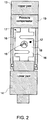
- FIG 2 shows a load cell 12 which may be used with the downhole unit 10 shown in Figure 1 .
- the load cell 12 in this example is provided between upper and lower joints 13, 14.
- Strain gauges 15 are attached to flexures 16 and the entire load cell is immersed in fluid 17 that is at the same hydrostatic pressure as the surrounding well fluid.
- the strain gauges 15 are designed specifically to measure shear strain in the flexures 16 and the flexures are arranged to bend as axial load is applied to the load cell 12.
- the load cell 12 comprises a number of groups of four strain gauges. Each group is arranged to measure shear strain in a beam 18, and the total number of strain gauges are arranged in a balanced array such as a Wheatstone bridge.
- strain gauges 15 making up the Wheatstone Bridge are shown in Figure 2 as some will be on other sides of the beam 18.
- the pressure compensator 19 which may, for example, be a piston, diaphragm etc and the material of the flexures 16 experience the resulting hydrostatic strain, the four gauges in each group of the balanced array strain by an equal amount and the balance is unaffected.
- downhole temperature variations also affect all strain gauges in the balanced array by an equal amount not affecting the balancing of the array.
- the flexures 16 experience shear strain and the bridge balance is changed accordingly. This is sensed by electronics (not shown) built into the unit.
- FIG. 3 shows a more detailed perspective view of the load cell 12.
- Two strain gauges 15 can be seen orientated perpendicular to each other.
- Two other strain gauges (not shown) are arranged similarly on the reverse side of the beam 18 also in a perpendicular arrangement to each other.
- each strain gauge 15 is a resistance element with the four individual resistance elements arranged in a Wheatstone Bridge using appropriate electrical connections 20.
- the beam 18 may be made from any suitable material.
- the beam 18 is made from stainless steel.
- the beam material is preferably selected to have a Modulus of Elasticity which is substantially matched to that of the material from which the strain gauges 15 are made.
- the beam 18 is made from stainless steel 17-4 PH.
- the stainless steel may have been heat treated to provide sufficient strength to withstand the downhole conditions.
- Figure 4 schematically illustrates the elastic strain experienced by the beam 18 when the load cell 12 experiences a load of 12000 N.
- different levels of strain are experienced across the cell, in particular greatest strain is experienced around the flexures 16.
- the resulting electrical output is detected by an appropriate controller, such as a microprocessor or electrical circuit (not shown) to provide an indication of the load to which the load cell 12 and thus the downhole unit 10 is subjected.
- the strain gauges 15 are arranged in a balanced array and subjected to the downhole pressure via the pressure compensator 19, this results in the load cell 12 straining uniformly in all directions as a result of the downhole pressure such that the overall strain measured by the balanced array of strain gauges due to the downhole pressure will effectively be zero.
- the load cell illustrated in Figure 2 was baked in an oven with the temperature cycled from room temperature up to 177°C while attached to a data logger recording the load cell balance voltage and load cell temperature simultaneously. It was found that errors of less than 0.5%, more typically of 0.2% or less are experienced by this ambient temperature variation. This deviation is sufficiently small that it does not need to be compensated for in the sensor electronics providing a simpler, more reliable and less expensive control arrangement.
- the load cell 12 is calibrated such that an associated controller provides an indication of the load to which the load cell 12 is subjected, for example by using a look-up table or appropriate algorithm for example mapping output voltages of the balanced array to corresponding loads.
- the indication of the load to which the load cell 12 and thus the tool string is subjected may be displayed to appropriate operators at the surface or stored for later analysis or both.
- An advantageous element of embodiments of the invention is using shear strain gauges in a pressure balanced environment, where the gauges experience full hydrostatic pressure from all directions.
- Using a load cell of an embodiment of the present invention produces a significant improvement in measurement resolution, as well as a much simplified calibration process.
- the output of the load cell is essentially linear, therefore calibration can be performed with three measurement points.
- any suitable pressure compensator 19 may be used to apply the external downhole hydrostatic pressure, when in use, to the fluid within the load cell in which the balanced array of strain gauges is provided, such as a piston, diaphragm, bellows etc.
Landscapes
- Engineering & Computer Science (AREA)
- Geology (AREA)
- Physics & Mathematics (AREA)
- Life Sciences & Earth Sciences (AREA)
- Mining & Mineral Resources (AREA)
- Environmental & Geological Engineering (AREA)
- Fluid Mechanics (AREA)
- General Life Sciences & Earth Sciences (AREA)
- Geochemistry & Mineralogy (AREA)
- Mechanical Engineering (AREA)
- General Physics & Mathematics (AREA)
- Geophysics (AREA)
- Force Measurement Appropriate To Specific Purposes (AREA)
- Measurement Of Force In General (AREA)
Description
- The present invention relates to a load cell for a downhole load measuring tool, for example to measure the tension or compression applied to an oil well logging string by a wireline or tractor tool.
- Well logging engineers often require a load measuring sensor to be fitted between the top of a logging toolstring and the bottom of a wireline cable, for example on the cable head. This monitors the axial load, which is being applied directly to the toolstring. This is an important measurement to determine whether the toolstring has become stuck down the well and/or if the tension in the wireline is approaching the breaking point of the cable head. The cable head load sensor also helps the logging engineer to determine the forces being exerted on the toolstring by the wireline and the tractor during operations in highly deviated wells.
- A challenge faced when designing a cable head load unit is to decouple the axial load created by downhole hydrostatic pressure alone, from the load applied by the wireline or tractor. In a deep well the hydrostatic pressure will result in tens of thousands of pounds (10,000 pounds = 44482.22 newtons) of axial compressive force to be applied to the toolstring and this is an order of magnitude greater than the maximum potential wireline force.
-
US 2008/0216554 discloses a downhole load cell which acquires downhole pressure and temperature information. This downhole pressure and temperature information is used to calibrate the downhole load cell readings. However, it would be desirable not to have to take temperature and pressure measurements and then have to temperature and pressure calibrate the load cell as this increases manufacturing time and requires the load cell to have compensation files which need to be prepared and used when measurements are made. -
US 3,402,601 discloses a load cell for a downhole load measuring tool, the load cell comprising: a strain gauge arranged in a balanced array, wherein the array comprising the strain gauge is provided in fluid which, in use, is at substantially the same pressure as the surrounding downhole fluid. According to the present invention there is provided a load cell for a downhole load measuring tool, the load cell comprising: - a plurality of strain gauges arranged in a balanced array, wherein the array of strain gauges is provided in fluid which, in use, is at substantially the same pressure as the surrounding downhole fluid; and
- a pressure compensator configured to apply hydrostatic strain to the balanced array, and when subjected to such strain, the balanced array is configured such that each shear strain gauge of the balanced array is uniformly strained.
- The load cell is preferably arranged to measure shear strain across the load cell. The use of shear strain gauges, rather than uni-axial gauges also allows the accuracy to be increased as the load cell does not have to resolve the wireline load on top of the well pressure force.
- A strain gauge load cell is rugged, simple, has good sensitivity and is highly linear.
- The load cell preferably has a beam upon which the balanced array of strain gauges is provided and the beam preferably has at least one flexure arranged to flex as axial load is applied to the load cell.
- A downhole tool may be provided including the load cell. The downhole tool may include a cable head in which the load cell is provided.
- Embodiments of the present invention will now be described, by way of example only, with reference to the accompanying drawings, in which:
-
Figure 1 shows a downhole unit located in the borehole of a well; -
Figure 2 shows a load cell of an example of the present invention; -
Figure 3 is a more detailed perspective view of the load cell shown inFigure 2 ; and -
Figure 4 schematically illustrates the elastic strain experienced by the load cell under a load. -
Figure 1 illustrates adownhole unit 10 located in theborehole 20 of a well. - The
downhole unit 10 is suspended from awireline 30 fed from adrum 40 via apulley 50 provided at the surface. A load cell may be provided at any appropriate point such as in thecable head 11. As schematically illustrated inFigure 1 , thedownhole unit 10 may become stuck in the borehole. -
Figure 2 shows aload cell 12 which may be used with thedownhole unit 10 shown inFigure 1 . Theload cell 12 in this example is provided between upper andlower joints Strain gauges 15 are attached toflexures 16 and the entire load cell is immersed influid 17 that is at the same hydrostatic pressure as the surrounding well fluid. Thestrain gauges 15 are designed specifically to measure shear strain in theflexures 16 and the flexures are arranged to bend as axial load is applied to theload cell 12. Theload cell 12 comprises a number of groups of four strain gauges. Each group is arranged to measure shear strain in abeam 18, and the total number of strain gauges are arranged in a balanced array such as a Wheatstone bridge. Not all of thestrain gauges 15 making up the Wheatstone Bridge are shown inFigure 2 as some will be on other sides of thebeam 18. As external downhole hydrostatic pressure is applied via thepressure compensator 19 which may, for example, be a piston, diaphragm etc and the material of theflexures 16 experience the resulting hydrostatic strain, the four gauges in each group of the balanced array strain by an equal amount and the balance is unaffected. Similarly, downhole temperature variations also affect all strain gauges in the balanced array by an equal amount not affecting the balancing of the array. However, as axial load is applied to the cell, theflexures 16 experience shear strain and the bridge balance is changed accordingly. This is sensed by electronics (not shown) built into the unit. -
Figure 3 shows a more detailed perspective view of theload cell 12. Twostrain gauges 15 can be seen orientated perpendicular to each other. Two other strain gauges (not shown) are arranged similarly on the reverse side of thebeam 18 also in a perpendicular arrangement to each other. In this example eachstrain gauge 15 is a resistance element with the four individual resistance elements arranged in a Wheatstone Bridge using appropriateelectrical connections 20. - The
beam 18 may be made from any suitable material. In this example thebeam 18 is made from stainless steel. The beam material is preferably selected to have a Modulus of Elasticity which is substantially matched to that of the material from which thestrain gauges 15 are made. In this example thebeam 18 is made from stainless steel 17-4 PH. The stainless steel may have been heat treated to provide sufficient strength to withstand the downhole conditions. -
Figure 4 schematically illustrates the elastic strain experienced by thebeam 18 when theload cell 12 experiences a load of 12000 N. As can be seen fromFigure 4 , different levels of strain are experienced across the cell, in particular greatest strain is experienced around theflexures 16. During use these different strains experienced in different parts of thebeam 18 are detected by the plurality ofstrain gauges 15. The resulting electrical output, in this example with thestrain gauges 15 arranged in a Wheatstone Bridge, is detected by an appropriate controller, such as a microprocessor or electrical circuit (not shown) to provide an indication of the load to which theload cell 12 and thus thedownhole unit 10 is subjected. - As explained above, as the
strain gauges 15 are arranged in a balanced array and subjected to the downhole pressure via thepressure compensator 19, this results in theload cell 12 straining uniformly in all directions as a result of the downhole pressure such that the overall strain measured by the balanced array of strain gauges due to the downhole pressure will effectively be zero. - Pressure tests were performed on the load cell illustrated in
Figure 2 using an oil containment flask filled with Capella oil into which the load cell was immersed. The Wheatstone Bridge was energized to +/- 5 volts using a laboratory power supply with the balance voltage amplified 100x with an op-amplifier circuit before being read using a digital volt meter. With this configuration and with a full load of 12000 N, the sensitivity of theload cell 12 was found to be 11.7 N/mV. Experimental results found that varying the ambient pressure from 0 to 20000 psi (1.38 x 10⁵ kN/m2) led to a maximum variation in balance voltage of the Wheatstone Bridge of a few milli volts representing an error of less than half a percent of the measured load, more typically of 0.2% or less, such that compensation for the downhole pressure variation is not necessary, providing a simpler, more reliable and less expensive control arrangement. - Experiments were also performed to determine whether there would be any affect on the sensitivity of the balanced array of strain gauges due to variations in temperature caused by the downhole fluids in which the load cell would be used.
- The load cell illustrated in
Figure 2 was baked in an oven with the temperature cycled from room temperature up to 177°C while attached to a data logger recording the load cell balance voltage and load cell temperature simultaneously. It was found that errors of less than 0.5%, more typically of 0.2% or less are experienced by this ambient temperature variation. This deviation is sufficiently small that it does not need to be compensated for in the sensor electronics providing a simpler, more reliable and less expensive control arrangement. - Use of the load cell described above in downhole pressure and temperature environments results in the
strain gauges 15 all getting slightly shorter under increased hydrostatic pressure and getting slightly longer due to elevated temperatures. However, despite the elevated pressures and temperatures to which theload cell 12 is subjected, the balance of the array ofstrain gauges 15 is maintained. However, as illustrated in ourFigure 4 , when theload cell 12 is subjected to a load (in the example ofFigure 4 a load of 12000 N is used) there is a difference in strain across thecell 12. This difference results in one of the principle vectors pointing inwards whilst the other points outwards resulting in two of the strain gauges 15 getting longer whilst the other two get shorter changing the balance of the Wheatstone Bridge. This change in the balance results in an output voltage which is indicative of the load to which the load cell is subjected. - The
load cell 12 is calibrated such that an associated controller provides an indication of the load to which theload cell 12 is subjected, for example by using a look-up table or appropriate algorithm for example mapping output voltages of the balanced array to corresponding loads. The indication of the load to which theload cell 12 and thus the tool string is subjected may be displayed to appropriate operators at the surface or stored for later analysis or both. - An advantageous element of embodiments of the invention is using shear strain gauges in a pressure balanced environment, where the gauges experience full hydrostatic pressure from all directions.
- Another advantage with using this configuration, is that under the effects of both temperature and hydrostatic pressure, the strain elements are all deformed by the same amount, theoretically producing no overall change in the balance of the array such as the Wheatstone Bridge. Change in balance is only created when non pressure or temperature related loading generates shear strain in the load cell. In practice, due to imperfections in the
gauges 15, there will be some error deviation. However, this has been found to be sufficiently small as to be considered negligible. - Using a load cell of an embodiment of the present invention produces a significant improvement in measurement resolution, as well as a much simplified calibration process. The output of the load cell is essentially linear, therefore calibration can be performed with three measurement points. There is also no requirement to temperature or pressure calibrate the tool as this is all compensated for by the balanced array, such as a Wheatstone bridge arrangement of the strain gauges. This significantly reduces the manufacturing time, and removes the need for compensation files to be supplied to the client with the tool.
- Many variations may be made to the examples described above whilst still falling within the scope of the present invention. For example, although two flexures are illustrated, one or three or more flexures could be used. Furthermore, any
suitable pressure compensator 19 may be used to apply the external downhole hydrostatic pressure, when in use, to the fluid within the load cell in which the balanced array of strain gauges is provided, such as a piston, diaphragm, bellows etc.
Claims (9)
- A load cell (12) for a downhole load measuring tool, the load cell comprising:a plurality of strain gauges (15) arranged in a balanced array, wherein the array of strain gauges is provided in fluid (17) which, in use, is at substantially the same pressure as the surrounding downhole fluid; anda pressure compensator (19) configured to apply hydrostatic strain to the balanced array, and when subjected to such strain, the balanced array is configured such that each shear strain gauge of the balanced array is uniformly strained.
- A load cell according to claim 1, wherein the load cell is arranged to measure shear strain across the load cell.
- A load cell according to claim 1 or claim 2, wherein the load cell has a beam (18) upon which the balanced array of strain gauges (15) is provided and the beam includes at least one flexure (16) arranged to flex as axial load is applied to the load cell.
- A load cell according to claim 3, wherein the beam (18) has two flexures (16) arranged on different sides of the beam.
- A load cell according to claim 3 or claim 4, wherein the Modulus of Elasticity of the beam is substantially matched to that of the strain gauges.
- A load cell according to any one of the preceding claims, wherein the balanced array is a Wheatstone Bridge.
- A load cell according to any one of the preceding claims, wherein the array of strain gauges is provided in fluid (17) which, in use, is also at substantially the same temperature as the surrounding downhole fluid.
- A downhole load measuring tool (10) including a load cell (12) according to any one of the preceding claims.
- A downhole load measuring tool according to claim 8, having a cable head (11) in which the load cell (12) is provided.
Applications Claiming Priority (1)
| Application Number | Priority Date | Filing Date | Title |
|---|---|---|---|
| GBGB1007813.7A GB201007813D0 (en) | 2010-05-11 | 2010-05-11 | A load cell for a downhole load measuring tool |
Publications (3)
| Publication Number | Publication Date |
|---|---|
| EP2386718A2 EP2386718A2 (en) | 2011-11-16 |
| EP2386718A3 EP2386718A3 (en) | 2017-04-19 |
| EP2386718B1 true EP2386718B1 (en) | 2018-08-01 |
Family
ID=42315108
Family Applications (1)
| Application Number | Title | Priority Date | Filing Date |
|---|---|---|---|
| EP11164923.2A Not-in-force EP2386718B1 (en) | 2010-05-11 | 2011-05-05 | A load cell for a downhole load measuring tool |
Country Status (4)
| Country | Link |
|---|---|
| US (1) | US8939039B2 (en) |
| EP (1) | EP2386718B1 (en) |
| CA (1) | CA2739222C (en) |
| GB (1) | GB201007813D0 (en) |
Families Citing this family (12)
| Publication number | Priority date | Publication date | Assignee | Title |
|---|---|---|---|---|
| CH707008A1 (en) * | 2012-09-27 | 2014-03-31 | Kistler Holding Ag | Strain transmitter. |
| WO2014099723A1 (en) * | 2012-12-18 | 2014-06-26 | Schlumberger Canada Limited | Pump down conveyance |
| US9376906B2 (en) * | 2012-12-20 | 2016-06-28 | Schlumberger Technology Corporation | Downhole cable sensor |
| US9416648B2 (en) * | 2013-08-29 | 2016-08-16 | Schlumberger Technology Corporation | Pressure balanced flow through load measurement |
| US10264043B2 (en) * | 2014-04-23 | 2019-04-16 | Ericsson Ab | Outage notification with client control modification in an ABR streaming network |
| WO2017039650A1 (en) | 2015-09-02 | 2017-03-09 | Halliburton Energy Services, Inc. | Determining downhole forces using pressure differentials |
| US10858897B2 (en) | 2016-01-27 | 2020-12-08 | Halliburton Energy Services, Inc. | Downhole armored optical cable tension measurement |
| US20170268328A1 (en) * | 2016-03-17 | 2017-09-21 | Schlumberger Technology Corporation | Identification of pumping system placement |
| NO343697B1 (en) * | 2017-05-23 | 2019-05-13 | Altus Intervention Tech As | Method and apparatus for performing a survey of tubing which is stuck in a borehole, e.g. for determining a free point |
| US11761749B2 (en) | 2018-12-13 | 2023-09-19 | Halliburton Energy Services, Inc. | Strain magnification |
| CN111272327B (en) * | 2020-03-17 | 2021-08-24 | 国网河南省电力公司电力科学研究院 | A fiber grating three-dimensional tension sensor |
| CN113959635A (en) * | 2021-09-02 | 2022-01-21 | 中国科学院合肥物质科学研究院 | Hydraulic type calibration device and method for flexible force-sensitive sensor array |
Family Cites Families (18)
| Publication number | Priority date | Publication date | Assignee | Title |
|---|---|---|---|---|
| US2703491A (en) * | 1949-10-21 | 1955-03-08 | Phillips Petroleum Co | Strain measuring instrument |
| US3402601A (en) * | 1965-10-28 | 1968-09-24 | Schlumberger Technology Corp | Tension measuring device |
| FR2430003A1 (en) | 1978-06-30 | 1980-01-25 | Schlumberger Prospection | DEVICE FOR MEASURING THE BACKGROUND VOLTAGE APPLIED TO A CABLE |
| US4267727A (en) * | 1979-09-21 | 1981-05-19 | Schlumberger Technology Corporation | Pressure and temperature compensation means for a downhole force measuring device |
| US4269063A (en) | 1979-09-21 | 1981-05-26 | Schlumberger Technology Corporation | Downhole force measuring device |
| US4275599A (en) | 1979-12-20 | 1981-06-30 | Rockwell International Corporation | Sensor for measuring dynamic variations in strain |
| US5230252A (en) * | 1991-09-30 | 1993-07-27 | Eastman Kodak Company | Force transducer |
| CN1076779A (en) | 1992-03-23 | 1993-09-29 | 大和制衡株式会社 | Force cell |
| CN2154478Y (en) | 1992-11-09 | 1994-01-26 | 夏国泰 | Low-quantum pressure sensor |
| US5386724A (en) * | 1993-08-31 | 1995-02-07 | Schlumberger Technology Corporation | Load cells for sensing weight and torque on a drill bit while drilling a well bore |
| US5358059A (en) * | 1993-09-27 | 1994-10-25 | Ho Hwa Shan | Apparatus and method for the dynamic measurement of a drill string employed in drilling |
| US6417466B2 (en) * | 1998-09-03 | 2002-07-09 | Measurement Specialties, Inc. | Load cell with bossed sensor plate for an electrical weighing scale |
| US6662645B2 (en) * | 2001-02-08 | 2003-12-16 | Baker Hughes Incorporated | Apparatus and method for measuring forces on well logging instruments |
| US20040045351A1 (en) * | 2002-09-05 | 2004-03-11 | Skinner Neal G. | Downhole force and torque sensing system and method |
| US8100196B2 (en) * | 2005-06-07 | 2012-01-24 | Baker Hughes Incorporated | Method and apparatus for collecting drill bit performance data |
| CN1718998A (en) | 2005-07-07 | 2006-01-11 | 中国石化集团胜利石油管理局测井公司 | Tension nipple of under well logging instrument |
| US8024957B2 (en) * | 2007-03-07 | 2011-09-27 | Schlumberger Technology Corporation | Downhole load cell |
| US7810381B2 (en) * | 2008-06-11 | 2010-10-12 | Gregg Drilling & Testing, Inc. | Hydrostatically compensated deep sea probe with shear strain gauges |
-
2010
- 2010-05-11 GB GBGB1007813.7A patent/GB201007813D0/en not_active Ceased
-
2011
- 2011-05-03 US US13/099,422 patent/US8939039B2/en active Active
- 2011-05-05 EP EP11164923.2A patent/EP2386718B1/en not_active Not-in-force
- 2011-05-05 CA CA2739222A patent/CA2739222C/en active Active
Non-Patent Citations (1)
| Title |
|---|
| None * |
Also Published As
| Publication number | Publication date |
|---|---|
| CA2739222A1 (en) | 2011-11-11 |
| US20120279322A1 (en) | 2012-11-08 |
| CA2739222C (en) | 2018-12-04 |
| US8939039B2 (en) | 2015-01-27 |
| CN102322999A (en) | 2012-01-18 |
| EP2386718A2 (en) | 2011-11-16 |
| EP2386718A3 (en) | 2017-04-19 |
| GB201007813D0 (en) | 2010-06-23 |
Similar Documents
| Publication | Publication Date | Title |
|---|---|---|
| CA2739222C (en) | A load cell for a downhole load measuring tool | |
| US4811597A (en) | Weight-on-bit and torque measuring apparatus | |
| US6684949B1 (en) | Drilling mechanics load cell sensor | |
| US8739868B2 (en) | System and method of strain measurement amplification | |
| RU2377404C2 (en) | Method for change of well boring equipment loading | |
| US5386724A (en) | Load cells for sensing weight and torque on a drill bit while drilling a well bore | |
| US8397562B2 (en) | Apparatus for measuring bending on a drill bit operating in a well | |
| US11739629B2 (en) | Strain gauges for detecting deformations of a plate | |
| US7644636B2 (en) | Load pin brake cell apparatus | |
| Karabay | Analysis of drill dynamometer with octagonal ring type transducers for monitoring of cutting forces in drilling and allied process | |
| US20160033344A1 (en) | Structural shear load sensing pin | |
| WO2015042257A1 (en) | Improved load cell for measuring load on a rod | |
| US10392923B2 (en) | System and methodology for determining forces acting on components | |
| KR101059939B1 (en) | Load Cell for Displacement Water Level Transmitter | |
| EP0010988B1 (en) | Electrical friction sleeve cone penetrometer | |
| RU2373491C1 (en) | Device and method for measurement of tension force | |
| CN102322999B (en) | Ergometer for downhole load survey tool | |
| Wu et al. | Preliminary design of pressure torque separation sensor for drilling bit | |
| US20250347571A1 (en) | Weight and torque sensor for drill bits | |
| KR101200751B1 (en) | Pressure sensor | |
| RU46849U1 (en) | TENSOR RESISTANCE POWER SENSOR | |
| Wang et al. | An Innovative Correlation Method For Real-Time Downhole Torque Measurements | |
| Delsing | MIGS WP3 Monitoring of Bolt Load: Review of sensor technology for bolt load measurements | |
| Hasan | A review of concept of force measurements between the past and today | |
| Kumme et al. | Force Measurement from Mega-to Nanonewton |
Legal Events
| Date | Code | Title | Description |
|---|---|---|---|
| AK | Designated contracting states |
Kind code of ref document: A2 Designated state(s): AL AT BE BG CH CY CZ DE DK EE ES FI FR GB GR HR HU IE IS IT LI LT LU LV MC MK MT NL NO PL PT RO RS SE SI SK SM TR |
|
| AX | Request for extension of the european patent |
Extension state: BA ME |
|
| PUAI | Public reference made under article 153(3) epc to a published international application that has entered the european phase |
Free format text: ORIGINAL CODE: 0009012 |
|
| PUAL | Search report despatched |
Free format text: ORIGINAL CODE: 0009013 |
|
| AK | Designated contracting states |
Kind code of ref document: A3 Designated state(s): AL AT BE BG CH CY CZ DE DK EE ES FI FR GB GR HR HU IE IS IT LI LT LU LV MC MK MT NL NO PL PT RO RS SE SI SK SM TR |
|
| AX | Request for extension of the european patent |
Extension state: BA ME |
|
| RIC1 | Information provided on ipc code assigned before grant |
Ipc: E21B 17/02 20060101ALI20170316BHEP Ipc: E21B 47/00 20120101AFI20170316BHEP Ipc: G01L 1/22 20060101ALI20170316BHEP |
|
| STAA | Information on the status of an ep patent application or granted ep patent |
Free format text: STATUS: REQUEST FOR EXAMINATION WAS MADE |
|
| 17P | Request for examination filed |
Effective date: 20171019 |
|
| RBV | Designated contracting states (corrected) |
Designated state(s): AL AT BE BG CH CY CZ DE DK EE ES FI FR GB GR HR HU IE IS IT LI LT LU LV MC MK MT NL NO PL PT RO RS SE SI SK SM TR |
|
| GRAP | Despatch of communication of intention to grant a patent |
Free format text: ORIGINAL CODE: EPIDOSNIGR1 |
|
| STAA | Information on the status of an ep patent application or granted ep patent |
Free format text: STATUS: GRANT OF PATENT IS INTENDED |
|
| RIC1 | Information provided on ipc code assigned before grant |
Ipc: E21B 47/00 20060101AFI20180315BHEP Ipc: E21B 17/02 20060101ALI20180315BHEP Ipc: G01L 1/22 20060101ALI20180315BHEP |
|
| INTG | Intention to grant announced |
Effective date: 20180412 |
|
| GRAS | Grant fee paid |
Free format text: ORIGINAL CODE: EPIDOSNIGR3 |
|
| GRAA | (expected) grant |
Free format text: ORIGINAL CODE: 0009210 |
|
| STAA | Information on the status of an ep patent application or granted ep patent |
Free format text: STATUS: THE PATENT HAS BEEN GRANTED |
|
| AK | Designated contracting states |
Kind code of ref document: B1 Designated state(s): AL AT BE BG CH CY CZ DE DK EE ES FI FR GB GR HR HU IE IS IT LI LT LU LV MC MK MT NL NO PL PT RO RS SE SI SK SM TR |
|
| REG | Reference to a national code |
Ref country code: GB Ref legal event code: FG4D |
|
| REG | Reference to a national code |
Ref country code: CH Ref legal event code: EP Ref country code: AT Ref legal event code: REF Ref document number: 1024523 Country of ref document: AT Kind code of ref document: T Effective date: 20180815 |
|
| REG | Reference to a national code |
Ref country code: IE Ref legal event code: FG4D |
|
| REG | Reference to a national code |
Ref country code: DE Ref legal event code: R096 Ref document number: 602011050503 Country of ref document: DE |
|
| REG | Reference to a national code |
Ref country code: NL Ref legal event code: MP Effective date: 20180801 |
|
| REG | Reference to a national code |
Ref country code: LT Ref legal event code: MG4D |
|
| REG | Reference to a national code |
Ref country code: AT Ref legal event code: MK05 Ref document number: 1024523 Country of ref document: AT Kind code of ref document: T Effective date: 20180801 |
|
| PG25 | Lapsed in a contracting state [announced via postgrant information from national office to epo] |
Ref country code: NO Free format text: LAPSE BECAUSE OF FAILURE TO SUBMIT A TRANSLATION OF THE DESCRIPTION OR TO PAY THE FEE WITHIN THE PRESCRIBED TIME-LIMIT Effective date: 20181101 Ref country code: GR Free format text: LAPSE BECAUSE OF FAILURE TO SUBMIT A TRANSLATION OF THE DESCRIPTION OR TO PAY THE FEE WITHIN THE PRESCRIBED TIME-LIMIT Effective date: 20181102 Ref country code: AT Free format text: LAPSE BECAUSE OF FAILURE TO SUBMIT A TRANSLATION OF THE DESCRIPTION OR TO PAY THE FEE WITHIN THE PRESCRIBED TIME-LIMIT Effective date: 20180801 Ref country code: RS Free format text: LAPSE BECAUSE OF FAILURE TO SUBMIT A TRANSLATION OF THE DESCRIPTION OR TO PAY THE FEE WITHIN THE PRESCRIBED TIME-LIMIT Effective date: 20180801 Ref country code: IS Free format text: LAPSE BECAUSE OF FAILURE TO SUBMIT A TRANSLATION OF THE DESCRIPTION OR TO PAY THE FEE WITHIN THE PRESCRIBED TIME-LIMIT Effective date: 20181201 Ref country code: LT Free format text: LAPSE BECAUSE OF FAILURE TO SUBMIT A TRANSLATION OF THE DESCRIPTION OR TO PAY THE FEE WITHIN THE PRESCRIBED TIME-LIMIT Effective date: 20180801 Ref country code: NL Free format text: LAPSE BECAUSE OF FAILURE TO SUBMIT A TRANSLATION OF THE DESCRIPTION OR TO PAY THE FEE WITHIN THE PRESCRIBED TIME-LIMIT Effective date: 20180801 Ref country code: BG Free format text: LAPSE BECAUSE OF FAILURE TO SUBMIT A TRANSLATION OF THE DESCRIPTION OR TO PAY THE FEE WITHIN THE PRESCRIBED TIME-LIMIT Effective date: 20181101 Ref country code: FI Free format text: LAPSE BECAUSE OF FAILURE TO SUBMIT A TRANSLATION OF THE DESCRIPTION OR TO PAY THE FEE WITHIN THE PRESCRIBED TIME-LIMIT Effective date: 20180801 Ref country code: PL Free format text: LAPSE BECAUSE OF FAILURE TO SUBMIT A TRANSLATION OF THE DESCRIPTION OR TO PAY THE FEE WITHIN THE PRESCRIBED TIME-LIMIT Effective date: 20180801 Ref country code: SE Free format text: LAPSE BECAUSE OF FAILURE TO SUBMIT A TRANSLATION OF THE DESCRIPTION OR TO PAY THE FEE WITHIN THE PRESCRIBED TIME-LIMIT Effective date: 20180801 |
|
| PG25 | Lapsed in a contracting state [announced via postgrant information from national office to epo] |
Ref country code: ES Free format text: LAPSE BECAUSE OF FAILURE TO SUBMIT A TRANSLATION OF THE DESCRIPTION OR TO PAY THE FEE WITHIN THE PRESCRIBED TIME-LIMIT Effective date: 20180801 Ref country code: LV Free format text: LAPSE BECAUSE OF FAILURE TO SUBMIT A TRANSLATION OF THE DESCRIPTION OR TO PAY THE FEE WITHIN THE PRESCRIBED TIME-LIMIT Effective date: 20180801 Ref country code: AL Free format text: LAPSE BECAUSE OF FAILURE TO SUBMIT A TRANSLATION OF THE DESCRIPTION OR TO PAY THE FEE WITHIN THE PRESCRIBED TIME-LIMIT Effective date: 20180801 Ref country code: HR Free format text: LAPSE BECAUSE OF FAILURE TO SUBMIT A TRANSLATION OF THE DESCRIPTION OR TO PAY THE FEE WITHIN THE PRESCRIBED TIME-LIMIT Effective date: 20180801 |
|
| PG25 | Lapsed in a contracting state [announced via postgrant information from national office to epo] |
Ref country code: EE Free format text: LAPSE BECAUSE OF FAILURE TO SUBMIT A TRANSLATION OF THE DESCRIPTION OR TO PAY THE FEE WITHIN THE PRESCRIBED TIME-LIMIT Effective date: 20180801 Ref country code: IT Free format text: LAPSE BECAUSE OF FAILURE TO SUBMIT A TRANSLATION OF THE DESCRIPTION OR TO PAY THE FEE WITHIN THE PRESCRIBED TIME-LIMIT Effective date: 20180801 Ref country code: CZ Free format text: LAPSE BECAUSE OF FAILURE TO SUBMIT A TRANSLATION OF THE DESCRIPTION OR TO PAY THE FEE WITHIN THE PRESCRIBED TIME-LIMIT Effective date: 20180801 Ref country code: RO Free format text: LAPSE BECAUSE OF FAILURE TO SUBMIT A TRANSLATION OF THE DESCRIPTION OR TO PAY THE FEE WITHIN THE PRESCRIBED TIME-LIMIT Effective date: 20180801 |
|
| REG | Reference to a national code |
Ref country code: DE Ref legal event code: R097 Ref document number: 602011050503 Country of ref document: DE |
|
| PG25 | Lapsed in a contracting state [announced via postgrant information from national office to epo] |
Ref country code: DK Free format text: LAPSE BECAUSE OF FAILURE TO SUBMIT A TRANSLATION OF THE DESCRIPTION OR TO PAY THE FEE WITHIN THE PRESCRIBED TIME-LIMIT Effective date: 20180801 Ref country code: SM Free format text: LAPSE BECAUSE OF FAILURE TO SUBMIT A TRANSLATION OF THE DESCRIPTION OR TO PAY THE FEE WITHIN THE PRESCRIBED TIME-LIMIT Effective date: 20180801 Ref country code: SK Free format text: LAPSE BECAUSE OF FAILURE TO SUBMIT A TRANSLATION OF THE DESCRIPTION OR TO PAY THE FEE WITHIN THE PRESCRIBED TIME-LIMIT Effective date: 20180801 |
|
| PLBE | No opposition filed within time limit |
Free format text: ORIGINAL CODE: 0009261 |
|
| STAA | Information on the status of an ep patent application or granted ep patent |
Free format text: STATUS: NO OPPOSITION FILED WITHIN TIME LIMIT |
|
| 26N | No opposition filed |
Effective date: 20190503 |
|
| PG25 | Lapsed in a contracting state [announced via postgrant information from national office to epo] |
Ref country code: SI Free format text: LAPSE BECAUSE OF FAILURE TO SUBMIT A TRANSLATION OF THE DESCRIPTION OR TO PAY THE FEE WITHIN THE PRESCRIBED TIME-LIMIT Effective date: 20180801 |
|
| REG | Reference to a national code |
Ref country code: DE Ref legal event code: R119 Ref document number: 602011050503 Country of ref document: DE |
|
| REG | Reference to a national code |
Ref country code: CH Ref legal event code: PL |
|
| GBPC | Gb: european patent ceased through non-payment of renewal fee |
Effective date: 20190505 |
|
| PG25 | Lapsed in a contracting state [announced via postgrant information from national office to epo] |
Ref country code: MC Free format text: LAPSE BECAUSE OF FAILURE TO SUBMIT A TRANSLATION OF THE DESCRIPTION OR TO PAY THE FEE WITHIN THE PRESCRIBED TIME-LIMIT Effective date: 20180801 Ref country code: LI Free format text: LAPSE BECAUSE OF NON-PAYMENT OF DUE FEES Effective date: 20190531 Ref country code: CH Free format text: LAPSE BECAUSE OF NON-PAYMENT OF DUE FEES Effective date: 20190531 |
|
| REG | Reference to a national code |
Ref country code: BE Ref legal event code: MM Effective date: 20190531 |
|
| PG25 | Lapsed in a contracting state [announced via postgrant information from national office to epo] |
Ref country code: LU Free format text: LAPSE BECAUSE OF NON-PAYMENT OF DUE FEES Effective date: 20190505 |
|
| PG25 | Lapsed in a contracting state [announced via postgrant information from national office to epo] |
Ref country code: TR Free format text: LAPSE BECAUSE OF FAILURE TO SUBMIT A TRANSLATION OF THE DESCRIPTION OR TO PAY THE FEE WITHIN THE PRESCRIBED TIME-LIMIT Effective date: 20180801 |
|
| PG25 | Lapsed in a contracting state [announced via postgrant information from national office to epo] |
Ref country code: IE Free format text: LAPSE BECAUSE OF NON-PAYMENT OF DUE FEES Effective date: 20190505 Ref country code: GB Free format text: LAPSE BECAUSE OF NON-PAYMENT OF DUE FEES Effective date: 20190505 Ref country code: DE Free format text: LAPSE BECAUSE OF NON-PAYMENT OF DUE FEES Effective date: 20191203 |
|
| PG25 | Lapsed in a contracting state [announced via postgrant information from national office to epo] |
Ref country code: BE Free format text: LAPSE BECAUSE OF NON-PAYMENT OF DUE FEES Effective date: 20190531 |
|
| PG25 | Lapsed in a contracting state [announced via postgrant information from national office to epo] |
Ref country code: PT Free format text: LAPSE BECAUSE OF FAILURE TO SUBMIT A TRANSLATION OF THE DESCRIPTION OR TO PAY THE FEE WITHIN THE PRESCRIBED TIME-LIMIT Effective date: 20181201 Ref country code: FR Free format text: LAPSE BECAUSE OF NON-PAYMENT OF DUE FEES Effective date: 20190531 |
|
| PG25 | Lapsed in a contracting state [announced via postgrant information from national office to epo] |
Ref country code: CY Free format text: LAPSE BECAUSE OF FAILURE TO SUBMIT A TRANSLATION OF THE DESCRIPTION OR TO PAY THE FEE WITHIN THE PRESCRIBED TIME-LIMIT Effective date: 20180801 |
|
| PG25 | Lapsed in a contracting state [announced via postgrant information from national office to epo] |
Ref country code: MT Free format text: LAPSE BECAUSE OF FAILURE TO SUBMIT A TRANSLATION OF THE DESCRIPTION OR TO PAY THE FEE WITHIN THE PRESCRIBED TIME-LIMIT Effective date: 20180801 Ref country code: HU Free format text: LAPSE BECAUSE OF FAILURE TO SUBMIT A TRANSLATION OF THE DESCRIPTION OR TO PAY THE FEE WITHIN THE PRESCRIBED TIME-LIMIT; INVALID AB INITIO Effective date: 20110505 |
|
| PG25 | Lapsed in a contracting state [announced via postgrant information from national office to epo] |
Ref country code: MK Free format text: LAPSE BECAUSE OF FAILURE TO SUBMIT A TRANSLATION OF THE DESCRIPTION OR TO PAY THE FEE WITHIN THE PRESCRIBED TIME-LIMIT Effective date: 20180801 |