EP2386505A1 - Conveyor belt - Google Patents
Conveyor belt Download PDFInfo
- Publication number
- EP2386505A1 EP2386505A1 EP10729184A EP10729184A EP2386505A1 EP 2386505 A1 EP2386505 A1 EP 2386505A1 EP 10729184 A EP10729184 A EP 10729184A EP 10729184 A EP10729184 A EP 10729184A EP 2386505 A1 EP2386505 A1 EP 2386505A1
- Authority
- EP
- European Patent Office
- Prior art keywords
- conveyor belt
- face side
- side plate
- processing portion
- detection portion
- Prior art date
- Legal status (The legal status is an assumption and is not a legal conclusion. Google has not performed a legal analysis and makes no representation as to the accuracy of the status listed.)
- Granted
Links
- 238000001514 detection method Methods 0.000 claims abstract description 90
- 238000012545 processing Methods 0.000 claims abstract description 80
- 238000000034 method Methods 0.000 abstract description 8
- 238000012986 modification Methods 0.000 description 17
- 230000004048 modification Effects 0.000 description 17
- 239000000463 material Substances 0.000 description 16
- 238000001816 cooling Methods 0.000 description 4
- 230000000694 effects Effects 0.000 description 4
- 230000006870 function Effects 0.000 description 4
- 239000000470 constituent Substances 0.000 description 3
- 239000003245 coal Substances 0.000 description 2
- 238000004891 communication Methods 0.000 description 2
- 230000001133 acceleration Effects 0.000 description 1
- 238000004140 cleaning Methods 0.000 description 1
- 238000012423 maintenance Methods 0.000 description 1
- 238000005259 measurement Methods 0.000 description 1
- 229920001296 polysiloxane Polymers 0.000 description 1
- 239000004576 sand Substances 0.000 description 1
- 239000002689 soil Substances 0.000 description 1
Images






Classifications
-
- B—PERFORMING OPERATIONS; TRANSPORTING
- B65—CONVEYING; PACKING; STORING; HANDLING THIN OR FILAMENTARY MATERIAL
- B65G—TRANSPORT OR STORAGE DEVICES, e.g. CONVEYORS FOR LOADING OR TIPPING, SHOP CONVEYOR SYSTEMS OR PNEUMATIC TUBE CONVEYORS
- B65G43/00—Control devices, e.g. for safety, warning or fault-correcting
- B65G43/02—Control devices, e.g. for safety, warning or fault-correcting detecting dangerous physical condition of load carriers, e.g. for interrupting the drive in the event of overheating
Definitions
- the present invention relates to a conveyor belt which is employed in a belt conveyor apparatus which is provided with a plurality of rollers.
- an endlessly shaped conveyor belt is driven on a plurality of rollers by means of a driving pulley.
- the plurality of rollers is provided at a lower side of the conveyor belt.
- a carrier roller is provided at a back side of an article placement face, and a return roller is provided at an opposite side of the carrier roller.
- each of the rollers needs to always smoothly rotate in order to prevent damage of the conveyor belt or the like.
- a conveyance distance for example, 10 km or more
- a method of speedily and easily detecting a roller at which a failure such as a rotational failure occurs is mandatory.
- a belt conveyor apparatus in which a detection unit including a sensor for detecting a rotational failure of a roller and a processing portion such as a CPU for processing an output signal from the sensor are provided at their respective rollers (for example, Patent Document 1).
- the conventional belt conveyor apparatus described above has entailed the following problem. That is, since a detection unit for detecting a rotational failure of a roller is provided at each roller, there has been a problem that costs of the belt conveyor apparatus increase.
- the present invention has following features. Firstly, the feature of the present invention is summarized as a conveyor belt (conveyor belt 1) employed in a belt conveyor apparatus which including: a plurality of rollers (rollers 10); a detection portion (detection portion 110) configured to detect a state of the rollers; and a processing portion (processing portion 120) configured to connect to the detection portion, for processing an output signal from the detection portion, wherein the conveyor belt has a mount portion (mount portion 7) on which the processing portion is mounted, the mount portion is provided at a widthwise end part of the conveyor belt.
- a conveyor belt employed in a belt conveyor apparatus which including: a plurality of rollers (rollers 10); a detection portion (detection portion 110) configured to detect a state of the rollers; and a processing portion (processing portion 120) configured to connect to the detection portion, for processing an output signal from the detection portion, wherein the conveyor belt has a mount portion (mount portion 7) on which the processing portion is mounted, the mount portion is provided at
- a processing portion is mounted on a mount portion which is provided at a widthwise end part of a conveyor belt.
- the number of detection portions or processing portions is reduced and costs of the belt conveyor apparatus can be suppressed.
- a failure of a detection unit can be suppressed. Therefore, the belt conveyor apparatus which is provided with a number of rollers is capable of reliably detecting a failure of the respective one of the rollers while suppressing higher costs of the belt conveyor apparatus or the frequency of the failure of the detection unit.
- a second feature of the present invention according to the first feature is summarized as that the mount portion includes a cutout (cutout 9) which is formed at the widthwise end part as seen in a plan view of the conveyor belt; and the processing portion is positioned in the cutout as seen in the plan view of the conveyor belt.
- a third feature of the present invention according to the first or second feature is summarized as that a thickness (D1) of the processing portion is smaller than a thickness (D2) of the conveyor belt.
- a fourth feature of the present invention according to the third feature is summarized as the conveyor belt, including: a placement face side plate (placement face side plate 21) arranged at a placement face side (material placement face 3A side) of the conveyor belt on which an article to be conveyed is to be placed, the placement face side plate covering the cutout; a back face side plate (back face side plate 23) arranged at a back face side (back face 3B side) of the conveyor belt that is positioned at an opposite side of the placement face side, the back face side plate covering the cutout; and a link member (link member 25) configured to link the placement face side plate and the back face side plate with each other, wherein the processing portion is positioned between the placement face side plate and the back face side plate.
- a placement face side plate placement face side plate 21
- back face side plate 23 arranged at a back face side (back face 3B side) of the conveyor belt that is positioned at an opposite side of the placement face side, the back face side plate covering the cutout
- link member link member
- a fifth feature of the present invention according to any one of the first to fourth features is summarized as that the detection portion is provided at the back face side of the conveyor belt that comes into contact with the rollers and the detection portion is covered with a covering member (covering member 115).
- a sixth feature of the present invention according to any one of the first to fifth features is summarized as that the detection portion is embedded in the conveyor belt.
- a seventh feature of the present invention according to any one of the first to sixth features is summarized as that a connector (connector 130) which is connected to a signal cable for transmitting an output signal from the detection portion and to which the processing portion is connected, is provided at the widthwise end part.
- a eighth feature of the present invention according to the seventh feature is summarized as that the connector is provided on a cutout forming face (e.g. end part parallel face 9a) of the conveyor belt, the cutout forming face forming the cutout.
- a conveyor belt capable of reliably detecting a failure of a respective one of rollers while suppressing higher costs of a belt conveyor apparatus or a frequency of a failure of a detection unit in the belt conveyor apparatus which is provided with a number of rollers.
- Fig. 1 and Fig. 2 are perspective views showing the conveyor belt 1 according to the embodiment.
- Fig. 3 is a sectional view showing the conveyor belt 1 according to the embodiment (the sectional view taken along the line A-A of Fig. 1 ).
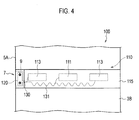
- Fig. 4 is a plan view showing the conveyor belt 1 according to the embodiment (the plan view indicated by the arrow B of Fig. 1 ).
- an endlessly shaped conveyor belt 1 is employed in a belt conveyor apparatus which is provided with a plurality of rollers 10 and a detection unit 100.
- the conveyor belt 1 is driven on the plurality of rollers 10 by means of a driving pulley (not shown).
- the rollers 10 are provided at a lower side of the endlessly shaped conveyor belt 1.
- the plurality of rollers 10 are arranged at predetermined intervals (for example, 1 m) with respect to a conveyance direction of the conveyor belt 1.
- three rollers 10 are disposed in a state in which they are arranged in a widthwise direction of the conveyor belt 1.
- the rollers 10 includes: a central roller 11 which is positioned at a center at the side of a back face 3B of a material placement face 3A of the conveyor belt 1 in the widthwise direction of the conveyor belt 1; and an end part roller 13 which is positioned at each end of the central roller 11.
- the end part roller 13 is provided so as to be inclined with respect to the central roller 11.
- the conveyor belt 1 has a mount portion 7 which is provided at a widthwise end part 5 of the conveyor belt 1 and which is mounting a processing portion 120 which constituting a detection unit 100 to be described later.
- the mount portion 7 is provided on a side end face 5A of the conveyor belt 1.
- the mount portion 7 includes a cutout 9 which is formed at the widthwise end part 5 as seen in a plan view of the conveyor belt 1 (refer to Fig. 3 ).
- the cutout 9 is comprised of: an end part parallel face 9A which is provided in substantial parallel to the widthwise end part 5 of the conveyor belt 1; and two end part orthogonal faces 9B which are provided so as to be substantially orthogonal to the widthwise end unit 5.
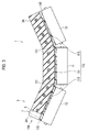
- Fig. 5 is an enlarged perspective view showing a widthwise end part 5 of a conveyor belt 1 according to the embodiment.
- Fig. 6 is a plan view showing the widthwise end part 5 of the conveyor belt 1 according to the embodiment (the plan view indicated by the arrow C of Fig. 5 ).
- Fig. 7 is a side view showing the widthwise end part 5 of the conveyor belt 1 according to the embodiment (the plan view indicated by the arrow D of Fig. 5 ).
- the detection unit 100 detects a failure of a roller 10.
- the detection unit 100 is provided with a detection portion 110, a processing portion 120, and a connector 130.
- methods of detecting a failure of a roller 10 by means of the detection unit 100 include a method of always performing measurement by means of the detection unit 100, a method of switching on or off by providing a switch unit, and a method of switching on or off from the outside (noncontact manner) by means of a remote controller or the like. It is preferable that, in a case where the detection unit 100 does not detect a failure of the roller 10, the detection unit 100 is structured to be demountable from the conveyor belt 1.
- a detection portion 110 is a pressure sensor which detects a state of a plurality of rollers 10.
- the detection portion 110 is embedded in a back face 3B of an article placement face 3A.
- the detection portion 110 like the rollers 10, is arranged in plurality at predetermined intervals (for example, 1m) with respect to a conveyance direction of the conveyor belt 1.
- three detection portions 110 are disposed in a state in which they are arranged in the widthwise direction of the conveyor belt 1.
- the detection 110 has: a central sensor 111 which is positioned upward of the central roller 11; and an end part sensor 113 which is positioned at each end of the central sensor 111, i.e., upward of an end part roller 13.
- the central sensor 111 and the end part sensor 113 are covered with a continuous covering member 115 which is continuous in the widthwise direction of the conveyor belt 1.
- the covering member 115 includes silicone or the like.
- the central sensor 111 and the end part sensor 113 are connected to each other by means of a connector 130 and a signal cable 131 to be described later. Namely, the signal cable 131 is covered with the covering member 115, together with the central sensor 111 and the end part sensor 113.
- the signal cable 131 is disposed in a wavy shape.
- a processing portion 120 is connected to the detection portion 110, and processes an output signal from the detection portion 110. Namely, the processing portion 120 is connected to the detection portion 110 via a connector 130 by routing the signal cable 131.
- the processing portion 120 is comprised of: a CPU for processing an output signal from the detection portion 110; a memory for storing the output signal from the detection portion 110; and batteries for accumulating electric power; and an antenna for making wireless communication with the outside.
- the processing portion 120 is structured to be demountable from the connector 130.
- a thickness (D1) of the processing portion 120 is smaller than a thickness (D2) of the conveyor belt 1.
- the processing portion 120 is positioned in a cutout 9 as seen in a plan view of the conveyor belt 1. Specifically, the processing portion 120 is fixed by means of a link member 25 between a placement face side plate 21 and a back face side plate 23.
- the placement face side plate 21 is arranged on the side of an article placement face 3A (on the placement face side) of the conveyor belt 1 on which a material to be conveyed is to be placed, and the cutout 9 is covered therewith.
- the back face side plate 23 is arranged at the side of a back face 3B of the conveyor belt 1 that is positioned at an opposite side of the side of the article placement face 3A, and the cutout 9 is covered therewith.
- the link member 25 links the placement face side plate 21 and the back face side plate 23 with each other.
- the link member 25 is comprised of a bolt 25A to be inserted through the placement face side plate 21, the back face side plate 23, and the processing portion 120; and a nut 25B to be spirally fitted to an end part of the bolt 25A.
- the link member 25 is inserted through the placement face side plate 21, the back face side plate 23, and the processing portion 120, whereby the processing portion 120 is positioned in the cutout 9.
- a cooling fin 27 (refer to Fig. 5 and Fig. 6 ) for thermally radiating the processing portion 120 (for example, the CPU or batteries) is provided between the placement face side plate 21 and the back face side plate 23.
- the cooling fin 27 is provided along a side part face 5A of the conveyor belt 1.
- the connector 130 is connected to the signal cable 131 for transmitting an output signal from the detection portion 110 and the processing portion 120 is connected thereto (refer to Fig. 3 and Fig. 4 ).
- the connector 130 is provided on an end part parallel face 9A (a cutout forming face) of the conveyor belt 1 forming the cutout 9.
- the connector 130 does not always need to be provided on the end part parallel face 9A, and may be provided on an end part orthogonal face 9B.
- the processing portion 120 is mounted on the mount portion 7 that is provided at the widthwise end part 5 of the conveyor belt 1. In this manner, in comparison with a case in which the detection portion 110 or the processing portion 120 is provided at each roller 10, the number of detection portions 110 or processing portions 120 is reduced, and costs of the belt conveyor apparatus can be suppressed. In addition, with a fewer detection portions 110 or processing portions 120, a failure of the detection unit 100 can be suppressed. Therefore, the belt conveyor apparatus which is provided with a number of rollers 10 is capable of reliably detecting a failure of the respective one of the rollers 10 while suppressing higher costs of the belt conveyor apparatus or the frequency of a failure of the detection unit 100.
- the mount portion 7 is provided on a side end face 5A of the conveyor belt 1. In this manner, in comparison with a case in which the mount portion 7 is provided at the side of the back face 3B of the conveyor belt 1, a failure of the processing portion 120 that is mounted on the mount portion 7 can be further suppressed and the processing portion 120 is easily demounted.
- a material drops on the article placement face 3A, whereby, when the material is placed on the article placement face 3A, an impact of the material is imparted onto the article placement face 3A.
- the mount portion 7 is provided at the side of the back face 3B of the conveyor belt 1, the failure of the processing portion 120 that is mounted on the mount portion 7 increases in probability.
- the mount portion 7 is provided on the side end face 5A of the conveyor belt 1, whereby, even in a case where an impact of a material is imparted onto the article placement face 3A, the impact of the material is hardly imparted onto the side end face 5A of the conveyor belt 1, and the failure of the processing portion 120 that is mounted on the mount portion 7 can be further suppressed.
- the processing portion 120 is positioned in the cutout 9 as seen in a plan view of the conveyor belt 1. In this manner, in comparison with a case in which the processing portion 120 is merely provided on the side end face 5A of the conveyor belt 1, the processing portion 120 never protrudes from the side end face 5A to the outside in the widthwise direction of the conveyor belt 1. Therefore, space saving can be achieved without increasing the width of the conveyor belt 1. Further, it is possible to prevent the processing portion 120 from being damaged due to the processing portion 120 coming into contact with the belt conveyor apparatus which is provided with the conveyor belt 1 (for example, a frame).
- a thickness (D1) of the processing portion 120 is smaller than a thickness (D2) of the conveyor belt 1.
- the processing portion 120 is positioned between the placement face side plate 21 and the back face side plate 23. In this manner, the processing portion 120 is covered with the placement face side plate 21 and the back face side plate 23, so that the failure of the processing portion 120 can be reduced more reliably without the abovementioned material or the belt conveyor apparatus (for example, the belt cleaner) and the processing portion 120 coming into contact with each other.
- the detection portion 110 or the signal cable 131 is provided at the side of the back face 3B of the conveyor belt 1 that comes into contact with the roller 10, and is covered with the covering member 115. In this manner, the detection portion 110 or the signal cable 131 never comes into direct contact with the roller 10. Therefore, the failure of the detection portion 110 or the signal cable 131 can be reliably reduced.
- the connector 130 is provided on the end part parallel face 9A (the cutout forming face) of the conveyor belt 1 forming the cutout 9. In this manner, the connector 130 never comes into direct contact with the roller 10. Therefore, the failure of the connector 130 can be reliably reduced.
- the signal cable 131 is disposed in a wavy shape.
- the conveyor belt 1 becomes flat on a driving puller, and is deformed on the roller 10. Since the conveyor belt 1 repeats an action of flatting or deformation, even in a case where the signal cable 131 is disposed in the wavy shape, whereby the conveyor belt 1 is deformed by a material conveyed after placed on the article placement face 3A, the signal cable 131 can cope with the shape of the conveyor belt 1. Therefore, a damage of the signal cable 131 can be suppressed.
- the cooling fin 27 is provided between the placement face side plate 21 and the back face side plate 23. In this manner, even in a case where the processing portion 120 is heated, air can be supplied into the connector 130 by means of driving of the conveyor belt 1. Therefore, the processing portion 120 (for example, the CPU or batteries) can be thermally radiated.
- the abovementioned detection portion 110 according to the embodiment may be modified as follows.
- the same constituent element as the abovementioned detection portion 110 according to the embodiment is designated by the same reference numeral, and different constituent elements are is mainly described.
- the abovementioned detection portion 110 and signal cable 131 according to the embodiment are covered with a covering member 115.
- a detection portion 110 and a signal cable 131 according to Exemplary Modifications are not covered with the covering member 115.
- Fig. 8 is a sectional view showing a conveyor belt 1A according to Exemplary Modification 1.
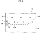
- Fig. 9 is a plan view showing the conveyor belt 1A according to Exemplary Modification 1.
- the detection portion 110A is provided at the side of a back face 3B of an article placement face 3A of the conveyor belt 1A.
- the signal cable 131A is provided at the side of the back face 3B of the article placement face 3A of the conveyor belt 1A. That is, as described above, the detection portion 110A and the signal cable 131A are not covered with the covering member 115.
- a belt conveyor apparatus which is provided with a number of rollers 10 is capable of reliably detecting a failure of a respective one of the rollers 10 while suppressing higher costs of the belt conveyor apparatus or the frequency of a failure of a detection unit 100A.
- Fig. 10 is a sectional view showing a conveyor belt 1B according to Exemplary Modification 2.
- Fig. 11 is a plan view showing the conveyor belt 1B according to Exemplary Modification 2.
- the detection portion 110A is embedded in the conveyor belt 1B.
- the signal cable 131B is embedded in the back face 3B of the article placement face 3A.
- a belt conveyor apparatus which is provided with a number of rollers 10 is capable of reliably detecting a failure of a respective one of the rollers 10 while suppressing higher costs of the belt conveyor apparatus or a frequency of a failure of a detection unit 100.
- the detection portion 110A and the signal cable 131B are embedded in the conveyor belt 1B. In this manner, the detection portion 110A or the signal cable 131 never come into direct contact with the roller 10. Therefore, failures of the detection portion 110A or the signal cable 131 can be reliably reduced.
- the embodiment of the present invention can be modified as follows.
- the shape or structure and arrangement or the like of the roller 10 or the detection unit 100 are not limited in particular, and can be appropriately selected according to purposes.
- the detection portion 110 is embedded in the side of the back face 3B of the article placement face 3A of the conveyor belt 1
- the detection unit may be fixed to the side of the back face 3B without being limitative thereto.
- three detection portions 110 are disposed in a state in which they are arranged in the widthwise direction of the conveyor belt 1, one detection unit may be disposed along the widthwise direction of the conveyor belt 1 without being limitative thereto.
- the detection portion 110 is a pressure sensor, it is a matter of course that the detection portion 110 may be a temperature sensor or a distortion sensor employing thermocouples or the like, a shear force sensor, a magnetic sensor, an acceleration sensor, or a sonic sensor and the like.
- the processing portion 120 may be merely fixed to the widthwise end part 5 (a side end face 5A) without being limitative thereto.
- the connector 130 is provided on the side end face 5A, thereby facilitating demounting of the processing portion 120.
- the processing portion 120 may be protected by means of a cabinet or the like for housing the processing portion 120.
- the processing portion 120 is comprised of a CPU, a memory, batteries, and an antenna
- the processing portion 120 may be a structure which is capable of storing an output signal from the detection portion 110 by means of at least only a memory without being limitative thereto.
- electric power may be supplied from the outside (for example, by means of radio communication or an electromagnetic force, or by provision of electric wires).
- an output signal from the detection portion 110 may be taken out by making the processing portion 120 (memory) demountable. At this time, driving of the conveyor belt 1 is stopped.
- link member 25 is comprised of the bolt 25A and the nut 25B, it is sufficient if the processing portion 120 can be secured by linking the placement face side plate 21 and the back side plate 23 with each other, without being limitative thereto.
- the signal cable 131 is disposed in a wavy shape, it is a matter of course that the signal cable may be disposed in a linear shape without being limitative thereto.
- the present invention is applicable in a conveyor belt of a belt conveyor which is provided with a number of rollers for conveying transportation materials such as earth and soil or coal, since a detection unit for processing an output signal from a sensor for detecting a rotational failure is provided at a widthwise end part of the conveyor belt, thereby making it possible to suppress higher costs of the belt conveyor apparatus or a frequency of a failure of the detection unit.
- 1, 1A, 1B conveyor belt
- 3A material placement face
- 3B back face
- 5 widthwise end part
- 5A side end face
- 7 mount portion
- 9A end part parallel face
- 9B end part orthogonal face
- 10 roller
- 11 central roller
- 13 end part roller
- 21 placement face side plate
- 23 back face side plate
- 25 link member
- 25A bolt
- 25B nut
- 27 cooling fin
- 110,110A,1108 detection portion
- 111 central sensor
- 113 end part sensor
- 115 covering member
- 120 processing portion
- 130 connector
- 131,131A,131B signal cable
Landscapes
- Control Of Conveyors (AREA)
- Structure Of Belt Conveyors (AREA)
- Belt Conveyors (AREA)
Abstract
Description
- The present invention relates to a conveyor belt which is employed in a belt conveyor apparatus which is provided with a plurality of rollers.
- Conventionally, in a belt conveyor apparatus for conveying materials (transportation materials such as earth and sand or coal), an endlessly shaped conveyor belt is driven on a plurality of rollers by means of a driving pulley. The plurality of rollers is provided at a lower side of the conveyor belt. Specifically, a carrier roller is provided at a back side of an article placement face, and a return roller is provided at an opposite side of the carrier roller.
- In such a belt conveyor apparatus, each of the rollers needs to always smoothly rotate in order to prevent damage of the conveyor belt or the like. In particular, if a conveyance distance is long (for example, 10 km or more), since a huge amount of rollers are provided, a method of speedily and easily detecting a roller at which a failure such as a rotational failure occurs is mandatory.
- Therefore, it is known that there is provided a belt conveyor apparatus in which a detection unit including a sensor for detecting a rotational failure of a roller and a processing portion such as a CPU for processing an output signal from the sensor are provided at their respective rollers (for example, Patent Document 1).
-
- Patent Document 1: Japanese Patent Application Laid-open No.
2005-24441 Fig. 2 ) - The conventional belt conveyor apparatus described above has entailed the following problem. That is, since a detection unit for detecting a rotational failure of a roller is provided at each roller, there has been a problem that costs of the belt conveyor apparatus increase.
- In addition, since a sensor and a processing portion are provided at their respective rollers, there has been a problem that a frequency of a failure of a detection unit increases.
- Therefore, it is an object of the present invention to provide a conveyor belt which is capable of reliably detecting a failure of a respective one of rollers while suppressing higher costs of a belt conveyor apparatus or a frequency of a failure of a detection unit in the belt conveyor apparatus which is provided with a number of rollers.
- To solve the above problem, the present invention has following features. Firstly, the feature of the present invention is summarized as a conveyor belt (conveyor belt 1) employed in a belt conveyor apparatus which including: a plurality of rollers (rollers 10); a detection portion (detection portion 110) configured to detect a state of the rollers; and a processing portion (processing portion 120) configured to connect to the detection portion, for processing an output signal from the detection portion, wherein the conveyor belt has a mount portion (mount portion 7) on which the processing portion is mounted, the mount portion is provided at a widthwise end part of the conveyor belt.
- According to such features, a processing portion is mounted on a mount portion which is provided at a widthwise end part of a conveyor belt. In this manner, in comparison with a case in which a detection portion or the processing portion is provided at each roller, the number of detection portions or processing portions is reduced and costs of the belt conveyor apparatus can be suppressed. In addition, with a fewer detection portions or processing portions, a failure of a detection unit can be suppressed. Therefore, the belt conveyor apparatus which is provided with a number of rollers is capable of reliably detecting a failure of the respective one of the rollers while suppressing higher costs of the belt conveyor apparatus or the frequency of the failure of the detection unit.
- A second feature of the present invention according to the first feature is summarized as that the mount portion includes a cutout (cutout 9) which is formed at the widthwise end part as seen in a plan view of the conveyor belt; and the processing portion is positioned in the cutout as seen in the plan view of the conveyor belt.
- A third feature of the present invention according to the first or second feature is summarized as that a thickness (D1) of the processing portion is smaller than a thickness (D2) of the conveyor belt.
- A fourth feature of the present invention according to the third feature is summarized as the conveyor belt, including: a placement face side plate (placement face side plate 21) arranged at a placement face side (
material placement face 3A side) of the conveyor belt on which an article to be conveyed is to be placed, the placement face side plate covering the cutout; a back face side plate (back face side plate 23) arranged at a back face side (backface 3B side) of the conveyor belt that is positioned at an opposite side of the placement face side, the back face side plate covering the cutout; and a link member (link member 25) configured to link the placement face side plate and the back face side plate with each other, wherein the processing portion is positioned between the placement face side plate and the back face side plate. - A fifth feature of the present invention according to any one of the first to fourth features is summarized as that the detection portion is provided at the back face side of the conveyor belt that comes into contact with the rollers and the detection portion is covered with a covering member (covering member 115).
- A sixth feature of the present invention according to any one of the first to fifth features is summarized as that the detection portion is embedded in the conveyor belt.
- A seventh feature of the present invention according to any one of the first to sixth features is summarized as that a connector (connector 130) which is connected to a signal cable for transmitting an output signal from the detection portion and to which the processing portion is connected, is provided at the widthwise end part.
- A eighth feature of the present invention according to the seventh feature is summarized as that the connector is provided on a cutout forming face (e.g. end part parallel face 9a) of the conveyor belt, the cutout forming face forming the cutout.
- According to the present invention, it is possible to provide a conveyor belt capable of reliably detecting a failure of a respective one of rollers while suppressing higher costs of a belt conveyor apparatus or a frequency of a failure of a detection unit in the belt conveyor apparatus which is provided with a number of rollers.
-
- [
Fig. 1 ]
Fig. 1 is a perspective view showing aconveyor belt 1 according to the embodiment (the perspective view of a top face side). - [
Fig. 2 ]
Fig. 2 is a perspective view showing theconveyor belt 1 according to the embodiment (the perspective view of a bottom face side). - [
Fig. 3 ]
Fig. 3 is a sectional view showing theconveyor belt 1 according to the embodiment (the sectional view taken along the line A-A ofFig. 1 ). - [
Fig. 4 ]
Fig. 4 is a plan view showing theconveyor belt 1 according to the embodiment (the plan view indicated by the arrow B ofFig. 1 ) - [
Fig. 5 ]
Fig. 5 is an enlarged perspective view showing a widthwise end part 5 of theconveyor belt 1 according to the embodiment. - [
Fig. 6 ]
Fig. 6 is a plan view showing the widthwise end part 5 of theconveyor belt 1 according to the embodiment (the plan view indicated by the arrow C ofFig. 5 ). - [
Fig. 7 ]
Fig. 7 is a plan view showing the widthwise end part 5 of theconveyor belt 1 according to the embodiment (the plan view indicated by the arrow D ofFig. 5 ). - [
Fig. 8 ]
Fig. 8 is a sectional view showing aconveyor belt 1A according toExemplary Modification 1. - [
Fig. 9 ]
Fig. 9 is a plan view showing theconveyor belt 1A according toExemplary Modification 1. - [
Fig. 10 ]
Fig. 10 is a sectional view showing aconveyor belt 1B according to Exemplary Modification 2. - [
Fig. 11 ]
Fig. 11 is a plan view showing theconveyor belt 1B according to Exemplary Modification 2. - Next, an embodiment of a conveyor belt according to the present invention will be described with reference to the drawings. Specifically, descriptions will be furnished with respect to (1) Structure of Conveyor Belt, (2) Structure of Detection Unit, (3) Functions and Advantageous Effects, (4) Exemplary Modifications, and (5) Other Embodiments
- In the description of the drawings that follows, the same or similar constituent elements are designated by the same or similar reference numerals. However, it should be kept in mind that: the drawings are merely schematic; and rates of dimensions each are different from an actual one.
- Therefore, specific dimensions or the like should be determined in consideration of the following description. In addition, it is a matter of course that portions with their different dimensional interrelationships or rates are included in the drawings.
- First, a structure of a
conveyor belt 1 according to the embodiment will be described with reference to the drawings.Fig. 1 andFig. 2 are perspective views showing theconveyor belt 1 according to the embodiment.Fig. 3 is a sectional view showing theconveyor belt 1 according to the embodiment (the sectional view taken along the line A-A ofFig. 1 ).Fig. 4 is a plan view showing theconveyor belt 1 according to the embodiment (the plan view indicated by the arrow B ofFig. 1 ). - As shown in
Fig. 1 to Fig. 4 , an endlessly shapedconveyor belt 1 is employed in a belt conveyor apparatus which is provided with a plurality ofrollers 10 and adetection unit 100. Theconveyor belt 1 is driven on the plurality ofrollers 10 by means of a driving pulley (not shown). - The
rollers 10 are provided at a lower side of the endlessly shapedconveyor belt 1. The plurality ofrollers 10 are arranged at predetermined intervals (for example, 1 m) with respect to a conveyance direction of theconveyor belt 1. In addition, threerollers 10 are disposed in a state in which they are arranged in a widthwise direction of theconveyor belt 1. - Specifically, the
rollers 10 includes: acentral roller 11 which is positioned at a center at the side of aback face 3B of amaterial placement face 3A of theconveyor belt 1 in the widthwise direction of theconveyor belt 1; and anend part roller 13 which is positioned at each end of thecentral roller 11. Theend part roller 13 is provided so as to be inclined with respect to thecentral roller 11. - Herein, the
conveyor belt 1 has amount portion 7 which is provided at a widthwise end part 5 of theconveyor belt 1 and which is mounting aprocessing portion 120 which constituting adetection unit 100 to be described later. Specifically, themount portion 7 is provided on aside end face 5A of theconveyor belt 1. Themount portion 7 includes acutout 9 which is formed at the widthwise end part 5 as seen in a plan view of the conveyor belt 1 (refer toFig. 3 ). - The
cutout 9 is comprised of: an end partparallel face 9A which is provided in substantial parallel to the widthwise end part 5 of theconveyor belt 1; and two end part orthogonal faces 9B which are provided so as to be substantially orthogonal to the widthwise end unit 5. - Next, a
detection unit 100 according to the embodiment will be described with reference toFig. 1 to Fig. 7 .Fig. 5 is an enlarged perspective view showing a widthwise end part 5 of aconveyor belt 1 according to the embodiment.Fig. 6 is a plan view showing the widthwise end part 5 of theconveyor belt 1 according to the embodiment (the plan view indicated by the arrow C ofFig. 5 ).Fig. 7 is a side view showing the widthwise end part 5 of theconveyor belt 1 according to the embodiment (the plan view indicated by the arrow D ofFig. 5 ). - As shown in
Fig. 1 to Fig. 7 , thedetection unit 100 detects a failure of aroller 10. Specifically, thedetection unit 100 is provided with adetection portion 110, aprocessing portion 120, and aconnector 130. - Here, for example, methods of detecting a failure of a
roller 10 by means of thedetection unit 100 include a method of always performing measurement by means of thedetection unit 100, a method of switching on or off by providing a switch unit, and a method of switching on or off from the outside (noncontact manner) by means of a remote controller or the like. It is preferable that, in a case where thedetection unit 100 does not detect a failure of theroller 10, thedetection unit 100 is structured to be demountable from theconveyor belt 1. - A
detection portion 110 is a pressure sensor which detects a state of a plurality ofrollers 10. Thedetection portion 110 is embedded in aback face 3B of anarticle placement face 3A. Thedetection portion 110, like therollers 10, is arranged in plurality at predetermined intervals (for example, 1m) with respect to a conveyance direction of theconveyor belt 1. In addition, threedetection portions 110 are disposed in a state in which they are arranged in the widthwise direction of theconveyor belt 1. - Specifically, the
detection 110 has: acentral sensor 111 which is positioned upward of thecentral roller 11; and anend part sensor 113 which is positioned at each end of thecentral sensor 111, i.e., upward of anend part roller 13. - The
central sensor 111 and the end part sensor 113 (the detection portion 110) are covered with acontinuous covering member 115 which is continuous in the widthwise direction of theconveyor belt 1. The coveringmember 115 includes silicone or the like. - The
central sensor 111 and theend part sensor 113 are connected to each other by means of aconnector 130 and asignal cable 131 to be described later. Namely, thesignal cable 131 is covered with the coveringmember 115, together with thecentral sensor 111 and theend part sensor 113. Thesignal cable 131 is disposed in a wavy shape. - A
processing portion 120 is connected to thedetection portion 110, and processes an output signal from thedetection portion 110. Namely, theprocessing portion 120 is connected to thedetection portion 110 via aconnector 130 by routing thesignal cable 131. - The
processing portion 120 is comprised of: a CPU for processing an output signal from thedetection portion 110; a memory for storing the output signal from thedetection portion 110; and batteries for accumulating electric power; and an antenna for making wireless communication with the outside. Theprocessing portion 120 is structured to be demountable from theconnector 130. - A thickness (D1) of the
processing portion 120 is smaller than a thickness (D2) of theconveyor belt 1. Theprocessing portion 120 is positioned in acutout 9 as seen in a plan view of theconveyor belt 1. Specifically, theprocessing portion 120 is fixed by means of alink member 25 between a placement face side plate 21 and a backface side plate 23. - The placement face side plate 21 is arranged on the side of an
article placement face 3A (on the placement face side) of theconveyor belt 1 on which a material to be conveyed is to be placed, and thecutout 9 is covered therewith. The backface side plate 23 is arranged at the side of aback face 3B of theconveyor belt 1 that is positioned at an opposite side of the side of thearticle placement face 3A, and thecutout 9 is covered therewith. - The
link member 25 links the placement face side plate 21 and the backface side plate 23 with each other. Thelink member 25 is comprised of abolt 25A to be inserted through the placement face side plate 21, the backface side plate 23, and theprocessing portion 120; and anut 25B to be spirally fitted to an end part of thebolt 25A. Thelink member 25 is inserted through the placement face side plate 21, the backface side plate 23, and theprocessing portion 120, whereby theprocessing portion 120 is positioned in thecutout 9. - Herein, a cooling fin 27 (refer to
Fig. 5 andFig. 6 ) for thermally radiating the processing portion 120 (for example, the CPU or batteries) is provided between the placement face side plate 21 and the backface side plate 23. The coolingfin 27 is provided along aside part face 5A of theconveyor belt 1. - The
connector 130 is connected to thesignal cable 131 for transmitting an output signal from thedetection portion 110 and theprocessing portion 120 is connected thereto (refer toFig. 3 andFig. 4 ). Theconnector 130 is provided on an end partparallel face 9A (a cutout forming face) of theconveyor belt 1 forming thecutout 9. Theconnector 130 does not always need to be provided on the end partparallel face 9A, and may be provided on an end partorthogonal face 9B. - In the embodiment, the
processing portion 120 is mounted on themount portion 7 that is provided at the widthwise end part 5 of theconveyor belt 1. In this manner, in comparison with a case in which thedetection portion 110 or theprocessing portion 120 is provided at eachroller 10, the number ofdetection portions 110 or processingportions 120 is reduced, and costs of the belt conveyor apparatus can be suppressed. In addition, with afewer detection portions 110 or processingportions 120, a failure of thedetection unit 100 can be suppressed. Therefore, the belt conveyor apparatus which is provided with a number ofrollers 10 is capable of reliably detecting a failure of the respective one of therollers 10 while suppressing higher costs of the belt conveyor apparatus or the frequency of a failure of thedetection unit 100. - In the embodiment, the
mount portion 7 is provided on aside end face 5A of theconveyor belt 1. In this manner, in comparison with a case in which themount portion 7 is provided at the side of theback face 3B of theconveyor belt 1, a failure of theprocessing portion 120 that is mounted on themount portion 7 can be further suppressed and theprocessing portion 120 is easily demounted. - Specifically, a material drops on the
article placement face 3A, whereby, when the material is placed on thearticle placement face 3A, an impact of the material is imparted onto thearticle placement face 3A. Thus, in a case where themount portion 7 is provided at the side of theback face 3B of theconveyor belt 1, the failure of theprocessing portion 120 that is mounted on themount portion 7 increases in probability. On the other hand, themount portion 7 is provided on theside end face 5A of theconveyor belt 1, whereby, even in a case where an impact of a material is imparted onto thearticle placement face 3A, the impact of the material is hardly imparted onto theside end face 5A of theconveyor belt 1, and the failure of theprocessing portion 120 that is mounted on themount portion 7 can be further suppressed. - In the embodiment, the
processing portion 120 is positioned in thecutout 9 as seen in a plan view of theconveyor belt 1. In this manner, in comparison with a case in which theprocessing portion 120 is merely provided on theside end face 5A of theconveyor belt 1, theprocessing portion 120 never protrudes from theside end face 5A to the outside in the widthwise direction of theconveyor belt 1. Therefore, space saving can be achieved without increasing the width of theconveyor belt 1. Further, it is possible to prevent theprocessing portion 120 from being damaged due to theprocessing portion 120 coming into contact with the belt conveyor apparatus which is provided with the conveyor belt 1 (for example, a frame). - In the embodiment, a thickness (D1) of the
processing portion 120 is smaller than a thickness (D2) of theconveyor belt 1. Thus, theprocessing portion 120 never protrudes from thearticle placement face 3A of theconveyor belt 1. Therefore, the failure of theprocessing portion 120 can be further suppressed without coming into contact between a material which is conveyed after placed on thearticle placement face 3A or the belt conveyor apparatus (for example, a belt cleaner for cleaning a dirt adhering to the material placemen face 3A) or the like and theprocessing portion 120. - In the embodiment, the
processing portion 120 is positioned between the placement face side plate 21 and the backface side plate 23. In this manner, theprocessing portion 120 is covered with the placement face side plate 21 and the backface side plate 23, so that the failure of theprocessing portion 120 can be reduced more reliably without the abovementioned material or the belt conveyor apparatus (for example, the belt cleaner) and theprocessing portion 120 coming into contact with each other. - In the embodiment, the link member 25 (the
bolt 25A) is inserted through the placement face side plate 21, the backface side plate 23, and theprocessing portion 120. In this manner, theprocessing portion 120 is easily demounted, and maintenance capability is improved. In addition, it is possible to suppress theprocessing portion 120 from colliding with the end partparallel face 9A or the end partorthogonal face 9B due to movement of theprocessing portion 120 in thecutout 9, and the failure of theprocessing portion 120 can be reduced more reliably. - In the embodiment, the
detection portion 110 or thesignal cable 131 is provided at the side of theback face 3B of theconveyor belt 1 that comes into contact with theroller 10, and is covered with the coveringmember 115. In this manner, thedetection portion 110 or thesignal cable 131 never comes into direct contact with theroller 10. Therefore, the failure of thedetection portion 110 or thesignal cable 131 can be reliably reduced. - In the embodiment, the
connector 130 is provided on the end partparallel face 9A (the cutout forming face) of theconveyor belt 1 forming thecutout 9. In this manner, theconnector 130 never comes into direct contact with theroller 10. Therefore, the failure of theconnector 130 can be reliably reduced. - In the embodiment, the
signal cable 131 is disposed in a wavy shape. Theconveyor belt 1 becomes flat on a driving puller, and is deformed on theroller 10. Since theconveyor belt 1 repeats an action of flatting or deformation, even in a case where thesignal cable 131 is disposed in the wavy shape, whereby theconveyor belt 1 is deformed by a material conveyed after placed on thearticle placement face 3A, thesignal cable 131 can cope with the shape of theconveyor belt 1. Therefore, a damage of thesignal cable 131 can be suppressed. - In the embodiment, the cooling
fin 27 is provided between the placement face side plate 21 and the backface side plate 23. In this manner, even in a case where theprocessing portion 120 is heated, air can be supplied into theconnector 130 by means of driving of theconveyor belt 1. Therefore, the processing portion 120 (for example, the CPU or batteries) can be thermally radiated. - The
abovementioned detection portion 110 according to the embodiment may be modified as follows. The same constituent element as theabovementioned detection portion 110 according to the embodiment is designated by the same reference numeral, and different constituent elements are is mainly described. - The
abovementioned detection portion 110 andsignal cable 131 according to the embodiment are covered with a coveringmember 115. On the other hand, adetection portion 110 and asignal cable 131 according to Exemplary Modifications are not covered with the coveringmember 115. - First, structures of a
detection portion 110A and asignal cable 131A according toExemplary Modification 1 will be described with reference to the drawings.Fig. 8 is a sectional view showing aconveyor belt 1A according toExemplary Modification 1.Fig. 9 is a plan view showing theconveyor belt 1A according toExemplary Modification 1. - As shown in
Fig. 8 andFig. 9 , thedetection portion 110A is provided at the side of aback face 3B of anarticle placement face 3A of theconveyor belt 1A. In addition, thesignal cable 131A is provided at the side of theback face 3B of thearticle placement face 3A of theconveyor belt 1A. That is, as described above, thedetection portion 110A and thesignal cable 131A are not covered with the coveringmember 115. - In
Exemplary Modification 1, as is the case with the abovementioned functions and advantageous effects of the embodiment, a belt conveyor apparatus which is provided with a number ofrollers 10 is capable of reliably detecting a failure of a respective one of therollers 10 while suppressing higher costs of the belt conveyor apparatus or the frequency of a failure of a detection unit 100A. - Next, structures of a
detection portion 110B and asignal cable 131B according to Exemplary Modification 2 will be described with reference to the drawings.Fig. 10 is a sectional view showing aconveyor belt 1B according to Exemplary Modification 2.Fig. 11 is a plan view showing theconveyor belt 1B according to Exemplary Modification 2. - As shown in
Fig. 10 andFig. 11 , thedetection portion 110A is embedded in theconveyor belt 1B. In addition, thesignal cable 131B is embedded in theback face 3B of thearticle placement face 3A. - In Exemplary Modification 2, as is the case with the abovementioned functions and advantageous effects of the embodiment, a belt conveyor apparatus which is provided with a number of
rollers 10 is capable of reliably detecting a failure of a respective one of therollers 10 while suppressing higher costs of the belt conveyor apparatus or a frequency of a failure of adetection unit 100. - In particular, the
detection portion 110A and thesignal cable 131B are embedded in theconveyor belt 1B. In this manner, thedetection portion 110A or thesignal cable 131 never come into direct contact with theroller 10. Therefore, failures of thedetection portion 110A or thesignal cable 131 can be reliably reduced. - As described above, while the contents of the present invention were disclosed through the embodiment of the present invention, it should not be understood that discussions and drawings forming a part of this disclosure limit the present invention. From this disclosure, a variety of substitutive embodiments, examples, and operational techniques would be self-evident to one skilled in the art.
- For example, the embodiment of the present invention can be modified as follows. Specifically, the shape or structure and arrangement or the like of the
roller 10 or thedetection unit 100 are not limited in particular, and can be appropriately selected according to purposes. - While the embodiment described that the
detection portion 110 is embedded in the side of theback face 3B of thearticle placement face 3A of theconveyor belt 1, the detection unit may be fixed to the side of theback face 3B without being limitative thereto. - While the embodiment described that three
detection portions 110 are disposed in a state in which they are arranged in the widthwise direction of theconveyor belt 1, one detection unit may be disposed along the widthwise direction of theconveyor belt 1 without being limitative thereto. - While the embodiment described that the
detection portion 110 is a pressure sensor, it is a matter of course that thedetection portion 110 may be a temperature sensor or a distortion sensor employing thermocouples or the like, a shear force sensor, a magnetic sensor, an acceleration sensor, or a sonic sensor and the like. - While the embodiment described that the
processing portion 120 is positioned in thecutout 9 as seen in a plan view of theconveyor belt 1, theprocessing portion 120 may be merely fixed to the widthwise end part 5 (aside end face 5A) without being limitative thereto. In this case, theconnector 130 is provided on theside end face 5A, thereby facilitating demounting of theprocessing portion 120. In addition, theprocessing portion 120 may be protected by means of a cabinet or the like for housing theprocessing portion 120. - While the embodiment described that the
processing portion 120 is comprised of a CPU, a memory, batteries, and an antenna, theprocessing portion 120 may be a structure which is capable of storing an output signal from thedetection portion 110 by means of at least only a memory without being limitative thereto. - For example, in a case where batteries are not provided, electric power may be supplied from the outside (for example, by means of radio communication or an electromagnetic force, or by provision of electric wires). In addition, in a case where an antenna is not provided, an output signal from the
detection portion 110 may be taken out by making the processing portion 120 (memory) demountable. At this time, driving of theconveyor belt 1 is stopped. - While the embodiment described that the
link member 25 is comprised of thebolt 25A and thenut 25B, it is sufficient if theprocessing portion 120 can be secured by linking the placement face side plate 21 and theback side plate 23 with each other, without being limitative thereto. - While the embodiment described that the
signal cable 131 is disposed in a wavy shape, it is a matter of course that the signal cable may be disposed in a linear shape without being limitative thereto. - Thus, it is a matter of course that the present invention includes a variety of embodiments or the like which are not described herein. Therefore, technical scope of the present invention is defined merely by specific matters of the invention according to scope of claims which are reasonable from the above description.
- The entire contents of Japanese Patent Application No.
2009-002923 (filed on January 8, 2009 - As described above, the present invention is applicable in a conveyor belt of a belt conveyor which is provided with a number of rollers for conveying transportation materials such as earth and soil or coal, since a detection unit for processing an output signal from a sensor for detecting a rotational failure is provided at a widthwise end part of the conveyor belt, thereby making it possible to suppress higher costs of the belt conveyor apparatus or a frequency of a failure of the detection unit.
- 1, 1A, 1B: conveyor belt, 3A: material placement face, 3B: back face, 5: widthwise end part, 5A: side end face, 7: mount portion, 9A: end part parallel face (cutoff forming face), 9B: end part orthogonal face (cutoff forming face), 10: roller, 11: central roller, 13: end part roller, 21: placement face side plate, 23: back face side plate, 25: link member, 25A: bolt, 25B: nut, 27: cooling fin, 100,100A,100B: detection unit, 110,110A,1108: detection portion, 111: central sensor, 113:end part sensor, 115: covering member, 120: processing portion, 130: connector, 131,131A,131B: signal cable
Claims (8)
- A conveyor belt employed in a belt conveyor apparatus which comprises:a plurality of rollers;a detection portion configured to detect a state of the rollers; anda processing portion configured to connect to the detection portion, for processing an output signal from the detection portion, whereinthe conveyor belt has a mount portion on which the processing portion is mounted,the mount portion is provided at a widthwise end part of the conveyor belt.
- The conveyor belt according to claim 1, wherein:the mount portion includes a cutout which is formed at the widthwise end part as seen in a plan view of the conveyor belt; andthe processing portion is positioned in the cutout as seen in the plan view of the conveyor belt.
- The conveyor belt according to claim 1 or 2, wherein a thickness of the processing portion is smaller than a thickness of the conveyor belt.
- The conveyor belt according to claim 3, comprising:a placement face side plate arranged at a placement face side of the conveyor belt on which an article to be conveyed is to be placed, the placement face side plate covering the cutout;a back face side plate arranged at a back face side of the conveyor belt that is positioned at an opposite side of the placement face side, the back face side plate covering the cutout, anda link member configured to link the placement face side plate and the back face side plate with each other,wherein the processing portion is positioned between the placement face side plate and the back face side plate.
- The conveyor belt according to any one of claims 1 to 4, wherein
the detection portion is provided at the back face side of the conveyor belt that comes into contact with the rollers and
the detection portion is covered with a covering member. - The conveyor belt according to any one of claims 1 to 5, wherein the detection portion is embedded in the conveyor belt.
- The conveyor belt according to any one of claims 1 to 6, wherein
a connector which is connected to a signal cable for transmitting an output signal from the detection portion and to which the processing portion is connected, is provided at the widthwise end part. - The conveyor belt according to claims 7, wherein
the connector is provided on a cutout forming face of the conveyor belt, the cutout forming face forming the cutout.
Applications Claiming Priority (2)
| Application Number | Priority Date | Filing Date | Title |
|---|---|---|---|
| JP2009002923A JP2010159137A (en) | 2009-01-08 | 2009-01-08 | Conveyor belt |
| PCT/JP2010/000090 WO2010079764A1 (en) | 2009-01-08 | 2010-01-08 | Conveyor belt |
Publications (3)
| Publication Number | Publication Date |
|---|---|
| EP2386505A1 true EP2386505A1 (en) | 2011-11-16 |
| EP2386505A4 EP2386505A4 (en) | 2015-05-13 |
| EP2386505B1 EP2386505B1 (en) | 2016-11-02 |
Family
ID=42316530
Family Applications (1)
| Application Number | Title | Priority Date | Filing Date |
|---|---|---|---|
| EP10729184.1A Not-in-force EP2386505B1 (en) | 2009-01-08 | 2010-01-08 | Conveyor belt |
Country Status (6)
| Country | Link |
|---|---|
| US (1) | US20120012443A1 (en) |
| EP (1) | EP2386505B1 (en) |
| JP (1) | JP2010159137A (en) |
| CN (1) | CN102272022A (en) |
| AU (1) | AU2010204030A1 (en) |
| WO (1) | WO2010079764A1 (en) |
Cited By (6)
| Publication number | Priority date | Publication date | Assignee | Title |
|---|---|---|---|---|
| CN103112700A (en) * | 2013-01-17 | 2013-05-22 | 辽宁科技大学 | Long-distance belt conveyor roller fault detecting device |
| RU2561492C1 (en) * | 2014-05-26 | 2015-08-27 | Федеральное государственное бюджетное образовательное учреждение высшего профессионального образования "Кузбасский государственный технический университет имени Т.Ф. Горбачева" (КузГТУ) | Detection of belt conveyor rollers with increased resistance to rotation |
| WO2019206505A1 (en) * | 2018-04-27 | 2019-10-31 | Voith Patent Gmbh | Conveyor belt having sensors and/or transponders and method for mounting sensors and/or transponders in the conveyor belt |
| WO2021058682A1 (en) * | 2019-09-26 | 2021-04-01 | Otto-Von-Guericke-Universität Magdeburg | Method and measurement system for detecting and localizing incorrect positioning of support rollers in belt conveyor installations |
| WO2021151577A1 (en) * | 2020-01-28 | 2021-08-05 | Voith Patent Gmbh | Belt conveyor having a sensor apparatus and sensor apparatus and method for detecting operating states of load-bearing rollers |
| CN116912186A (en) * | 2023-07-05 | 2023-10-20 | 山东能源集团鲁西矿业有限公司 | Method for arranging and detecting iron foreign matters in iron ore belt conveying process |
Families Citing this family (15)
| Publication number | Priority date | Publication date | Assignee | Title |
|---|---|---|---|---|
| WO2012060999A1 (en) | 2010-11-02 | 2012-05-10 | Laitram, L.L.C. | Conveyor system, belt, and method using accelerometers |
| DE102012107847A1 (en) * | 2012-08-27 | 2014-02-27 | Thyssenkrupp Resource Technologies Gmbh | Testing device e.g. support plate for testing condition of conveyer plant, has detection units to detect state of conveyer system components, where conveyer plant is provided with conveyer belt which forms upper and lower flanges |
| JP6164182B2 (en) * | 2014-09-16 | 2017-07-19 | Jfeスチール株式会社 | Abnormality detection method for belt conveyor |
| DE102015209357A1 (en) * | 2015-05-21 | 2016-11-24 | Ifm Electronic Gmbh | Device for belt tear monitoring in a conveyor belt |
| CN105416989A (en) * | 2015-12-16 | 2016-03-23 | 苏州频发机电科技有限公司 | Intelligent belt conveyor |
| DE102017206002A1 (en) * | 2017-04-07 | 2018-10-11 | Contitech Transportbandsysteme Gmbh | Taschenfördergurtanlage |
| DE102017205961B4 (en) | 2017-04-07 | 2025-01-23 | Contitech Transportbandsysteme Gmbh | pocket conveyor belt |
| DE102017206980A1 (en) * | 2017-04-26 | 2018-10-31 | Contitech Antriebssysteme Gmbh | Carrying, pulling or driving element made of elastomeric material with embedded electronic components |
| CN107235291A (en) * | 2017-07-24 | 2017-10-10 | 合肥星袖机械科技有限公司 | A kind of streamline anti-skidding heat-radiating type self-interacting type conveyer belt device |
| BE1027257B1 (en) * | 2019-10-21 | 2020-12-01 | Thyssenkrupp Ag | Conveyor belt system with data transmission integrated in the conveyor belt |
| WO2021078702A1 (en) | 2019-10-21 | 2021-04-29 | Thyssenkrupp Industrial Solutions Ag | Conveyor belt system having data transmission integrated in the conveyor belt |
| CN113200287B (en) * | 2021-05-17 | 2023-01-31 | 福建龙净环保股份有限公司 | Pipe belt machine inspection device, pipe belt machine, inspection robot and pipe belt machine inspection method |
| CN115489931B (en) * | 2021-06-17 | 2024-09-24 | 安徽丹凤电子材料股份有限公司 | Quick positioning device and quick positioning method for electronic material processing |
| EP4504625A4 (en) * | 2022-04-05 | 2026-03-18 | Flexible Steel Lacing Co | MONITORING SYSTEM FOR CONVEYOR BELT SUPPLEMENTS |
| WO2024044172A1 (en) | 2022-08-23 | 2024-02-29 | Flexible Steel Lacing Company | Conveyor belt cleaner blade wear monitoring system |
Family Cites Families (18)
| Publication number | Priority date | Publication date | Assignee | Title |
|---|---|---|---|---|
| AU467441B2 (en) * | 1972-04-20 | 1975-12-04 | Continental Gummi-Werke Aktiengesellschaft | Control device for conveyor belts |
| JPS5320787U (en) * | 1976-07-31 | 1978-02-22 | ||
| JPH0714249Y2 (en) * | 1989-01-25 | 1995-04-05 | 三菱重工業株式会社 | Conveyor abnormality diagnosis device |
| US6186318B1 (en) * | 1996-11-18 | 2001-02-13 | Pax Products, Inc. | Endless belt coveyor unit for a stamping press |
| DE19911640B4 (en) * | 1999-03-16 | 2006-02-16 | Vattenfall Europe Mining Ag | Method and determination of installation errors at carrying roller stations and complete supporting frames in belt conveyors |
| US6516943B2 (en) * | 2001-04-12 | 2003-02-11 | 3M Innovative Properties Company | Conveyor belt splice cover, and methods |
| JP2005024441A (en) | 2003-07-04 | 2005-01-27 | Ntn Corp | Abnormality inspection system for bearing with ic tag sensor |
| JP2006052039A (en) * | 2004-08-10 | 2006-02-23 | Bridgestone Corp | Conveyor belt monitoring system |
| DE102005021627A1 (en) * | 2005-05-06 | 2006-11-16 | Rwe Power Ag | Method for monitoring the band alignment and / or the tape running of a belt conveyor and belt conveyor |
| DE102005054481A1 (en) * | 2005-11-16 | 2007-05-24 | Phoenix Conveyor Belt Systems Gmbh | Conveyor belt with exchangeable segments |
| CN2937035Y (en) * | 2006-01-27 | 2007-08-22 | 宋继生 | Tear prevention and control conveying belt |
| US7494004B2 (en) * | 2006-06-23 | 2009-02-24 | Siemens Energy & Automation, Inc. | Method and apparatus for monitoring conveyor belts |
| JP2009002923A (en) | 2007-06-20 | 2009-01-08 | Kengo Yoshida | Underground tank leakage inspection method using detector for vibration propagating in solid interior |
| JP5258306B2 (en) * | 2008-01-16 | 2013-08-07 | 株式会社ブリヂストン | Belt monitoring system |
| US7673739B2 (en) * | 2008-02-04 | 2010-03-09 | Honeywell International Inc. | Apparatus and method for in-belt conveyor idler condition monitoring |
| CN101264825A (en) * | 2008-04-30 | 2008-09-17 | 王志国 | Conveyer belt tear-preventing device |
| WO2010016495A1 (en) * | 2008-08-05 | 2010-02-11 | 株式会社ブリヂストン | Belt support roller monitoring system |
| WO2011046863A1 (en) * | 2009-10-14 | 2011-04-21 | Laitram, L.L.C. | Belt conveyors and methods for conveyed products undergoing a thermal treatment |
-
2009
- 2009-01-08 JP JP2009002923A patent/JP2010159137A/en active Pending
-
2010
- 2010-01-08 WO PCT/JP2010/000090 patent/WO2010079764A1/en not_active Ceased
- 2010-01-08 AU AU2010204030A patent/AU2010204030A1/en not_active Abandoned
- 2010-01-08 EP EP10729184.1A patent/EP2386505B1/en not_active Not-in-force
- 2010-01-08 US US13/143,668 patent/US20120012443A1/en not_active Abandoned
- 2010-01-08 CN CN2010800042447A patent/CN102272022A/en active Pending
Non-Patent Citations (1)
| Title |
|---|
| See references of WO2010079764A1 * |
Cited By (9)
| Publication number | Priority date | Publication date | Assignee | Title |
|---|---|---|---|---|
| CN103112700A (en) * | 2013-01-17 | 2013-05-22 | 辽宁科技大学 | Long-distance belt conveyor roller fault detecting device |
| CN103112700B (en) * | 2013-01-17 | 2015-04-29 | 辽宁科技大学 | Long-distance belt conveyor roller fault detecting device |
| RU2561492C1 (en) * | 2014-05-26 | 2015-08-27 | Федеральное государственное бюджетное образовательное учреждение высшего профессионального образования "Кузбасский государственный технический университет имени Т.Ф. Горбачева" (КузГТУ) | Detection of belt conveyor rollers with increased resistance to rotation |
| WO2019206505A1 (en) * | 2018-04-27 | 2019-10-31 | Voith Patent Gmbh | Conveyor belt having sensors and/or transponders and method for mounting sensors and/or transponders in the conveyor belt |
| WO2021058682A1 (en) * | 2019-09-26 | 2021-04-01 | Otto-Von-Guericke-Universität Magdeburg | Method and measurement system for detecting and localizing incorrect positioning of support rollers in belt conveyor installations |
| US12006157B2 (en) | 2019-09-26 | 2024-06-11 | Otto-Von-Guericke-Universitat Magdeburg | Method and measurement system for detecting and localizing incorrect positioning of support rollers in belt conveyor installations |
| AU2020353271B2 (en) * | 2019-09-26 | 2025-07-24 | Otto-Von-Guericke-Universität Magdeburg | Method and measurement system for detecting and localizing incorrect positioning of support rollers in belt conveyor installations |
| WO2021151577A1 (en) * | 2020-01-28 | 2021-08-05 | Voith Patent Gmbh | Belt conveyor having a sensor apparatus and sensor apparatus and method for detecting operating states of load-bearing rollers |
| CN116912186A (en) * | 2023-07-05 | 2023-10-20 | 山东能源集团鲁西矿业有限公司 | Method for arranging and detecting iron foreign matters in iron ore belt conveying process |
Also Published As
| Publication number | Publication date |
|---|---|
| JP2010159137A (en) | 2010-07-22 |
| WO2010079764A1 (en) | 2010-07-15 |
| EP2386505B1 (en) | 2016-11-02 |
| US20120012443A1 (en) | 2012-01-19 |
| EP2386505A4 (en) | 2015-05-13 |
| CN102272022A (en) | 2011-12-07 |
| AU2010204030A1 (en) | 2011-08-04 |
Similar Documents
| Publication | Publication Date | Title |
|---|---|---|
| EP2386505B1 (en) | Conveyor belt | |
| US20040173440A1 (en) | Measurement and detection roller | |
| US10829310B2 (en) | Wear detection device for conveyor belt | |
| EP2186757A1 (en) | Conveyor belt rip detection system | |
| EP3100965B1 (en) | Sensor, and monitoring system | |
| WO2010016495A1 (en) | Belt support roller monitoring system | |
| US10266347B2 (en) | Conveyor belt edge detection system | |
| WO2007130363A2 (en) | Apparatus, systems, and methods for tracking moving objects tagged with wireless tags | |
| JP2005335939A (en) | Vertical split detecting device of conveyer belt | |
| US20040004577A1 (en) | Flexible curtain antenna for reading RFID tags | |
| US8672120B2 (en) | Wireway for conveyor | |
| US20090015494A1 (en) | Industrial truck with at least one antenna for sending and receiving data | |
| CN221351734U (en) | Flexible sensor strip and motor vehicle with a flexible sensor strip | |
| US20240101357A1 (en) | Generation of laminated printed sensor loop stack | |
| CN214826724U (en) | Logistics roller with overweight detection function | |
| CN219098000U (en) | Two-section speed transmission belt box separating mechanism | |
| JP3564561B2 (en) | Transfer surface forming member between belt conveyors | |
| CN222273437U (en) | Material conveying line | |
| EP4545183A1 (en) | Device and method for removing glass from a window | |
| CN213222631U (en) | Movable crushing station with conveying belt protection device | |
| CN223430606U (en) | Transmission metal inspection system and photovoltaic module production system | |
| US11144809B1 (en) | Transponder arrangement having a frame with a flexible bed and support members for attachment to a curved surface | |
| CN211569093U (en) | Bulk material-like impact protector and belt conveyor system | |
| CN213949797U (en) | Horizontal steering gear for conveyor | |
| CN109625848B (en) | Conveying line and product processing method |
Legal Events
| Date | Code | Title | Description |
|---|---|---|---|
| PUAI | Public reference made under article 153(3) epc to a published international application that has entered the european phase |
Free format text: ORIGINAL CODE: 0009012 |
|
| 17P | Request for examination filed |
Effective date: 20110803 |
|
| AK | Designated contracting states |
Kind code of ref document: A1 Designated state(s): AT BE BG CH CY CZ DE DK EE ES FI FR GB GR HR HU IE IS IT LI LT LU LV MC MK MT NL NO PL PT RO SE SI SK SM TR |
|
| DAX | Request for extension of the european patent (deleted) | ||
| RA4 | Supplementary search report drawn up and despatched (corrected) |
Effective date: 20150415 |
|
| RIC1 | Information provided on ipc code assigned before grant |
Ipc: B65G 15/30 20060101AFI20150409BHEP Ipc: B65G 43/02 20060101ALI20150409BHEP |
|
| GRAP | Despatch of communication of intention to grant a patent |
Free format text: ORIGINAL CODE: EPIDOSNIGR1 |
|
| INTG | Intention to grant announced |
Effective date: 20160301 |
|
| GRAJ | Information related to disapproval of communication of intention to grant by the applicant or resumption of examination proceedings by the epo deleted |
Free format text: ORIGINAL CODE: EPIDOSDIGR1 |
|
| GRAP | Despatch of communication of intention to grant a patent |
Free format text: ORIGINAL CODE: EPIDOSNIGR1 |
|
| INTG | Intention to grant announced |
Effective date: 20160512 |
|
| GRAS | Grant fee paid |
Free format text: ORIGINAL CODE: EPIDOSNIGR3 |
|
| GRAA | (expected) grant |
Free format text: ORIGINAL CODE: 0009210 |
|
| AK | Designated contracting states |
Kind code of ref document: B1 Designated state(s): AT BE BG CH CY CZ DE DK EE ES FI FR GB GR HR HU IE IS IT LI LT LU LV MC MK MT NL NO PL PT RO SE SI SK SM TR |
|
| REG | Reference to a national code |
Ref country code: GB Ref legal event code: FG4D |
|
| REG | Reference to a national code |
Ref country code: AT Ref legal event code: REF Ref document number: 841604 Country of ref document: AT Kind code of ref document: T Effective date: 20161115 Ref country code: CH Ref legal event code: EP |
|
| REG | Reference to a national code |
Ref country code: IE Ref legal event code: FG4D |
|
| REG | Reference to a national code |
Ref country code: DE Ref legal event code: R096 Ref document number: 602010037634 Country of ref document: DE |
|
| PG25 | Lapsed in a contracting state [announced via postgrant information from national office to epo] |
Ref country code: LV Free format text: LAPSE BECAUSE OF FAILURE TO SUBMIT A TRANSLATION OF THE DESCRIPTION OR TO PAY THE FEE WITHIN THE PRESCRIBED TIME-LIMIT Effective date: 20161102 |
|
| REG | Reference to a national code |
Ref country code: NL Ref legal event code: MP Effective date: 20161102 |
|
| REG | Reference to a national code |
Ref country code: LT Ref legal event code: MG4D |
|
| REG | Reference to a national code |
Ref country code: AT Ref legal event code: MK05 Ref document number: 841604 Country of ref document: AT Kind code of ref document: T Effective date: 20161102 |
|
| PG25 | Lapsed in a contracting state [announced via postgrant information from national office to epo] |
Ref country code: GR Free format text: LAPSE BECAUSE OF FAILURE TO SUBMIT A TRANSLATION OF THE DESCRIPTION OR TO PAY THE FEE WITHIN THE PRESCRIBED TIME-LIMIT Effective date: 20170203 Ref country code: NL Free format text: LAPSE BECAUSE OF FAILURE TO SUBMIT A TRANSLATION OF THE DESCRIPTION OR TO PAY THE FEE WITHIN THE PRESCRIBED TIME-LIMIT Effective date: 20161102 Ref country code: LT Free format text: LAPSE BECAUSE OF FAILURE TO SUBMIT A TRANSLATION OF THE DESCRIPTION OR TO PAY THE FEE WITHIN THE PRESCRIBED TIME-LIMIT Effective date: 20161102 Ref country code: NO Free format text: LAPSE BECAUSE OF FAILURE TO SUBMIT A TRANSLATION OF THE DESCRIPTION OR TO PAY THE FEE WITHIN THE PRESCRIBED TIME-LIMIT Effective date: 20170202 Ref country code: SE Free format text: LAPSE BECAUSE OF FAILURE TO SUBMIT A TRANSLATION OF THE DESCRIPTION OR TO PAY THE FEE WITHIN THE PRESCRIBED TIME-LIMIT Effective date: 20161102 |
|
| PG25 | Lapsed in a contracting state [announced via postgrant information from national office to epo] |
Ref country code: BE Free format text: LAPSE BECAUSE OF NON-PAYMENT OF DUE FEES Effective date: 20170131 Ref country code: AT Free format text: LAPSE BECAUSE OF FAILURE TO SUBMIT A TRANSLATION OF THE DESCRIPTION OR TO PAY THE FEE WITHIN THE PRESCRIBED TIME-LIMIT Effective date: 20161102 Ref country code: FI Free format text: LAPSE BECAUSE OF FAILURE TO SUBMIT A TRANSLATION OF THE DESCRIPTION OR TO PAY THE FEE WITHIN THE PRESCRIBED TIME-LIMIT Effective date: 20161102 Ref country code: HR Free format text: LAPSE BECAUSE OF FAILURE TO SUBMIT A TRANSLATION OF THE DESCRIPTION OR TO PAY THE FEE WITHIN THE PRESCRIBED TIME-LIMIT Effective date: 20161102 Ref country code: PL Free format text: LAPSE BECAUSE OF FAILURE TO SUBMIT A TRANSLATION OF THE DESCRIPTION OR TO PAY THE FEE WITHIN THE PRESCRIBED TIME-LIMIT Effective date: 20161102 Ref country code: IS Free format text: LAPSE BECAUSE OF FAILURE TO SUBMIT A TRANSLATION OF THE DESCRIPTION OR TO PAY THE FEE WITHIN THE PRESCRIBED TIME-LIMIT Effective date: 20170302 Ref country code: ES Free format text: LAPSE BECAUSE OF FAILURE TO SUBMIT A TRANSLATION OF THE DESCRIPTION OR TO PAY THE FEE WITHIN THE PRESCRIBED TIME-LIMIT Effective date: 20161102 Ref country code: PT Free format text: LAPSE BECAUSE OF FAILURE TO SUBMIT A TRANSLATION OF THE DESCRIPTION OR TO PAY THE FEE WITHIN THE PRESCRIBED TIME-LIMIT Effective date: 20170302 |
|
| PG25 | Lapsed in a contracting state [announced via postgrant information from national office to epo] |
Ref country code: EE Free format text: LAPSE BECAUSE OF FAILURE TO SUBMIT A TRANSLATION OF THE DESCRIPTION OR TO PAY THE FEE WITHIN THE PRESCRIBED TIME-LIMIT Effective date: 20161102 Ref country code: RO Free format text: LAPSE BECAUSE OF FAILURE TO SUBMIT A TRANSLATION OF THE DESCRIPTION OR TO PAY THE FEE WITHIN THE PRESCRIBED TIME-LIMIT Effective date: 20161102 Ref country code: DK Free format text: LAPSE BECAUSE OF FAILURE TO SUBMIT A TRANSLATION OF THE DESCRIPTION OR TO PAY THE FEE WITHIN THE PRESCRIBED TIME-LIMIT Effective date: 20161102 Ref country code: CZ Free format text: LAPSE BECAUSE OF FAILURE TO SUBMIT A TRANSLATION OF THE DESCRIPTION OR TO PAY THE FEE WITHIN THE PRESCRIBED TIME-LIMIT Effective date: 20161102 Ref country code: SK Free format text: LAPSE BECAUSE OF FAILURE TO SUBMIT A TRANSLATION OF THE DESCRIPTION OR TO PAY THE FEE WITHIN THE PRESCRIBED TIME-LIMIT Effective date: 20161102 |
|
| REG | Reference to a national code |
Ref country code: DE Ref legal event code: R097 Ref document number: 602010037634 Country of ref document: DE |
|
| PG25 | Lapsed in a contracting state [announced via postgrant information from national office to epo] |
Ref country code: SM Free format text: LAPSE BECAUSE OF FAILURE TO SUBMIT A TRANSLATION OF THE DESCRIPTION OR TO PAY THE FEE WITHIN THE PRESCRIBED TIME-LIMIT Effective date: 20161102 Ref country code: IT Free format text: LAPSE BECAUSE OF FAILURE TO SUBMIT A TRANSLATION OF THE DESCRIPTION OR TO PAY THE FEE WITHIN THE PRESCRIBED TIME-LIMIT Effective date: 20161102 Ref country code: BE Free format text: LAPSE BECAUSE OF FAILURE TO SUBMIT A TRANSLATION OF THE DESCRIPTION OR TO PAY THE FEE WITHIN THE PRESCRIBED TIME-LIMIT Effective date: 20161102 Ref country code: BG Free format text: LAPSE BECAUSE OF FAILURE TO SUBMIT A TRANSLATION OF THE DESCRIPTION OR TO PAY THE FEE WITHIN THE PRESCRIBED TIME-LIMIT Effective date: 20170202 |
|
| REG | Reference to a national code |
Ref country code: CH Ref legal event code: PL |
|
| PLBE | No opposition filed within time limit |
Free format text: ORIGINAL CODE: 0009261 |
|
| STAA | Information on the status of an ep patent application or granted ep patent |
Free format text: STATUS: NO OPPOSITION FILED WITHIN TIME LIMIT |
|
| PG25 | Lapsed in a contracting state [announced via postgrant information from national office to epo] |
Ref country code: MC Free format text: LAPSE BECAUSE OF FAILURE TO SUBMIT A TRANSLATION OF THE DESCRIPTION OR TO PAY THE FEE WITHIN THE PRESCRIBED TIME-LIMIT Effective date: 20161102 |
|
| 26N | No opposition filed |
Effective date: 20170803 |
|
| GBPC | Gb: european patent ceased through non-payment of renewal fee |
Effective date: 20170202 |
|
| REG | Reference to a national code |
Ref country code: FR Ref legal event code: ST Effective date: 20170929 |
|
| PG25 | Lapsed in a contracting state [announced via postgrant information from national office to epo] |
Ref country code: FR Free format text: LAPSE BECAUSE OF NON-PAYMENT OF DUE FEES Effective date: 20170131 Ref country code: CH Free format text: LAPSE BECAUSE OF NON-PAYMENT OF DUE FEES Effective date: 20170131 Ref country code: LI Free format text: LAPSE BECAUSE OF NON-PAYMENT OF DUE FEES Effective date: 20170131 |
|
| REG | Reference to a national code |
Ref country code: IE Ref legal event code: MM4A |
|
| PG25 | Lapsed in a contracting state [announced via postgrant information from national office to epo] |
Ref country code: LU Free format text: LAPSE BECAUSE OF NON-PAYMENT OF DUE FEES Effective date: 20170108 Ref country code: SI Free format text: LAPSE BECAUSE OF FAILURE TO SUBMIT A TRANSLATION OF THE DESCRIPTION OR TO PAY THE FEE WITHIN THE PRESCRIBED TIME-LIMIT Effective date: 20161102 |
|
| PG25 | Lapsed in a contracting state [announced via postgrant information from national office to epo] |
Ref country code: GB Free format text: LAPSE BECAUSE OF NON-PAYMENT OF DUE FEES Effective date: 20170202 Ref country code: IE Free format text: LAPSE BECAUSE OF NON-PAYMENT OF DUE FEES Effective date: 20170108 |
|
| PG25 | Lapsed in a contracting state [announced via postgrant information from national office to epo] |
Ref country code: MT Free format text: LAPSE BECAUSE OF NON-PAYMENT OF DUE FEES Effective date: 20170108 |
|
| PG25 | Lapsed in a contracting state [announced via postgrant information from national office to epo] |
Ref country code: HU Free format text: LAPSE BECAUSE OF FAILURE TO SUBMIT A TRANSLATION OF THE DESCRIPTION OR TO PAY THE FEE WITHIN THE PRESCRIBED TIME-LIMIT; INVALID AB INITIO Effective date: 20100108 |
|
| PG25 | Lapsed in a contracting state [announced via postgrant information from national office to epo] |
Ref country code: CY Free format text: LAPSE BECAUSE OF NON-PAYMENT OF DUE FEES Effective date: 20161102 |
|
| PG25 | Lapsed in a contracting state [announced via postgrant information from national office to epo] |
Ref country code: MK Free format text: LAPSE BECAUSE OF FAILURE TO SUBMIT A TRANSLATION OF THE DESCRIPTION OR TO PAY THE FEE WITHIN THE PRESCRIBED TIME-LIMIT Effective date: 20161102 |
|
| PG25 | Lapsed in a contracting state [announced via postgrant information from national office to epo] |
Ref country code: TR Free format text: LAPSE BECAUSE OF FAILURE TO SUBMIT A TRANSLATION OF THE DESCRIPTION OR TO PAY THE FEE WITHIN THE PRESCRIBED TIME-LIMIT Effective date: 20161102 |
|
| PGFP | Annual fee paid to national office [announced via postgrant information from national office to epo] |
Ref country code: DE Payment date: 20200121 Year of fee payment: 11 |
|
| REG | Reference to a national code |
Ref country code: DE Ref legal event code: R119 Ref document number: 602010037634 Country of ref document: DE |
|
| PG25 | Lapsed in a contracting state [announced via postgrant information from national office to epo] |
Ref country code: DE Free format text: LAPSE BECAUSE OF NON-PAYMENT OF DUE FEES Effective date: 20210803 |