EP2385651A2 - Method of handling an uplink control channel and related communication device - Google Patents
Method of handling an uplink control channel and related communication device Download PDFInfo
- Publication number
- EP2385651A2 EP2385651A2 EP11003747A EP11003747A EP2385651A2 EP 2385651 A2 EP2385651 A2 EP 2385651A2 EP 11003747 A EP11003747 A EP 11003747A EP 11003747 A EP11003747 A EP 11003747A EP 2385651 A2 EP2385651 A2 EP 2385651A2
- Authority
- EP
- European Patent Office
- Prior art keywords
- component carrier
- antenna
- same
- control channel
- pucch
- Prior art date
- Legal status (The legal status is an assumption and is not a legal conclusion. Google has not performed a legal analysis and makes no representation as to the accuracy of the status listed.)
- Withdrawn
Links
- 238000000034 method Methods 0.000 title claims abstract description 79
- 238000004891 communication Methods 0.000 title claims abstract description 56
- 230000002776 aggregation Effects 0.000 claims abstract description 12
- 238000004220 aggregation Methods 0.000 claims abstract description 12
- 230000004913 activation Effects 0.000 claims abstract description 5
- 230000005540 biological transmission Effects 0.000 claims description 45
- 230000011664 signaling Effects 0.000 claims description 35
- 125000004122 cyclic group Chemical group 0.000 claims description 34
- 238000013439 planning Methods 0.000 claims description 8
- 230000008569 process Effects 0.000 description 27
- 239000000969 carrier Substances 0.000 description 24
- 238000010586 diagram Methods 0.000 description 6
- 238000013468 resource allocation Methods 0.000 description 4
- 230000007774 longterm Effects 0.000 description 3
- 230000000116 mitigating effect Effects 0.000 description 3
- 238000003860 storage Methods 0.000 description 3
- 230000004931 aggregating effect Effects 0.000 description 2
- 230000008901 benefit Effects 0.000 description 2
- 238000013500 data storage Methods 0.000 description 2
- 238000007726 management method Methods 0.000 description 2
- 239000011159 matrix material Substances 0.000 description 2
- 238000012545 processing Methods 0.000 description 2
- 238000001228 spectrum Methods 0.000 description 2
- 230000007480 spreading Effects 0.000 description 2
- 238000003892 spreading Methods 0.000 description 2
- XUIMIQQOPSSXEZ-UHFFFAOYSA-N Silicon Chemical compound [Si] XUIMIQQOPSSXEZ-UHFFFAOYSA-N 0.000 description 1
- 230000004075 alteration Effects 0.000 description 1
- 230000006399 behavior Effects 0.000 description 1
- 238000005259 measurement Methods 0.000 description 1
- 238000010295 mobile communication Methods 0.000 description 1
- 238000012986 modification Methods 0.000 description 1
- 230000004048 modification Effects 0.000 description 1
- 230000003287 optical effect Effects 0.000 description 1
- 238000005457 optimization Methods 0.000 description 1
- 230000004044 response Effects 0.000 description 1
- 229910052710 silicon Inorganic materials 0.000 description 1
- 239000010703 silicon Substances 0.000 description 1
- 230000001960 triggered effect Effects 0.000 description 1
Images


Classifications
-
- H—ELECTRICITY
- H04—ELECTRIC COMMUNICATION TECHNIQUE
- H04L—TRANSMISSION OF DIGITAL INFORMATION, e.g. TELEGRAPHIC COMMUNICATION
- H04L5/00—Arrangements affording multiple use of the transmission path
- H04L5/003—Arrangements for allocating sub-channels of the transmission path
- H04L5/0053—Allocation of signalling, i.e. of overhead other than pilot signals
-
- H—ELECTRICITY
- H04—ELECTRIC COMMUNICATION TECHNIQUE
- H04L—TRANSMISSION OF DIGITAL INFORMATION, e.g. TELEGRAPHIC COMMUNICATION
- H04L1/00—Arrangements for detecting or preventing errors in the information received
- H04L1/12—Arrangements for detecting or preventing errors in the information received by using return channel
- H04L1/16—Arrangements for detecting or preventing errors in the information received by using return channel in which the return channel carries supervisory signals, e.g. repetition request signals
-
- H—ELECTRICITY
- H04—ELECTRIC COMMUNICATION TECHNIQUE
- H04L—TRANSMISSION OF DIGITAL INFORMATION, e.g. TELEGRAPHIC COMMUNICATION
- H04L1/00—Arrangements for detecting or preventing errors in the information received
- H04L1/12—Arrangements for detecting or preventing errors in the information received by using return channel
- H04L1/16—Arrangements for detecting or preventing errors in the information received by using return channel in which the return channel carries supervisory signals, e.g. repetition request signals
- H04L1/18—Automatic repetition systems, e.g. Van Duuren systems
- H04L1/1829—Arrangements specially adapted for the receiver end
- H04L1/1854—Scheduling and prioritising arrangements
-
- H—ELECTRICITY
- H04—ELECTRIC COMMUNICATION TECHNIQUE
- H04L—TRANSMISSION OF DIGITAL INFORMATION, e.g. TELEGRAPHIC COMMUNICATION
- H04L5/00—Arrangements affording multiple use of the transmission path
- H04L5/0001—Arrangements for dividing the transmission path
- H04L5/0003—Two-dimensional division
- H04L5/0005—Time-frequency
- H04L5/0007—Time-frequency the frequencies being orthogonal, e.g. OFDM(A) or DMT
- H04L5/001—Time-frequency the frequencies being orthogonal, e.g. OFDM(A) or DMT the frequencies being arranged in component carriers
-
- H—ELECTRICITY
- H04—ELECTRIC COMMUNICATION TECHNIQUE
- H04L—TRANSMISSION OF DIGITAL INFORMATION, e.g. TELEGRAPHIC COMMUNICATION
- H04L5/00—Arrangements affording multiple use of the transmission path
- H04L5/003—Arrangements for allocating sub-channels of the transmission path
- H04L5/0042—Intra-user or intra-terminal allocation
-
- H—ELECTRICITY
- H04—ELECTRIC COMMUNICATION TECHNIQUE
- H04L—TRANSMISSION OF DIGITAL INFORMATION, e.g. TELEGRAPHIC COMMUNICATION
- H04L5/00—Arrangements affording multiple use of the transmission path
- H04L5/0091—Signalling for the administration of the divided path, e.g. signalling of configuration information
- H04L5/0094—Indication of how sub-channels of the path are allocated
-
- H—ELECTRICITY
- H04—ELECTRIC COMMUNICATION TECHNIQUE
- H04L—TRANSMISSION OF DIGITAL INFORMATION, e.g. TELEGRAPHIC COMMUNICATION
- H04L5/00—Arrangements affording multiple use of the transmission path
- H04L5/0091—Signalling for the administration of the divided path, e.g. signalling of configuration information
- H04L5/0096—Indication of changes in allocation
-
- H—ELECTRICITY
- H04—ELECTRIC COMMUNICATION TECHNIQUE
- H04L—TRANSMISSION OF DIGITAL INFORMATION, e.g. TELEGRAPHIC COMMUNICATION
- H04L5/00—Arrangements affording multiple use of the transmission path
- H04L5/0091—Signalling for the administration of the divided path, e.g. signalling of configuration information
- H04L5/0096—Indication of changes in allocation
- H04L5/0098—Signalling of the activation or deactivation of component carriers, subcarriers or frequency bands
Definitions
- the present invention relates to a method used in a wireless communication system and related communication device, and more particularly, to a method of handling an uplink control channel in a wireless communication system and related communication device.
- LTE long-term evolution
- 3GPP third generation partnership project
- a radio access network known as an evolved universal terrestrial radio access network (E-UTRAN) includes a plurality of evolved Node-Bs (eNBs) for communicating with a plurality of user equipments (UEs) and communicates with a core network including a mobility management entity (MME), serving gateway, etc for NAS (Non Access Stratum) control.
- eNBs evolved Node-Bs
- MME mobility management entity
- NAS Non Access Stratum
- Resource blocks allocated to the PUCCH in a subframe locate on edges of a system bandwidth for a low out of band (OOB) emission and a low constraint on the UL data scheduling.
- the resource blocks hop within slots (intra-subframe hopping) or between slots (inter-subframe hopping) for gaining frequency diversity.
- UL control information of a plurality of UEs can be multiplexed in the PUCCH region by using a base sequence with different cyclic time shifts in a frequency domain, and different orthogonal block spreading codes in a time domain, so as to exploit the PUCCH region efficiently.
- a sounding reference signal (SRS) and the PUCCH cannot be transmitted in the same subframe in the LTE system. If the SRS and the PUCCH are scheduled to be transmitted in the same subframe, the UE drops the SRS or shortens the PUCCH before the transmission.
- SRS sounding reference signal
- the UE may also transmit the UL control information along with data when the dedicated resource is not available.
- the UE first multiplexes the UL control information and the data, and then transmits the multiplexed result to the eNB on a physical uplink shared channel (PUSCH) in the LTE system.
- PUSCH physical uplink shared channel
- the UE can only select the one of the PUCCH and the PUSCH to transmit the UL control information but not both so as to maintain a single carrier property.
- the CQI is transmitted periodically by the UE when using the PUCCH, but is transmitted aperiodically, i.e., triggered by a request from the eNB, when using the PUSCH.
- a carrier aggregation is introduced to the LTE-A system by which two or more component carriers are aggregated to achieve a wider-band transmission.
- the LTE-A system can support a wider bandwidth up to 100MHz by aggregating a maximum number of 5 component carriers, where bandwidth of each component carrier is 20MHz and is backward compatible with 3GPP Rel-8.
- An LTE-A specification supports CA for both continuous and non-continuous component carriers with each component carrier limited to a maximum of 110 resource blocks.
- the CA increases bandwidth flexibility by aggregating the non-continuous component carriers.
- a component carrier is either used as a UL component carrier or a downlink (DL) component carrier, but not both. Further, there is a one-to-one correspondence between the UL component carrier and the DL component carrier, i.e., each UL component carrier is paired with a corresponding DL component carrier.
- the UE When the UE is configured with the CA, the UE is allowed to receive and transmit data on one or multiple component carriers to increase the data rate.
- the eNB it is possible for the eNB to configure the UE different numbers of UL and DL component carriers which depend on UL and DL aggregation capabilities, respectively.
- the component carriers configured to the UE necessarily consists of one DL primary component carrier (PCC) and one UL primary component carrier.
- Component carriers other than the primary component carriers are named UL or DL secondary component carriers (SCCs).
- the numbers of UL and DL secondary component carriers are arbitrary, and are related to the UE capability and available radio resource.
- the UL and DL primary component carriers are used for establishing and re-establishing the radio resource control (RRC), and transmitting and receiving the system information.
- RRC radio resource control
- the UL or DL primary component carrier can not be de-activated, but can be changed by a handover procedure with the RACH procedure.
- the UL MIMO (e.g. UL single user-MIMO, UL SU-MIMO) technique is used to achieve higher data rates, higher spectrum efficiency and improved system capacity by enabling parallel data streams to be exchanged between the eNB and the UE.
- the UL MIMO technique should be implemented by using multiple transmitting and receiving antennas at both the UE and the eNB.
- the eNB can be equipped with the multiple transmitting and receiving antennas, most of the UEs are equipped with only one transmitting antenna and one receiving antenna due to a limited size. The advantage of the UL MIMO technique is thus limited.
- the UL multiuser MIMO (MU-MIMO) technique is used in the LTE-A system to solve this problem.
- the eNB schedules the UEs each with a transmitting antenna to transmit on the same frequency band by multiplexing data of the UEs. Advantages such as higher data rates, higher spectrum efficiency and improved system capacity can be realized.
- the method cannot be directly applied to the LTE-A system with the CA and the MIMO.
- additional UL control information for the CA and the MIMO is needed to be transmitted on the UL control channel, and the UL control channel in the LTE system can not accommodate the additional UL control information without multiplexing the UL control information or extending the UL control channel. Therefore, how to utilize or extended the UL control channel in the LTE system to adapt to the CA and the MIMO is a topic for discussion. Accordingly, parameters and protocols as well as respective signalings related to the PUCCH and the PUSCH in the LTE system must be extended or modified for the LTE-A system.
- the disclosure therefore provides a method and related communication device for handling UL control information and a UL control channel to solve the abovementioned problems.
- a method of handling uplink (UL) control information for a mobile device supporting a carrier aggregation (CA) in a wireless communication system comprises receiving a configuration or an activation of the CA with at least one UL component carrier and at least one downlink (DL) component carrier from a network of the wireless communication system, and transmitting the UL control information on at least one control channel region of the at least one UL component carrier; wherein the at least one UL component carrier has a bandwidth configuration sufficient to accommodate the at least one control channel region for transmitting the UL control information.
- CA carrier aggregation
- a method of handling an uplink (UL) control channel for a mobile device supporting a carrier aggregation (CA) with at least one downlink (DL) component carrier and at least one UL component carrier in a wireless communication system comprises being configured with an odd number of PUCCH regions by a network of the wireless communication system, wherein the last odd-numbered PUCCH region or the most inner PUCCH region relates to two subcarriers of two RB pairs with an unused resource block (RB) of each of the two RB pairs in each slot, obtaining UL control information corresponding to at least one UL transmission on the at least one UL component carrier, or at least one DL signaling or at least one DL transmission on the at least one DL component carrier, wherein a plurality of PUCCH resources or regions are required to accommodate the obtained UL control information, and performing a PUCCH transmission to provide the UL control information on at least one of the unused resource block of each of the two RB pairs and the last odd-numbered PUCCH region or the most inner P
- a method of handling uplink (UL) control information transmission, UL data transmission and UL signaling for a mobile device supporting a carrier aggregation (CA) with at least one UL component carrier in a wireless communication system comprises receiving at least one component carrier-specific configuration corresponding respectively to the at least one UL component carrier, wherein each of the at least one component carrier-specific configuration comprises at least one of a sequence, a sequence hopping, a sequence group planning, a sequence group hopping, a sequence group shifting, a cyclic time shift and a cyclic time shift hopping, and transmitting at least one of a physical UL control channel (PUCCH), a physical UL shared channel (PUSCH) and a sounding reference signal (SRS) to a network of the wireless communication system on the at least one UL component carrier according to the at least one component carrier-specific configuration.
- PUCCH physical UL control channel
- PUSCH physical UL shared channel
- SRS sounding reference signal
- a method of handling uplink (UL) control information transmission, UL data transmission and UL signaling for a mobile device supporting a multiple-input multiple-output (MIMO) with at least one antenna in a wireless communication system comprises receiving at least one antenna-specific configuration corresponding respectively to the at least one antenna, wherein each of the at least one antenna-specific configuration comprises at least one of a orthogonal cover code, a sequence, a sequence hopping, a sequence group planning, a sequence group hopping, a sequence group shifting, a cyclic time shift and a cyclic time shift hopping, and transmitting at least one of a physical UL control channel (PUCCH), a physical UL shared channel (PUSCH) and a sounding reference signal (SRS) to a network of the wireless communication system via the at least one antenna according to the at least one antenna-specific configuration.
- PUCCH physical UL control channel
- PUSCH physical UL shared channel
- SRS sounding reference signal
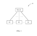
- Fig. 1 is a schematic diagram of an exemplary wireless communication system according to the present disclosure.
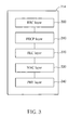
- Fig. 3 is a schematic diagram of communication protocol layers for an exemplary wireless communication system.
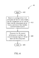
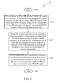
- Fig. 4 is a flowchart of an exemplary process according to the present disclosure.
- Fig. 6 is a flowchart of an exemplary process according to the present disclosure.
- Fig. 7 is a flowchart of an exemplary process according to the present disclosure.
- Fig. 1 is a schematic diagram of a wireless communication system 10 according to an example of the present disclosure.
- the wireless communication system 10 such as a long term evolution-advanced (LTE-A) system or other mobile communication systems supporting a carrier aggregation (CA) or a multiple-input multiple-output (MIMO), is briefly composed of a network and a plurality of user equipments (UEs).
- LTE-A long term evolution-advanced
- CA carrier aggregation
- MIMO multiple-input multiple-output
- the network and the UEs are simply utilized for illustrating the structure of the wireless communication system 10.
- the network can be referred as to an E-UTRAN (evolved-UTAN) comprising a plurality of evolved Node-Bs (eNBs) and relays in the LTE-A system.
- E-UTRAN evolved-UTAN
- eNBs evolved Node-Bs
- the UEs can be mobile devices such as mobile phones, laptops, tablet computers, electronic books, and portable computer systems.
- the network and the UE can be seen as a transmitter or receiver according to transmission direction, e.g., for an uplink (UL), the UE is the transmitter and the network is the receiver, and for a downlink (DL), the network is the transmitter and the UE is the receiver.
- UL uplink
- DL downlink
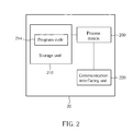
- the communication device 20 can be the UE or the network shown in Fig. 1 , but is not limited herein.
- the communication device 20 may include a processor 200 such as a microprocessor or Application Specific Integrated Circuit (ASIC), a storage unit 210 and a communication interfacing unit 220.
- the storage unit 210 may be any data storage device that can store a program code 214, accessed by the processor 200. Examples of the storage unit 210 include but are not limited to a subscriber identity module (SIM), read-only memory (ROM), flash memory, random-access memory (RAM), CD-ROM/DVD-ROM, magnetic tape, hard disk, and optical data storage device.
- SIM subscriber identity module
- ROM read-only memory
- flash memory random-access memory
- CD-ROM/DVD-ROM magnetic tape
- hard disk hard disk
- optical data storage device optical data storage device.
- the communication interfacing unit 220 is preferably a radio transceiver and can exchange wireless signals with the network according to processing results of the processor 200.
- the MAC layer 330 is responsible for a hybrid automatic repeat request (HARQ) process, multiplexing logical channels, a random access channel (RACH) procedure and maintaining a UL timing alignment.
- HARQ hybrid automatic repeat request
- RACH random access channel
- ACK acknowledgement
- NACK negative acknowledgement
- Fig. 4 is a flowchart of a process 40 according to an example of the present disclosure.
- the process 40 is utilized in a UE of the wireless communication system 10 shown in Fig. 1 , to handle UL control information.
- the process 40 may be compiled into the program code 214 and includes the following steps:
- Step 400 Start.
- the UE transmits the UL control information on the at least one control channel region of the at least one UL component carrier.
- the at least one control channel region which the UE transmits the UL control information on is sufficient to accommodate the UL control information; or, the at least one UL component carrier has bandwidth configuration sufficient to accommodate the at least one control channel region for transmitting the UL control information.
- the UE may transmit the UL control information on the at least one control channel region of a first UL component carrier of the at least one UL component carrier if an amount of the at least one UL component carrier is greater than one, wherein an amount of the at least one control channel region of the first UL component carrier is the most or sufficient for transmitting the UL control information.
- an amount of the UL control information an amount of the at least one control channel region may be greater than one.
- multiple control channel regions of multiple UL component carriers or a control channel region of a component carrier with the largest or sufficient bandwidth is used to transmit a large amount of the UL control information caused by the CA.
- multiple PUCCH signals on a UL component carrier may require multiple PUCCH regions due to the CA.
- the network may configure (or the UE may choose) a UL component carrier with a wider component carrier bandwidth (e.g. more PUCCH regions) so that it allows more flexibility to simultaneously accommodate more UL control information (e.g. more feedbacks/reports for more DL component carriers or more scheduling requests) in the PUCCH signals for the CA.
- the network may be restricted to configure the UL component carrier with at least a certain bandwidth (e.g.
- Fig. 5 is a flowchart of a process 50 according to an example of the present disclosure.
- the process 50 is utilized in a UE of the wireless communication system 10 shown in Fig. 1 , to handle a UL control channel.
- the process 50 may be compiled into the program code 214 and includes the following steps:
- the UE can perform the PUCCH transmission on the unused resource block of each of the two RB-pairs according to a network indication, a dynamic scheduling (e.g. a DL assignment index (DAI) or an acknowledgement resource index (ARI)) or a UE-specific configuration (e.g. a RRC signaling, a broadcast signaling or a UE-dedicated signaling).
- the unused resource block used for the PUCCH region may be a PUCCH format 1, a PUCCH format 1a, a PUCCH format 1b or a new PUCCH format.
- resource blocks of a PUCCH region which are not used due to an odd number of resource blocks of the PUCCH region can be exploited for the PUCCH transmission to transmit additional UL control information caused by the CA.
- an inner PUCCH region of odd number of PUCCH regions is usually reserved for a PUCCH format 1/1a/1b transmission (e.g. an ACK/NACK and/or a scheduling request)
- the unused RBs should be used (e.g. for PUCCH transmission to provide additional information code point), when multiple PUCCH regions are required for PUCCH transmissions for the CA.
- at least multiple PUCCH transmissions with larger power are allocated away from band edges to limit the interference generated by hopping to other component carriers or other frequency bands. Therefore, the UE can use the UL control channel efficiently on at least one UL component carrier according to the above illustration and the process 50, when the UE is configured with the CA.
- Fig. 6 is a flowchart of a process 60 according to an example of the present disclosure.
- the process 60 is utilized in a UE of the wireless communication system 10 shown in Fig. 1 , to handle UL control information transmission.
- the process 60 may be compiled into the program code 214 and includes the following steps:
- Step 600 Start.
- Step 610 Receive at least one component carrier-specific configuration corresponding respectively to the at least one UL component carrier, wherein each of the at least one component carrier-specific configuration comprises at least one of a sequence, a sequence hopping, a sequence group planning, a sequence group hopping, a sequence group shifting, a cyclic time shift and a cyclic time shift hopping.
- Step 620 Transmitting at least one of a PUCCH, a PUSCH and a sounding reference signal (SRS) to a network of the wireless communication system on the at least one UL component carrier according to the at least one component carrier-specific configuration.
- SRS sounding reference signal
- Step 630 End.
- the UE receives the at least one component carrier-specific configuration corresponding to the at least one UL component carrier, wherein the each of the at least one component carrier-specific configuration comprises at least one of the sequence, the sequence hopping (e.g. for resource allocation size equal to or larger than 6 resource blocks or less than 6 resource blocks with different numbers of base sequence), the sequence group planning (e.g. for each component carrier in a Hetnet deployment, inter/intra cell interference mitigation requirement is different due to various cell deployments with different operating component carriers), the sequence group hopping/shifting (e.g.
- the UE transmits the at least one of the PUCCH (e.g. a demodulation reference symbol (DM RS), a channel state information reference symbol (CSI RS) and data symbols), the PUSCH (e.g. the DM RS, the CSI RS and data symbols) and the SRS to the network of the wireless communication system on the at least one UL component carrier according to the at least one component carrier-specific configuration.
- the PUCCH e.g. a demodulation reference symbol (DM RS), a channel state information reference symbol (CSI RS) and data symbols
- the PUSCH e.g. the DM RS, the CSI RS and data symbols
- the SRS to the network of the wireless communication system on the at least one UL component carrier according to the at least one component carrier-specific configuration.
- Each of the at least one component carrier-specific configuration can be mutually independent to increase a flexibility of resource allocation for the UL control information, wherein the UE receives the each of the at least one component carrier-specific configuration independently or receives a configuration comprising the each of the at least one component carrier-specific configuration.
- an orthogonality of each difference resource is exploited to multiplex a large amount of the UL control information such that the large amount of the UL control information caused by the CA can be transmitted efficiently.
- each of the at least one component carrier-specific configuration is included in at least one of a cell broadcast signaling and a UE-specific signaling transmitted by the network, and may be derived from a common configuration by using a component carrier offset or a component carrier index. Therefore, the UE can multiplex and transmit the UL control information on at least one UL component carrier according to the above illustration and the process 60, when the UE is configured with the CA.
- Fig. 7 is a flowchart of a process 70 according to an example of the present disclosure.
- the process 70 is utilized in a UE of the wireless communication system 10 shown in Fig. 1 , to handle UL control information transmission.
- the process 70 may be compiled into the program code 214 and includes the following steps:
- Step 700 Start.
- Step 710 Receive at least one antenna-specific configuration corresponding respectively to the at least one antenna, wherein each of the at least one antenna-specific configuration comprises at least one of a orthogonal cover code, a sequence, a sequence hopping, a sequence group planning, a sequence group hopping, a sequence group shifting, a cyclic time shift and a cyclic time shift hopping.
- Step 720 Transmit at least one of a physical UL control channel (PUCCH), a physical UL shared channel (PUSCH) and a sounding reference signal (SRS) to a network of the wireless communication system via the at least one antenna according to the at least one antenna-specific configuration.
- PUCCH physical UL control channel
- PUSCH physical UL shared channel
- SRS sounding reference signal
- a UE in the LTE system can only perform the transmissions and receptions on a UL component carrier and a DL component carrier, respectively. Therefore, resources of UL control channels are sufficient for a UL control information transmission regarding feedbacks to the receptions on the DL component carrier or other control information.
- the UE in the LTE-A system can perform the transmissions and the receptions on multiple UL component carriers and multiple DL component carriers, respectively.
- the resources of the UL control channels are not sufficient for the UL control information transmission due to a large amount of the feedbacks to the receptions on the multiple DL component carriers and the other control information.
Landscapes
- Engineering & Computer Science (AREA)
- Signal Processing (AREA)
- Computer Networks & Wireless Communication (AREA)
- Mobile Radio Communication Systems (AREA)
Abstract
Description
- The present invention relates to a method used in a wireless communication system and related communication device, and more particularly, to a method of handling an uplink control channel in a wireless communication system and related communication device.
- A long-term evolution (LTE) system, initiated by the third generation partnership project (3GPP), is now being regarded as a new radio interface and radio network architecture that provides a high data rate, low latency, packet optimization, and improved system capacity and coverage. In the LTE system, a radio access network known as an evolved universal terrestrial radio access network (E-UTRAN) includes a plurality of evolved Node-Bs (eNBs) for communicating with a plurality of user equipments (UEs) and communicates with a core network including a mobility management entity (MME), serving gateway, etc for NAS (Non Access Stratum) control.
- UL control information in the LTE system includes an acknowledgement/negative acknowledgement (ACK/NACK) for downlink (DL) data, a channel quality indicator (CQI), a scheduling request (SR) and multiple-input multiple-output (MIMO) parameters (e.g. a precoding matrix indicator (PMI) and a rank indicator (RI)) of the UE. The UL control information may not be transmitted along with the data in the LTE system, i.e., transmitted by using a dedicated resource. In this situation, the UE transmits the UL control information to the eNB on a physical uplink control channel (PUCCH) in the LTE system. Resource blocks allocated to the PUCCH in a subframe, i.e., a PUCCH region, locate on edges of a system bandwidth for a low out of band (OOB) emission and a low constraint on the UL data scheduling. Besides, the resource blocks hop within slots (intra-subframe hopping) or between slots (inter-subframe hopping) for gaining frequency diversity. Moreover, UL control information of a plurality of UEs can be multiplexed in the PUCCH region by using a base sequence with different cyclic time shifts in a frequency domain, and different orthogonal block spreading codes in a time domain, so as to exploit the PUCCH region efficiently. On the other hand, a sounding reference signal (SRS) and the PUCCH cannot be transmitted in the same subframe in the LTE system. If the SRS and the PUCCH are scheduled to be transmitted in the same subframe, the UE drops the SRS or shortens the PUCCH before the transmission.
- On the other hand, the UE may also transmit the UL control information along with data when the dedicated resource is not available. In this situation, the UE first multiplexes the UL control information and the data, and then transmits the multiplexed result to the eNB on a physical uplink shared channel (PUSCH) in the LTE system. Please note that, the UE can only select the one of the PUCCH and the PUSCH to transmit the UL control information but not both so as to maintain a single carrier property. Besides, the CQI is transmitted periodically by the UE when using the PUCCH, but is transmitted aperiodically, i.e., triggered by a request from the eNB, when using the PUSCH.
- A long term evolution-advanced (LTE-A) system, as its name implies, is an evolution of the LTE system. The LTE-A system targets faster switching between power states, improves performance at the coverage edge of the eNB, and includes subjects, such as bandwidth extension, coordinated multipoint transmission/reception (CoMP), UL multiple-input multiple-output (MIMO), etc.
- For bandwidth extension, a carrier aggregation (CA) is introduced to the LTE-A system by which two or more component carriers are aggregated to achieve a wider-band transmission. Accordingly, the LTE-A system can support a wider bandwidth up to 100MHz by aggregating a maximum number of 5 component carriers, where bandwidth of each component carrier is 20MHz and is backward compatible with 3GPP Rel-8. An LTE-A specification supports CA for both continuous and non-continuous component carriers with each component carrier limited to a maximum of 110 resource blocks. The CA increases bandwidth flexibility by aggregating the non-continuous component carriers. A component carrier is either used as a UL component carrier or a downlink (DL) component carrier, but not both. Further, there is a one-to-one correspondence between the UL component carrier and the DL component carrier, i.e., each UL component carrier is paired with a corresponding DL component carrier.
- When the UE is configured with the CA, the UE is allowed to receive and transmit data on one or multiple component carriers to increase the data rate. In the LTE-A system, it is possible for the eNB to configure the UE different numbers of UL and DL component carriers which depend on UL and DL aggregation capabilities, respectively. Moreover, the component carriers configured to the UE necessarily consists of one DL primary component carrier (PCC) and one UL primary component carrier. Component carriers other than the primary component carriers are named UL or DL secondary component carriers (SCCs). The numbers of UL and DL secondary component carriers are arbitrary, and are related to the UE capability and available radio resource. The UL and DL primary component carriers are used for establishing and re-establishing the radio resource control (RRC), and transmitting and receiving the system information. The UL or DL primary component carrier can not be de-activated, but can be changed by a handover procedure with the RACH procedure.
- The UL MIMO (e.g. UL single user-MIMO, UL SU-MIMO) technique is used to achieve higher data rates, higher spectrum efficiency and improved system capacity by enabling parallel data streams to be exchanged between the eNB and the UE. In general, the UL MIMO technique should be implemented by using multiple transmitting and receiving antennas at both the UE and the eNB. However, even though the eNB can be equipped with the multiple transmitting and receiving antennas, most of the UEs are equipped with only one transmitting antenna and one receiving antenna due to a limited size. The advantage of the UL MIMO technique is thus limited. The UL multiuser MIMO (MU-MIMO) technique is used in the LTE-A system to solve this problem. With the UL MU-MIMO technique, the eNB schedules the UEs each with a transmitting antenna to transmit on the same frequency band by multiplexing data of the UEs. Advantages such as higher data rates, higher spectrum efficiency and improved system capacity can be realized.
- Since the UL control channel including both the PUCCH and the PUSCH in the LTE system is designed for the UE and the network with only a single component carrier and without the MIMO, the method cannot be directly applied to the LTE-A system with the CA and the MIMO. In detail, additional UL control information for the CA and the MIMO is needed to be transmitted on the UL control channel, and the UL control channel in the LTE system can not accommodate the additional UL control information without multiplexing the UL control information or extending the UL control channel. Therefore, how to utilize or extended the UL control channel in the LTE system to adapt to the CA and the MIMO is a topic for discussion. Accordingly, parameters and protocols as well as respective signalings related to the PUCCH and the PUSCH in the LTE system must be extended or modified for the LTE-A system.
- When carrier aggregation is not well considered in the LTE system, inefficient use of PUCCH rises and there are several problems required to be solved. First, it is known that system bandwidths of 1.4, 3, 5, 10 and 20MHz are normally configured with 1, 2, 4, 8 and 16 PUCCH regions, respectively. However, it is not clear how multiple PUCCH signals are transmitted on multiple PUCCH under carrier aggregation, according to the prior art. Second, for the case of an odd number of PUCCH regions, one resource block (RB) of an RB-pair in each slot is not used for the PUCCH, which wastes uplink resources. Besides, due to the CA, a high rank UL SU-MIMO and a UL MU-MIMO techniques (e.g. especially in a HetNet deployment), it is not clear how interference mitigation is realized for a transmission of reference signal and data. Even though the transmission of reference signal and data on different component carriers do not interfere with each other by using a frequency division multiplexing (FDM), with UEs operating with the high rank UL SU-MIMO or the UL MU-MIMO on the same component carrier or even the same resource blocks, reference signal and data could interfere to its own, respectively.
- The disclosure therefore provides a method and related communication device for handling UL control information and a UL control channel to solve the abovementioned problems.
- A method of handling uplink (UL) control information for a mobile device supporting a carrier aggregation (CA) in a wireless communication system is disclosed. The method comprises receiving a configuration or an activation of the CA with at least one UL component carrier and at least one downlink (DL) component carrier from a network of the wireless communication system, and transmitting the UL control information on at least one control channel region of the at least one UL component carrier; wherein the at least one UL component carrier has a bandwidth configuration sufficient to accommodate the at least one control channel region for transmitting the UL control information.
- A method of handling an uplink (UL) control channel for a mobile device supporting a carrier aggregation (CA) with at least one downlink (DL) component carrier and at least one UL component carrier in a wireless communication system is disclosed. The method comprises being configured with an odd number of PUCCH regions by a network of the wireless communication system, wherein the last odd-numbered PUCCH region or the most inner PUCCH region relates to two subcarriers of two RB pairs with an unused resource block (RB) of each of the two RB pairs in each slot, obtaining UL control information corresponding to at least one UL transmission on the at least one UL component carrier, or at least one DL signaling or at least one DL transmission on the at least one DL component carrier, wherein a plurality of PUCCH resources or regions are required to accommodate the obtained UL control information, and performing a PUCCH transmission to provide the UL control information on at least one of the unused resource block of each of the two RB pairs and the last odd-numbered PUCCH region or the most inner PUCCH region.
- A method of handling uplink (UL) control information transmission, UL data transmission and UL signaling for a mobile device supporting a carrier aggregation (CA) with at least one UL component carrier in a wireless communication system is disclosed. The method comprises receiving at least one component carrier-specific configuration corresponding respectively to the at least one UL component carrier, wherein each of the at least one component carrier-specific configuration comprises at least one of a sequence, a sequence hopping, a sequence group planning, a sequence group hopping, a sequence group shifting, a cyclic time shift and a cyclic time shift hopping, and transmitting at least one of a physical UL control channel (PUCCH), a physical UL shared channel (PUSCH) and a sounding reference signal (SRS) to a network of the wireless communication system on the at least one UL component carrier according to the at least one component carrier-specific configuration.
- A method of handling uplink (UL) control information transmission, UL data transmission and UL signaling for a mobile device supporting a multiple-input multiple-output (MIMO) with at least one antenna in a wireless communication system is disclosed. The method comprises receiving at least one antenna-specific configuration corresponding respectively to the at least one antenna, wherein each of the at least one antenna-specific configuration comprises at least one of a orthogonal cover code, a sequence, a sequence hopping, a sequence group planning, a sequence group hopping, a sequence group shifting, a cyclic time shift and a cyclic time shift hopping, and transmitting at least one of a physical UL control channel (PUCCH), a physical UL shared channel (PUSCH) and a sounding reference signal (SRS) to a network of the wireless communication system via the at least one antenna according to the at least one antenna-specific configuration.
- These and other objectives of the present invention will no doubt become obvious to those of ordinary skill in the art after reading the following detailed description of the preferred embodiment that is illustrated in the various figures and drawings.
-
Fig. 1 is a schematic diagram of an exemplary wireless communication system according to the present disclosure. -
Fig. 2 is a schematic diagram of an exemplary communication device according to the present disclosure. -
Fig. 3 is a schematic diagram of communication protocol layers for an exemplary wireless communication system. -
Fig. 4 is a flowchart of an exemplary process according to the present disclosure. -
Fig. 5 is a flowchart of an exemplary process according to the present disclosure. -
Fig. 6 is a flowchart of an exemplary process according to the present disclosure. -
Fig. 7 is a flowchart of an exemplary process according to the present disclosure. - Please refer to
Fig. 1 , which is a schematic diagram of awireless communication system 10 according to an example of the present disclosure. Thewireless communication system 10, such as a long term evolution-advanced (LTE-A) system or other mobile communication systems supporting a carrier aggregation (CA) or a multiple-input multiple-output (MIMO), is briefly composed of a network and a plurality of user equipments (UEs). InFig. 1 , the network and the UEs are simply utilized for illustrating the structure of thewireless communication system 10. Practically, the network can be referred as to an E-UTRAN (evolved-UTAN) comprising a plurality of evolved Node-Bs (eNBs) and relays in the LTE-A system. The UEs can be mobile devices such as mobile phones, laptops, tablet computers, electronic books, and portable computer systems. Besides, the network and the UE can be seen as a transmitter or receiver according to transmission direction, e.g., for an uplink (UL), the UE is the transmitter and the network is the receiver, and for a downlink (DL), the network is the transmitter and the UE is the receiver. - Please refer to
Fig. 2 , which is a schematic diagram of acommunication device 20 according to an example of the present disclosure. Thecommunication device 20 can be the UE or the network shown inFig. 1 , but is not limited herein. Thecommunication device 20 may include aprocessor 200 such as a microprocessor or Application Specific Integrated Circuit (ASIC), astorage unit 210 and acommunication interfacing unit 220. Thestorage unit 210 may be any data storage device that can store aprogram code 214, accessed by theprocessor 200. Examples of thestorage unit 210 include but are not limited to a subscriber identity module (SIM), read-only memory (ROM), flash memory, random-access memory (RAM), CD-ROM/DVD-ROM, magnetic tape, hard disk, and optical data storage device. Thecommunication interfacing unit 220 is preferably a radio transceiver and can exchange wireless signals with the network according to processing results of theprocessor 200. - Please refer to
Fig. 3 , which illustrates a schematic diagram of communication protocol layers for the LTE-Advanced system. The behaviors of some of the protocol layers may be defined in theprogram code 214 and executed by the processing means 200. The protocol layers from top to bottom are a radio resource control (RRC)layer 300, a packet data convergence protocol (PDCP)layer 310, a radio link control (RLC)layer 320, a medium access control (MAC)layer 330 and a physical (PHY)layer 340. TheRRC layer 300 is used for performing broadcast, paging, RRC connection management, measurement reporting and control, and radio bearer control responsible for generating or releasing radio bearers. ThePHY layer 340 is used to provide physical channels, e.g. a physical UL control channel (PUCCH) and a physical UL shared channel (PUSCH), such that UL control information and data of different UEs can be transmitted and received with low interferences or even without the interferences. TheMAC layer 330 is responsible for a hybrid automatic repeat request (HARQ) process, multiplexing logical channels, a random access channel (RACH) procedure and maintaining a UL timing alignment. In each HARQ process, an acknowledgement (ACK) is reported to the network if the MAC data/control packet is received and decoded successfully. Otherwise, an HARQ negative acknowledgement (NACK) is reported to the network. - Please refer to
Fig. 4 , which is a flowchart of aprocess 40 according to an example of the present disclosure. Theprocess 40 is utilized in a UE of thewireless communication system 10 shown inFig. 1 , to handle UL control information. Theprocess 40 may be compiled into theprogram code 214 and includes the following steps: - Step 400: Start.
- Step 410: Receive a configuration or an activation of the CA with at least one UL component carrier and at least one DL component carrier from a network of the wireless communication system.
- Step 420: Transmit the UL control information on at least one control channel region of the at least one UL component carrier.
- Step 430: End.
- According to the
process 40, after the UE receives the configuration or the activation (or the UE is already configured) of the CA with the at least one UL component carrier and the at least one DL component carrier from the network of the wireless communication system, the UE transmits the UL control information on the at least one control channel region of the at least one UL component carrier. Note that, the at least one control channel region which the UE transmits the UL control information on is sufficient to accommodate the UL control information; or, the at least one UL component carrier has bandwidth configuration sufficient to accommodate the at least one control channel region for transmitting the UL control information. Further, the UE may transmit the UL control information on the at least one control channel region of a first UL component carrier of the at least one UL component carrier if an amount of the at least one UL component carrier is greater than one, wherein an amount of the at least one control channel region of the first UL component carrier is the most or sufficient for transmitting the UL control information. According to an amount of the UL control information, an amount of the at least one control channel region may be greater than one. In short, multiple control channel regions of multiple UL component carriers or a control channel region of a component carrier with the largest or sufficient bandwidth is used to transmit a large amount of the UL control information caused by the CA. - On the other hand, availability information of the at least one control channel region for the UE is included in at least one of a cell-specific signaling, a UE-specific signaling and a CA configuration signaling transmitted by the network, such that the UE can choose the at least one control channel region for transmitting the UL control information. Furthermore, the at least one of the cell-specific signaling, the UE-specific signaling and the CA configuration signaling comprises at least one of a control channel region resource index and an amount of the at least one control channel region for each possible control channel format or for part of control channel formats. Accordingly, the UE can transmit the UL control information when the UE needs to response at least one transmission on the at least one DL component carrier, or the UE needs to transmit a scheduling request (SR) for further data transmission on the at least one UL component carrier. To obtain the at least one control channel region, the UE can use the control channel region resource index included in the at least one of the cell-specific signaling, the UE-specific signaling and the CA configuration signaling transmitted by the network. Alternatively, the UE can derive the at least one control channel region by using a configured parameter (e.g. according to a location of a specific PDCCH control channel element (CCE)), wherein if the control channel region resource index is used for the at least one control channel region, the control channel region resource index is explicitly signaled to the UE or is derived by the UE by using a received parameter. Besides, to reduce an amount of the control channel region resource index or to reduce a complexity of transmitting the UL control information, an amount of the at least one control channel region of each of the at least one UL component carrier can be fixed or the same.
- In short, according to possible transmission schemes (e.g. a feedback multiplexing or a bundling) for the UL control channel, multiple PUCCH signals on a UL component carrier may require multiple PUCCH regions due to the CA. In such a situation, the network may configure (or the UE may choose) a UL component carrier with a wider component carrier bandwidth (e.g. more PUCCH regions) so that it allows more flexibility to simultaneously accommodate more UL control information (e.g. more feedbacks/reports for more DL component carriers or more scheduling requests) in the PUCCH signals for the CA. Alternatively, the network may be restricted to configure the UL component carrier with at least a certain bandwidth (e.g. for possible concurrent at most 5 PUCCH regions because of 5 DL component carriers and 1 UL component carrier). Or, at least one UL component carrier should have enough PUCCH regions to accommodate all feedbacks/reports for DL component carriers and scheduling requests. Therefore, the UL control information can be transmitted successfully on the at least one UL component carrier according to the above illustration and the
process 40, when the UE is configured with the CA. - Please refer to
Fig. 5 , which is a flowchart of aprocess 50 according to an example of the present disclosure. Theprocess 50 is utilized in a UE of thewireless communication system 10 shown inFig. 1 , to handle a UL control channel. Theprocess 50 may be compiled into theprogram code 214 and includes the following steps: - Step 500: Start.
- Step 510: Be configured with an odd number of PUCCH regions by a network of the wireless communication system, wherein the last odd-numbered PUCCH region or the most inner PUCCH region relates to two subcarriers of two RB pairs with an unused resource block (RB) of each of the two RB pairs in each slot.
- Step 520: Obtain UL control information corresponding to at least one UL transmission on at least one UL component carrier, or at least one DL signaling or at least one DL transmission on at least one DL component carrier, wherein a plurality of PUCCH resources or regions are required to accommodate the obtained UL control information.
- Step 530: Performing a PUCCH transmission to provide the UL control information on at least one of the unused resource block of each of the two RB pairs and the last odd-numbered PUCCH region or the most inner PUCCH region.
- Step 540: End.
- According to the
process 50, for the UE supporting a CA with the at least one DL component carrier and the at least one DL component carrier in the wireless communication system, the UE is configured with the odd number of PUCCH regions by the network of the wireless communication system, wherein the last odd-numbered PUCCH region or the most inner PUCCH region relates to two subcarriers of two RB pairs with the unused resource block (RB) of the each of the two RB pairs in each slot. Then, the UE obtains the UL control information (e.g. a CQI, a precoding matrix indicator (PMI), the rank indicator (RI), the scheduling request, or an ACK/NACK) corresponding to the at least one UL transmission on the at least one UL component carrier, or the at least one DL signaling or the at least one DL transmission on the at least one DL component carrier, wherein the plurality of PUCCH resources or regions are required to accommodate the obtained UL control information. After that, the UE performs the PUCCH transmission to provide the UL control information on the at least one of the unused resource block of each of the two RB pairs and the last odd-numbered PUCCH region or the most inner PUCCH region. Further, the UE can perform the PUCCH transmission on the unused resource block of each of the two RB-pairs according to a network indication, a dynamic scheduling (e.g. a DL assignment index (DAI) or an acknowledgement resource index (ARI)) or a UE-specific configuration (e.g. a RRC signaling, a broadcast signaling or a UE-dedicated signaling). The unused resource block used for the PUCCH region may be a PUCCH format 1, a PUCCH format 1a, a PUCCH format 1b or a new PUCCH format. In short, resource blocks of a PUCCH region which are not used due to an odd number of resource blocks of the PUCCH region can be exploited for the PUCCH transmission to transmit additional UL control information caused by the CA. - In short, in order to exploit unused resource blocks in each slot in the case of an odd number of PUCCH regions, the eNB may schedule the UE to perform an intra subframe frequency hopping (i.e. a mirror hopping) for PUSCH allocation in the unused Resource blocks. Alternatively, the UE can be assigned a localized allocation which includes unused RB-pair. In this case, the UE will transmit PUSCH data on both resource blocks of the unused RB-pair, assuming that neither of the resource blocks is used for the PUCCH by any UE in the subframe. Thus, the eNB can appropriately schedule the PUSCH transmission (mirror hopping or localized) on the PUCCH resource blocks when they are under-utilized. On the other hand, since an inner PUCCH region of odd number of PUCCH regions is usually reserved for a PUCCH format 1/1a/1b transmission (e.g. an ACK/NACK and/or a scheduling request), the unused RBs should be used (e.g. for PUCCH transmission to provide additional information code point), when multiple PUCCH regions are required for PUCCH transmissions for the CA. Please note that, at least multiple PUCCH transmissions with larger power are allocated away from band edges to limit the interference generated by hopping to other component carriers or other frequency bands. Therefore, the UE can use the UL control channel efficiently on at least one UL component carrier according to the above illustration and the
process 50, when the UE is configured with the CA. - Please refer to
Fig. 6 , which is a flowchart of aprocess 60 according to an example of the present disclosure. Theprocess 60 is utilized in a UE of thewireless communication system 10 shown inFig. 1 , to handle UL control information transmission. Theprocess 60 may be compiled into theprogram code 214 and includes the following steps: - Step 600: Start.
- Step 610: Receive at least one component carrier-specific configuration corresponding respectively to the at least one UL component carrier, wherein each of the at least one component carrier-specific configuration comprises at least one of a sequence, a sequence hopping, a sequence group planning, a sequence group hopping, a sequence group shifting, a cyclic time shift and a cyclic time shift hopping.
- Step 620: Transmitting at least one of a PUCCH, a PUSCH and a sounding reference signal (SRS) to a network of the wireless communication system on the at least one UL component carrier according to the at least one component carrier-specific configuration.
- Step 630: End.
- According to the
process 60, for the UE supporting a CA with the at least one UL component carrier in the wireless communication system, the UE receives the at least one component carrier-specific configuration corresponding to the at least one UL component carrier, wherein the each of the at least one component carrier-specific configuration comprises at least one of the sequence, the sequence hopping (e.g. for resource allocation size equal to or larger than 6 resource blocks or less than 6 resource blocks with different numbers of base sequence), the sequence group planning (e.g. for each component carrier in a Hetnet deployment, inter/intra cell interference mitigation requirement is different due to various cell deployments with different operating component carriers), the sequence group hopping/shifting (e.g. including a hopping pattern, a shift offset, a sequence group assignment and/or a PUCCH resource index assignment), the cyclic time shift and the cyclic time shift hopping. Then, the UE transmits the at least one of the PUCCH (e.g. a demodulation reference symbol (DM RS), a channel state information reference symbol (CSI RS) and data symbols), the PUSCH (e.g. the DM RS, the CSI RS and data symbols) and the SRS to the network of the wireless communication system on the at least one UL component carrier according to the at least one component carrier-specific configuration. Each of the at least one component carrier-specific configuration can be mutually independent to increase a flexibility of resource allocation for the UL control information, wherein the UE receives the each of the at least one component carrier-specific configuration independently or receives a configuration comprising the each of the at least one component carrier-specific configuration. In short, an orthogonality of each difference resource is exploited to multiplex a large amount of the UL control information such that the large amount of the UL control information caused by the CA can be transmitted efficiently. - For flexibly multiplexing the UL control information corresponding to different component carriers or different UEs, numbers of base sequences and/or base sequence corresponding to the at least one UL component carrier may be different, all the same or partly the same. Alternatively, numbers of cyclic time shifts and/or cyclic time shifts corresponding to the at least one UL component carrier may be different, all the same or partly the same. Besides, each of the at least one component carrier-specific configuration is included in at least one of a cell broadcast signaling and a UE-specific signaling transmitted by the network, and may be derived from a common configuration by using a component carrier offset or a component carrier index. Therefore, the UE can multiplex and transmit the UL control information on at least one UL component carrier according to the above illustration and the
process 60, when the UE is configured with the CA. - Please refer to
Fig. 7 , which is a flowchart of aprocess 70 according to an example of the present disclosure. Theprocess 70 is utilized in a UE of thewireless communication system 10 shown inFig. 1 , to handle UL control information transmission. Theprocess 70 may be compiled into theprogram code 214 and includes the following steps: - Step 700: Start.
- Step 710: Receive at least one antenna-specific configuration corresponding respectively to the at least one antenna, wherein each of the at least one antenna-specific configuration comprises at least one of a orthogonal cover code, a sequence, a sequence hopping, a sequence group planning, a sequence group hopping, a sequence group shifting, a cyclic time shift and a cyclic time shift hopping.
- Step 720: Transmit at least one of a physical UL control channel (PUCCH), a physical UL shared channel (PUSCH) and a sounding reference signal (SRS) to a network of the wireless communication system via the at least one antenna according to the at least one antenna-specific configuration.
- Step 730: End.
- According to the
process 70, for the UE supporting a MIMO with the at least one antenna in the wireless communication system, the UE receives the at least one antenna-specific configuration corresponding to the at least one antenna, wherein each of the at least one antenna-specific configuration comprises at least one of the orthogonal cover code (e.g. for spreading), the sequence, the sequence hopping (e.g. for resource allocation size equal to or larger than 6 resource blocks or less than 6 resource blocks with different numbers of base sequence), the sequence group planning, the sequence group hopping/shifting (e.g. including a hopping pattern, a shift offset, a sequence group assignment and/or a PUCCH resource index assignment), the cyclic time shift and the cyclic time shift hopping. Then, the UE transmits the at least one of the PUCCH (e.g. a DM RS, a CSI RS and data symbols), the PUSCH (e.g. the DM RS, CSI RS and data symbols) and the SRS to the network of the wireless communication system via the at least one antenna according to the at least one antenna-specific configuration. According to the UE capability and a deployment of the network, the MIMO can be a single-user MIMO (SU-MIMO) or a multi-user (MU-MIMO). Each of the at least one antenna-specific configuration can be mutually independent increase a flexibility of resource allocation for the UL control information, wherein the UE receives each of the at least one antenna-specific configuration independently or receives a configuration comprising each of the at least one antenna-specific configuration. In short, an orthogonality of each difference resource is exploited to multiplex a large amount of the UL control information such that the large amount of the UL control information caused by the MIMO can be transmitted efficiently. - For multiplexing the UL control information corresponding to the MIMO or different UEs, numbers of base sequences and/or bases sequences corresponding to the at least one antenna may be different, all the same or partly the same. Alternatively, numbers of cyclic time shifts and/or cyclic time shifts corresponding to the at least one antenna may be different, all the same or partly the same. Or, numbers of orthogonal cover codes and/or orthogonal cover codes corresponding to the at least one antenna may be different, all the same or partly the same. Besides, each of the at least one antenna-specific configuration is included in at least one of a cell broadcast signaling and a UE-specific signaling, and may be configured by using an antenna offset or an antenna index. Further, the orthogonal cover code is used when at least one of the sequence hopping and the sequence group hopping is disabled so as to maintain an orthogonality between the UL control information corresponding to different antennas or different UEs. In addition, the UE may perform at least one of the sequence hopping and the sequence group hopping at a subframe level or a slot level. The UE may perform the cyclic time shift hopping at a subframe level or a slot level, or may disable the cyclic time shift hopping. The UE may derive each of the at least one antenna-specific configuration from a common configuration by using an antenna offset or an antenna index.
- Please note that, abovementioned illustrations are both applicable to the UE using one or multiple physical antennas and the UE using one or multiple antenna ports (virtual antennas) identified by respective (orthogonal) reference signals, i.e., each term "antenna" is replaced by the term "antenna port".
- In short, when different component carriers suffer from different delay spreads, the required number of cyclic time shifts may also be different for interference mitigation among different number of UEs (even for a similar amount of UE) . In addition, bandwidth for each component carrier could vary according to different sizes of allocated resources which also affect possible sequence lengths and possible cyclic time shifts necessary. Therefore, the UE can multiplex and transmit the UL control information via the at least one antenna without interference to its own according to the above illustration and the
process 70, when the UE is configured with the MIMO. - Besides, the abovementioned steps of the processes including suggested steps can be realized by means that could be a hardware, a firmware known as a combination of a hardware device and computer instructions and data that reside as read-only software on the hardware device, or an electronic system. Examples of hardware can include analog, digital and mixed circuits known as microcircuit, microchip, or silicon chip. Examples of the electronic system can include a system on chip (SOC), system in package (SiP), a computer on module (COM), and the
communication device 20. - In conclusion, a UE in the LTE system can only perform the transmissions and receptions on a UL component carrier and a DL component carrier, respectively. Therefore, resources of UL control channels are sufficient for a UL control information transmission regarding feedbacks to the receptions on the DL component carrier or other control information. However, the UE in the LTE-A system can perform the transmissions and the receptions on multiple UL component carriers and multiple DL component carriers, respectively. The resources of the UL control channels are not sufficient for the UL control information transmission due to a large amount of the feedbacks to the receptions on the multiple DL component carriers and the other control information. On the other hand, the UE causes interference to its own when using a high rank UL SU-MIMO or a UL MU-MIMO on the same component carrier or the same resource blocks. Therefore, additional resources must be used for the increased UL control information or the UL control information must be multiplexed for an efficient use of limited resources. The exemplary method and means are provided accordingly to enhance the UL control information transmission for the UE in the LTE system to operate in the wireless communication system (e.g. the LTE-A system) with the CA or the MIMO.
- Those skilled in the art will readily observe that numerous modifications and alterations of the device and method may be made while retaining the teachings of the invention. Accordingly, the above disclosure should be construed as limited only by the metes and bounds of the appended claims.
Claims (22)
- A method of handling uplink (UL) control information for a mobile device supporting a carrier aggregation (CA) in a wireless communication system, the method comprising:receiving a configuration or an activation of the CA with at least one UL component carrier and at least one downlink (DL) component carrier from a network of the wireless communication system; andtransmitting the UL control information on at least one control channel region of the at least one UL component carrier;wherein the at least one UL component carrier has a bandwidth configuration sufficient to accommodate the at least one control channel region for transmitting the UL control information.
- The method of claim 1, wherein transmitting the UL control information on the at least one control channel region of the at least one UL component carrier comprises:transmitting the UL control information on at least one control channel region of a first UL component carrier of the at least one UL component carrier if an amount of the at least one UL component carrier is greater than one, wherein an amount of the at least one control channel region of the first UL component carrier is the most or sufficient for transmitting the UL control information.
- The method of claim 1, wherein an amount of the at least one control channel region is greater than one, and availability information of the at least one control channel region for the mobile device is comprised in at least one of a cell-specific signaling, a mobile device-specific signaling and a CA configuration signaling.
- The method of claim 3, wherein the at least one of the cell-specific signaling, the mobile device-specific signaling and the CA configuration signaling comprises at least one of a control channel region resource index and an amount of the at least one control channel region for each possible control channel format or for part of control channel formats.
- The method of claim 1, wherein the UL control information relates to at least one transmission on the at least one DL component carrier or relates to a scheduling request.
- The method of claim 1, wherein the at least one control channel region is explicitly signaled to the mobile device, or is indicated by using a control channel region resource index, or is implicitly derived by the mobile device by using a configured parameter; and when the control channel region resource index is used for the at least one control channel region, the control channel region resource index is explicitly signaled to the mobile device or is derived by the mobile device by using a received parameter, and an amount of the at least one control channel region of each of the at least one uplink component carrier is fixed or the same.
- A method of handling an uplink (UL) control channel for a mobile device supporting a carrier aggregation (CA) with at least one downlink (DL) component carrier and at least one UL component carrier in a wireless communication system, the method comprising:being configured with an odd number of PUCCH regions by a network of the wireless communication system, wherein the last odd-numbered PUCCH region or the most inner PUCCH region relates to two subcarriers of two RB pairs with an unused resource block (RB) of each of the two RB pairs in each slot;obtaining UL control information corresponding to at least one UL transmission on the at least one UL component carrier, or at least one DL signaling or at least one DL transmission on the at least one DL component carrier, wherein a plurality of PUCCH resources or regions are required to accommodate the obtained UL control information; andperforming a PUCCH transmission to provide the UL control information on at least one of the unused resource block of each of the two RB pairs and the last odd-numbered PUCCH region or the most inner PUCCH region.
- The method of claim 7 further comprising performing the PUCCH transmission on the unused resource block of each of the two RB pairs according to a network indication, a dynamic scheduling, or a mobile device-specific configuration.
- The method of claim 7, wherein the unused resource block is used for the PUCCH region of a PUCCH format 1, a PUCCH format 1a, a PUCCH format 1b or a new PUCCH format.
- A method of handling uplink (UL) control information transmission, UL data transmission and UL signaling for a mobile device supporting a carrier aggregation (CA) with at least one UL component carrier in a wireless communication system, the method comprising:receiving at least one component carrier-specific configuration corresponding respectively to the at least one UL component carrier, wherein each of the at least one component carrier-specific configuration comprises at least one of a sequence, a sequence hopping, a sequence group planning, a sequence group hopping, a sequence group shifting, a cyclic time shift and a cyclic time shift hopping; andtransmitting at least one of a physical UL control channel (PUCCH), a physical UL shared channel (PUSCH) and a sounding reference signal (SRS) to a network of the wireless communication system on the at least one UL component carrier according to the at least one component carrier-specific configuration.
- The method of claim 10, wherein each of the at least one component carrier-specific configuration is mutually independent, wherein the mobile device receives each of the at least one component carrier-specific configuration independently or receives a configuration comprising each of the at least one component carrier-specific configuration.
- The method of claim 10, wherein numbers of base sequences corresponding to the at least one UL component carrier are different, all the same or partly the same; the bases sequences corresponding to the at least one UL component carrier are different, all the same or partly the same; or both the numbers of the base sequences and the bases sequences corresponding to the at least one UL component carrier are different, all the same or partly the same; and/or numbers of cyclic time shifts corresponding to the at least one UL component carrier are different, all the same or partly the same; or the cyclic time shifts corresponding to the at least one UL component carrier are different, all the same or partly the same; or both the numbers of the cyclic time shifts and the cyclic time shifts corresponding to the at least one UL component carrier are different, all the same or partly the same.
- The method of claim 10, wherein each of the at least one component carrier-specific configuration is comprised in at least one of a cell broadcast signaling and a mobile device-specific signaling; and/or each of the at least one component carrier-specific configuration is derived from a common configuration by using a component carrier offset or a component carrier index.
- A method of handling uplink (UL) control information transmission, UL data transmission and UL signaling for a mobile device supporting a multiple-input multiple-output (MIMO) with at least one antenna in a wireless communication system, the method comprising:receiving at least one antenna-specific configuration corresponding respectively to the at least one antenna, wherein each of the at least one antenna-specific configuration comprises at least one of a orthogonal cover code, a sequence, a sequence hopping, a sequence group planning, a sequence group hopping, a sequence group shifting, a cyclic time shift and a cyclic time shift hopping; andtransmitting at least one of a physical UL control channel (PUCCH), a physical UL shared channel (PUSCH) and a sounding reference signal (SRS) to a network of the wireless communication system via the at least one antenna according to the at least one antenna-specific configuration.
- The method of claim 14, wherein the MIMO is a single-user MIMO (SU-MIMO) or a multi-user MIMO (MU-MIMO) and the antenna refers to a physical antenna or an antenna port identified by reference signal.
- The method of claim 14, wherein each of the at least one antenna-specific configuration is mutually independent, wherein the mobile device receives each of the at least one antenna-specific configuration independently or receives a configuration comprising each of the at least one antenna-specific configuration.
- The method of claim 14, wherein numbers of base sequences corresponding to the at least one antenna are different, all the same or partly the same; the bases sequences corresponding to the at least one antenna are different, all the same or partly the same; or both the numbers of base sequences and the bases sequences corresponding to the at least one antenna are different, all the same or partly the same.
- The method of claim 14, wherein numbers of cyclic time shifts corresponding to the at least one antenna are different, all the same or partly the same; cyclic time shifts corresponding to the at least one antenna are different, all the same or partly the same; or both the numbers of cyclic time shifts and the cyclic time shifts corresponding to the at least one antenna are different, all the same or partly the same; and/or
numbers of orthogonal cover codes corresponding to the at least one antenna are different, all the same or partly the same; the orthogonal cover codes corresponding to the at least one antenna are different, all the same or partly the same; or both the numbers of orthogonal cover codes and the orthogonal cover codes corresponding to the at least one antenna are different, all the same or partly the same. - The method of claim 14, wherein each of the at least one antenna-specific configuration is comprised in at least one of a cell broadcast signaling and a mobile device-specific signaling; and/or
each of the at least one antenna-specific configuration is derived from a common configuration by using an antenna offset or an antenna index. - The method of claim 14, wherein the orthogonal cover code is used when at least one of the sequence hopping and the sequence group hopping is disabled.
- The method of claim 14, wherein at least one of the sequence hopping and the sequence group hopping is performed at a subframe level or a slot level; and/or the cyclic time shift hopping is performed at a subframe level or a slot level, or is disabled.
- A communication device of a wireless communication system for performing the method of any one of the preceding claims, for handling uplink control information.
Applications Claiming Priority (1)
| Application Number | Priority Date | Filing Date | Title |
|---|---|---|---|
| US33184010P | 2010-05-06 | 2010-05-06 |
Publications (2)
| Publication Number | Publication Date |
|---|---|
| EP2385651A2 true EP2385651A2 (en) | 2011-11-09 |
| EP2385651A3 EP2385651A3 (en) | 2012-07-25 |
Family
ID=44486962
Family Applications (3)
| Application Number | Title | Priority Date | Filing Date |
|---|---|---|---|
| EP11003747A Withdrawn EP2385651A3 (en) | 2010-05-06 | 2011-05-06 | Method of handling an uplink control channel and related communication device |
| EP11003745A Withdrawn EP2385647A3 (en) | 2010-05-06 | 2011-05-06 | Method of multiplexing and transmission of uplink control information and related communication device |
| EP11003746A Withdrawn EP2385650A3 (en) | 2010-05-06 | 2011-05-06 | Method of handling a physical uplink control channel transmission and related communication device |
Family Applications After (2)
| Application Number | Title | Priority Date | Filing Date |
|---|---|---|---|
| EP11003745A Withdrawn EP2385647A3 (en) | 2010-05-06 | 2011-05-06 | Method of multiplexing and transmission of uplink control information and related communication device |
| EP11003746A Withdrawn EP2385650A3 (en) | 2010-05-06 | 2011-05-06 | Method of handling a physical uplink control channel transmission and related communication device |
Country Status (4)
| Country | Link |
|---|---|
| US (3) | US20120113910A1 (en) |
| EP (3) | EP2385651A3 (en) |
| CN (3) | CN102237963A (en) |
| TW (3) | TW201210238A (en) |
Cited By (2)
| Publication number | Priority date | Publication date | Assignee | Title |
|---|---|---|---|---|
| JP2015521452A (en) * | 2012-05-31 | 2015-07-27 | サムスン エレクトロニクス カンパニー リミテッド | Method and apparatus for transmitting / receiving physical channel in communication system supporting carrier aggregation |
| EP2936712A4 (en) * | 2012-12-21 | 2016-09-14 | Ericsson Telefon Ab L M | METHODS AND APPARATUSES FOR LIMITING INTERFERENCE BETWEEN CELLS ON A CONTROL CHANNEL |
Families Citing this family (107)
| Publication number | Priority date | Publication date | Assignee | Title |
|---|---|---|---|---|
| KR101701444B1 (en) * | 2009-10-02 | 2017-02-03 | 인터디지탈 패튼 홀딩스, 인크 | Method and apparatus for controlling transmit power of transmissions on more than one component carrier |
| KR101606803B1 (en) * | 2010-04-29 | 2016-03-28 | 엘지전자 주식회사 | A method and a base station for transmitting control information, and a method and a user equipment for receiving control information |
| US9413498B2 (en) * | 2010-05-26 | 2016-08-09 | Innovative Sonic Corporation | Method and apparatus for handling buffer status reporting in a wireless communication system |
| US9326211B2 (en) * | 2010-06-10 | 2016-04-26 | Interdigital Patent Holdings, Inc. | Reconfiguration and handover procedures for fuzzy cells |
| US9762372B2 (en) | 2010-06-15 | 2017-09-12 | Texas Instruments Incorporated | CSI reporting on PUSCH for carrier aggregation |
| WO2011162522A2 (en) * | 2010-06-21 | 2011-12-29 | 엘지전자 주식회사 | Method and apparatus for transmitting channel state information |
| US8787304B2 (en) * | 2010-06-22 | 2014-07-22 | Acer Incorporated | Method for reference signal pattern allocation and related communication device |
| KR101832771B1 (en) * | 2010-09-15 | 2018-02-27 | 엘지전자 주식회사 | Apparatus for transmitting control information in a wireless communication system and method thereof |
| CN102104962B (en) * | 2010-09-17 | 2014-02-05 | 电信科学技术研究院 | Method and equipment for allocating uplink control channel resources in multi-antenna scene |
| EP2445279B1 (en) | 2010-10-21 | 2018-12-05 | Lg Electronics Inc. | Method and apparatus for transmitting control information in a wireless communication system |
| US20120113827A1 (en) * | 2010-11-08 | 2012-05-10 | Sharp Laboratories Of America, Inc. | Dynamic simultaneous pucch and pusch switching for lte-a |
| KR101758275B1 (en) * | 2011-01-11 | 2017-07-14 | 엘지전자 주식회사 | A method and an apparatus for efficiently transmitting channel status information in a wireless communication system supporting multiple carriers |
| JP5655867B2 (en) * | 2011-01-27 | 2015-01-21 | 日本電気株式会社 | Base station, mobile station, communication control system, and communication control method |
| WO2012136269A1 (en) * | 2011-04-08 | 2012-10-11 | Nokia Siemens Networks Oy | Uplink control signalling in a carrier aggregation system |
| WO2012155236A1 (en) * | 2011-05-16 | 2012-11-22 | Research In Motion Limited | Uplink random access data channel with harq |
| WO2013002726A1 (en) * | 2011-06-30 | 2013-01-03 | Telefonaktiebolaget Lm Ericsson (Publ) | Method and device for handling base sequences in a communications network |
| CN103597891B (en) * | 2011-07-05 | 2018-05-25 | Hmd全球公司 | Method and apparatus for resource aggregation in wireless communication |
| US8395985B2 (en) | 2011-07-25 | 2013-03-12 | Ofinno Technologies, Llc | Time alignment in multicarrier OFDM network |
| TW201320692A (en) | 2011-08-10 | 2013-05-16 | Ind Tech Res Inst | Method for data transmission and base station and user equipment using the same |
| KR101572397B1 (en) | 2011-08-16 | 2015-11-26 | 엘지전자 주식회사 | Method and apparatus for transmitting uplink reference signal in wireless communication system |
| US20140226607A1 (en) * | 2011-09-21 | 2014-08-14 | Nokia Solutions And Networks Oy | Apparatus and Method for Communication |
| KR102060999B1 (en) * | 2011-09-30 | 2019-12-31 | 삼성전자주식회사 | Method and apparatus for transmitting and receiving control signal |
| WO2013075314A1 (en) * | 2011-11-24 | 2013-05-30 | Renesas Mobile Corporation | Methods and apparatus for component carrier selection |
| WO2013109073A1 (en) * | 2012-01-17 | 2013-07-25 | 엘지전자 주식회사 | Method and apparatus for transmitting uplink control information in wireless communication system |
| US8462688B1 (en) * | 2012-01-25 | 2013-06-11 | Ofinno Technologies, Llc | Base station and wireless device radio resource control configuration |
| US8526389B2 (en) | 2012-01-25 | 2013-09-03 | Ofinno Technologies, Llc | Power scaling in multicarrier wireless device |
| US9237537B2 (en) | 2012-01-25 | 2016-01-12 | Ofinno Technologies, Llc | Random access process in a multicarrier base station and wireless device |
| US8964683B2 (en) | 2012-04-20 | 2015-02-24 | Ofinno Technologies, Llc | Sounding signal in a multicarrier wireless device |
| US8995405B2 (en) | 2012-01-25 | 2015-03-31 | Ofinno Technologies, Llc | Pathloss reference configuration in a wireless device and base station |
| WO2013115623A1 (en) * | 2012-02-03 | 2013-08-08 | 엘지전자 주식회사 | Method and apparatus for transmitting uplink control information in wireless communication system |
| JP5971329B2 (en) * | 2012-03-19 | 2016-08-17 | 富士通株式会社 | Wireless communication system, wireless base station, wireless terminal, and wireless communication method |
| US9084270B2 (en) | 2012-04-01 | 2015-07-14 | Ofinno Technologies, Llc | Radio access for a wireless device and base station |
| WO2013151651A1 (en) | 2012-04-01 | 2013-10-10 | Dinan Esmael Hejazi | Cell group configuration in a wireless device and base station with timing advance groups |
| US11943813B2 (en) | 2012-04-01 | 2024-03-26 | Comcast Cable Communications, Llc | Cell grouping for wireless communications |
| US8934438B2 (en) | 2012-04-01 | 2015-01-13 | Ofinno Technologies, Llc | Uplink transmission timing advance in a wireless device and base station |
| EP2839705B1 (en) | 2012-04-16 | 2017-09-06 | Comcast Cable Communications, LLC | Cell group configuration for uplink transmission in a multicarrier wireless device and base station with timing advance groups |
| US8958342B2 (en) | 2012-04-17 | 2015-02-17 | Ofinno Technologies, Llc | Uplink transmission power in a multicarrier wireless device |
| US11252679B2 (en) | 2012-04-16 | 2022-02-15 | Comcast Cable Communications, Llc | Signal transmission power adjustment in a wireless device |
| US8964593B2 (en) | 2012-04-16 | 2015-02-24 | Ofinno Technologies, Llc | Wireless device transmission power |
| US11582704B2 (en) | 2012-04-16 | 2023-02-14 | Comcast Cable Communications, Llc | Signal transmission power adjustment in a wireless device |
| US11825419B2 (en) | 2012-04-16 | 2023-11-21 | Comcast Cable Communications, Llc | Cell timing in a wireless device and base station |
| US9179425B2 (en) | 2012-04-17 | 2015-11-03 | Ofinno Technologies, Llc | Transmit power control in multicarrier communications |
| US9107206B2 (en) | 2012-06-18 | 2015-08-11 | Ofinne Technologies, LLC | Carrier grouping in multicarrier wireless networks |
| US9113387B2 (en) | 2012-06-20 | 2015-08-18 | Ofinno Technologies, Llc | Handover signalling in wireless networks |
| US8971298B2 (en) | 2012-06-18 | 2015-03-03 | Ofinno Technologies, Llc | Wireless device connection to an application server |
| US11882560B2 (en) | 2012-06-18 | 2024-01-23 | Comcast Cable Communications, Llc | Carrier grouping in multicarrier wireless networks |
| US9210619B2 (en) | 2012-06-20 | 2015-12-08 | Ofinno Technologies, Llc | Signalling mechanisms for wireless device handover |
| US9084228B2 (en) | 2012-06-20 | 2015-07-14 | Ofinno Technologies, Llc | Automobile communication device |
| US11622372B2 (en) | 2012-06-18 | 2023-04-04 | Comcast Cable Communications, Llc | Communication device |
| US9179457B2 (en) | 2012-06-20 | 2015-11-03 | Ofinno Technologies, Llc | Carrier configuration in wireless networks |
| US9294230B2 (en) | 2012-07-02 | 2016-03-22 | Intel Corporation | Multiplexing of channel state information and hybrid automatic repeat request—acknowledgement information |
| CN104471877B (en) * | 2012-07-13 | 2018-01-30 | Lg电子株式会社 | The method and apparatus for sending control information |
| CN108155977B (en) * | 2012-08-03 | 2021-02-05 | 苹果公司 | Apparatus for transmitting uplink control information and computer readable medium |
| JP6253025B2 (en) * | 2012-09-27 | 2017-12-27 | サン パテント トラスト | Wireless communication terminal and resource allocation method |
| US9973315B2 (en) | 2012-09-28 | 2018-05-15 | Intel Corporation | Systems and methods for semi-persistent scheduling of wireless communications |
| JP6159523B2 (en) * | 2012-12-11 | 2017-07-05 | 株式会社Nttドコモ | User device and transmission control method |
| EP2750463A1 (en) * | 2012-12-28 | 2014-07-02 | Alcatel Lucent | Sharing of uplink physical layer signaling by two or more mobile stations in a mobile system supporting carrier aggregation |
| CN104904154B (en) | 2013-01-03 | 2018-06-19 | Lg电子株式会社 | For sending the method and apparatus of uplink signal in a wireless communication system |
| US9426785B2 (en) * | 2013-05-20 | 2016-08-23 | Nokia Technologies Oy | Contiguous intra-band carrier aggregation (CA), PUCCH, and quasi-contiguous uplink resource allocation |
| US20150098370A1 (en) * | 2013-10-04 | 2015-04-09 | Industrial Technology Research Institute | Method of Handling HARQ Resource for FDD Carrier and Related Communication Device |
| CN104602270B (en) * | 2013-10-31 | 2018-05-29 | 普天信息技术有限公司 | Channel wireless radio multi communication system uplink data transmission method and equipment |
| CN104812046B (en) | 2014-01-28 | 2019-03-05 | 电信科学技术研究院 | A kind of Poewr control method and device of up channel |
| EP3562077B1 (en) * | 2014-01-31 | 2021-07-07 | Panasonic Intellectual Property Corporation of America | Terminal and transmission method |
| WO2015142274A1 (en) * | 2014-03-19 | 2015-09-24 | Telefonaktiebolaget L M Ericsson (Publ) | Network node, wireless device and method performed therein |
| US20170126293A1 (en) * | 2014-03-28 | 2017-05-04 | Xiaogang Chen | Improved signalling field in uplink mu-mimo |
| EP4040901B1 (en) | 2014-05-30 | 2025-02-19 | Huawei Technologies Co., Ltd. | Uplink multi-user multi-input multi-output establishment method and apparatus |
| CN105812110B (en) * | 2015-01-03 | 2019-09-03 | 上海朗帛通信技术有限公司 | An Enhanced CA Communication Method and Device |
| TWI611714B (en) * | 2015-01-30 | 2018-01-11 | 財團法人資訊工業策進會 | Base station and uplink control information scheduling method for carrier aggregation communication system |
| WO2016119207A1 (en) * | 2015-01-30 | 2016-08-04 | Telefonaktiebolaget Lm Ericsson (Publ) | Harq/csi ack feedback method over unlicensed carriers |
| US20160277155A1 (en) * | 2015-03-17 | 2016-09-22 | Nokia Technologies Oy | Efficient resource allocation for acknowledgement/non-acknowledgement physical uplink shared channel and periodic channel state information physical uplink shared channel |
| US10111216B2 (en) | 2015-04-02 | 2018-10-23 | Qualcomm Incorporated | Reducing blind decoding in enhanced carrier aggregation |
| KR102083813B1 (en) * | 2015-08-14 | 2020-03-03 | 후아웨이 테크놀러지 컴퍼니 리미티드 | Method for transmitting and receiving uplink control information, and related apparatus |
| CN105099643B (en) * | 2015-08-18 | 2019-03-01 | 北京科技大学 | A kind of method of Full-duplex wireless communications, antenna assembly and system |
| US10257842B2 (en) | 2015-08-18 | 2019-04-09 | Samsung Electronics Co., Ltd | Method and apparatus for providing zone based coooperation to user equipment (UE) in a wireless communication network |
| WO2017075746A1 (en) * | 2015-11-02 | 2017-05-11 | Qualcomm Incorporated | Techniques for managing cell identifiers and other parameters for flexible duplex operations |
| EP3410662A4 (en) * | 2016-01-27 | 2019-09-25 | NTT DoCoMo, Inc. | USER TERMINAL, WIRELESS BASE STATION, AND WIRELESS COMMUNICATION METHOD |
| WO2017197122A1 (en) * | 2016-05-12 | 2017-11-16 | Sharp Laboratories Of America, Inc. | Method and apparatus for selecting radio resources for vehicle (v2x) communications from an overlapping resource pool |
| CN107370585B (en) * | 2016-05-13 | 2020-10-23 | 华为技术有限公司 | A kind of channel state information feedback method and device |
| US10742468B2 (en) * | 2016-07-07 | 2020-08-11 | Lg Electronics Inc. | Method and apparatus for transceiving a signal in a wireless communication system supporting zone-based communication |
| WO2018010077A1 (en) * | 2016-07-11 | 2018-01-18 | 广东欧珀移动通信有限公司 | Data transmission method and terminal device |
| CN109952795B (en) * | 2016-08-02 | 2021-10-22 | 鸿颖创新有限公司 | Method for signaling RAN profile index and radio communication device therefor |
| US10819475B2 (en) * | 2016-08-12 | 2020-10-27 | Qualcomm Incorporated | Uplink semi-persistent scheduling for low latency communications |
| CN115866783A (en) * | 2016-09-30 | 2023-03-28 | 中兴通讯股份有限公司 | Uplink control information transmission method and device |
| CN109845374B (en) * | 2016-10-17 | 2023-05-26 | 高通股份有限公司 | semi-autonomous transmission |
| US10362571B2 (en) * | 2016-11-04 | 2019-07-23 | Qualcomm Incorporated | Power control and triggering of sounding reference signal on multiple component carriers |
| TWI654892B (en) * | 2016-11-28 | 2019-03-21 | 財團法人資訊工業策進會 | Base station and cross layer method for sleep scheduling thereof |
| CN108322295B (en) * | 2017-01-17 | 2021-12-24 | 维沃移动通信有限公司 | Sending method, receiving method, sending end and receiving end of sideband information |
| JP6710812B2 (en) * | 2017-06-16 | 2020-06-17 | エルジー エレクトロニクス インコーポレイティド | Method for transmitting and receiving physical uplink control channel between terminal and base station in wireless communication system and apparatus supporting the same |
| US11251923B2 (en) | 2017-07-31 | 2022-02-15 | Qualcomm Incorporated | Uplink ACK/NACK and SR in short durations |
| WO2019033071A1 (en) * | 2017-08-10 | 2019-02-14 | Babaei Alireza | Uplink control information multiplexing |
| WO2019028745A1 (en) | 2017-08-10 | 2019-02-14 | Oppo广东移动通信有限公司 | Data transmission method, network device and terminal device |
| WO2019028894A1 (en) * | 2017-08-11 | 2019-02-14 | Zte Corporation | Method and apparatus for resource allocation in wireless communication |
| WO2019047243A1 (en) * | 2017-09-11 | 2019-03-14 | Oppo广东移动通信有限公司 | Resource allocation method, terminal, network device and computer storage medium |
| CN109818895B (en) * | 2017-11-17 | 2022-04-29 | 中兴通讯股份有限公司 | Method and device for determining sequence group, method and device for determining cyclic shift |
| CN110035547B (en) * | 2018-01-12 | 2021-08-31 | 大唐移动通信设备有限公司 | Transmission and SR state determination method and equipment |
| US10790882B2 (en) * | 2018-03-28 | 2020-09-29 | Telefonaktiebolaget Lm Ericsson (Publ) | Efficient spatial relation indication for physical uplink control channel (PUCCH) resources |
| WO2019192007A1 (en) | 2018-04-05 | 2019-10-10 | Qualcomm Incorporated | Collision handling for csi reporting on pusch |
| US11490363B2 (en) * | 2018-04-18 | 2022-11-01 | Google Llc | User device-initiated bandwidth request |
| CN109889312A (en) * | 2019-01-28 | 2019-06-14 | 深圳市比速智网技术有限公司 | Multilink data transmission method, device and computer readable storage medium |
| US12279296B2 (en) * | 2019-03-28 | 2025-04-15 | Lg Electronics Inc. | Method, user equipment, device, and storage medium for performing uplink transmission, and method and base station for performing uplink reception |
| US12155587B2 (en) * | 2019-04-29 | 2024-11-26 | Beijing Xiaomi Mobile Software Co., Ltd. | Uplink data transmission method and apparatus, and storage medium |
| CN111988120B (en) * | 2019-05-23 | 2022-02-25 | 华为技术有限公司 | Communication method and device |
| WO2021034233A1 (en) * | 2019-08-16 | 2021-02-25 | Telefonaktiebolaget Lm Ericsson (Publ) | Signaling multiplexing with latency requirement |
| EP4044715B1 (en) * | 2019-09-30 | 2025-06-25 | Huawei Technologies Co., Ltd. | Communication method and apparatus |
| US11751209B2 (en) | 2020-02-14 | 2023-09-05 | Qualcomm Incorporated | Acknowledgement feedback for multi-component carrier scheduling with separate feedback-related control fields |
| US12047939B2 (en) * | 2020-06-01 | 2024-07-23 | Qualcomm Incorporated | Sequence partitioning for a multi-user uplink channel |
| US12550184B2 (en) * | 2021-07-12 | 2026-02-10 | Huizhou Tcl Cloud Internet Corporation Technology Co., Ltd. | Wireless communication method, user equipment, and base station |
Family Cites Families (24)
| Publication number | Priority date | Publication date | Assignee | Title |
|---|---|---|---|---|
| JP4734210B2 (en) * | 2006-10-04 | 2011-07-27 | 富士通株式会社 | Wireless communication method |
| CN104821868B (en) * | 2007-04-30 | 2018-06-01 | 诺基亚通信公司 | Method for wireless communications and device |
| KR101138517B1 (en) * | 2007-10-30 | 2012-04-25 | 노키아 지멘스 네트웍스 오와이 | Providing improved scheduling request signaling with ack/nack or cqi |
| US8121082B2 (en) * | 2008-02-05 | 2012-02-21 | Nokia Siemens Networks Oy | DTX detection when ACK/NACK is transmitted with scheduling request |
| CN101330306A (en) * | 2008-07-24 | 2008-12-24 | 中兴通讯股份有限公司 | Sending method of rank indication information |
| EP2308184A4 (en) * | 2008-07-30 | 2014-08-20 | Lg Electronics Inc | Method and apparatus of monitoring pdcch in wireless communication system |
| KR101646249B1 (en) * | 2008-08-11 | 2016-08-16 | 엘지전자 주식회사 | Method and apparatus of transmitting information in wireless communication system |
| KR101597573B1 (en) * | 2008-08-11 | 2016-02-25 | 엘지전자 주식회사 | Uplink transmission method of control information |
| KR101441147B1 (en) * | 2008-08-12 | 2014-09-18 | 엘지전자 주식회사 | Method of transmitting sr in wireless communication system |
| US8644397B2 (en) * | 2008-09-23 | 2014-02-04 | Qualcomm Incorporated | Efficient multiplexing of reference signal and data in a wireless communication system |
| AR073833A1 (en) * | 2008-10-20 | 2010-12-01 | Interdigital Patent Holdings | METHODS FOR THE ASCENDING CONTROL OF INFORMATION TRANSMISSION TO ADD CARRIER ONA |
| WO2010056204A2 (en) * | 2008-11-12 | 2010-05-20 | Agency For Science, Technology And Research | A multiple access communication system |
| KR101065706B1 (en) * | 2008-11-23 | 2011-09-19 | 엘지전자 주식회사 | How to transmit control information in a wireless mobile communication system |
| CN101465720B (en) * | 2009-01-23 | 2013-08-21 | 中兴通讯股份有限公司 | Method and device for sending upward HARQ feedback information |
| US8620334B2 (en) * | 2009-03-13 | 2013-12-31 | Interdigital Patent Holdings, Inc. | Method and apparatus for carrier assignment, configuration and switching for multicarrier wireless communications |
| EP2436137A1 (en) * | 2009-05-27 | 2012-04-04 | Nokia Siemens Networks Oy | Multiple uplink control channel transmission with reduced cubic metric |
| KR101600486B1 (en) * | 2009-05-29 | 2016-03-07 | 엘지전자 주식회사 | Method and apparatus for transmitting control information from relay node on backhaul uplink |
| WO2010137341A1 (en) * | 2009-05-29 | 2010-12-02 | パナソニック株式会社 | Wireless communication apparatus and frequency hopping method |
| WO2011019795A1 (en) * | 2009-08-13 | 2011-02-17 | Interdigital Patent Holdings, Inc. | Multiplexing uplink l1/l2 control and data |
| CN107104780B (en) * | 2009-10-01 | 2020-10-16 | 交互数字专利控股公司 | Uplink control data transmission |
| US8750143B2 (en) * | 2010-04-02 | 2014-06-10 | Sharp Laboratories Of America, Inc. | Extended uplink control information (UCI) reporting via the physical uplink control channel (PUCCH) |
| US20110261676A1 (en) * | 2010-04-21 | 2011-10-27 | Hong Kong Applied Science and Technology Research Institute Company Limited | Cm/papr reduction for lte-a downlink with carrier aggregation |
| US20120113831A1 (en) * | 2010-04-30 | 2012-05-10 | Interdigital Patent Holdings, Inc. | Determination of Carriers and Multiplexing for Uplink Control Information Transmission |
| US10135595B2 (en) * | 2010-06-21 | 2018-11-20 | Telefonaktiebolaget L M Ericsson (Publ) | Uplink control information (UCI) mapping indicator for long term evolution (LTE) carrier aggregation |
-
2011
- 2011-05-06 CN CN2011101176869A patent/CN102237963A/en active Pending
- 2011-05-06 TW TW100116035A patent/TW201210238A/en unknown
- 2011-05-06 TW TW100116038A patent/TW201210239A/en unknown
- 2011-05-06 US US13/102,077 patent/US20120113910A1/en not_active Abandoned
- 2011-05-06 US US13/102,072 patent/US20120113909A1/en not_active Abandoned
- 2011-05-06 EP EP11003747A patent/EP2385651A3/en not_active Withdrawn
- 2011-05-06 EP EP11003745A patent/EP2385647A3/en not_active Withdrawn
- 2011-05-06 CN CN2011101171992A patent/CN102237986A/en active Pending
- 2011-05-06 EP EP11003746A patent/EP2385650A3/en not_active Withdrawn
- 2011-05-06 TW TW100116037A patent/TW201210292A/en unknown
- 2011-05-06 CN CN2011101172088A patent/CN102238641A/en active Pending
- 2011-05-06 US US13/102,074 patent/US20120113962A1/en not_active Abandoned
Non-Patent Citations (1)
| Title |
|---|
| None |
Cited By (5)
| Publication number | Priority date | Publication date | Assignee | Title |
|---|---|---|---|---|
| JP2015521452A (en) * | 2012-05-31 | 2015-07-27 | サムスン エレクトロニクス カンパニー リミテッド | Method and apparatus for transmitting / receiving physical channel in communication system supporting carrier aggregation |
| EP2670202A3 (en) * | 2012-05-31 | 2017-01-04 | Samsung Electronics Co., Ltd | Method and apparatus for transmitting/receiving physical channels in communication system supporting carrier aggregation |
| US10182353B2 (en) | 2012-05-31 | 2019-01-15 | Samsung Electronics Co., Ltd | Method and apparatus for transmitting/receiving physical channels in communication system supporting carrier aggregation |
| EP2936712A4 (en) * | 2012-12-21 | 2016-09-14 | Ericsson Telefon Ab L M | METHODS AND APPARATUSES FOR LIMITING INTERFERENCE BETWEEN CELLS ON A CONTROL CHANNEL |
| US9844034B2 (en) | 2012-12-21 | 2017-12-12 | Telefonaktiebolaget L M Ericsson (Publ) | Methods and apparatuses for controlling control channel inter cell interference |
Also Published As
| Publication number | Publication date |
|---|---|
| EP2385647A3 (en) | 2012-07-25 |
| CN102237963A (en) | 2011-11-09 |
| EP2385650A2 (en) | 2011-11-09 |
| EP2385647A2 (en) | 2011-11-09 |
| US20120113910A1 (en) | 2012-05-10 |
| TW201210292A (en) | 2012-03-01 |
| CN102237986A (en) | 2011-11-09 |
| US20120113962A1 (en) | 2012-05-10 |
| US20120113909A1 (en) | 2012-05-10 |
| TW201210238A (en) | 2012-03-01 |
| EP2385651A3 (en) | 2012-07-25 |
| CN102238641A (en) | 2011-11-09 |
| TW201210239A (en) | 2012-03-01 |
| EP2385650A3 (en) | 2012-04-25 |
Similar Documents
| Publication | Publication Date | Title |
|---|---|---|
| US20120113909A1 (en) | Method of Handling an Uplink Control Channel and Related Communication Device | |
| US10863488B2 (en) | PUCCH transmission method by MTC device | |
| US9414339B2 (en) | Method and apparatus for transmitting reference signal in wireless communication system | |
| CN106068668B (en) | Method and apparatus for performing device-to-device communication in a wireless communication system | |
| US10181936B2 (en) | Method for transmitting uplink control information, user equipment, method for receiving uplink control information, and base station | |
| CN105981454B (en) | Method and apparatus for transmitting synchronization signal and synchronization channel in wireless communication system supporting device-to-device communication | |
| CN107925494B (en) | The method and apparatus of discovery reference signal is sent in the wireless access system for supporting unauthorized band | |
| CA2828947C (en) | Method and apparatus for transmitting ack/nack information in wireless communication system | |
| US8792436B2 (en) | Method and apparatus for receiving and transmitting signals in wireless communication system | |
| KR101600487B1 (en) | Signal transmission method and device in a wireless communication system | |
| EP2421191A2 (en) | Method of handling uplink reporting trigger and configuration and related communication device | |
| US8792411B2 (en) | Method and apparatus for transmitting control signal of relay station in wireless communication system | |
| US9419759B2 (en) | Method and apparatus for transreceiving synchronization signal in wireless communication system | |
| EP2400686A2 (en) | Method of handling downlink control information indication and related communication device | |
| EP2421317A1 (en) | Method of handling uplink control information reporting and related communication device | |
| US20180227894A1 (en) | Aperiodic transmission method and apparatus for sounding reference signal in wireless communication system | |
| US20110249639A1 (en) | Method of Handling Sounding Reference Signal and Physical Uplink Control Channel and Related Communication Device | |
| US20160135240A1 (en) | Apparatus and method for transmitting device to device communication channel in wireless communication system | |
| CN106063152A (en) | Method and device for sending and receiving signals in wireless communication system | |
| EP3251244A2 (en) | Harq/csi ack feedback method over unlicensed carrier |
Legal Events
| Date | Code | Title | Description |
|---|---|---|---|
| 17P | Request for examination filed |
Effective date: 20110506 |
|
| AK | Designated contracting states |
Kind code of ref document: A2 Designated state(s): AL AT BE BG CH CY CZ DE DK EE ES FI FR GB GR HR HU IE IS IT LI LT LU LV MC MK MT NL NO PL PT RO RS SE SI SK SM TR |
|
| AX | Request for extension of the european patent |
Extension state: BA ME |
|
| PUAI | Public reference made under article 153(3) epc to a published international application that has entered the european phase |
Free format text: ORIGINAL CODE: 0009012 |
|
| RIC1 | Information provided on ipc code assigned before grant |
Ipc: H04L 5/00 20060101ALI20120322BHEP Ipc: H04L 1/16 20060101ALI20120322BHEP Ipc: H04L 1/18 20060101AFI20120322BHEP |
|
| PUAL | Search report despatched |
Free format text: ORIGINAL CODE: 0009013 |
|
| AK | Designated contracting states |
Kind code of ref document: A3 Designated state(s): AL AT BE BG CH CY CZ DE DK EE ES FI FR GB GR HR HU IE IS IT LI LT LU LV MC MK MT NL NO PL PT RO RS SE SI SK SM TR |
|
| AX | Request for extension of the european patent |
Extension state: BA ME |
|
| RIC1 | Information provided on ipc code assigned before grant |
Ipc: H04L 1/16 20060101ALI20120619BHEP Ipc: H04L 5/00 20060101ALI20120619BHEP Ipc: H04L 1/18 20060101AFI20120619BHEP |
|
| 17Q | First examination report despatched |
Effective date: 20120706 |
|
| STAA | Information on the status of an ep patent application or granted ep patent |
Free format text: STATUS: THE APPLICATION IS DEEMED TO BE WITHDRAWN |
|
| 18D | Application deemed to be withdrawn |
Effective date: 20121117 |