EP2385216A2 - Turbine airfoil with body microcircuits terminating in platform - Google Patents
Turbine airfoil with body microcircuits terminating in platform Download PDFInfo
- Publication number
- EP2385216A2 EP2385216A2 EP20110157143 EP11157143A EP2385216A2 EP 2385216 A2 EP2385216 A2 EP 2385216A2 EP 20110157143 EP20110157143 EP 20110157143 EP 11157143 A EP11157143 A EP 11157143A EP 2385216 A2 EP2385216 A2 EP 2385216A2
- Authority
- EP
- European Patent Office
- Prior art keywords
- turbine engine
- platform
- engine component
- side wall
- refractory metal
- Prior art date
- Legal status (The legal status is an assumption and is not a legal conclusion. Google has not performed a legal analysis and makes no representation as to the accuracy of the status listed.)
- Granted
Links
Images



Classifications
-
- F—MECHANICAL ENGINEERING; LIGHTING; HEATING; WEAPONS; BLASTING
- F01—MACHINES OR ENGINES IN GENERAL; ENGINE PLANTS IN GENERAL; STEAM ENGINES
- F01D—NON-POSITIVE DISPLACEMENT MACHINES OR ENGINES, e.g. STEAM TURBINES
- F01D5/00—Blades; Blade-carrying members; Heating, heat-insulating, cooling or antivibration means on the blades or the members
- F01D5/12—Blades
- F01D5/14—Form or construction
- F01D5/18—Hollow blades, i.e. blades with cooling or heating channels or cavities; Heating, heat-insulating or cooling means on blades
- F01D5/187—Convection cooling
-
- F—MECHANICAL ENGINEERING; LIGHTING; HEATING; WEAPONS; BLASTING
- F05—INDEXING SCHEMES RELATING TO ENGINES OR PUMPS IN VARIOUS SUBCLASSES OF CLASSES F01-F04
- F05D—INDEXING SCHEME FOR ASPECTS RELATING TO NON-POSITIVE-DISPLACEMENT MACHINES OR ENGINES, GAS-TURBINES OR JET-PROPULSION PLANTS
- F05D2240/00—Components
- F05D2240/80—Platforms for stationary or moving blades
- F05D2240/81—Cooled platforms
-
- F—MECHANICAL ENGINEERING; LIGHTING; HEATING; WEAPONS; BLASTING
- F05—INDEXING SCHEMES RELATING TO ENGINES OR PUMPS IN VARIOUS SUBCLASSES OF CLASSES F01-F04
- F05D—INDEXING SCHEME FOR ASPECTS RELATING TO NON-POSITIVE-DISPLACEMENT MACHINES OR ENGINES, GAS-TURBINES OR JET-PROPULSION PLANTS
- F05D2260/00—Function
- F05D2260/20—Heat transfer, e.g. cooling
- F05D2260/204—Heat transfer, e.g. cooling by the use of microcircuits
-
- Y—GENERAL TAGGING OF NEW TECHNOLOGICAL DEVELOPMENTS; GENERAL TAGGING OF CROSS-SECTIONAL TECHNOLOGIES SPANNING OVER SEVERAL SECTIONS OF THE IPC; TECHNICAL SUBJECTS COVERED BY FORMER USPC CROSS-REFERENCE ART COLLECTIONS [XRACs] AND DIGESTS
- Y10—TECHNICAL SUBJECTS COVERED BY FORMER USPC
- Y10T—TECHNICAL SUBJECTS COVERED BY FORMER US CLASSIFICATION
- Y10T29/00—Metal working
- Y10T29/49—Method of mechanical manufacture
- Y10T29/49316—Impeller making
- Y10T29/49336—Blade making
- Y10T29/49339—Hollow blade
- Y10T29/49341—Hollow blade with cooling passage
Definitions
- the present disclosure is directed to a turbine engine component having microcircuit cooling passages that cover the initial 10% span of the airfoil portion and originate in the platform and may provide up to 100% coverage along the entire airfoil.
- Gas turbine engines include a compressor which compresses a gas and delivers it into a combustion chamber.
- the compressed air is mixed with fuel and combusted, and products of this combustion pass downstream over turbine rotors.
- Gas turbine engines include a compressor which compresses air and delivers it downstream into a combustion section. The air is mixed with fuel in the combustion section and ignited. Products of this combustion pass downstream over turbine rotors, which are driven to rotate. In addition, static vanes are positioned adjacent to the turbine rotors to control the flow of the products of combustion.
- the turbine rotors carry blades.
- the blades and the static vanes have airfoils extending from platforms.
- the blades and vanes are subject to extreme heat, and thus cooling schemes are utilized for each.
- Cooling circuits for turbine engine components have been embedded into the airfoil walls (and referred to as microcircuit cooling passages). These cooling circuits however have originated prior to the initial 10% span of an airfoil portion.
- microcircuit cooling passage in an airfoil portion of a turbine engine component which cools the initial 10% span of the airfoil portion to manage stress, gas flow, and heat transfer.
- a process for forming a turbine engine component which broadly comprises the steps of: providing a main core for forming a turbine engine component having a platform; and positioning at least one refractory metal core relative to the main core so that a terminal end of said at least one refractory metal core is located in a region where the platform is to be formed.
- a turbine engine component which broadly comprises: an airfoil portion having a platform, a pressure side wall, a suction side wall, and a root portion; at least one microcircuit cooling passage embedded within said pressure side wall and/or said suction side wall and each said microcircuit cooling passage providing cooling within an initial 10% span of said airfoil portion.
- a central core may be connected to the microcircuit cooling passage(s).
- An inlet for the passage may also be located adjacent the initial 10% span or adjacent the platform.
- Fig. 1 illustrates a portion of a turbine engine 10.
- the turbine engine 10 has a section which includes a vane 12 having an airfoil portion 14 and a blade 16 having an airfoil portion 18.
- the area 20 shows the area which is to be discussed herein.
- Fig. 2 illustrates a portion of a turbine blade 16.
- the blade 16 has a platform 22, a root portion 24, and an airfoil portion 26.
- the blade 16 has a pressure side wall 28 and a suction side wall (not shown). Between the pressure side wall 28 and the suction side wall, there are one or more cores or cavities 30 through which a cooling fluid flows.
- the platform 22 has an upper surface 23 and a lower surface 25.
- High heat load applications may require one or more cooling circuits or microcircuits embedded within at least one of the pressure side wall 28 and the suction side wall. These cooling circuits provide cooling and shielding from coolant heat pickup.
- the cooling circuits are formed during casting by using refractory metal cores to form the passages 32, 34, and 36 shown in Figs, 2 and 9 . After the blade 16 has been cast, the cores are chemically removed, leaving the desired cooling circuits.
- Each of the refractory metal cores 32, 34, and 36 is fabricated so as to create a desired set of fluid passageways with or without a desired set of features such as pedestals for creating turbulence in the cooling flow.
- the refractory metal cores may be made out of a refractory material such as molybdenum or a molybdenum alloy.
- the region or area 20 is not covered by any portion of the microcircuit cooling passages 32, 34, and 36. Conversely, this uncovered area 20 along the airfoil root is subject to high thermal gradients.
- microcircuit cooling passages 32, 34, and 36 can be provided by allowing the microcircuit cooling passages 32, 34, and 36 to end in the region of the platform 22 allowing better management of stress, gas flow and heat transfer.
- the microcircuit cooling passages may terminate in a location 31 between the upper surface 23 and the lower surface 25 such as the mid-region of the thickness T.
- Fig. 4 is a sectional view of the pressure side taken along lines A - A in Fig. 3 .
- the microcircuit cooling passage(s) 32, 34 and/or 36 terminate in the vicinity of the platform 22, while being embedded within the pressure side wall 28 within the platform thickness T.
- Fig. 5 illustrates the suction side wall 29 of a turbine blade 16.
- Fig. 6 is a sectional view taken along lines B - B in Fig. 5 .
- One or more microcircuit cooling passages 42 may be embedded within the suction side wall 29. As can be seen from these figures, the cooling passage(s) 42 terminate in the vicinity of the platform 22, such as in a location 33 between the upper surface 23 and the lower surface 25 of the platform 22 within the platform thickness T.
- the turbine blade 16 has one or more central cores 44, through which cooling fluid flows.
- Each respective cooling circuit 60, 62 may have an inlet 45 adjacent the terminal end of the cooling circuit in the platform region of the turbine blade which fluidly connects to a respective core 44.
- the inlet 45 may be formed using any suitable technique known in the art, such as providing a refractory metal core with a curved configuration which forms the inlet 45.
- the turbine blade 16 may be formed using a lost molding technique as is known in the art.
- the microcircuit cooling passages 32, 34, 36 and 42 may be formed from a refractory metal or metal alloy such as molybdenum or a molybdenum alloy. Alternatively, each of these microcircuit cooling passages 32, 34, 36 and 42 may be formed from a ceramic or silica material. It is also to be noted that, depending on the size of the cooling passages, e.g., for larger parts and the part, the cooling passages may be formed using conventional ceramic cores in place of some or all of the metal cores.
- step 100 the refractory metal cores 32, 34, 36 and 42 used to form the cooling passages are manufactured. Any suitable technique may be used to manufacture the cores.
- step 102 the refractory metal cores are assembled with the main core. The refractory metal cores are positioned so that a terminal end of each refractory core is located in a region where a platform is to be formed.
- step 104 wax is injected around the assembled cores to form a wax pattern.
- step 106 the wax pattern, with the cores, is dipped in a slurry which coats the wax pattern and forms a shell. After being formed, the shell is dried. The wax is then melted away to leave the shell to function as a mold.
- step 108 the turbine engine component is cast by pouring molten material into the mold/shell.
- the molten metal is allowed to solidify.
- step 110 the turbine engine component with the cores is removed from the mold.
- step 112 the main core and the refractory metal cores are removed.
- the cores may be removed using any suitable technique known in the art.
Landscapes
- Engineering & Computer Science (AREA)
- Mechanical Engineering (AREA)
- General Engineering & Computer Science (AREA)
- Turbine Rotor Nozzle Sealing (AREA)
Abstract
Description
- The present disclosure is directed to a turbine engine component having microcircuit cooling passages that cover the initial 10% span of the airfoil portion and originate in the platform and may provide up to 100% coverage along the entire airfoil.
- Gas turbine engines are known and include a compressor which compresses a gas and delivers it into a combustion chamber. The compressed air is mixed with fuel and combusted, and products of this combustion pass downstream over turbine rotors.
- Gas turbine engines include a compressor which compresses air and delivers it downstream into a combustion section. The air is mixed with fuel in the combustion section and ignited. Products of this combustion pass downstream over turbine rotors, which are driven to rotate. In addition, static vanes are positioned adjacent to the turbine rotors to control the flow of the products of combustion.
- The turbine rotors carry blades. The blades and the static vanes have airfoils extending from platforms. The blades and vanes are subject to extreme heat, and thus cooling schemes are utilized for each.
- Cooling circuits for turbine engine components have been embedded into the airfoil walls (and referred to as microcircuit cooling passages). These cooling circuits however have originated prior to the initial 10% span of an airfoil portion.
- In accordance with the present disclosure, there is described a microcircuit cooling passage in an airfoil portion of a turbine engine component which cools the initial 10% span of the airfoil portion to manage stress, gas flow, and heat transfer.
- In accordance with the present disclosure, there is described a process for forming a turbine engine component which broadly comprises the steps of: providing a main core for forming a turbine engine component having a platform; and positioning at least one refractory metal core relative to the main core so that a terminal end of said at least one refractory metal core is located in a region where the platform is to be formed.
- In accordance with the present disclosure, there is described a turbine engine component which broadly comprises: an airfoil portion having a platform, a pressure side wall, a suction side wall, and a root portion; at least one microcircuit cooling passage embedded within said pressure side wall and/or said suction side wall and each said microcircuit cooling passage providing cooling within an initial 10% span of said airfoil portion. A central core may be connected to the microcircuit cooling passage(s). An inlet for the passage may also be located adjacent the initial 10% span or adjacent the platform.
- Other details of a microcircuit cooling passage in an airfoil portion of a turbine engine component are set forth in the following detailed description and the accompanying drawings wherein like reference numerals depict like elements.
-
-
Fig. 1 is a schematic representation of a portion of a turbine engine; -
Fig. 2 is a schematic representation of a portion of a turbine blade that does not contain microcircuit cooling passages within the initial 10% span of an airfoil; -
Fig. 3 is a schematic representation of a portion of a turbine blade that contains microcircuit cooling passages in the initial 10% span of the airfoil portion; -
Fig. 4 is a sectional view taken along lines A - A inFig. 3 ; -
Fig. 5 is a schematic representation of the suction side of the blade ofFig. 3 ; -
Fig. 6 is a sectional view taken along lines B - B inFig. 5 ; -
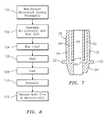
Fig. 7 is a sectional representation of a portion of a turbine blade that contains microcircuit cooling passages on both the pressure side and the suction side of an airfoil portion; and -
Fig. 8 is a flow chart illustrating the process for forming a turbine blade in accordance with the present disclosure; andFig. 9 is a sectional view of a turbine blade. -
Fig. 1 illustrates a portion of aturbine engine 10. As shown therein, theturbine engine 10 has a section which includes avane 12 having anairfoil portion 14 and ablade 16 having anairfoil portion 18. Thearea 20 shows the area which is to be discussed herein. -
Fig. 2 illustrates a portion of aturbine blade 16. As can be seen from this figure, theblade 16 has aplatform 22, aroot portion 24, and anairfoil portion 26. Theblade 16 has apressure side wall 28 and a suction side wall (not shown). Between thepressure side wall 28 and the suction side wall, there are one or more cores orcavities 30 through which a cooling fluid flows. Theplatform 22 has anupper surface 23 and alower surface 25. - High heat load applications may require one or more cooling circuits or microcircuits embedded within at least one of the
pressure side wall 28 and the suction side wall. These cooling circuits provide cooling and shielding from coolant heat pickup. The cooling circuits are formed during casting by using refractory metal cores to form thepassages Figs, 2 and9 . After theblade 16 has been cast, the cores are chemically removed, leaving the desired cooling circuits. Each of therefractory metal cores - As can be seen from
Fig. 2 , the region orarea 20 is not covered by any portion of themicrocircuit cooling passages uncovered area 20 along the airfoil root is subject to high thermal gradients. - As shown in
Fig. 3 , improved resistance to high thermal gradients can be provided by allowing themicrocircuit cooling passages platform 22 allowing better management of stress, gas flow and heat transfer. The microcircuit cooling passages may terminate in alocation 31 between theupper surface 23 and thelower surface 25 such as the mid-region of the thickness T. -
Fig. 4 is a sectional view of the pressure side taken along lines A - A inFig. 3 . As can be seen from this Figure, the microcircuit cooling passage(s) 32, 34 and/or 36 terminate in the vicinity of theplatform 22, while being embedded within thepressure side wall 28 within the platform thickness T. -
Fig. 5 illustrates thesuction side wall 29 of aturbine blade 16.Fig. 6 is a sectional view taken along lines B - B inFig. 5 . One or moremicrocircuit cooling passages 42 may be embedded within thesuction side wall 29. As can be seen from these figures, the cooling passage(s) 42 terminate in the vicinity of theplatform 22, such as in alocation 33 between theupper surface 23 and thelower surface 25 of theplatform 22 within the platform thickness T. - As previously discussed and as shown in
Fig. 7 , theturbine blade 16 has one or morecentral cores 44, through which cooling fluid flows. Eachrespective cooling circuit inlet 45 adjacent the terminal end of the cooling circuit in the platform region of the turbine blade which fluidly connects to arespective core 44. Theinlet 45 may be formed using any suitable technique known in the art, such as providing a refractory metal core with a curved configuration which forms theinlet 45. - The
turbine blade 16 may be formed using a lost molding technique as is known in the art. - The
microcircuit cooling passages microcircuit cooling passages - Referring now to
Fig. 8 , there is shown a flow chart of a process for forming a turbine engine component. Instep 100, therefractory metal cores step 102, the refractory metal cores are assembled with the main core. The refractory metal cores are positioned so that a terminal end of each refractory core is located in a region where a platform is to be formed. - In
step 104, wax is injected around the assembled cores to form a wax pattern. Instep 106, the wax pattern, with the cores, is dipped in a slurry which coats the wax pattern and forms a shell. After being formed, the shell is dried. The wax is then melted away to leave the shell to function as a mold. - In
step 108, the turbine engine component is cast by pouring molten material into the mold/shell. The molten metal is allowed to solidify. Instep 110, the turbine engine component with the cores is removed from the mold. Instep 112, the main core and the refractory metal cores are removed. The cores may be removed using any suitable technique known in the art. - While the process of the present disclosure has been described in the context of microcircuit cooling passages in an unshrouded turbine blade, the same process and features may also be used for microcircuit cooling passages in other turbine engine components such as static vanes and shrouded blades.
- It is apparent that there has been provided a microcircuit cooling passage in an airfoil portion of a turbine engine component. While the present process has been described in the context of specific embodiment(s) thereof, unforeseen alternatives, variations, and modifications may become apparent to those skilled in the art having read the foregoing description. It is intended to embrace those alternatives, modifications, and variations as fall within the broad scope of the appended claims.
Claims (15)
- A turbine engine component (16) comprising:an airfoil portion (26) having a platform (22), a pressure side wall (28), a suction side wall (29) and a root portion (24);at least one microcircuit cooling passage (32,34,36;42;60,62) embedded within in at least one of said pressure side wall (28) and said suction side wall (29); andeach said microcircuit cooling passage (32,34,36;42;60,62) providing cooling within an initial 10% span of said airfoil portion (26).
- The turbine engine component according to claim 1, wherein each said microcircuit cooling passage (32,34,36;42;60,62) terminates in a region adjacent said platform (22).
- The turbine engine component according to claim 1 or 2, wherein said platform (22) has a thickness (T) and each said microcircuit cooling passage (32,34,36;42;60,62) terminates within any portion of said thickness (T).
- The turbine engine component according to any preceding claim, wherein said at least one microcircuit cooling passage (32,34,36;60) is embedded within the pressure side wall.
- The turbine engine component according to any of claims 1 to 3, wherein said at least one microcircuit cooling passage (42;62) is embedded within the suction side wall (29).
- The turbine engine component according to any of claims 1 to 3, wherein the at least one cooling circuit includes a first microcircuit cooling passage (42;62) embedded within the suction side wall (29) and a second microcircuit cooling passage (32,34,36;60) embedded within the pressure side wall (28).
- The turbine engine component according to any preceding claim, further comprising at least one central core (44) and each said microcircuit cooling passage (60,62) having an inlet (45) which communicates with said at least one central core (44).
- The turbine engine component according to claim 7, wherein said inlet (45) is embedded within said platform (22).
- A process for forming a turbine engine component (16) comprising the steps of:providing a main core for forming a turbine engine component (16) having a platform (22); andpositioning at least one refractory metal core relative to said main core so that a terminal end of said at least one refractory metal core is located in a region where said platform (22) is to be formed.
- The process of claim 9, wherein said positioning step comprises positioning a plurality of refractory metal cores relative to said main core so that a terminal end of each said refractory metal core is located in a region where said platform (22) is to be formed.
- The process of claim 9 or 10, wherein said positioning step comprises positioning said at least one refractory metal core in a location where said at least one refractory metal core becomes embedded within a pressure side wall (28) of said turbine engine component (16).
- The process of claim 9 or 10, wherein said positioning step comprises positioning said at least one refractory metal core in a location where said at least one refractory metal core becomes embedded within a suction side wall (29) of said turbine engine component (16).
- The process of any of claims 9 to 12, wherein said positioning step comprises positioning said at least one refractory metal core so that each said refractory metal core terminates in a mid-region of a thickness (T) of the platform (22).
- The process of any of claims 9 to 13, further comprising forming at least one cooling circuit (32,34,36,42) by removing said at least one refractory metal core.
- The process of claim 14, further comprising removing said main core after said turbine engine component (16) has been cast.
Applications Claiming Priority (1)
| Application Number | Priority Date | Filing Date | Title |
|---|---|---|---|
| US12/774,771 US9121290B2 (en) | 2010-05-06 | 2010-05-06 | Turbine airfoil with body microcircuits terminating in platform |
Publications (3)
| Publication Number | Publication Date |
|---|---|
| EP2385216A2 true EP2385216A2 (en) | 2011-11-09 |
| EP2385216A3 EP2385216A3 (en) | 2014-02-19 |
| EP2385216B1 EP2385216B1 (en) | 2018-05-09 |
Family
ID=44244933
Family Applications (1)
| Application Number | Title | Priority Date | Filing Date |
|---|---|---|---|
| EP11157143.6A Active EP2385216B1 (en) | 2010-05-06 | 2011-03-07 | Turbine airfoil with body microcircuits terminating in platform |
Country Status (2)
| Country | Link |
|---|---|
| US (1) | US9121290B2 (en) |
| EP (1) | EP2385216B1 (en) |
Cited By (1)
| Publication number | Priority date | Publication date | Assignee | Title |
|---|---|---|---|---|
| WO2014165337A1 (en) | 2013-04-03 | 2014-10-09 | United Technologies Corporation | Variable thickness trailing edge cavity and method of making |
Families Citing this family (8)
| Publication number | Priority date | Publication date | Assignee | Title |
|---|---|---|---|---|
| US8753083B2 (en) * | 2011-01-14 | 2014-06-17 | General Electric Company | Curved cooling passages for a turbine component |
| US9296039B2 (en) | 2012-04-24 | 2016-03-29 | United Technologies Corporation | Gas turbine engine airfoil impingement cooling |
| US9243502B2 (en) | 2012-04-24 | 2016-01-26 | United Technologies Corporation | Airfoil cooling enhancement and method of making the same |
| US9422817B2 (en) | 2012-05-31 | 2016-08-23 | United Technologies Corporation | Turbine blade root with microcircuit cooling passages |
| EP3034803A1 (en) | 2014-12-16 | 2016-06-22 | Rolls-Royce Corporation | Hanger system for a turbine engine component |
| US10323524B2 (en) * | 2015-05-08 | 2019-06-18 | United Technologies Corporation | Axial skin core cooling passage for a turbine engine component |
| US10502066B2 (en) | 2015-05-08 | 2019-12-10 | United Technologies Corporation | Turbine engine component including an axially aligned skin core passage interrupted by a pedestal |
| US10753210B2 (en) * | 2018-05-02 | 2020-08-25 | Raytheon Technologies Corporation | Airfoil having improved cooling scheme |
Family Cites Families (13)
| Publication number | Priority date | Publication date | Assignee | Title |
|---|---|---|---|---|
| DE1066387B (en) | 1955-03-01 | 1959-10-01 | ||
| US6354797B1 (en) * | 2000-07-27 | 2002-03-12 | General Electric Company | Brazeless fillet turbine nozzle |
| US7131818B2 (en) * | 2004-11-02 | 2006-11-07 | United Technologies Corporation | Airfoil with three-pass serpentine cooling channel and microcircuit |
| US7467922B2 (en) * | 2005-07-25 | 2008-12-23 | Siemens Aktiengesellschaft | Cooled turbine blade or vane for a gas turbine, and use of a turbine blade or vane of this type |
| US7364405B2 (en) * | 2005-11-23 | 2008-04-29 | United Technologies Corporation | Microcircuit cooling for vanes |
| US7695246B2 (en) * | 2006-01-31 | 2010-04-13 | United Technologies Corporation | Microcircuits for small engines |
| US20080008599A1 (en) * | 2006-07-10 | 2008-01-10 | United Technologies Corporation | Integral main body-tip microcircuits for blades |
| EP1882819B1 (en) | 2006-07-18 | 2010-09-08 | United Technologies Corporation | Integrated platform, tip, and main body microcircuits for turbine blades |
| US7686582B2 (en) | 2006-07-28 | 2010-03-30 | United Technologies Corporation | Radial split serpentine microcircuits |
| US7527475B1 (en) * | 2006-08-11 | 2009-05-05 | Florida Turbine Technologies, Inc. | Turbine blade with a near-wall cooling circuit |
| US7927073B2 (en) * | 2007-01-04 | 2011-04-19 | Siemens Energy, Inc. | Advanced cooling method for combustion turbine airfoil fillets |
| US7712316B2 (en) * | 2007-01-09 | 2010-05-11 | United Technologies Corporation | Turbine blade with reverse cooling air film hole direction |
| US8105033B2 (en) * | 2008-06-05 | 2012-01-31 | United Technologies Corporation | Particle resistant in-wall cooling passage inlet |
-
2010
- 2010-05-06 US US12/774,771 patent/US9121290B2/en active Active
-
2011
- 2011-03-07 EP EP11157143.6A patent/EP2385216B1/en active Active
Non-Patent Citations (1)
| Title |
|---|
| None |
Cited By (2)
| Publication number | Priority date | Publication date | Assignee | Title |
|---|---|---|---|---|
| WO2014165337A1 (en) | 2013-04-03 | 2014-10-09 | United Technologies Corporation | Variable thickness trailing edge cavity and method of making |
| EP2981677A4 (en) * | 2013-04-03 | 2016-06-22 | United Technologies Corp | Variable thickness trailing edge cavity and method of making |
Also Published As
| Publication number | Publication date |
|---|---|
| US9121290B2 (en) | 2015-09-01 |
| EP2385216B1 (en) | 2018-05-09 |
| EP2385216A3 (en) | 2014-02-19 |
| US20110274559A1 (en) | 2011-11-10 |
Similar Documents
| Publication | Publication Date | Title |
|---|---|---|
| EP2385216B1 (en) | Turbine airfoil with body microcircuits terminating in platform | |
| US7731481B2 (en) | Airfoil cooling with staggered refractory metal core microcircuits | |
| EP1070829B1 (en) | Internally cooled airfoil | |
| US8734108B1 (en) | Turbine blade with impingement cooling cavities and platform cooling channels connected in series | |
| US7131817B2 (en) | Method and apparatus for cooling gas turbine engine rotor blades | |
| JP4731238B2 (en) | Apparatus for cooling a gas turbine engine rotor blade | |
| EP1726785B1 (en) | Turbine airfoil platform cooling circuit | |
| US8291963B1 (en) | Hybrid core assembly | |
| US7278827B2 (en) | Cooling air evacuation slots of turbine blades | |
| US7303375B2 (en) | Refractory metal core cooling technologies for curved leading edge slots | |
| US6915840B2 (en) | Methods and apparatus for fabricating turbine engine airfoils | |
| EP1936118A2 (en) | Turbine blade main core modifications for peripheral serpentine microcircuits | |
| EP1942251B1 (en) | Cooled airfoil having reduced trailing edge slot flow and corresponding casting method | |
| EP2532457A2 (en) | Hybrid core assembly for a casting process | |
| EP1055800A2 (en) | Turbine airfoil with internal cooling | |
| JP2007218262A5 (en) | ||
| EP2143512A1 (en) | Casting system for investment casting process | |
| EP1621725B1 (en) | Turbine rotor blade and gas turbine engine rotor assembly comprising such blades | |
| EP3594448B1 (en) | Airfoil with leading edge convective cooling system | |
| US7387492B2 (en) | Methods and apparatus for cooling turbine blade trailing edges | |
| US20250035000A1 (en) | Turbomachine vane provided with a cooling circuit and method for lost-wax manufacturing of such a vane | |
| CN105705265A (en) | Investment casting method for gas turbine engine vane segment | |
| US20200086380A1 (en) | Cast-in film cooling hole structures |
Legal Events
| Date | Code | Title | Description |
|---|---|---|---|
| AK | Designated contracting states |
Kind code of ref document: A2 Designated state(s): AL AT BE BG CH CY CZ DE DK EE ES FI FR GB GR HR HU IE IS IT LI LT LU LV MC MK MT NL NO PL PT RO RS SE SI SK SM TR |
|
| AX | Request for extension of the european patent |
Extension state: BA ME |
|
| PUAI | Public reference made under article 153(3) epc to a published international application that has entered the european phase |
Free format text: ORIGINAL CODE: 0009012 |
|
| PUAL | Search report despatched |
Free format text: ORIGINAL CODE: 0009013 |
|
| AK | Designated contracting states |
Kind code of ref document: A3 Designated state(s): AL AT BE BG CH CY CZ DE DK EE ES FI FR GB GR HR HU IE IS IT LI LT LU LV MC MK MT NL NO PL PT RO RS SE SI SK SM TR |
|
| AX | Request for extension of the european patent |
Extension state: BA ME |
|
| RIC1 | Information provided on ipc code assigned before grant |
Ipc: F01D 5/18 20060101AFI20140110BHEP |
|
| 17P | Request for examination filed |
Effective date: 20140815 |
|
| RBV | Designated contracting states (corrected) |
Designated state(s): AL AT BE BG CH CY CZ DE DK EE ES FI FR GB GR HR HU IE IS IT LI LT LU LV MC MK MT NL NO PL PT RO RS SE SI SK SM TR |
|
| 17Q | First examination report despatched |
Effective date: 20150226 |
|
| RAP1 | Party data changed (applicant data changed or rights of an application transferred) |
Owner name: UNITED TECHNOLOGIES CORPORATION |
|
| GRAP | Despatch of communication of intention to grant a patent |
Free format text: ORIGINAL CODE: EPIDOSNIGR1 |
|
| STAA | Information on the status of an ep patent application or granted ep patent |
Free format text: STATUS: GRANT OF PATENT IS INTENDED |
|
| INTG | Intention to grant announced |
Effective date: 20171122 |
|
| GRAS | Grant fee paid |
Free format text: ORIGINAL CODE: EPIDOSNIGR3 |
|
| GRAA | (expected) grant |
Free format text: ORIGINAL CODE: 0009210 |
|
| STAA | Information on the status of an ep patent application or granted ep patent |
Free format text: STATUS: THE PATENT HAS BEEN GRANTED |
|
| AK | Designated contracting states |
Kind code of ref document: B1 Designated state(s): AL AT BE BG CH CY CZ DE DK EE ES FI FR GB GR HR HU IE IS IT LI LT LU LV MC MK MT NL NO PL PT RO RS SE SI SK SM TR |
|
| REG | Reference to a national code |
Ref country code: GB Ref legal event code: FG4D |
|
| REG | Reference to a national code |
Ref country code: CH Ref legal event code: EP Ref country code: AT Ref legal event code: REF Ref document number: 997741 Country of ref document: AT Kind code of ref document: T Effective date: 20180515 |
|
| REG | Reference to a national code |
Ref country code: IE Ref legal event code: FG4D |
|
| REG | Reference to a national code |
Ref country code: DE Ref legal event code: R096 Ref document number: 602011048177 Country of ref document: DE |
|
| REG | Reference to a national code |
Ref country code: NL Ref legal event code: MP Effective date: 20180509 |
|
| REG | Reference to a national code |
Ref country code: LT Ref legal event code: MG4D |
|
| PG25 | Lapsed in a contracting state [announced via postgrant information from national office to epo] |
Ref country code: ES Free format text: LAPSE BECAUSE OF FAILURE TO SUBMIT A TRANSLATION OF THE DESCRIPTION OR TO PAY THE FEE WITHIN THE PRESCRIBED TIME-LIMIT Effective date: 20180509 Ref country code: SE Free format text: LAPSE BECAUSE OF FAILURE TO SUBMIT A TRANSLATION OF THE DESCRIPTION OR TO PAY THE FEE WITHIN THE PRESCRIBED TIME-LIMIT Effective date: 20180509 Ref country code: FI Free format text: LAPSE BECAUSE OF FAILURE TO SUBMIT A TRANSLATION OF THE DESCRIPTION OR TO PAY THE FEE WITHIN THE PRESCRIBED TIME-LIMIT Effective date: 20180509 Ref country code: NO Free format text: LAPSE BECAUSE OF FAILURE TO SUBMIT A TRANSLATION OF THE DESCRIPTION OR TO PAY THE FEE WITHIN THE PRESCRIBED TIME-LIMIT Effective date: 20180809 Ref country code: BG Free format text: LAPSE BECAUSE OF FAILURE TO SUBMIT A TRANSLATION OF THE DESCRIPTION OR TO PAY THE FEE WITHIN THE PRESCRIBED TIME-LIMIT Effective date: 20180809 Ref country code: LT Free format text: LAPSE BECAUSE OF FAILURE TO SUBMIT A TRANSLATION OF THE DESCRIPTION OR TO PAY THE FEE WITHIN THE PRESCRIBED TIME-LIMIT Effective date: 20180509 |
|
| PG25 | Lapsed in a contracting state [announced via postgrant information from national office to epo] |
Ref country code: GR Free format text: LAPSE BECAUSE OF FAILURE TO SUBMIT A TRANSLATION OF THE DESCRIPTION OR TO PAY THE FEE WITHIN THE PRESCRIBED TIME-LIMIT Effective date: 20180810 Ref country code: NL Free format text: LAPSE BECAUSE OF FAILURE TO SUBMIT A TRANSLATION OF THE DESCRIPTION OR TO PAY THE FEE WITHIN THE PRESCRIBED TIME-LIMIT Effective date: 20180509 Ref country code: RS Free format text: LAPSE BECAUSE OF FAILURE TO SUBMIT A TRANSLATION OF THE DESCRIPTION OR TO PAY THE FEE WITHIN THE PRESCRIBED TIME-LIMIT Effective date: 20180509 Ref country code: HR Free format text: LAPSE BECAUSE OF FAILURE TO SUBMIT A TRANSLATION OF THE DESCRIPTION OR TO PAY THE FEE WITHIN THE PRESCRIBED TIME-LIMIT Effective date: 20180509 Ref country code: LV Free format text: LAPSE BECAUSE OF FAILURE TO SUBMIT A TRANSLATION OF THE DESCRIPTION OR TO PAY THE FEE WITHIN THE PRESCRIBED TIME-LIMIT Effective date: 20180509 |
|
| REG | Reference to a national code |
Ref country code: AT Ref legal event code: MK05 Ref document number: 997741 Country of ref document: AT Kind code of ref document: T Effective date: 20180509 |
|
| PG25 | Lapsed in a contracting state [announced via postgrant information from national office to epo] |
Ref country code: CZ Free format text: LAPSE BECAUSE OF FAILURE TO SUBMIT A TRANSLATION OF THE DESCRIPTION OR TO PAY THE FEE WITHIN THE PRESCRIBED TIME-LIMIT Effective date: 20180509 Ref country code: RO Free format text: LAPSE BECAUSE OF FAILURE TO SUBMIT A TRANSLATION OF THE DESCRIPTION OR TO PAY THE FEE WITHIN THE PRESCRIBED TIME-LIMIT Effective date: 20180509 Ref country code: SK Free format text: LAPSE BECAUSE OF FAILURE TO SUBMIT A TRANSLATION OF THE DESCRIPTION OR TO PAY THE FEE WITHIN THE PRESCRIBED TIME-LIMIT Effective date: 20180509 Ref country code: DK Free format text: LAPSE BECAUSE OF FAILURE TO SUBMIT A TRANSLATION OF THE DESCRIPTION OR TO PAY THE FEE WITHIN THE PRESCRIBED TIME-LIMIT Effective date: 20180509 Ref country code: PL Free format text: LAPSE BECAUSE OF FAILURE TO SUBMIT A TRANSLATION OF THE DESCRIPTION OR TO PAY THE FEE WITHIN THE PRESCRIBED TIME-LIMIT Effective date: 20180509 Ref country code: EE Free format text: LAPSE BECAUSE OF FAILURE TO SUBMIT A TRANSLATION OF THE DESCRIPTION OR TO PAY THE FEE WITHIN THE PRESCRIBED TIME-LIMIT Effective date: 20180509 Ref country code: AT Free format text: LAPSE BECAUSE OF FAILURE TO SUBMIT A TRANSLATION OF THE DESCRIPTION OR TO PAY THE FEE WITHIN THE PRESCRIBED TIME-LIMIT Effective date: 20180509 |
|
| REG | Reference to a national code |
Ref country code: DE Ref legal event code: R097 Ref document number: 602011048177 Country of ref document: DE |
|
| PG25 | Lapsed in a contracting state [announced via postgrant information from national office to epo] |
Ref country code: IT Free format text: LAPSE BECAUSE OF FAILURE TO SUBMIT A TRANSLATION OF THE DESCRIPTION OR TO PAY THE FEE WITHIN THE PRESCRIBED TIME-LIMIT Effective date: 20180509 Ref country code: SM Free format text: LAPSE BECAUSE OF FAILURE TO SUBMIT A TRANSLATION OF THE DESCRIPTION OR TO PAY THE FEE WITHIN THE PRESCRIBED TIME-LIMIT Effective date: 20180509 |
|
| PLBE | No opposition filed within time limit |
Free format text: ORIGINAL CODE: 0009261 |
|
| STAA | Information on the status of an ep patent application or granted ep patent |
Free format text: STATUS: NO OPPOSITION FILED WITHIN TIME LIMIT |
|
| 26N | No opposition filed |
Effective date: 20190212 |
|
| PG25 | Lapsed in a contracting state [announced via postgrant information from national office to epo] |
Ref country code: SI Free format text: LAPSE BECAUSE OF FAILURE TO SUBMIT A TRANSLATION OF THE DESCRIPTION OR TO PAY THE FEE WITHIN THE PRESCRIBED TIME-LIMIT Effective date: 20180509 |
|
| PG25 | Lapsed in a contracting state [announced via postgrant information from national office to epo] |
Ref country code: MC Free format text: LAPSE BECAUSE OF FAILURE TO SUBMIT A TRANSLATION OF THE DESCRIPTION OR TO PAY THE FEE WITHIN THE PRESCRIBED TIME-LIMIT Effective date: 20180509 |
|
| REG | Reference to a national code |
Ref country code: CH Ref legal event code: PL |
|
| PG25 | Lapsed in a contracting state [announced via postgrant information from national office to epo] |
Ref country code: LU Free format text: LAPSE BECAUSE OF NON-PAYMENT OF DUE FEES Effective date: 20190307 Ref country code: AL Free format text: LAPSE BECAUSE OF FAILURE TO SUBMIT A TRANSLATION OF THE DESCRIPTION OR TO PAY THE FEE WITHIN THE PRESCRIBED TIME-LIMIT Effective date: 20180509 |
|
| REG | Reference to a national code |
Ref country code: BE Ref legal event code: MM Effective date: 20190331 |
|
| PG25 | Lapsed in a contracting state [announced via postgrant information from national office to epo] |
Ref country code: LI Free format text: LAPSE BECAUSE OF NON-PAYMENT OF DUE FEES Effective date: 20190331 Ref country code: IE Free format text: LAPSE BECAUSE OF NON-PAYMENT OF DUE FEES Effective date: 20190307 Ref country code: CH Free format text: LAPSE BECAUSE OF NON-PAYMENT OF DUE FEES Effective date: 20190331 |
|
| PG25 | Lapsed in a contracting state [announced via postgrant information from national office to epo] |
Ref country code: BE Free format text: LAPSE BECAUSE OF NON-PAYMENT OF DUE FEES Effective date: 20190331 |
|
| PG25 | Lapsed in a contracting state [announced via postgrant information from national office to epo] |
Ref country code: TR Free format text: LAPSE BECAUSE OF FAILURE TO SUBMIT A TRANSLATION OF THE DESCRIPTION OR TO PAY THE FEE WITHIN THE PRESCRIBED TIME-LIMIT Effective date: 20180509 |
|
| PG25 | Lapsed in a contracting state [announced via postgrant information from national office to epo] |
Ref country code: PT Free format text: LAPSE BECAUSE OF FAILURE TO SUBMIT A TRANSLATION OF THE DESCRIPTION OR TO PAY THE FEE WITHIN THE PRESCRIBED TIME-LIMIT Effective date: 20180910 Ref country code: MT Free format text: LAPSE BECAUSE OF NON-PAYMENT OF DUE FEES Effective date: 20190307 |
|
| PG25 | Lapsed in a contracting state [announced via postgrant information from national office to epo] |
Ref country code: CY Free format text: LAPSE BECAUSE OF FAILURE TO SUBMIT A TRANSLATION OF THE DESCRIPTION OR TO PAY THE FEE WITHIN THE PRESCRIBED TIME-LIMIT Effective date: 20180509 |
|
| PG25 | Lapsed in a contracting state [announced via postgrant information from national office to epo] |
Ref country code: IS Free format text: LAPSE BECAUSE OF FAILURE TO SUBMIT A TRANSLATION OF THE DESCRIPTION OR TO PAY THE FEE WITHIN THE PRESCRIBED TIME-LIMIT Effective date: 20180909 |
|
| PG25 | Lapsed in a contracting state [announced via postgrant information from national office to epo] |
Ref country code: HU Free format text: LAPSE BECAUSE OF FAILURE TO SUBMIT A TRANSLATION OF THE DESCRIPTION OR TO PAY THE FEE WITHIN THE PRESCRIBED TIME-LIMIT; INVALID AB INITIO Effective date: 20110307 |
|
| PG25 | Lapsed in a contracting state [announced via postgrant information from national office to epo] |
Ref country code: MK Free format text: LAPSE BECAUSE OF FAILURE TO SUBMIT A TRANSLATION OF THE DESCRIPTION OR TO PAY THE FEE WITHIN THE PRESCRIBED TIME-LIMIT Effective date: 20180509 |
|
| REG | Reference to a national code |
Ref country code: DE Ref legal event code: R081 Ref document number: 602011048177 Country of ref document: DE Owner name: RAYTHEON TECHNOLOGIES CORPORATION (N.D.GES.D.S, US Free format text: FORMER OWNER: UNITED TECHNOLOGIES CORPORATION, FARMINGTON, CONN., US Ref country code: DE Ref legal event code: R081 Ref document number: 602011048177 Country of ref document: DE Owner name: RTX CORPORATION (N.D.GES.D. STAATES DELAWARE),, US Free format text: FORMER OWNER: UNITED TECHNOLOGIES CORPORATION, FARMINGTON, CONN., US |
|
| P01 | Opt-out of the competence of the unified patent court (upc) registered |
Effective date: 20230519 |
|
| REG | Reference to a national code |
Ref country code: DE Ref legal event code: R081 Ref document number: 602011048177 Country of ref document: DE Owner name: RTX CORPORATION (N.D.GES.D. STAATES DELAWARE),, US Free format text: FORMER OWNER: RAYTHEON TECHNOLOGIES CORPORATION (N.D.GES.D.STAATES DELAWARE), ARLINGTON, VA, US |
|
| PGFP | Annual fee paid to national office [announced via postgrant information from national office to epo] |
Ref country code: GB Payment date: 20260220 Year of fee payment: 16 |
|
| PGFP | Annual fee paid to national office [announced via postgrant information from national office to epo] |
Ref country code: DE Payment date: 20260219 Year of fee payment: 16 |
|
| PGFP | Annual fee paid to national office [announced via postgrant information from national office to epo] |
Ref country code: FR Payment date: 20260219 Year of fee payment: 16 |