EP2385165A1 - Steam generator comprising a liquid level sensor and method of determining a liquid level in a tank - Google Patents
Steam generator comprising a liquid level sensor and method of determining a liquid level in a tank Download PDFInfo
- Publication number
- EP2385165A1 EP2385165A1 EP10161769A EP10161769A EP2385165A1 EP 2385165 A1 EP2385165 A1 EP 2385165A1 EP 10161769 A EP10161769 A EP 10161769A EP 10161769 A EP10161769 A EP 10161769A EP 2385165 A1 EP2385165 A1 EP 2385165A1
- Authority
- EP
- European Patent Office
- Prior art keywords
- liquid level
- electrode
- level sensing
- sensing electrode
- steam generator
- Prior art date
- Legal status (The legal status is an assumption and is not a legal conclusion. Google has not performed a legal analysis and makes no representation as to the accuracy of the status listed.)
- Withdrawn
Links
- 239000007788 liquid Substances 0.000 title claims abstract description 237
- 238000000034 method Methods 0.000 title claims description 11
- 238000013016 damping Methods 0.000 claims abstract description 18
- XLYOFNOQVPJJNP-UHFFFAOYSA-N water Substances O XLYOFNOQVPJJNP-UHFFFAOYSA-N 0.000 claims description 83
- 238000001914 filtration Methods 0.000 claims description 22
- 238000001035 drying Methods 0.000 claims description 5
- 238000005406 washing Methods 0.000 claims description 3
- 238000005259 measurement Methods 0.000 description 32
- 238000009835 boiling Methods 0.000 description 11
- 238000010276 construction Methods 0.000 description 4
- 230000001419 dependent effect Effects 0.000 description 2
- 238000010438 heat treatment Methods 0.000 description 2
- 238000009736 wetting Methods 0.000 description 2
- 230000003213 activating effect Effects 0.000 description 1
- 238000001514 detection method Methods 0.000 description 1
- 230000000694 effects Effects 0.000 description 1
- 230000002708 enhancing effect Effects 0.000 description 1
- 230000030279 gene silencing Effects 0.000 description 1
- 230000007257 malfunction Effects 0.000 description 1
- 238000010025 steaming Methods 0.000 description 1
Images


Classifications
-
- D—TEXTILES; PAPER
- D06—TREATMENT OF TEXTILES OR THE LIKE; LAUNDERING; FLEXIBLE MATERIALS NOT OTHERWISE PROVIDED FOR
- D06F—LAUNDERING, DRYING, IRONING, PRESSING OR FOLDING TEXTILE ARTICLES
- D06F39/00—Details of washing machines not specific to a single type of machines covered by groups D06F9/00 - D06F27/00
- D06F39/40—Steam generating arrangements
-
- D—TEXTILES; PAPER
- D06—TREATMENT OF TEXTILES OR THE LIKE; LAUNDERING; FLEXIBLE MATERIALS NOT OTHERWISE PROVIDED FOR
- D06F—LAUNDERING, DRYING, IRONING, PRESSING OR FOLDING TEXTILE ARTICLES
- D06F34/00—Details of control systems for washing machines, washer-dryers or laundry dryers
- D06F34/14—Arrangements for detecting or measuring specific parameters
-
- D—TEXTILES; PAPER
- D06—TREATMENT OF TEXTILES OR THE LIKE; LAUNDERING; FLEXIBLE MATERIALS NOT OTHERWISE PROVIDED FOR
- D06F—LAUNDERING, DRYING, IRONING, PRESSING OR FOLDING TEXTILE ARTICLES
- D06F58/00—Domestic laundry dryers
- D06F58/20—General details of domestic laundry dryers
- D06F58/203—Laundry conditioning arrangements
-
- D—TEXTILES; PAPER
- D06—TREATMENT OF TEXTILES OR THE LIKE; LAUNDERING; FLEXIBLE MATERIALS NOT OTHERWISE PROVIDED FOR
- D06F—LAUNDERING, DRYING, IRONING, PRESSING OR FOLDING TEXTILE ARTICLES
- D06F2103/00—Parameters monitored or detected for the control of domestic laundry washing machines, washer-dryers or laundry dryers
- D06F2103/60—Parameters monitored or detected for the control of domestic laundry washing machines, washer-dryers or laundry dryers related to auxiliary conditioning or finishing agents, e.g. filling level of perfume tanks
- D06F2103/62—Parameters monitored or detected for the control of domestic laundry washing machines, washer-dryers or laundry dryers related to auxiliary conditioning or finishing agents, e.g. filling level of perfume tanks related to systems for water or steam used for conditioning or finishing
Definitions
- the present application is directed to a steam generator comprising a liquid level sensor, a laundry machine comprising such steam generator and method of determining a liquid level in a tank.
- a liquid level sensor i. e. a water level sensor for a boiler tank of a steam generator is known for example from W02006/126778 A1 .
- the water level sensor comprises two sensing electrodes and a reference electrode which are strip shaped.
- a stability maintaining plate to which the electrodes are mounted to is provided in order to shield the electrodes from pronounced water level fluctuations, which may falsify water level determination.
- EP 1 507 031 A1 and EP 1 507 029 A2 also disclose water level sensors for a boiler tank.
- the water level sensor has two sensing electrodes and a reference electrode, which are all rod shaped.
- a tube comprising longitudinal slots surrounds the sensing and reference electrodes and protects them against water level fluctuations induced by boiling water.
- a steam generator comprising a liquid level sensor for sensing the liquid level in a tank, preferably the water level in a boiler tank, is provided. Signals generated by the liquid level sensor may be used to determine the liquid level in the tank, in particular boiler tank.
- Such a steam generator may be part of an appliance, in particular a laundry machine such as a washing and/or drying machine, requiring the generation of steam applied to cloths for drying, refreshing, de-wrinkling, washing purpose.
- the laundry machine can comprise a rotatable drum or a stationary cabinet for containing the clothes.
- the liquid level sensor comprises at least one liquid level sensing electrode and at least one damping element.
- the damping element is adapted and designed for damping fluctuations in the liquid level at least in a space between the at least one liquid level sensing electrode and the damping element. Fluctuations in the liquid level within a boiler tank mainly are due to turbulences of boiling water. As to tanks in general, other disturbances may occur, such as turbulences occurring during feeding liquid into the tank. If such turbulences hit the sensing electrode/s unattenuated the liquid level/s determined on the basis of liquid level sensor signals will probably be erroneous.
- the at least one damping element is implemented as a reference electrode of the liquid level sensor.
- a reference electrode of the liquid level sensor Such a construction is of comparatively easy design yet allowing accurate and reliable liquid level sensing and determination.
- the space between reference electrode and liquid level sensing electrode/s can be considered as a measurement volume.
- the damping element i. e. the reference electrode, keeps the measurement volume from extensive liquid level fluctuations.
- the liquid level sensor may comprise a first liquid level sensing electrode for sensing a lower liquid level, and a second liquid level sensing electrode for sensing an upper liquid level, and preferably a third liquid level sensing electrode for sensing a maximally admissible liquid level in the tank.
- a liquid level signal of the first liquid level sensing electrode indicates a low liquid level
- a valve may be automatically activated to supply liquid to the tank from a feed line connected thereto.
- the valve may be automatically deactivated thereby stopping supply of liquid.
- water boiling tanks have steam exit openings fluidly connected to the tub/drum.
- a third liquid level sensing electrode for sensing a maximal admissible liquid level so as to prevent water from exiting the boiling tank and entering the drum thereby wetting the laundry contained therein. If due to a failure of the second liquid level electrode, the liquid level reaches the maximal admissible liquid level, the respective liquid level signal can be used to automatically close the valve.
- steamers, steam generators, steam dryers, in particular laundry steam dryers, and the like steam is usually directly guided into a steam or drying chamber so that it is quite disadvantageous if water exits the boiler tank.
- the electrodes may be configured as follows: the first liquid level sensing electrode or at least a lower tip end thereof is arranged at a lower level than the second liquid level sensing electrode, and the second liquid level sensing electrode or at least a lower tip end thereof is arranged at a lower level than the third liquid level sensing electrode.
- the electrodes extend horizontally at respective different horizontal levels.
- the electrodes extend vertically and lower tip ends of the electrodes are arranged at respective different horizontal levels. If required, both configurations may be mixed, in particular if several liquid level sensing electrodes are provided. It is preferred that the lower tip end of the reference electrode is flush with or at least approximately flush with the first liquid level sensing electrode or the lower tip end thereof.
- the at least one liquid level sensing electrode preferably a single liquid level sensing electrode, continuously runs along the reference electrode in lengthwise direction, at least over a section thereof, and in the ordinary operational state of the liquid level sensor a lower tip end of the liquid level sensing electrode is approximately flush with at least one lower edge or tip end of the at least one reference electrode.
- the liquid level can be determined or measured continuously, preferably with a single liquid level sensing electrode.
- a continuous measurement of the liquid level does not require liquid level sensing electrodes at different levels.
- the continuous measurement is a kind of analogous measurement in contrast to the above mentioned kind of digital measurement using liquid level sensing electrodes arranged at different levels.
- the at least one liquid level sensing electrode and reference electrode of this alternate configuration may be of plate or sheet like design and, for example arranged in parallel in a mutually congruent configuration.
- the liquid level sensor of this alternate configuration is of comparatively simple construction yet allowing accurate and reliable liquid level determination.
- all, several or each of the at least one liquid level sensing electrode are/is arranged between at least two reference electrodes.
- the measurement volume in this case is composed of respective volumes between the reference electrodes and the at least one liquid level sensing electrode.
- the measuring volume or partial volumes thereof can have a polyhedron, in particular cuboid, or cylindrical structure.
- the reference electrodes at least partially surround all, several or a single liquid level sensing electrode, i. e. the reference electrodes at least partially surround and define the measuring volume.
- Using several reference electrodes has the advantage that the measuring volume can be shielded from liquid level fluctuations more effectively.
- a distance between the at least one liquid level sensing electrode and at least one adjacent reference electrode lies in the rage of 1 to 10 mm. Such distances are effective in silencing liquid level fluctuations in the measuring volume.
- the at least one liquid level sensing electrode, in particular the first to third liquid level sensing electrodes, and the reference electrode can be selected from the group: bar electrode, strip electrode, flat electrode, surface electrode, plate electrode, hollow profile electrode of circular, oval or polygonal cross section, in particular cup-shaped electrode, hollow rod shaped electrode and hollow polyhedron shaped, in particular cuboid shaped, electrode.
- the liquid level sensing electrodes i. e. the first to third liquid level electrodes
- the reference electrode can be a flat or plate electrode facing the liquid level sensing electrodes.
- the liquid level sensing electrodes can be sandwiched between pairs of plate or flat reference electrodes. It is also possible to use a cup-shaped, hollow rod shaped or hollow polyhedron shaped reference electrode accommodating therein the liquid level sensing electrodes.
- the liquid sensing electrode/s preferably are surface or plate electrodes.
- the reference electrode/s preferably is/are of the same type, preferably facing a respective liquid sensing electrode in a parallel configuration.
- a respective liquid level sensing electrode can be sandwiched between pairs of flat or plate reference electrodes.
- the reference electrode is a cup-shaped, hollow rod shaped or hollow polyhedron shaped electrode accommodating therein the at least one liquid level sensing electrode.
- the at least one reference electrode may be a hollow profile electrode or comprise one or several elongate hollow profile sections respectively accommodating at least one of the at least one liquid level sensing electrode.
- the reference electrode may have several duct or channel like sections each accommodating either a single one or several of the at least one reference electrode.
- the liquid level sensor can further comprise a signal processing unit having an electronic signal filter unit for applying an electronic filtering operation to liquid level sensor signals generated by the at least one liquid level sensor.
- a filtering operation is useful for reducing noise in liquid level senor signals.
- the liquid level may accurately and reliably be determined.
- the electronic filter unit is adapted to apply at least one of a low pass filtering operation, preferably of 2 nd order, a Butterworth filtering operation and Chebyshev filtering operation to the liquid level sensor signals.
- a low pass filtering operation preferably of 2 nd order
- a Butterworth filtering operation preferably of 2 nd order
- Chebyshev filtering operation turned out to be effective in reducing noise.
- a device in particular a steamer, steam generator or steam dryer is provided which comprises a boiler tank and a liquid level sensor of any configuration described so far.
- a method of determining a liquid level, in particular a water level, in a boiler tank of preferably a steamer, steam generator or steam dryer is provided.
- at least one liquid level sensing signal is generated by at least one liquid level sensor of any configuration described so far and the liquid level is determined based on the at least one liquid level sensing signal measured between at least one of the at least one liquid level sensing electrode and at least one of the at least one reference electrode.
- the liquid level can be accurately determined.
- the method can be based on a digital type of measurement, in which the liquid level is determined based on a fixed number of discrete liquid level sensing signals each being measured between a respective liquid level sensing electrode representative of a preset discrete liquid level and one or at least one of the at least one reference electrode.
- the method can be based on an analog type of measurement.
- the liquid level is determined based on at least one, preferably a single, liquid level sensing signal respectively continuously measured between a liquid level sensing electrode and at least one reference electrode.
- an electronic filtering operation preferably a low pass filter operation, in particular of 2 nd order, a Butterworth filtering operation or a Chebyshev filtering operation can be applied to the at least one measured liquid level sensing signal.
- a low pass filter operation in particular of 2 nd order, a Butterworth filtering operation or a Chebyshev filtering operation
- the liquid level can be satisfactory determined on the basis of the filtered liquid level sensing signal/s.
- FIG 1 schematically shows a steam dryer 1 comprising a boiler tank 2 which in turn comprises a liquid level sensor 3.
- the boiler tank 2 is connected via a first hose 4 with a faucet (not shown) in order to feed water to the boiler tank 2.
- the boiler tank 2 comprises a heating coil (not shown) or something similar arranged at the inner bottom side of the boiler tank 2 and intended to boil water accommodated in the boiler tank 2 thus generating steam.
- the steam leaves the boiling tank 2 via an opening to which a first end of a second hose 5 is connected.
- the second end of the second hose 5 is fluidly connected to a laundry tub 6 and/or to a drum such that steam can be guided from the boiler tank 2 to the drum for steaming laundry accommodated therein, for example.
- the heating coil may be damaged. It is therefore desirable to automatically feed water via the first hose 4 into the boiler tank 2 if the water level falls below a lower threshold. Further, if the water level reaches an adequate filling level it is desirable to automatically stop water supply. It is further desirable to assure that no liquid water enters the laundry tub 6 via the second hose 5.
- the liquid level sensor 3 which is used for sensing and determining the water level prevailing in the boiler tank 2.
- Water supply may be activated or deactivated on the basis of respective water levels sensed or determined, in order to keep the water level within preset limits.
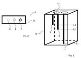
- FIG 2 shows a bottom view of the liquid level sensor 3 of a first configuration.
- the liquid level sensor 3 comprises a first liquid level sensing electrode 7, a second liquid level sensing electrode 8 and a third liquid level sensing electrode 9. Further, the liquid level sensor 3 comprises a reference electrode 10.
- FIG 3 shows a perspective view of the liquid level sensor 3 of the first configuration.
- the reference electrode 10 is a cup shaped or cuboid shaped hollow electrode accommodating therein the first to third liquid level sensing electrode 7, 8, 9.
- the top of the reference electrode 10 can comprises two equalizing openings 11, which however are not necessary for the present invention.
- the function of the liquid level sensor 3 is as follows:
- the first liquid level sensing electrode 7 If the water level within the boiler tank 2 drops or lies below a first water level L1 which in the present case corresponds to the bottom level of the reference electrode, the first liquid level sensing electrode 7 generates a signal. Note that the lower tip end of the first liquid level sensing electrode 7 is flush with the lower bottom of the reference electrode 10.
- This signal from the first liquid level sensing electrode 7 is used to automatically activate water supply to the boiler tank 2 via the first hose 4, by activating a valve for example. As a consequence, the water level within the boiler tank 2 and also the water level within the reference electrode 10 rises.
- the second liquid level sensing electrode 8 If the water level reaches a second water level L2, lying at a higher level than the first water level L1, the second liquid level sensing electrode 8, the lower tip end of which is roughly level with the second water level L2, generates a signal indicative of the second water level L2.
- the second water level L2 in the present case represents an upper filling level which shall not be exceeded during normal operation. Hence, in this situation the water supply is deactivated based on at least the signal of the second liquid level sensing electrode 8.
- the second liquid level sensing electrode 8 fails to detect that the water level is at second water level L2 or even higher, or in case of some malfunctions of the water supply valve adapted to supply to the boiler tank 2, the water supply will not be stopped. Therefore, there is provided the third liquid level sensing electrode 9 generating a signal if the water level reaches or exceeds a third water level L3 which is a maximal admissible water level up to which water can reliably be prevented from entering the laundry tub 6.
- liquid level sensor 3 works with discrete water levels L1 to L3 and hence implements a kind of digital measurement.
- first to third liquid level sensing electrode 7, 8, 9 are rod shaped. However, other shapes are also possible. If required, the first to third liquid sensing electrodes 7, 8, 9 may respectively comprise a sheathing covering the outer surface thereof except for respective lower tip ends.
- the reference electrode 10 acts as a damping element preventing or shielding the inner of the reference electrode, i. e. the measurement volume, from water level fluctuations induced by boiling water. This is mainly due to the fact that the reference electrode 10 surrounds the first to third liquid level sensing electrode 7, 8, 9. As the reference electrode 10 itself greatly damps or absorbs fluctuations in the water level, no additional provisions are required for shielding or protecting the first to third liquid level sensing electrode 7, 8, 9. Hence, the liquid level sensor 3 is of comparatively simple construction yet enabling accurate and reliable detection of the water level in the boiling tank 2.
- FIG 4 shows a bottom view of the liquid level sensor 3 of the second configuration
- FIG 5 shows a perspective view thereof.
- the present liquid level sensor 3 has only one liquid level sensing electrode which is referred to as analog liquid level electrode 12 for the reasons given below.
- the reference electrode 10 is a hollow profile electrode with a cuboid-like inner volume.
- the reference electrode 10 surrounds the analog liquid level electrode 12 and greatly damps or silences boiling induced water level fluctuations and others.
- a further difference to the configuration in FIG 1 is that the water level in the boiler tank 2 is sensed continuously corresponding to an analog type of measurement. Based on the analog signal, water supply to the boiler tank 2 is enabled or disabled if the analog signal indicates a low water level or a sufficiently high water level, respectively. This is quite similar the operation mode described in connection with FIG 1 to FIG 3 .
- the cup-shaped hollow profile reference electrode 10 shown in FIG 2 to 5 may be of other design.
- the cross section of the reference electrode 10 may also be circular or oval.
- the reference electrode 10 has one or more planar or curved sections surrounding the liquid level sensing electrodes 7, 8, 9 and 12 at least partially.
- the reference electrode may be a cylinder or cuboid half shell.
- the reference electrode 10 comprises several plate electrodes defining a cube around the liquid level sensing electrodes 7, 8, 9 and 12. Further, it may be contemplated to omit one or more of the aforementioned plate electrodes. This means that the reference electrode 10 can comprise four, three, two or just one plate electrode.
- two or more plate electrodes are equal sized and that two adjacent plate electrodes are arranged face to face in parallel orientation or are mutually inclined.
- Other sizes, arrangements and orientations are possible that make it possible to damp or absorb water level fluctuations in the measurement volume.
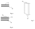
- FIG 6 and FIG 7 show a bottom and perspective view of a liquid level sensor 3 of a third configuration.
- the present arrangement differs from the one shown in FIG 4 and FIG 5 in that the analog liquid level electrode 12 is not surrounded by the reference electrode 10. Rather, both the reference electrode 10 and the analog liquid level electrode 12 are plate electrodes arranged in parallel in a face to face orientation.
- the measuring volume presently is defined by the space/gap between the reference electrode 10 and the analog liquid level electrode 12 and represents a laterally open cuboid.
- the reference electrode 10 acts as a damping element as, due to the parallel face to face arrangement of both electrodes 10 and 12, the measurement volume is less accessible from the outside, in particular for turbulences occurring during boiling.
- the analog liquid level electrode 12 contributes to reduce water level fluctuations.
- the measurement volume between the reference electrode 10 and analog liquid level electrode 12 may have any shape and form suitable for at least reducing water level fluctuations in the measurement volume, i. e. damping water level fluctuations impinging on the measurement volume from the outside.
- the electrodes 10 and 12 may have surfaces facing each other and being corrugated or otherwise shaped in order to reduce, damp or silence boiling induced water level fluctuations in the measurement volume.
- a further reference electrode 10 can be provided as is shown in FIG 8 .
- the further reference electrode 10 is arranged comparable to the one shown in FIG 6 and FIG 7 , but positioned at the opposite side of the analog liquid level electrode 12. Therefore, the measurement volume extends to two opposite sides of the analog liquid level electrode 12, which of course leads to enhanced measurement results and enhanced accuracy.
- a distance (space/gap) between each of the reference electrodes 10 and the analog liquid level electrode 12 is in the range of one to several millimeters, which also applies to the configuration of FIG 6 and Fig 7 . Note that smaller or larger distances may be used if required.
- a still further possibility to enhance accuracy of measuring is to apply a filtering operation to the liquid level signal.
- a filtering operation may be applied with any of the above configurations.
- a filtering operation is especially suitable for analog measurements. This is due to the fact that an analog measurement requires continuous measurement of the water level, which measurement may be prone to noise. Noise can be greatly reduced by applying a low pass filter operation to the signals.
- the low pass filter operation preferably is of 2 nd order. Reference is made to the description above in which a formula for 2 nd order low pass filtering is given exemplarily.
- Butterworth or Chebyshev filters can be applied.
- the filter operation or other signal processing can be carried out by a signal processing unit (not shown) which may be integral with the liquid level sensor 3 or connected thereto from a remote location.
Landscapes
- Engineering & Computer Science (AREA)
- Textile Engineering (AREA)
- Measurement Of Levels Of Liquids Or Fluent Solid Materials (AREA)
- Control Of Washing Machine And Dryer (AREA)
Abstract
The present application in particular is directed to a steam generator for laundry machine comprising a liquid level sensor 3 for a boiler tank 2. The sensor 3 comprises at least one liquid level sensing electrode and at least one damping element for damping fluctuations in the liquid level at least in a space between the at least one liquid level sensing electrode and the damping element, wherein the at least one damping element is implemented as a reference electrode of the liquid level sensor 3.
Description
- The present application is directed to a steam generator comprising a liquid level sensor, a laundry machine comprising such steam generator and method of determining a liquid level in a tank.
- A liquid level sensor, i. e. a water level sensor for a boiler tank of a steam generator is known for example from
W02006/126778 A1 . The water level sensor comprises two sensing electrodes and a reference electrode which are strip shaped. A stability maintaining plate to which the electrodes are mounted to is provided in order to shield the electrodes from pronounced water level fluctuations, which may falsify water level determination. -
EP 1 507 031 A1 andEP 1 507 029 A2 also disclose water level sensors for a boiler tank. The water level sensor has two sensing electrodes and a reference electrode, which are all rod shaped. A tube comprising longitudinal slots surrounds the sensing and reference electrodes and protects them against water level fluctuations induced by boiling water. - It is an object of the invention to provide an alternative liquid level sensor, in particular a water level sensor, of comparatively easy design and construction, for accurately and reliably sensing and detecting the liquid level even in extreme conditions prevailing in a tank, such as a boiler tank for example. Further, a device comprising such a liquid level sensor and a method of determining a liquid level in a tank, in particular a boiler tank, shall be provided.
- This object is achieved by
independent claims - According to
independent claim 1, a steam generator comprising a liquid level sensor for sensing the liquid level in a tank, preferably the water level in a boiler tank, is provided. Signals generated by the liquid level sensor may be used to determine the liquid level in the tank, in particular boiler tank. - Such a steam generator may be part of an appliance, in particular a laundry machine such as a washing and/or drying machine, requiring the generation of steam applied to cloths for drying, refreshing, de-wrinkling, washing purpose. The laundry machine can comprise a rotatable drum or a stationary cabinet for containing the clothes.
- The liquid level sensor comprises at least one liquid level sensing electrode and at least one damping element. The damping element is adapted and designed for damping fluctuations in the liquid level at least in a space between the at least one liquid level sensing electrode and the damping element. Fluctuations in the liquid level within a boiler tank mainly are due to turbulences of boiling water. As to tanks in general, other disturbances may occur, such as turbulences occurring during feeding liquid into the tank. If such turbulences hit the sensing electrode/s unattenuated the liquid level/s determined on the basis of liquid level sensor signals will probably be erroneous.
- With the proposed liquid level sensor, the at least one damping element is implemented as a reference electrode of the liquid level sensor. Such a construction is of comparatively easy design yet allowing accurate and reliable liquid level sensing and determination. Note that the space between reference electrode and liquid level sensing electrode/s can be considered as a measurement volume. In this respect, the damping element, i. e. the reference electrode, keeps the measurement volume from extensive liquid level fluctuations.
- In one configuration, the liquid level sensor may comprise a first liquid level sensing electrode for sensing a lower liquid level, and a second liquid level sensing electrode for sensing an upper liquid level, and preferably a third liquid level sensing electrode for sensing a maximally admissible liquid level in the tank. Here, if a liquid level signal of the first liquid level sensing electrode indicates a low liquid level, a valve may be automatically activated to supply liquid to the tank from a feed line connected thereto. Further, if a liquid level signal of the second liquid level sensing electrode indicates an upper liquid level, the valve may be automatically deactivated thereby stopping supply of liquid.
- Generally, in laundry machine such as washer, washer-dryer, tumble dryer, water boiling tanks have steam exit openings fluidly connected to the tub/drum. it may be advantageous to have a third liquid level sensing electrode for sensing a maximal admissible liquid level so as to prevent water from exiting the boiling tank and entering the drum thereby wetting the laundry contained therein. If due to a failure of the second liquid level electrode, the liquid level reaches the maximal admissible liquid level, the respective liquid level signal can be used to automatically close the valve. With steamers, steam generators, steam dryers, in particular laundry steam dryers, and the like, steam is usually directly guided into a steam or drying chamber so that it is quite disadvantageous if water exits the boiler tank. Because in this case the water would directly flow into the chamber and unintentionally wetting objects placed therein. In providing the third liquid level sensing electrode the likelihood of water entering the chamber in case of failure of the second liquid level sensing electrode can be drastically reduced. Note that the principles set out before apply mutatis mutandis to any tank having an upper opening and with which any liquid overflow shall be prevented during filling.
- With respect to the ordinary operational state of the liquid level sensor, the electrodes may be configured as follows: the first liquid level sensing electrode or at least a lower tip end thereof is arranged at a lower level than the second liquid level sensing electrode, and the second liquid level sensing electrode or at least a lower tip end thereof is arranged at a lower level than the third liquid level sensing electrode. Hence it is in particular possible that the electrodes extend horizontally at respective different horizontal levels. In the alternative the electrodes extend vertically and lower tip ends of the electrodes are arranged at respective different horizontal levels. If required, both configurations may be mixed, in particular if several liquid level sensing electrodes are provided. It is preferred that the lower tip end of the reference electrode is flush with or at least approximately flush with the first liquid level sensing electrode or the lower tip end thereof.
- In an alternate configuration of the liquid level sensor, the at least one liquid level sensing electrode, preferably a single liquid level sensing electrode, continuously runs along the reference electrode in lengthwise direction, at least over a section thereof, and in the ordinary operational state of the liquid level sensor a lower tip end of the liquid level sensing electrode is approximately flush with at least one lower edge or tip end of the at least one reference electrode. With such a configuration the liquid level can be determined or measured continuously, preferably with a single liquid level sensing electrode. A continuous measurement of the liquid level does not require liquid level sensing electrodes at different levels. The continuous measurement is a kind of analogous measurement in contrast to the above mentioned kind of digital measurement using liquid level sensing electrodes arranged at different levels. The at least one liquid level sensing electrode and reference electrode of this alternate configuration may be of plate or sheet like design and, for example arranged in parallel in a mutually congruent configuration. The liquid level sensor of this alternate configuration is of comparatively simple construction yet allowing accurate and reliable liquid level determination.
- In a preferred embodiment, all, several or each of the at least one liquid level sensing electrode are/is arranged between at least two reference electrodes. The measurement volume in this case is composed of respective volumes between the reference electrodes and the at least one liquid level sensing electrode. Dependent on the shape and mutual arrangement of the reference electrodes, the measuring volume or partial volumes thereof can have a polyhedron, in particular cuboid, or cylindrical structure. In particular it is possible that the reference electrodes at least partially surround all, several or a single liquid level sensing electrode, i. e. the reference electrodes at least partially surround and define the measuring volume. Using several reference electrodes has the advantage that the measuring volume can be shielded from liquid level fluctuations more effectively.
- In a further preferred embodiment, a distance between the at least one liquid level sensing electrode and at least one adjacent reference electrode lies in the rage of 1 to 10 mm. Such distances are effective in silencing liquid level fluctuations in the measuring volume.
- The at least one liquid level sensing electrode, in particular the first to third liquid level sensing electrodes, and the reference electrode can be selected from the group: bar electrode, strip electrode, flat electrode, surface electrode, plate electrode, hollow profile electrode of circular, oval or polygonal cross section, in particular cup-shaped electrode, hollow rod shaped electrode and hollow polyhedron shaped, in particular cuboid shaped, electrode.
- In the embodiment allowing digital liquid level measurement, the liquid level sensing electrodes, i. e. the first to third liquid level electrodes, preferably are bar or rod electrodes, and the reference electrode can be a flat or plate electrode facing the liquid level sensing electrodes. The liquid level sensing electrodes can be sandwiched between pairs of plate or flat reference electrodes. It is also possible to use a cup-shaped, hollow rod shaped or hollow polyhedron shaped reference electrode accommodating therein the liquid level sensing electrodes.
- With the embodiment allowing analog liquid level measurement, the liquid sensing electrode/s preferably are surface or plate electrodes. In this case, the reference electrode/s preferably is/are of the same type, preferably facing a respective liquid sensing electrode in a parallel configuration. Also, a respective liquid level sensing electrode can be sandwiched between pairs of flat or plate reference electrodes. However, in connection with the analogue measurement, it is also possible that the reference electrode is a cup-shaped, hollow rod shaped or hollow polyhedron shaped electrode accommodating therein the at least one liquid level sensing electrode.
- Other electrode configurations and mutual arrangements are conceivable that effectively reduce liquid level fluctuations in the measurement volume, as is the case with those mentioned beforehand. In particular, the at least one reference electrode may be a hollow profile electrode or comprise one or several elongate hollow profile sections respectively accommodating at least one of the at least one liquid level sensing electrode. Here, the reference electrode may have several duct or channel like sections each accommodating either a single one or several of the at least one reference electrode.
- The liquid level sensor can further comprise a signal processing unit having an electronic signal filter unit for applying an electronic filtering operation to liquid level sensor signals generated by the at least one liquid level sensor. Such a filtering operation is useful for reducing noise in liquid level senor signals. As a consequence, the liquid level may accurately and reliably be determined.
- In a preferred embodiment, the electronic filter unit is adapted to apply at least one of a low pass filtering operation, preferably of 2nd order, a Butterworth filtering operation and Chebyshev filtering operation to the liquid level sensor signals. Such filtering operations turned out to be effective in reducing noise.
- A 2nd order low pass filtering operation may be conducted according to the following formula:

wherein - n
- is a natural number numbering liquid level sensor signals of successive measurements;
- u
- is a respective liquid sensor signal; and
- y
- is a respective filtered liquid sensor signal.
- According to
independent claim 11, a device, in particular a steamer, steam generator or steam dryer is provided which comprises a boiler tank and a liquid level sensor of any configuration described so far. As to advantages and advantageous effects, reference is made to the description above. - According to
independent claim 12, a method of determining a liquid level, in particular a water level, in a boiler tank of preferably a steamer, steam generator or steam dryer is provided. According to the proposed method at least one liquid level sensing signal is generated by at least one liquid level sensor of any configuration described so far and the liquid level is determined based on the at least one liquid level sensing signal measured between at least one of the at least one liquid level sensing electrode and at least one of the at least one reference electrode. In particular due to reduced liquid level fluctuations in a measurement volume of the liquid level sensor, which supported by the damping function of the reference electrode and which may be enhanced by appropriately selecting a distance between the liquid level electrode/s and the reference electrode/s, the liquid level can be accurately determined. - The method can be based on a digital type of measurement, in which the liquid level is determined based on a fixed number of discrete liquid level sensing signals each being measured between a respective liquid level sensing electrode representative of a preset discrete liquid level and one or at least one of the at least one reference electrode.
- In the alternative or, where appropriate, additionally the method can be based on an analog type of measurement. In this case, the liquid level is determined based on at least one, preferably a single, liquid level sensing signal respectively continuously measured between a liquid level sensing electrode and at least one reference electrode.
- If required, an electronic filtering operation, preferably a low pass filter operation, in particular of 2nd order, a Butterworth filtering operation or a Chebyshev filtering operation can be applied to the at least one measured liquid level sensing signal. This can be advantageous for removing noise in the liquid level sensing signal/s, which noise may frustrate exact, accurate and reliable liquid level determination. Using a filtering operation, the liquid level can be satisfactory determined on the basis of the filtered liquid level sensing signal/s.
- Embodiments of the invention will now be described in connection with the annexed figures, in which
- FIG 1
- schematically shows a shows steam dryer comprising a boiler tank which comprises a liquid level sensor;
- FIG 2
- a bottom view of a liquid level sensor of a first configuration;
- FIG 3
- shows a perspective view of the liquid level sensor of the first configuration;
- FIG 4
- shows a bottom view of a liquid level sensor of a second configuration;
- FIG 5
- shows a perspective view of the liquid level sensor of the second configuration;
- FIG 6
- shows a bottom view of a liquid level sensor of a third configuration;
- FIG 7
- shows a perspective view of the liquid level sensor of the third configuration; and
- FIG 8
- shows a bottom view of a liquid level sensor of a fourth configuration.
- The invention will be described in connection with a steam dryer. However, this shall not be construed as limiting the scope of the invention. Rather, the invention can be applied and used in connection with a variety of similar applications.
- If not otherwise stated like elements are denoted by like reference signs throughout the figures. The figures may not be true to scale, and scales of different figures may be different.
-
FIG 1 schematically shows asteam dryer 1 comprising aboiler tank 2 which in turn comprises aliquid level sensor 3. Theboiler tank 2 is connected via afirst hose 4 with a faucet (not shown) in order to feed water to theboiler tank 2. Theboiler tank 2 comprises a heating coil (not shown) or something similar arranged at the inner bottom side of theboiler tank 2 and intended to boil water accommodated in theboiler tank 2 thus generating steam. The steam leaves the boilingtank 2 via an opening to which a first end of asecond hose 5 is connected. The second end of thesecond hose 5 is fluidly connected to alaundry tub 6 and/or to a drum such that steam can be guided from theboiler tank 2 to the drum for steaming laundry accommodated therein, for example. - Obviously, if the water level within the
boiler tank 2 is too low, the heating coil may be damaged. It is therefore desirable to automatically feed water via thefirst hose 4 into theboiler tank 2 if the water level falls below a lower threshold. Further, if the water level reaches an adequate filling level it is desirable to automatically stop water supply. It is further desirable to assure that no liquid water enters thelaundry tub 6 via thesecond hose 5. - In order to achieve the aforementioned subjects, there is provided the
liquid level sensor 3 which is used for sensing and determining the water level prevailing in theboiler tank 2. Water supply may be activated or deactivated on the basis of respective water levels sensed or determined, in order to keep the water level within preset limits. -
FIG 2 shows a bottom view of theliquid level sensor 3 of a first configuration. Theliquid level sensor 3 comprises a first liquidlevel sensing electrode 7, a second liquidlevel sensing electrode 8 and a third liquidlevel sensing electrode 9. Further, theliquid level sensor 3 comprises areference electrode 10. -
FIG 3 shows a perspective view of theliquid level sensor 3 of the first configuration. As can be seen fromFIG 3 , thereference electrode 10 is a cup shaped or cuboid shaped hollow electrode accommodating therein the first to third liquidlevel sensing electrode reference electrode 10 can comprises two equalizingopenings 11, which however are not necessary for the present invention. - The function of the
liquid level sensor 3 is as follows: - The
liquid level sensor 3 is accommodated in theboiler tank 2 with the bottom side thereof facing towards the bottom of theboiler tank 2. The water level in theboiler tank 2 is about the same as the water level within thereference electrode 10. - If the water level within the
boiler tank 2 drops or lies below a first water level L1 which in the present case corresponds to the bottom level of the reference electrode, the first liquidlevel sensing electrode 7 generates a signal. Note that the lower tip end of the first liquidlevel sensing electrode 7 is flush with the lower bottom of thereference electrode 10. - This signal from the first liquid
level sensing electrode 7 is used to automatically activate water supply to theboiler tank 2 via thefirst hose 4, by activating a valve for example. As a consequence, the water level within theboiler tank 2 and also the water level within thereference electrode 10 rises. - If the water level reaches a second water level L2, lying at a higher level than the first water level L1, the second liquid
level sensing electrode 8, the lower tip end of which is roughly level with the second water level L2, generates a signal indicative of the second water level L2. The second water level L2 in the present case represents an upper filling level which shall not be exceeded during normal operation. Hence, in this situation the water supply is deactivated based on at least the signal of the second liquidlevel sensing electrode 8. - Upon further operation of the
boiler tank 2 the water level drops again, and upon the water level falling below the first water level, the water supply is activated again, and so forth. - As already mentioned, it is not at all desirable that water flows into the
laundry tub 6, as drying results already obtained may be undone. However, if the second liquidlevel sensing electrode 8 fails to detect that the water level is at second water level L2 or even higher, or in case of some malfunctions of the water supply valve adapted to supply to theboiler tank 2, the water supply will not be stopped. Therefore, there is provided the third liquidlevel sensing electrode 9 generating a signal if the water level reaches or exceeds a third water level L3 which is a maximal admissible water level up to which water can reliably be prevented from entering thelaundry tub 6. - As can be seen, the way the
liquid level sensor 3 works with discrete water levels L1 to L3 and hence implements a kind of digital measurement. - Note that the first to third liquid
level sensing electrode liquid sensing electrodes - One prominent advantage of the
liquid level sensor 3 proposed is that thereference electrode 10 acts as a damping element preventing or shielding the inner of the reference electrode, i. e. the measurement volume, from water level fluctuations induced by boiling water. This is mainly due to the fact that thereference electrode 10 surrounds the first to third liquidlevel sensing electrode reference electrode 10 itself greatly damps or absorbs fluctuations in the water level, no additional provisions are required for shielding or protecting the first to third liquidlevel sensing electrode liquid level sensor 3 is of comparatively simple construction yet enabling accurate and reliable detection of the water level in the boilingtank 2. - Coming now to a second configuration of a
liquid level sensor 3, reference is made toFIG 4 and FIG 5. FIG 4 shows a bottom view of theliquid level sensor 3 of the second configuration, andFIG 5 shows a perspective view thereof. - In contrast to the first configuration, the present
liquid level sensor 3 has only one liquid level sensing electrode which is referred to as analogliquid level electrode 12 for the reasons given below. Comparable toFIG 2 and 3 , thereference electrode 10 is a hollow profile electrode with a cuboid-like inner volume. Likewise, thereference electrode 10 surrounds the analogliquid level electrode 12 and greatly damps or silences boiling induced water level fluctuations and others. - A further difference to the configuration in
FIG 1 is that the water level in theboiler tank 2 is sensed continuously corresponding to an analog type of measurement. Based on the analog signal, water supply to theboiler tank 2 is enabled or disabled if the analog signal indicates a low water level or a sufficiently high water level, respectively. This is quite similar the operation mode described in connection withFIG 1 to FIG 3 . - It shall be mentioned that the cup-shaped hollow
profile reference electrode 10 shown inFIG 2 to 5 may be of other design. The cross section of thereference electrode 10 may also be circular or oval. Further, it is possible that thereference electrode 10 has one or more planar or curved sections surrounding the liquidlevel sensing electrodes reference electrode 10 comprises several plate electrodes defining a cube around the liquidlevel sensing electrodes reference electrode 10 can comprise four, three, two or just one plate electrode. As to the size and arrangement, it is conceivable that two or more plate electrodes are equal sized and that two adjacent plate electrodes are arranged face to face in parallel orientation or are mutually inclined. Other sizes, arrangements and orientations are possible that make it possible to damp or absorb water level fluctuations in the measurement volume. -
FIG 6 and FIG 7 show a bottom and perspective view of aliquid level sensor 3 of a third configuration. The present arrangement differs from the one shown inFIG 4 and FIG 5 in that the analogliquid level electrode 12 is not surrounded by thereference electrode 10. Rather, both thereference electrode 10 and the analogliquid level electrode 12 are plate electrodes arranged in parallel in a face to face orientation. The measuring volume presently is defined by the space/gap between thereference electrode 10 and the analogliquid level electrode 12 and represents a laterally open cuboid. - Even in the present case, the
reference electrode 10 acts as a damping element as, due to the parallel face to face arrangement of bothelectrodes liquid level electrode 12 contributes to reduce water level fluctuations. Note that the measurement volume between thereference electrode 10 and analogliquid level electrode 12 may have any shape and form suitable for at least reducing water level fluctuations in the measurement volume, i. e. damping water level fluctuations impinging on the measurement volume from the outside. For example theelectrodes - If required, for example for enhancing the liquid level signal of the
liquid level sensor 3 configuration ofFIG 6 and FIG 7 , afurther reference electrode 10 can be provided as is shown inFIG 8 . Thefurther reference electrode 10 is arranged comparable to the one shown inFIG 6 and FIG 7 , but positioned at the opposite side of the analogliquid level electrode 12. Therefore, the measurement volume extends to two opposite sides of the analogliquid level electrode 12, which of course leads to enhanced measurement results and enhanced accuracy. A distance (space/gap) between each of thereference electrodes 10 and the analogliquid level electrode 12 is in the range of one to several millimeters, which also applies to the configuration ofFIG 6 and Fig 7 . Note that smaller or larger distances may be used if required. - Distances lying in the millimeter range greatly contribute to keeping the measurement volume free from water level fluctuations. Hence, measuring accuracy can be further enhanced.
- A still further possibility to enhance accuracy of measuring is to apply a filtering operation to the liquid level signal. Such a filtering operation may be applied with any of the above configurations. In particular a filtering operation is especially suitable for analog measurements. This is due to the fact that an analog measurement requires continuous measurement of the water level, which measurement may be prone to noise. Noise can be greatly reduced by applying a low pass filter operation to the signals. The low pass filter operation preferably is of 2nd order. Reference is made to the description above in which a formula for 2nd order low pass filtering is given exemplarily. In addition or in the alternative, Butterworth or Chebyshev filters can be applied.
- The filter operation or other signal processing, such as determining an actual water level and other operations, can be carried out by a signal processing unit (not shown) which may be integral with the
liquid level sensor 3 or connected thereto from a remote location. - As can be seen, the above possibilities for removing water level fluctuation induced disturbances, taken alone or in combination, allow a precise and reliable measurement and determination of the water level even in extreme conditions, such as boiling water or water waves in a boiler tank.
-
- 1
- steam dryer
- 2
- boiler tank
- 3
- liquid level sensor
- 4
- first hose
- 5
- second hose
- 6
- laundry tub
- 7
- first liquid level sensing electrode
- 8
- second liquid level sensing electrode
- 9
- third liquid level sensing electrode
- 10
- reference electrode
- 11
- equalizing opening
- 12
- analog liquid level electrode
- L1
- first water level
- L2
- second water level
- L3
- third water level
Claims (15)
- Steam generator for laundry machine (1), comprising a boiler tank (2) and a liquid level sensor (3) for sensing the liquid level, preferably the water level, in the boiler tank (2), comprising at least one liquid level sensing electrode (7, 8, 9, 12) and at least one damping element (10) for damping fluctuations in the liquid level at least in a space between the at least one liquid level sensing electrode (7, 8, 9, 12) and the damping element (10), wherein the at least one damping element (10) is implemented as a reference electrode (10) of the liquid level sensor (3).
- Steam generator according to claim 1, wherein the liquid level sensor (3) comprises a first liquid level sensing electrode (7) for sensing a lower liquid level (L1) and a second liquid level sensing electrode (8) for sensing an upper liquid level (L2), and preferably comprising a third liquid level sensing electrode (9) for sensing a maximal admissible liquid level (L3).
- Steam generator according to claim 1 or 2, wherein in the ordinary operational state of the liquid level sensor (3), the first liquid level sensing electrode (7) or at least a lower tip end thereof is arranged at a lower level (L1) than the second liquid level sensing electrode (8), and the second liquid level sensing electrode (8) or at least a lower tip end thereof being arranged at a lower level (L2) than the third liquid level sensing electrode (9), and preferably the lower tip end of the reference electrode (10) being flush with or at least approximately flush with the first liquid level sensing electrode (7) or the lower tip end thereof.
- Steam generator according to claim 1, wherein the at least one liquid level sensing electrode (12), preferably a single liquid level sensing electrode (12), continuously runs along the reference electrode (10) in lengthwise direction, at least over a section thereof, and in the ordinary operational state of the liquid level sensor (3) a lower tip end of the liquid level sensing electrode (12) is approximately flush with at least one lower edge of the at least one reference electrode (10).
- Steam generator according to any of claims 1 to 4, wherein all, several or each of the at least one liquid level sensing electrode (7, 8, 9, 12) are arranged between at least two reference electrodes (10).
- Steam generator according to any of claims 1 to 5, wherein a distance between the at least one liquid level sensing electrode (7, 8, 9, 12) and at least one adjacent reference electrode (10) lies in the rage of 1 to 10 mm, preferably about 5 mm.
- Steam generator according to any of claims 1 to 6, wherein the at least one liquid level sensing electrode (7, 8, 9, 12), in particular the first to third liquid level sensing electrodes (7, 8, 9), and the reference electrode (10) are selected from the group: bar electrode, strip electrode, flat electrode, surface electrode, plate electrode, hollow profile electrode of circular, oval or polygonal cross section, in particular cup-shaped electrode, hollow rod shaped electrode, hollow polyhedron, in particular cuboid, shaped electrode.
- Steam generator according to any of claims 1 to 8, wherein the at least one reference electrode (10) comprises at least one elongate hollow profile section respectively accommodating at least one of the at least one liquid level sensing electrode (7, 8, 9, 12).
- Steam generator according to any of claims 1 to 9, wherein liquid level sensor (3) further comprises a signal processing unit comprising an electronic signal filter unit for applying an electronic filtering operation to liquid level sensor signals generated by the at least one liquid level sensing electrode (7, 8, 9, 12).
- Steam generator according to at least one of claims 1 to 9, wherein the electronic filter unit is adapted to apply at least one of a low pass filtering operation, preferably of 2nd order, a Butterworth filtering operation and Chebyshev filtering operation to the liquid level sensor signals.
- Laundry machine, such as washing and/or drying machine, comprising a steam generator according to at least one of claims 1 to 10.
- Method of determining a liquid level, in particular a water level, in a boiler tank (2) of preferably a steamer, steam generator or steam dryer (1), wherein at least one liquid level sensing signal is generated by at least one liquid level sensor (7, 8, 9, 12) according to at least one of claims 1 to 10 and wherein the liquid level is determined based on the at least one liquid level sensing signal measured between at least one of the at least one liquid level sensing electrode (7, 8, 9, 12) and at least one of the at least one reference electrode (10).
- Method according to claim 12, wherein the liquid level is determined based on a fixed number of discrete liquid level sensing signals each being measured between a respective liquid level sensing electrode (7, 8, 9) representative of a preset discrete liquid level (L1, L2, L3) and one or at least one of the at least one reference electrode (10).
- Method according to claim 12, wherein the liquid level is determined based on at least one, preferably a single, liquid level sensing signal respectively being continuously measured between a liquid level sensing electrode (12) and at least one reference electrode (10).
- Method according to any of claims 12 to 14, wherein an electronic filtering operation, preferably a low pass filter operation, in particular of 2nd order, a Butterworth filtering operation or a Chebyshev filtering operation is applied to the at least one measured liquid level sensing signal, and wherein the liquid level is determined on the basis of the at least one filtered liquid level sensing signal.
Priority Applications (1)
| Application Number | Priority Date | Filing Date | Title |
|---|---|---|---|
| EP10161769A EP2385165A1 (en) | 2010-05-03 | 2010-05-03 | Steam generator comprising a liquid level sensor and method of determining a liquid level in a tank |
Applications Claiming Priority (1)
| Application Number | Priority Date | Filing Date | Title |
|---|---|---|---|
| EP10161769A EP2385165A1 (en) | 2010-05-03 | 2010-05-03 | Steam generator comprising a liquid level sensor and method of determining a liquid level in a tank |
Publications (1)
| Publication Number | Publication Date |
|---|---|
| EP2385165A1 true EP2385165A1 (en) | 2011-11-09 |
Family
ID=43016627
Family Applications (1)
| Application Number | Title | Priority Date | Filing Date |
|---|---|---|---|
| EP10161769A Withdrawn EP2385165A1 (en) | 2010-05-03 | 2010-05-03 | Steam generator comprising a liquid level sensor and method of determining a liquid level in a tank |
Country Status (1)
| Country | Link |
|---|---|
| EP (1) | EP2385165A1 (en) |
Citations (6)
| Publication number | Priority date | Publication date | Assignee | Title |
|---|---|---|---|---|
| US4879902A (en) * | 1988-08-12 | 1989-11-14 | Dri Steem Humidifier Co. | Level control structure with probes |
| US6078729A (en) * | 1997-10-21 | 2000-06-20 | National Environmental Products Ltd., Inc. | Foam, drain and fill control system for humidifier |
| JP2000266302A (en) * | 1999-03-17 | 2000-09-29 | Shokuhin Sangyo Denshi Riyo Gijutsu Kenkyu Kumiai | Steam generator |
| EP1507029A2 (en) | 2003-08-13 | 2005-02-16 | LG Electronics Inc. | Drum type washing machine and vapor generator thereof |
| EP1507031A1 (en) | 2003-08-13 | 2005-02-16 | Lg Electronics Inc. | Heating apparatus of washing machine and control method thereof |
| WO2006126778A1 (en) | 2005-05-23 | 2006-11-30 | Lg Electronics Inc. | A structure of water level sensor for steam generator in drum washing machine |
-
2010
- 2010-05-03 EP EP10161769A patent/EP2385165A1/en not_active Withdrawn
Patent Citations (6)
| Publication number | Priority date | Publication date | Assignee | Title |
|---|---|---|---|---|
| US4879902A (en) * | 1988-08-12 | 1989-11-14 | Dri Steem Humidifier Co. | Level control structure with probes |
| US6078729A (en) * | 1997-10-21 | 2000-06-20 | National Environmental Products Ltd., Inc. | Foam, drain and fill control system for humidifier |
| JP2000266302A (en) * | 1999-03-17 | 2000-09-29 | Shokuhin Sangyo Denshi Riyo Gijutsu Kenkyu Kumiai | Steam generator |
| EP1507029A2 (en) | 2003-08-13 | 2005-02-16 | LG Electronics Inc. | Drum type washing machine and vapor generator thereof |
| EP1507031A1 (en) | 2003-08-13 | 2005-02-16 | Lg Electronics Inc. | Heating apparatus of washing machine and control method thereof |
| WO2006126778A1 (en) | 2005-05-23 | 2006-11-30 | Lg Electronics Inc. | A structure of water level sensor for steam generator in drum washing machine |
Similar Documents
| Publication | Publication Date | Title |
|---|---|---|
| KR100226350B1 (en) | How to protect laundry from high temperature in washing machine with temperature control | |
| KR101203840B1 (en) | laundry device and control method of the same | |
| RU2012142342A (en) | HOUSEHOLD DEVICE WITH WATER RESERVOIR | |
| US10358763B2 (en) | Laundry washing machine with improved level sensing device | |
| US20110023919A1 (en) | Device and method for determining a fill level within a suds tub of a washing machine | |
| RU2412291C2 (en) | Condensation drying machine with drawer with sensitive elements | |
| RU2655021C1 (en) | Sensor and method of determining type tissue | |
| ES2665151T3 (en) | Garment Care Apparatus | |
| EP1983310A1 (en) | Turbine flow meter | |
| PL226768B1 (en) | Washing machine | |
| TR201908929T4 (en) | A steam generator for a steamer. | |
| BR102014008903A2 (en) | Washer Removable Wash Basket Detection Method | |
| KR20010054769A (en) | Water hardness Sensing unit of Washing machine | |
| EP2767631B1 (en) | Laundry washing machine with improved level sensing device | |
| ES2699384T3 (en) | Procedure for the operation of a washing machine with a pressure sensor as well as a washing machine suitable for this purpose | |
| ITTO20100659A1 (en) | METHOD FOR MEASURING THE WATER FLOW IN A WASHING MACHINE | |
| DE102007042968B4 (en) | Method for detecting foam in a drum washing machine and a suitable drum washing machine | |
| EP2473662B1 (en) | Method for operating a washing machine comprising a gas sensor | |
| CN103966816A (en) | Laundry dryer | |
| EP1873298A3 (en) | Steam generating device and washing machine having the same | |
| CN107523976B (en) | Washing-drying machine | |
| ES2332392B1 (en) | MEASUREMENT DEVICE FOR MEASURING THE STATE OF OILS OR FATS. | |
| US20110036126A1 (en) | Laundry treatment machine comprising a device for determining the weight of a load | |
| KR20130129166A (en) | Method for operating a clothes drying appliance and clothes drying appliance | |
| JP2008202849A (en) | Steam cooker |
Legal Events
| Date | Code | Title | Description |
|---|---|---|---|
| AK | Designated contracting states |
Kind code of ref document: A1 Designated state(s): AL AT BE BG CH CY CZ DE DK EE ES FI FR GB GR HR HU IE IS IT LI LT LU LV MC MK MT NL NO PL PT RO SE SI SK SM TR |
|
| AX | Request for extension of the european patent |
Extension state: BA ME RS |
|
| PUAI | Public reference made under article 153(3) epc to a published international application that has entered the european phase |
Free format text: ORIGINAL CODE: 0009012 |
|
| 17P | Request for examination filed |
Effective date: 20120509 |
|
| 17Q | First examination report despatched |
Effective date: 20131212 |
|
| STAA | Information on the status of an ep patent application or granted ep patent |
Free format text: STATUS: THE APPLICATION IS DEEMED TO BE WITHDRAWN |
|
| 18D | Application deemed to be withdrawn |
Effective date: 20140624 |