EP2384946A2 - Contact detection between user and control device - Google Patents
Contact detection between user and control device Download PDFInfo
- Publication number
- EP2384946A2 EP2384946A2 EP11003114A EP11003114A EP2384946A2 EP 2384946 A2 EP2384946 A2 EP 2384946A2 EP 11003114 A EP11003114 A EP 11003114A EP 11003114 A EP11003114 A EP 11003114A EP 2384946 A2 EP2384946 A2 EP 2384946A2
- Authority
- EP
- European Patent Office
- Prior art keywords
- input device
- control input
- sensors
- vehicle
- control
- Prior art date
- Legal status (The legal status is an assumption and is not a legal conclusion. Google has not performed a legal analysis and makes no representation as to the accuracy of the status listed.)
- Withdrawn
Links
Images

Classifications
-
- B—PERFORMING OPERATIONS; TRANSPORTING
- B60—VEHICLES IN GENERAL
- B60W—CONJOINT CONTROL OF VEHICLE SUB-UNITS OF DIFFERENT TYPE OR DIFFERENT FUNCTION; CONTROL SYSTEMS SPECIALLY ADAPTED FOR HYBRID VEHICLES; ROAD VEHICLE DRIVE CONTROL SYSTEMS FOR PURPOSES NOT RELATED TO THE CONTROL OF A PARTICULAR SUB-UNIT
- B60W40/00—Estimation or calculation of non-directly measurable driving parameters for road vehicle drive control systems not related to the control of a particular sub unit, e.g. by using mathematical models
- B60W40/08—Estimation or calculation of non-directly measurable driving parameters for road vehicle drive control systems not related to the control of a particular sub unit, e.g. by using mathematical models related to drivers or passengers
-
- B—PERFORMING OPERATIONS; TRANSPORTING
- B60—VEHICLES IN GENERAL
- B60K—ARRANGEMENT OR MOUNTING OF PROPULSION UNITS OR OF TRANSMISSIONS IN VEHICLES; ARRANGEMENT OR MOUNTING OF PLURAL DIVERSE PRIME-MOVERS IN VEHICLES; AUXILIARY DRIVES FOR VEHICLES; INSTRUMENTATION OR DASHBOARDS FOR VEHICLES; ARRANGEMENTS IN CONNECTION WITH COOLING, AIR INTAKE, GAS EXHAUST OR FUEL SUPPLY OF PROPULSION UNITS IN VEHICLES
- B60K26/00—Arrangements or mounting of propulsion unit control devices in vehicles
- B60K26/02—Arrangements or mounting of propulsion unit control devices in vehicles of initiating means or elements
- B60K2026/029—Joystick type control devices for acceleration
-
- B—PERFORMING OPERATIONS; TRANSPORTING
- B60—VEHICLES IN GENERAL
- B60K—ARRANGEMENT OR MOUNTING OF PROPULSION UNITS OR OF TRANSMISSIONS IN VEHICLES; ARRANGEMENT OR MOUNTING OF PLURAL DIVERSE PRIME-MOVERS IN VEHICLES; AUXILIARY DRIVES FOR VEHICLES; INSTRUMENTATION OR DASHBOARDS FOR VEHICLES; ARRANGEMENTS IN CONNECTION WITH COOLING, AIR INTAKE, GAS EXHAUST OR FUEL SUPPLY OF PROPULSION UNITS IN VEHICLES
- B60K26/00—Arrangements or mounting of propulsion unit control devices in vehicles
- B60K26/04—Arrangements or mounting of propulsion unit control devices in vehicles of means connecting initiating means or elements to propulsion unit
- B60K2026/046—Arrangements or mounting of propulsion unit control devices in vehicles of means connecting initiating means or elements to propulsion unit with electrical transmission means
-
- B—PERFORMING OPERATIONS; TRANSPORTING
- B60—VEHICLES IN GENERAL
- B60W—CONJOINT CONTROL OF VEHICLE SUB-UNITS OF DIFFERENT TYPE OR DIFFERENT FUNCTION; CONTROL SYSTEMS SPECIALLY ADAPTED FOR HYBRID VEHICLES; ROAD VEHICLE DRIVE CONTROL SYSTEMS FOR PURPOSES NOT RELATED TO THE CONTROL OF A PARTICULAR SUB-UNIT
- B60W50/00—Details of control systems for road vehicle drive control not related to the control of a particular sub-unit, e.g. process diagnostic or vehicle driver interfaces
- B60W2050/0001—Details of the control system
- B60W2050/0043—Signal treatments, identification of variables or parameters, parameter estimation or state estimation
- B60W2050/0057—Frequency analysis, spectral techniques or transforms
-
- B—PERFORMING OPERATIONS; TRANSPORTING
- B60—VEHICLES IN GENERAL
- B60W—CONJOINT CONTROL OF VEHICLE SUB-UNITS OF DIFFERENT TYPE OR DIFFERENT FUNCTION; CONTROL SYSTEMS SPECIALLY ADAPTED FOR HYBRID VEHICLES; ROAD VEHICLE DRIVE CONTROL SYSTEMS FOR PURPOSES NOT RELATED TO THE CONTROL OF A PARTICULAR SUB-UNIT
- B60W2540/00—Input parameters relating to occupants
- B60W2540/18—Steering angle
-
- B—PERFORMING OPERATIONS; TRANSPORTING
- B60—VEHICLES IN GENERAL
- B60Y—INDEXING SCHEME RELATING TO ASPECTS CROSS-CUTTING VEHICLE TECHNOLOGY
- B60Y2200/00—Type of vehicle
- B60Y2200/50—Aeroplanes, Helicopters
- B60Y2200/52—Helicopters
Definitions
- the invention relates to a method for detecting a contact state between at least one vehicle driver of a vehicle and a control input device configured to control this vehicle.
- the invention also relates to a control input device for this purpose.
- the currently in development active control devices for vehicles, especially for aircraft, also called active sidesticks, have the advantage over the conventional control organs that appropriate control forces can be applied artificially by actuators on the control input device, so as to the driver of the vehicle a reelleres To convey control feeling.
- the operator or driver thus gets the feeling that the control input device actually contain mechanical elements, such as spring, mass, damper or friction brakes and are mechanically connected to the control elements of the vehicle, such as heights or rudder.
- Such active control devices can also be used to transmit tactile information to the operator or vehicle driver so as to provide a further information channel.
- Such tactile indications can be represented differently, for example by vibration for undirected information or by local force variations for directed information.
- a local force variation in the form of a so-called soft stop causes the spring force gradient increased noticeably from a certain position, so that the operator or driver can be informed by haptic ways about reaching any, dependent on the control path limit.
- Such hints are also called "tactile cues". The decision to follow such a "tactile cue” or override it remains up to the operator or driver.
- a major problem with this type of information transmission is the fact that the operator or vehicle driver must be in contact with the control input device for information transmission on this information channel, so that the tactile information that is applied to the control input device can be perceived by the driver .
- the control of the vehicle by means of a hand-control input device (sidestick, joystick)
- the driver must enclose the control input device by hand in order to perceive the information. If he let go, the control would follow the force gradient of the "tactile cues" unnoticed by the driver, which in turn will cause the vehicle to follow the applied control movement.
- the force applied to the control body should not represent an actual control movement of the vehicle, but merely intended to convey information to the driver. The driver would only notice that the vehicle is making a control movement due to the "tactile cues" when the movement deviation is greater than its perception threshold, which can lead to extremely dangerous situations.
- a control contact identifier can be used within the control of the control that it can only be adjusted when a hand is at the wheel.
- From the DE 10 2007 039 332 A1 is a method and steering assistance for detecting the contact state of at least one hand of a driver on the steering handle of a vehicle known.
- the contact state of the hand on the steering wheel via a comparison of the measured sensor data of a torque and an angle sensor is detected with a model of the free steering movement, which is done via a so-called state observer.
- the condition observer estimates the driver's steering torque and determines whether the hands are on the steering handle.
- the disadvantage here is that a precise modeling of the mechanics of the steering is required, the state observer can ultimately only give an estimate and such an estimate in flight would not be sufficient for a secure hand control recognition.
- A1 a method is known in which a lack of driver activity over a certain period is determined, from which then indirectly determine the probability of contact with the steering handle. It will be over a period of time the steering activity is determined and stored, and thus can also be determined if over a certain period of time no steering activities were detected. A threshold value can then be used to determine from which time of inactivity a lack of contact can be assumed.
- This method also has the disadvantage that it can not accurately determine whether there is contact between the vehicle driver and the control input device. In addition, this method can not determine whether it is an intentional, manual or unintentional, ie caused by acceleration control angle change, since it is focused only on the driver's activity.
- Another method that relates to the analysis of driver activities is the DE 103 58 494 A1 known, in which the driver-1st behavior is compared in a given situation with a predetermined reference behavior. If it is detected that the driver's actual behavior deviates greatly from the reference behavior stored in a database in this situation, for example at very high speed, then the driver assistance system intervenes and thus prevents serious accidents. Again, it can be concluded only on lack of driver activity, but not on whether actually physical contact between the control input device and driver exists.
- the control input device such as a sidestick, accordingly has sensors which detect the movement of the control member. These motion signals are usually used to control the vehicle, as is done for example in "fly-by-wire" operation. It was recognized that it can be determined based on the frequency spectrum of these motion signals, whether the driver or operator holds physical contact with the control input device. Therefore, the control input device determines the corresponding frequency spectrum on the basis of these detected motion signals, it being possible to detect on the basis of this frequency spectrum whether the driver is in contact with the control input device or not.
- the sensors may be so-called position sensors which detect the motion signals of the control input device over time.
- position sensors may in particular be angular and / or position sensors, but also be force sensors which determine the corresponding applied force gradients of the operator. Also acceleration sensors can be used.
- the detection based on a comparison between a determined reference frequency spectrum with the determined frequency spectrum respectively.
- This is particularly advantageous because the frequency spectrum, which results when the driver does not have his hand at the wheel, differ from vehicle to vehicle due to the different vehicle structure from vehicle to vehicle.
- vibrations in the surroundings of the control input device are detected by means of sensors and are used to detect the contact state on the basis of the determined frequency spectrum.
- These vibrations in the vicinity of the control input device result from the movement of the vehicle itself, such as a helicopter, which vibrates strongly. If the driver does not include the control, these vibrations are transmitted unintentionally to the control, which can be detected by the sensors. In the determined frequency spectrum, these vibrations are then found almost identically. However, if the driver includes the control, due to the new overall mechanical system and the modified damping properties, this vibration is partly swallowed, so that a contact state can be detected based on this change.
- the grip strength can be seen, since with increasing grip strength and the frequency spectrum changes. It is therefore particularly advantageous if, on the basis of the determined frequency spectrum, the grip strength can also be recognized additionally in the case of a manual control contact.
- control input device for controlling a vehicle.
- the control input device contains sensors for detecting motion signals of the control input device, the frequency spectrum being determined with the aid of a computing unit from the detected motion signals, from which the contact state can then be determined as a function of the determined frequency spectrum.
- FIG. 1 schematically shows a control input device 1 consisting of a control stick 2 and a mechanism 3.
- the control stick 2 is pivotable about the suspension 2a in the two directions R1 and R2.
- the swing directions are marked with the two arrows.
- sensors 4a, 4b which determine the movement signals in the pivot directions R1 and R2 very accurately.
- the sensors 4a, 4b may be, for example, angle or position sensors which detect a specific deflection of the control stick 2 in one of the pivot directions R1 or R2.
- the motion signals detected by the sensors 4a, 4b are then forwarded to a processing unit 5, which then determines the frequency spectrum from the detected motion signals, by means of which the contact state is then determined. This analysis of the frequency spectrum can also be done in the processing unit 5.
- the frequency spectrum changes as a result of the vehicle driver's contact with the control input device 1, so that it is possible to ascertain with certainty on the basis of this analysis in the processing unit 5 whether the vehicle driver is using the control input device 1 is in contact.
- Such a control input device can be used, for example, for controlling a helicopter in which the control of the collective blade pitch is performed by means of the active side stick 2.
- the collective blade angle adjustments depending on the flight condition, the performance of the helicopter is controlled.
- a tactile function for maintaining the performance limit can then be implemented so as to provide the pilot with a further information channel between the human-machine interface.
- the active sidestick When the limit is reached, the active sidestick generates a force down, that is, towards lower power, until the currently commanded power is less than the allowed power. The pilot feels this power at the wheel and follows her.
- the pilot takes his hand off the steering wheel while the helicopter is in a flight condition near the power limit, so the tactile information channel is unavailable.
- the tactile functions would create a force trying to move the control down. Since the pilot does not have his hand at the wheel, he can not prevent this on the one hand and on the other he only notices this when the helicopter responds to the unwanted control input.
- the pilot is "out-of-the-loop", which can be very dangerous depending on the flight situation. By detecting the hand contact between the control input device and the pilot, this can be prevented so that the pilot retains full situational awareness.
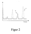
- FIG. 2 schematically shows two power spectra 21 and 22, as from the processing unit 5 from FIG. 1 be determined.
- the frequency spectrum 21 there are large amplitude fluctuations in the frequencies, indicating that the driver has no contact with the control input device. Only when the driver includes the control stick with his hand, resulting in a new overall system and thus a modified mechanism, also the power or frequency spectrum in the direction of the displayed spectrum 22, in which the frequencies have only low power changes. This is ultimately due to the fact that the damping properties were greatly changed by this so changed total mechanical system consisting of Steuerstick and the pilot, so that the frequencies are attenuated especially by the physiology of man. This can then be finally identified by the thus changed frequency spectrum.
- this method offers a secure possibility of recognizing the contact state between the control input device and the driver.
Abstract
Description
Die Erfindung betrifft ein Verfahren zur Detektion eines Kontaktszustandes zwischen mindestens einem Fahrzeugführer eines Fahrzeuges und einer zur Steuerung dieses Fahrzeuges eingerichteten Steuereingabevorrichtung. Die Erfindung betrifft auch eine Steuereingabevorrichtung hierzu.The invention relates to a method for detecting a contact state between at least one vehicle driver of a vehicle and a control input device configured to control this vehicle. The invention also relates to a control input device for this purpose.
Die momentan in der Entwicklung befindlichen aktiven Steuerorgane für Fahrzeuge, insbesondere für Luftfahrzeuge, auch aktive Sidesticks genannt, weisen gegenüber den herkömmlichen Steuerorganen den Vorteil auf, dass entsprechende Steuerkräfte künstlich durch Aktuatoren auf die Steuereingabevorrichtung aufgebracht werden können, um so dem Fahrzeugführer des Fahrzeuges ein reelleres Steuergefühl vermitteln zu können. Der Bediener beziehungsweise Fahrzeugführer bekommt somit das Gefühl, dass die Steuereingabevorrichtung tatsächlich mechanische Elemente, wie zum Beispiel Feder, Masse, Dämpfer oder Reibungsbremsen enthalten und mechanisch mit den Steuerungselementen des Fahrzeuges, wie beispielsweise Höhen oder Seitenruder, verbunden sind.The currently in development active control devices for vehicles, especially for aircraft, also called active sidesticks, have the advantage over the conventional control organs that appropriate control forces can be applied artificially by actuators on the control input device, so as to the driver of the vehicle a reelleres To convey control feeling. The operator or driver thus gets the feeling that the control input device actually contain mechanical elements, such as spring, mass, damper or friction brakes and are mechanically connected to the control elements of the vehicle, such as heights or rudder.
Solche aktiven Steuerorgane können aber auch dazu eingesetzt werden, dem Bediener beziehungsweise Fahrzeugführer taktile Hinweise zu übermitteln, um so einen weiteren Informationskanal zur Verfügung zu stellen. Solche derartigen taktilen Hinweise können dabei unterschiedlich dargestellt werden, etwa durch Vibration für ungerichtete Informationen oder durch lokale Kraftvariationen für gerichtete Informationen. Eine lokale Kraftvariation in Form eines sogenannten Softstops beispielsweise bewirkt, dass sich der Federkraftgradient ab einer bestimmten Position merklich vergrößert, so dass der Bediener beziehungsweise Fahrzeugführer auf haptischen Wege über das Erreichen eines beliebigen, vom Steuerweg abhängigen Limits informiert werden kann. Solche Hinweise werden auch "tactile cues" genannt. Die Entscheidung, einem solchen "tactile cue" zu folgen oder es zu übersteuern, bleibt dabei dem Bediener beziehungsweise Fahrzeugführer überlassen.However, such active control devices can also be used to transmit tactile information to the operator or vehicle driver so as to provide a further information channel. Such tactile indications can be represented differently, for example by vibration for undirected information or by local force variations for directed information. A local force variation in the form of a so-called soft stop, for example, causes the spring force gradient increased noticeably from a certain position, so that the operator or driver can be informed by haptic ways about reaching any, dependent on the control path limit. Such hints are also called "tactile cues". The decision to follow such a "tactile cue" or override it remains up to the operator or driver.
Ein großes Problem bei dieser Art der Informationsübertragung stellt dabei den Fakt dar, dass für eine Informationsübertragung auf diesem Informationskanal der Bediener beziehungsweise Fahrzeugführer mit der Steuereingabevorrichtung in Kontakt stehen muss, damit die taktilen Hinweise, die auf die Steuereingabevorrichtung aufgebracht werden, vom Fahrzeugführer wahrgenommen werden können. Erfolgt beispielsweise die Steuerung des Fahrzeuges mittels einer Hand-Steuereingabevorrichtung (Sidestick, Joystick), so muss der Fahrzeugführer die Steuereingabevorrichtung mit der Hand umfassen, um die Informationen wahrnehmen zu können. Würde er loslassen, würde das Steuer dem Kraftgradienten des "tactile cues", vom Fahrzeugführer unbemerkt, folgen, was wiederum dazu führt, dass das Fahrzeug der aufgebrachten Steuerbewegung folgt. Dabei sei darauf hingewiesen, dass die aufgebrachte Kraft auf das Steuerorgan keine eigentliche Steuerbewegung des Fahrzeuges darstellen soll, sondern lediglich dazu dienen soll, dem Fahrzeugführer eine Information zu übermitteln. Dass das Fahrzeug aufgrund des "tactile cues" eine Steuerbewegung vollzieht, würde der Fahrzeugführer erst dann bemerken, wenn die Bewegungsabweichung größer als seine Wahrnehmungsschwelle ist, was zu äußerst gefährlichen Situationen führen kann.A major problem with this type of information transmission is the fact that the operator or vehicle driver must be in contact with the control input device for information transmission on this information channel, so that the tactile information that is applied to the control input device can be perceived by the driver , For example, if the control of the vehicle by means of a hand-control input device (sidestick, joystick), the driver must enclose the control input device by hand in order to perceive the information. If he let go, the control would follow the force gradient of the "tactile cues" unnoticed by the driver, which in turn will cause the vehicle to follow the applied control movement. It should be noted that the force applied to the control body should not represent an actual control movement of the vehicle, but merely intended to convey information to the driver. The driver would only notice that the vehicle is making a control movement due to the "tactile cues" when the movement deviation is greater than its perception threshold, which can lead to extremely dangerous situations.
Es ist daher bei dieser Art von Steuereingabevorrichtungen von entscheidender Bedeutung, dass eine Information für den Fahrzeugführer erst dann auf das Steuerorgan beaufschlagt wird, wenn die Steuereingabevorrichtung sicher festgestellt hat, dass der Fahrzeugführer mit der Steuereingabevorrichtung des Fahrzeuges in Kontakt steht, beispielsweise mit der Hand umfasst.It is therefore of crucial importance in this type of control input device that information for the vehicle driver is not applied to the control element until the control input device has reliably ascertained that the driver is in contact with the control input device of the vehicle, for example by hand ,
Eine weitere Applikation, die das Detektieren eines Kontaktzustandes notwendig macht, ist die Stabilisierung der Steuereingabevorrichtung selbst. Denn die Steuereingabevorrichtung ist Beschleunigungen ausgesetzt, die beispielsweise aus der Erdbeschleunigung, der Bewegung des Luftfahrzeuges oder Vibrationen stammen. Die Steuersensorik der Steuereingabevorrichtung kann diese Trägheitskräfte nicht von den gewollten Kräften des Fahrzeugführers unterscheiden, wodurch es zu ungewollten Steuereingaben kommen kann. Eine Steuerkontakterkennung kann innerhalb der Regelung des Steuers dazu genutzt werden, dass es sich nur verstellen lässt, wenn sich eine Hand am Steuer befindet.Another application that requires the detection of a contact state, is the stabilization of the control input device itself. Because the control input device is exposed to accelerations, for example, from the gravitational acceleration, the movement of the aircraft or vibrations originate. The control sensor of the control input device can not distinguish these inertial forces from the intended forces of the driver, which can lead to unwanted control inputs. A control contact identifier can be used within the control of the control that it can only be adjusted when a hand is at the wheel.
Aus der
Des Weiteren ist aus der
Ein weiteres Verfahren, das sich auf die Analyse von Fahreraktivitäten bezieht, ist aus der
Die aus dem Stand der Technik bekannten Verfahren haben allesamt für den vorliegenden Aufgabenbereich den Nachteil, dass sie nicht mit hinreichender Genauigkeit einen tatsächlichen physischen Kontakt zwischen Steuereingabevorrichtung und Fahrzeugführer erkennen lassen, der jedoch insbesondere im Flugbetrieb notwendig ist. Ohne eine solche hinreichende genaue "Hands-on" Detektion lassen sich aktive Steuereingabevorrichtungen in Luftfahrzeugen nicht sicher betreiben.The methods known from the prior art all have the disadvantage for the present task, that they can not detect with sufficient accuracy an actual physical contact between the control input device and the driver, but which is particularly necessary in flight operations. Without such adequate "hands-on" detection, active control input devices in aircraft can not be safely operated.
Mit Blick auf das vorangegangene ist es daher Aufgabe der vorliegenden Erfindung, ein Verfahren anzugeben, das sicher einen Kontakt zwischen dem Fahrzeugführer und der für das Fahrzeug zur Steuerung vorgesehenen Steuereingabevorrichtung detektiert.In view of the foregoing, therefore, it is an object of the present invention to provide a method that securely detects contact between the vehicle driver and the control input device provided for the vehicle for control.
Die Aufgabe wird mit dem Verfahren der eingangs genannten Art erfindungsgemäß gelöst durch
- Ermitteln eines Frequenzspektrums anhand von Sensoren erfassten Bewegungssignalen der Steuereingabevorrichtung über die Zeit und
- Detektieren des Kontaktzustandes in Abhängigkeit des ermittelten Spektrums.
- Determining a frequency spectrum based on sensors detected motion signals of the control input device over time and
- Detecting the contact state as a function of the determined spectrum.
Die Steuereingabevorrichtung, wie beispielsweise ein Sidestick, weist dementsprechend Sensoren auf, welche die Bewegung des Steuerorgans detektieren. Diese Bewegungssignale werden in der Regel zur Steuerung des Fahrzeuges verwendet, wie dies beispielsweise im "fly-by-wire" Betrieb erfolgt. Dabei wurde erkannt, dass anhand des Frequenzspektrums dieser Bewegungssignale ermittelt werden kann, ob der Fahrzeugführer beziehungsweise Bediener physischen Kontakt mit der Steuereingabevorrichtung hält. Daher ermittelt die Steuereingabevorrichtung anhand dieser detektierten Bewegungssignale das entsprechende Frequenzspektrum, wobei anhand dieses Frequenzspektrums dann erkannt werden kann, ob der Fahrzeugführer mit der Steuereingabevorrichtung in Kontakt steht oder nicht.The control input device, such as a sidestick, accordingly has sensors which detect the movement of the control member. These motion signals are usually used to control the vehicle, as is done for example in "fly-by-wire" operation. It was recognized that it can be determined based on the frequency spectrum of these motion signals, whether the driver or operator holds physical contact with the control input device. Therefore, the control input device determines the corresponding frequency spectrum on the basis of these detected motion signals, it being possible to detect on the basis of this frequency spectrum whether the driver is in contact with the control input device or not.
Dem liegt das Prinzip zugrunde, dass der Bediener, wenn er die Steuereingabevorrichtung beispielsweise mit der Hand umfasst, das System des aktiven Steuers der Art verändert, dass sich ein neues mechanischen Gesamtsystem ergibt, da die Mechanik des Steuers zusammen mit der Masse der Hand und des Armes sowie der Elastizität der Haut und des Gewebes, der Muskeln und der Gelenke das Gesamtsystem verändert. Aufgrund dieses neuen mechanischen Gesamtsystems verändert sich auch das Schwingungsverhalten naturgemäß, so dass sich die Frequenzspektren des ungegriffenen Steuers mit dem des gegriffenen Steuers charakteristisch unterscheiden, worauf sicher auf einen Kontakt zwischen Hand und Steuer geschlossen werden kann. Der Unterschied zwischen "hands-on" und "hands off" ist in den Spektren der gemessenen Sensorsignale sichtbar.This is based on the principle that the operator, if he includes the control input device, for example by hand, changes the system of the active control of the type that results in a new overall mechanical system, since the mechanics of the control together with the mass of the hand and the Poor as well as the elasticity of the skin and the tissue, the muscles and the joints changed the whole system. Due to this new overall mechanical system, the vibration behavior naturally changes, so that the frequency spectra of the unencumbered control with the gripped control characteristic differ, which can be safely concluded that a contact between the hand and the control. The difference between "hands-on" and "hands off" is visible in the spectra of the measured sensor signals.
Bei den Sensoren kann es sich dabei um sogenannte Stellungssensoren handeln, welche die Bewegungssignale der Steuereingabevorrichtung über die Zeit erfassen. Solche Stellungssensoren können insbesondere Winkel- und/oder Positionssensoren sein, aber auch Kraftsensoren sein, welche den entsprechenden aufgebrachten Kraftgradienten des Bedieners ermitteln. Auch Beschleunigungssensoren können dabei zum Einsatz kommen.The sensors may be so-called position sensors which detect the motion signals of the control input device over time. Such position sensors may in particular be angular and / or position sensors, but also be force sensors which determine the corresponding applied force gradients of the operator. Also acceleration sensors can be used.
Ganz besonders vorteilhaft ist es, wenn aus dem ermittelten Frequenzbereich der Bewegungssignale bestimmte Frequenzbereich gefiltert wird, und nur anhand der gefilterten Frequenzbereiche eine "hands-on" Detektion erfolgt. So wurde beispielsweise erkannt, dass in höheren Frequenzbereichen charakteristische Vibrationen erkennbar sind, die sich aus Vibrationen aus der Umgebung des Steuers zusammensetzen. Wird das Steuer nun von dem Fahrzeugführer gegriffen, so verändern sich diese Frequenzen entsprechend, was dann detektierbar ist.It is particularly advantageous if certain frequency ranges are filtered out of the determined frequency range of the motion signals, and a "hands-on" detection takes place only on the basis of the filtered frequency ranges. It has been recognized, for example, that in higher frequency ranges characteristic vibrations can be seen, which are composed of vibrations from the environment of the control. If the control is now seized by the driver, then these frequencies change accordingly, which is then detectable.
Vorteilhafterweise kann die Detektion anhand eines Vergleiches zwischen einem ermittelten Referenz-Frequenzspektrums mit dem ermittelten Frequenzspektrum erfolgen. Dies ist deshalb besonders vorteilhaft, da sich das Frequenzspektrum, welches sich ergibt, wenn der Fahrer die Hand nicht am Steuer hat, von Fahrzeug zu Fahrzeug aufgrund des unterschiedlichen Fahrzeugaufbaus von Fahrzeug zu Fahrzeug unterscheiden.Advantageously, the detection based on a comparison between a determined reference frequency spectrum with the determined frequency spectrum respectively. This is particularly advantageous because the frequency spectrum, which results when the driver does not have his hand at the wheel, differ from vehicle to vehicle due to the different vehicle structure from vehicle to vehicle.
Ganz besonders vorteilhaft ist es, wenn Vibrationen in der Umgebung der Steuereingabevorrichtung mittels Sensoren erfasst werden und zu Detektion des Kontaktzustands anhand des ermittelten Frequenzspektrums herangezogen werden. Diese Vibrationen in der Umgebung der Steuereingabevorrichtung ergeben sich aus der Bewegung des Fahrzeuges selbst, wie beispielsweise eines Hubschraubers, der stark vibriert. Umfasst der Fahrzeugführer das Steuer nicht, so werden diese Vibrationen auf das Steuer ungewollt übertragen, was sich anhand der Sensoren detektieren lässt. In dem ermittelten Frequenzspektrum finden sich dann diese Vibrationen nahezu identisch wieder. Umfasst der Fahrzeugführer jedoch das Steuer, so wird aufgrund des neuen mechanischen Gesamtsystems und der veränderten Dämpfungseigenschaften diese Vibration zum Teil geschluckt, so dass sich anhand dieser Veränderung ein Kontaktzustand detektieren lässt.It is particularly advantageous if vibrations in the surroundings of the control input device are detected by means of sensors and are used to detect the contact state on the basis of the determined frequency spectrum. These vibrations in the vicinity of the control input device result from the movement of the vehicle itself, such as a helicopter, which vibrates strongly. If the driver does not include the control, these vibrations are transmitted unintentionally to the control, which can be detected by the sensors. In the determined frequency spectrum, these vibrations are then found almost identically. However, if the driver includes the control, due to the new overall mechanical system and the modified damping properties, this vibration is partly swallowed, so that a contact state can be detected based on this change.
Des Weiteren wurde erkannt, dass aufgrund der Veränderung des Frequenzspektrums sich auch die Griffstärke erkennen lässt, da mit zunehmender Griffstärke sich auch das Frequenzspektrum verändert. Es ist daher ganz besonders vorteilhaft, wenn anhand des ermittelten Frequenzspektrums auch zusätzlich die Griffstärke bei einem Hand-Steuerkontakt erkennen lässt.Furthermore, it was recognized that due to the change in the frequency spectrum, the grip strength can be seen, since with increasing grip strength and the frequency spectrum changes. It is therefore particularly advantageous if, on the basis of the determined frequency spectrum, the grip strength can also be recognized additionally in the case of a manual control contact.
Darüber hinaus wird die Aufgabe auch mit einer Steuereingabevorrichtung zur Steuerung eines Fahrzeuges gelöst. Die Steuereingabevorrichtung enthält Sensoren zur Erfassung von Bewegungssignalen der Steuereingabevorrichtung, wobei mit Hilfe einer Recheneinheit aus den erfassten Bewegungssignalen das Frequenzspektrum ermittelt wird, woraus sich dann der Kontaktzustand in Abhängigkeit des ermittelten Frequenzspektrums ermitteln lässt.In addition, the object is also achieved with a control input device for controlling a vehicle. The control input device contains sensors for detecting motion signals of the control input device, the frequency spectrum being determined with the aid of a computing unit from the detected motion signals, from which the contact state can then be determined as a function of the determined frequency spectrum.
Die vorliegende Erfindung wird anhand der beigefügten Zeichnungen beispielhaft näher erläutert. Es zeigen:
Figur 1- - schematische Darstellung einer Steuereingabevorrichtung basierend auf dem erfindungsgemäßen Verfahren;
Figur 2- - schematische Darstellung zweier Frequenzspektren.
- FIG. 1
- - Schematic representation of a control input device based on the method according to the invention;
- FIG. 2
- - Schematic representation of two frequency spectra.
In der Mechanik 3 befinden sich entsprechende Sensoren 4a, 4b, welche die Bewegungssignale in den Schwenkrichtungen R1 und R2 sehr genau ermitteln. Die Sensoren 4a, 4b können dabei beispielsweise Winkel- oder Positionssensoren sein, welche einen bestimmten Ausschlag des Steuersticks 2 in eine der Schwenkrichtungen R1 oder R2 detektieren. Die von den Sensoren 4a, 4b ermittelten Bewegungssignale werden dann an eine Verarbeitungseinheit 5 weitergeleitet, die dann aus den ermittelten Bewegungssignalen das Frequenzspektrum ermittelt, anhand dessen dann der Kontaktzustand ermittelt wird. Diese Analyse des Frequenzspektrums kann ebenfalls in der Verarbeitungseinheit 5 erfolgen.In the
Wie bereits oben erwähnt, verändert sich durch den Kontakt des Fahrzeugführers mit der Steuereingabevorrichtung 1 das Frequenzspektrum, so dass aufgrund dieser Analyse in der Verarbeitungseinheit 5 entsprechend sicher festgestellt werden kann, ob der Fahrzeugführer mit der Steuereingabevorrichtung 1 in Kontakt steht.As already mentioned above, the frequency spectrum changes as a result of the vehicle driver's contact with the
Solch eine Steuereingabevorrichtung kann beispielsweise zur Steuerung eines Hubschraubers eingesetzt werden, bei dem mit Hilfe des aktiven Sidesticks 2 die Steuerung der kollektiven Blattanstellwinkel durchgefügt wird. Über die kollektiven Blattwinkelverstellungen wird, in Abhängigkeit vom Flugzustand, die Leistung des Hubschraubers gesteuert. Auf der Basis des aktiven Sidesticks 2 kann dann eine taktile Funktion zur Einhaltung des Leistungslimits implementiert werden, um so dem Piloten einen weiteren Informationskanal zwischen der Mensch-Maschine-Schnittstelle zur Verfügung zu stellen. Wenn das Limit erreicht wird, generiert der aktive Sidestick eine Kraft nach unten, das heißt in Richtung geringerer Leistung, bis die aktuell kommandierte Leistung geringer als die zulässige Leistung ist. Der Pilot spürt diese Kraft am Steuer und folgt ihr.Such a control input device can be used, for example, for controlling a helicopter in which the control of the collective blade pitch is performed by means of the
Angenommen, der Pilot nimmt seine Hand vom Steuer, während sich der Hubschrauber in einem Flugzustand nahe des Leistungslimits befindet, so dass ihm der taktile Informationskanal nicht zur Verfügung steht. Wenn es in dieser Situation aufgrund äußerer Störungen dazu kommt, dass sich die Momentanleistung erhöht, dann würden die taktilen Funktionen eine Kraft erzeugen, die versuchen, das Steuer nach unten zu bewegen. Da der Pilot seine Hand nicht am Steuer hat, kann er dies zum einen nicht verhindern und zum anderen merkt er dies erst dann, wenn der Hubschrauber auf die ungewollte Steuereingabe reagiert. Der Pilot ist "out-off-the-loop", was je nach Flugsituation sehr gefährlich werden kann. Durch die Detektion des Handkontaktes zwischen der Steuereingabevorrichtung und des Piloten kann dies verhindert werden, so dass der Pilot das volle Situationsbewusstsein behält.Suppose the pilot takes his hand off the steering wheel while the helicopter is in a flight condition near the power limit, so the tactile information channel is unavailable. In this situation, if external noise causes the instantaneous power to increase, then the tactile functions would create a force trying to move the control down. Since the pilot does not have his hand at the wheel, he can not prevent this on the one hand and on the other he only notices this when the helicopter responds to the unwanted control input. The pilot is "out-of-the-loop", which can be very dangerous depending on the flight situation. By detecting the hand contact between the control input device and the pilot, this can be prevented so that the pilot retains full situational awareness.
Ein großer Vorteil bei diesem Verfahren liegt insbesondere auch darin, dass dieses Verfahren in nahezu allen Steuerelementen nachgerüstet werden kann, die mit solchen Bewegungssensoren ausgerüstet sind. Es kann somit auf die bereits vorhandenen Sensoren zurückgegriffen werden, ohne teure und aufwendige Umbaumaßnahmen durchführen zu müssen. Des Weiteren bietet dieses Verfahren aufgrund der unverkennbaren Charakteristik der Frequenzspektren eine sichere Möglichkeit, den Kontaktzustand zwischen Steuereingabevorrichtung und dem Fahrzeugführer zu erkennen.A major advantage of this method is in particular that this method can be retrofitted in almost all controls that are equipped with such motion sensors. It can thus be used on the existing sensors without having to carry out expensive and expensive conversion measures. Furthermore, due to the unmistakable characteristics of the frequency spectrums, this method offers a secure possibility of recognizing the contact state between the control input device and the driver.
Claims (10)
Applications Claiming Priority (1)
| Application Number | Priority Date | Filing Date | Title |
|---|---|---|---|
| DE102010019236.8A DE102010019236B4 (en) | 2010-05-03 | 2010-05-03 | Contact recognition |
Publications (2)
| Publication Number | Publication Date |
|---|---|
| EP2384946A2 true EP2384946A2 (en) | 2011-11-09 |
| EP2384946A3 EP2384946A3 (en) | 2013-03-27 |
Family
ID=44280647
Family Applications (1)
| Application Number | Title | Priority Date | Filing Date |
|---|---|---|---|
| EP11003114A Withdrawn EP2384946A3 (en) | 2010-05-03 | 2011-04-13 | Contact detection between user and control device |
Country Status (3)
| Country | Link |
|---|---|
| US (1) | US8887570B2 (en) |
| EP (1) | EP2384946A3 (en) |
| DE (1) | DE102010019236B4 (en) |
Cited By (40)
| Publication number | Priority date | Publication date | Assignee | Title |
|---|---|---|---|---|
| CN103158699A (en) * | 2011-12-15 | 2013-06-19 | 操纵技术Ip控股公司 | Hands on steering wheel detect in lane centering operation |
| US9809155B2 (en) | 2015-10-27 | 2017-11-07 | Steering Solutions Ip Holding Corporation | Retractable steering column assembly having lever, vehicle having retractable steering column assembly, and method |
| US9828016B2 (en) | 2015-06-24 | 2017-11-28 | Steering Solutions Ip Holding Corporation | Retractable steering column system, vehicle having the same, and method |
| US9840271B2 (en) | 2015-06-29 | 2017-12-12 | Steering Solutions Ip Holding Corporation | Retractable steering column with rake limiter |
| US9845106B2 (en) | 2015-08-31 | 2017-12-19 | Steering Solutions Ip Holding Corporation | Overload protection for belt drive mechanism |
| US9849904B2 (en) | 2015-07-31 | 2017-12-26 | Steering Solutions Ip Holding Corporation | Retractable steering column with dual actuators |
| US9862403B1 (en) | 2016-11-29 | 2018-01-09 | Steering Solutions Ip Holding Corporation | Manually retractable steering column assembly for autonomous vehicle |
| US9919724B2 (en) | 2015-05-29 | 2018-03-20 | Steering Solutions Ip Holding Corporation | Retractable steering column with manual retrieval |
| US10029725B2 (en) | 2015-12-03 | 2018-07-24 | Steering Solutions Ip Holding Corporation | Torque feedback system for a steer-by-wire vehicle, vehicle having steering column, and method of providing feedback in vehicle |
| US10029676B2 (en) | 2014-01-29 | 2018-07-24 | Steering Solutions Ip Holding Corporation | Hands on steering wheel detect |
| US10112639B2 (en) | 2015-06-26 | 2018-10-30 | Steering Solutions Ip Holding Corporation | Vehicle steering arrangement and method of making same |
| US10160477B2 (en) | 2016-08-01 | 2018-12-25 | Steering Solutions Ip Holding Corporation | Electric power steering column assembly |
| US10160473B2 (en) | 2016-09-13 | 2018-12-25 | Steering Solutions Ip Holding Corporation | Steering column decoupling system |
| US10160472B2 (en) | 2015-10-20 | 2018-12-25 | Steering Solutions Ip Holding Corporation | Steering column with stationary hub |
| US10189496B2 (en) | 2016-08-22 | 2019-01-29 | Steering Solutions Ip Holding Corporation | Steering assembly having a telescope drive lock assembly |
| WO2019025281A1 (en) * | 2017-08-03 | 2019-02-07 | Trw Automotive Gmbh | Method for detecting a driver's hands on a steering wheel of a vehicle |
| US10239552B2 (en) | 2016-10-14 | 2019-03-26 | Steering Solutions Ip Holding Corporation | Rotation control assembly for a steering column |
| US10310605B2 (en) | 2016-11-15 | 2019-06-04 | Steering Solutions Ip Holding Corporation | Haptic feedback for steering system controls |
| US10343706B2 (en) | 2015-06-11 | 2019-07-09 | Steering Solutions Ip Holding Corporation | Retractable steering column system, vehicle having the same, and method |
| US10351161B2 (en) | 2016-05-27 | 2019-07-16 | Steering Solutions Ip Holding Corporation | Steering column with manual retraction |
| US10351160B2 (en) | 2016-11-30 | 2019-07-16 | Steering Solutions Ip Holding Corporation | Steering column assembly having a sensor assembly |
| US10351159B2 (en) | 2015-05-01 | 2019-07-16 | Steering Solutions Ip Holding Corporation | Retractable steering column with a radially projecting attachment |
| US10363958B2 (en) | 2016-07-26 | 2019-07-30 | Steering Solutions Ip Holding Corporation | Electric power steering mode determination and transitioning |
| US10370022B2 (en) | 2017-02-13 | 2019-08-06 | Steering Solutions Ip Holding Corporation | Steering column assembly for autonomous vehicle |
| US10384708B2 (en) | 2016-09-12 | 2019-08-20 | Steering Solutions Ip Holding Corporation | Intermediate shaft assembly for steer-by-wire steering system |
| US10385930B2 (en) | 2017-02-21 | 2019-08-20 | Steering Solutions Ip Holding Corporation | Ball coupling assembly for steering column assembly |
| US10399591B2 (en) | 2016-10-03 | 2019-09-03 | Steering Solutions Ip Holding Corporation | Steering compensation with grip sensing |
| US10421475B2 (en) | 2016-11-15 | 2019-09-24 | Steering Solutions Ip Holding Corporation | Electric actuator mechanism for retractable steering column assembly with manual override |
| US10421476B2 (en) | 2016-06-21 | 2019-09-24 | Steering Solutions Ip Holding Corporation | Self-locking telescope actuator of a steering column assembly |
| US10436299B2 (en) | 2015-06-25 | 2019-10-08 | Steering Solutions Ip Holding Corporation | Stationary steering wheel assembly and method |
| US10442441B2 (en) | 2015-06-15 | 2019-10-15 | Steering Solutions Ip Holding Corporation | Retractable handwheel gesture control |
| US10449927B2 (en) | 2017-04-13 | 2019-10-22 | Steering Solutions Ip Holding Corporation | Steering system having anti-theft capabilities |
| US10457313B2 (en) | 2016-06-28 | 2019-10-29 | Steering Solutions Ip Holding Corporation | ADAS wheel locking device |
| US10481602B2 (en) | 2016-10-17 | 2019-11-19 | Steering Solutions Ip Holding Corporation | Sensor fusion for autonomous driving transition control |
| US10562561B2 (en) | 2016-04-25 | 2020-02-18 | Steering Solutions Ip Holding Corporation | Electrical power steering control using system state predictions |
| US10577009B2 (en) | 2015-06-16 | 2020-03-03 | Steering Solutions Ip Holding Corporation | Retractable steering column assembly and method |
| US10589774B2 (en) | 2015-05-01 | 2020-03-17 | Steering Solutions Ip Holding Corporation | Counter rotation steering wheel |
| US10766518B2 (en) | 2015-06-25 | 2020-09-08 | Steering Solutions Ip Holding Corporation | Rotation control system for a steering wheel and method |
| US10875566B2 (en) | 2018-03-22 | 2020-12-29 | Steering Solutions Ip Holding Corporation | Stow release assembly for a manually adjustable steering column assembly |
| US11560169B2 (en) | 2015-06-11 | 2023-01-24 | Steering Solutions Ip Holding Corporation | Retractable steering column system and method |
Families Citing this family (10)
| Publication number | Priority date | Publication date | Assignee | Title |
|---|---|---|---|---|
| US9481375B2 (en) * | 2010-12-03 | 2016-11-01 | Pedal Logic Lp | Method and apparatus to adjust for undesired force influencing a vehicle input control |
| US9387861B1 (en) | 2010-12-03 | 2016-07-12 | Pedal Logic Lp | System, method, and apparatus for optimizing acceleration in a vehicle |
| US9604649B1 (en) | 2016-02-12 | 2017-03-28 | GM Global Technology Operations LLC | Hands-off detection enhancement by means of a synthetic signal |
| US10496102B2 (en) | 2016-04-11 | 2019-12-03 | Steering Solutions Ip Holding Corporation | Steering system for autonomous vehicle |
| DE102016005013A1 (en) | 2016-04-26 | 2017-10-26 | Thyssenkrupp Ag | Hands-on / off detection in a steer-by-wire system |
| SE541322C2 (en) | 2016-06-02 | 2019-07-02 | Scania Cv Ab | Method and system for determining whether the driver of a vehicle is holding the steering wheel |
| US10780915B2 (en) | 2016-12-07 | 2020-09-22 | Steering Solutions Ip Holding Corporation | Vehicle steering system having a user experience based automated driving to manual driving transition system and method |
| US10023138B1 (en) | 2017-01-17 | 2018-07-17 | Pedal Logic Lp | Power connection for a vehicular acceleration input control apparatus |
| US10974756B2 (en) | 2018-07-31 | 2021-04-13 | Steering Solutions Ip Holding Corporation | Clutch device latching system and method |
| KR20230012718A (en) * | 2021-07-16 | 2023-01-26 | 삼성전자주식회사 | Electronic Device and Method for Generating Speech Signal |
Citations (3)
| Publication number | Priority date | Publication date | Assignee | Title |
|---|---|---|---|---|
| DE10358494A1 (en) | 2003-12-13 | 2005-07-07 | Daimlerchrysler Ag | Vehicle driver control assistance program, to correct dangerous maneuvers, prepares redundance strategy data from given strategy data for spectral analysis |
| DE102007039332A1 (en) | 2006-08-24 | 2008-02-28 | Continental Teves Ag & Co. Ohg | Driver`s hand contact condition detecting method for use in vehicle, involves evaluating driver steering moment using condition observer, and detecting contact condition between hands and handle by hand-off detector using evaluated moment |
| DE102008021150A1 (en) | 2008-02-25 | 2009-08-27 | Volkswagen Ag | Method for identification of missing driver activity at steering wheel of motor vehicle, involves determining hand moment of driver exerted at steering wheel |
Family Cites Families (18)
| Publication number | Priority date | Publication date | Assignee | Title |
|---|---|---|---|---|
| US3970840A (en) * | 1974-07-16 | 1976-07-20 | Lear Siegler, Inc. | Control circuitry for vehicle guidance mechanism |
| US4024651A (en) * | 1976-04-27 | 1977-05-24 | The United States Of America As Represented By The Secretary Of The Navy | Variable feel side stick controller |
| SE8800848D0 (en) * | 1988-03-10 | 1988-03-10 | Saab Scania Ab | SETTING AND DEVICE FOR MONITORING A STEERING OFFICE OF A VEHICLE DRIVER |
| US5149023A (en) * | 1991-07-12 | 1992-09-22 | The Boeing Company | Mechanically-linked side stick controllers with isolated pitch and roll control movement |
| JP3070384B2 (en) * | 1994-04-26 | 2000-07-31 | 三菱自動車工業株式会社 | Driving attention discrimination method |
| DE19713245C2 (en) * | 1997-03-29 | 2001-02-15 | Mercedes Benz Lenkungen Gmbh | Motor vehicle with at least one part controllable via at least one control lever in the form of a so-called side stick |
| US5798695A (en) * | 1997-04-02 | 1998-08-25 | Northrop Grumman Corporation | Impaired operator detection and warning system employing analysis of operator control actions |
| US6678567B1 (en) * | 2000-06-29 | 2004-01-13 | Rockwell Collins, Inc. | Pilot input device to control direction, altitude, and speed of aircraft |
| US6625530B1 (en) * | 2000-11-06 | 2003-09-23 | Delphi Technologies, Inc. | Feed forward—feed back control for steer-by-wire system |
| DE10155083A1 (en) * | 2001-02-19 | 2002-09-12 | Bosch Gmbh Robert | Method for detecting contact between a user and an operating element on a machine, picks up vibrational properties in the operating element which changes upon contact with a user in order to compare them with preset vibrational properties |
| US6374163B1 (en) * | 2001-03-30 | 2002-04-16 | Continental Teves, Inc. | Online frequency analysis for resource optimized systems |
| US6644600B1 (en) * | 2002-04-25 | 2003-11-11 | Rockwell Collins, Inc. | Method and system for providing manipulation restraining forces for a stick controller on an aircraft |
| US6895357B2 (en) * | 2002-09-30 | 2005-05-17 | Continental Teves, Inc. | Offset calibration of a semi-relative steering wheel angle sensor |
| US7513456B2 (en) * | 2005-05-13 | 2009-04-07 | The Boeing Company | Apparatus and method for reduced backlash steering tiller |
| DE102005056438A1 (en) * | 2005-11-26 | 2007-06-14 | Volkswagen Ag | Method and device for steering wheel monitoring |
| US7658349B2 (en) * | 2006-10-26 | 2010-02-09 | Honeywell International Inc. | Pilot flight control stick haptic feedback system and method |
| US7759894B2 (en) * | 2006-10-26 | 2010-07-20 | Honeywell International Inc. | Cogless motor driven active user interface haptic feedback system |
| DE102008033722A1 (en) * | 2008-07-15 | 2010-01-28 | Volkswagen Ag | Method and apparatus for driver presence detection |
-
2010
- 2010-05-03 DE DE102010019236.8A patent/DE102010019236B4/en not_active Expired - Fee Related
-
2011
- 2011-04-13 EP EP11003114A patent/EP2384946A3/en not_active Withdrawn
- 2011-05-02 US US13/098,513 patent/US8887570B2/en not_active Expired - Fee Related
Patent Citations (3)
| Publication number | Priority date | Publication date | Assignee | Title |
|---|---|---|---|---|
| DE10358494A1 (en) | 2003-12-13 | 2005-07-07 | Daimlerchrysler Ag | Vehicle driver control assistance program, to correct dangerous maneuvers, prepares redundance strategy data from given strategy data for spectral analysis |
| DE102007039332A1 (en) | 2006-08-24 | 2008-02-28 | Continental Teves Ag & Co. Ohg | Driver`s hand contact condition detecting method for use in vehicle, involves evaluating driver steering moment using condition observer, and detecting contact condition between hands and handle by hand-off detector using evaluated moment |
| DE102008021150A1 (en) | 2008-02-25 | 2009-08-27 | Volkswagen Ag | Method for identification of missing driver activity at steering wheel of motor vehicle, involves determining hand moment of driver exerted at steering wheel |
Cited By (44)
| Publication number | Priority date | Publication date | Assignee | Title |
|---|---|---|---|---|
| CN103158699A (en) * | 2011-12-15 | 2013-06-19 | 操纵技术Ip控股公司 | Hands on steering wheel detect in lane centering operation |
| EP2604487A1 (en) * | 2011-12-15 | 2013-06-19 | Steering Solutions IP Holding Corporation | Hands on steering wheel detect in lane centering operation |
| US8548667B2 (en) | 2011-12-15 | 2013-10-01 | Steering Solutions Ip Holding Corporation | Hands on steering wheel detect in lane centering operation |
| CN103158699B (en) * | 2011-12-15 | 2016-03-16 | 操纵技术Ip控股公司 | Hand detection on the steering wheel in lane centering operation |
| US10029676B2 (en) | 2014-01-29 | 2018-07-24 | Steering Solutions Ip Holding Corporation | Hands on steering wheel detect |
| US10351159B2 (en) | 2015-05-01 | 2019-07-16 | Steering Solutions Ip Holding Corporation | Retractable steering column with a radially projecting attachment |
| US10589774B2 (en) | 2015-05-01 | 2020-03-17 | Steering Solutions Ip Holding Corporation | Counter rotation steering wheel |
| US9919724B2 (en) | 2015-05-29 | 2018-03-20 | Steering Solutions Ip Holding Corporation | Retractable steering column with manual retrieval |
| US11560169B2 (en) | 2015-06-11 | 2023-01-24 | Steering Solutions Ip Holding Corporation | Retractable steering column system and method |
| US10343706B2 (en) | 2015-06-11 | 2019-07-09 | Steering Solutions Ip Holding Corporation | Retractable steering column system, vehicle having the same, and method |
| US10442441B2 (en) | 2015-06-15 | 2019-10-15 | Steering Solutions Ip Holding Corporation | Retractable handwheel gesture control |
| US10577009B2 (en) | 2015-06-16 | 2020-03-03 | Steering Solutions Ip Holding Corporation | Retractable steering column assembly and method |
| US9828016B2 (en) | 2015-06-24 | 2017-11-28 | Steering Solutions Ip Holding Corporation | Retractable steering column system, vehicle having the same, and method |
| US10766518B2 (en) | 2015-06-25 | 2020-09-08 | Steering Solutions Ip Holding Corporation | Rotation control system for a steering wheel and method |
| US10436299B2 (en) | 2015-06-25 | 2019-10-08 | Steering Solutions Ip Holding Corporation | Stationary steering wheel assembly and method |
| US10112639B2 (en) | 2015-06-26 | 2018-10-30 | Steering Solutions Ip Holding Corporation | Vehicle steering arrangement and method of making same |
| US9840271B2 (en) | 2015-06-29 | 2017-12-12 | Steering Solutions Ip Holding Corporation | Retractable steering column with rake limiter |
| US9849904B2 (en) | 2015-07-31 | 2017-12-26 | Steering Solutions Ip Holding Corporation | Retractable steering column with dual actuators |
| US9845106B2 (en) | 2015-08-31 | 2017-12-19 | Steering Solutions Ip Holding Corporation | Overload protection for belt drive mechanism |
| US10160472B2 (en) | 2015-10-20 | 2018-12-25 | Steering Solutions Ip Holding Corporation | Steering column with stationary hub |
| US9809155B2 (en) | 2015-10-27 | 2017-11-07 | Steering Solutions Ip Holding Corporation | Retractable steering column assembly having lever, vehicle having retractable steering column assembly, and method |
| US10029725B2 (en) | 2015-12-03 | 2018-07-24 | Steering Solutions Ip Holding Corporation | Torque feedback system for a steer-by-wire vehicle, vehicle having steering column, and method of providing feedback in vehicle |
| US10562561B2 (en) | 2016-04-25 | 2020-02-18 | Steering Solutions Ip Holding Corporation | Electrical power steering control using system state predictions |
| US10351161B2 (en) | 2016-05-27 | 2019-07-16 | Steering Solutions Ip Holding Corporation | Steering column with manual retraction |
| US10421476B2 (en) | 2016-06-21 | 2019-09-24 | Steering Solutions Ip Holding Corporation | Self-locking telescope actuator of a steering column assembly |
| US10457313B2 (en) | 2016-06-28 | 2019-10-29 | Steering Solutions Ip Holding Corporation | ADAS wheel locking device |
| US10363958B2 (en) | 2016-07-26 | 2019-07-30 | Steering Solutions Ip Holding Corporation | Electric power steering mode determination and transitioning |
| US10160477B2 (en) | 2016-08-01 | 2018-12-25 | Steering Solutions Ip Holding Corporation | Electric power steering column assembly |
| US10189496B2 (en) | 2016-08-22 | 2019-01-29 | Steering Solutions Ip Holding Corporation | Steering assembly having a telescope drive lock assembly |
| US10384708B2 (en) | 2016-09-12 | 2019-08-20 | Steering Solutions Ip Holding Corporation | Intermediate shaft assembly for steer-by-wire steering system |
| US10160473B2 (en) | 2016-09-13 | 2018-12-25 | Steering Solutions Ip Holding Corporation | Steering column decoupling system |
| US10399591B2 (en) | 2016-10-03 | 2019-09-03 | Steering Solutions Ip Holding Corporation | Steering compensation with grip sensing |
| US10239552B2 (en) | 2016-10-14 | 2019-03-26 | Steering Solutions Ip Holding Corporation | Rotation control assembly for a steering column |
| US10481602B2 (en) | 2016-10-17 | 2019-11-19 | Steering Solutions Ip Holding Corporation | Sensor fusion for autonomous driving transition control |
| US10421475B2 (en) | 2016-11-15 | 2019-09-24 | Steering Solutions Ip Holding Corporation | Electric actuator mechanism for retractable steering column assembly with manual override |
| US10310605B2 (en) | 2016-11-15 | 2019-06-04 | Steering Solutions Ip Holding Corporation | Haptic feedback for steering system controls |
| US9862403B1 (en) | 2016-11-29 | 2018-01-09 | Steering Solutions Ip Holding Corporation | Manually retractable steering column assembly for autonomous vehicle |
| US10351160B2 (en) | 2016-11-30 | 2019-07-16 | Steering Solutions Ip Holding Corporation | Steering column assembly having a sensor assembly |
| US10370022B2 (en) | 2017-02-13 | 2019-08-06 | Steering Solutions Ip Holding Corporation | Steering column assembly for autonomous vehicle |
| US10385930B2 (en) | 2017-02-21 | 2019-08-20 | Steering Solutions Ip Holding Corporation | Ball coupling assembly for steering column assembly |
| US10449927B2 (en) | 2017-04-13 | 2019-10-22 | Steering Solutions Ip Holding Corporation | Steering system having anti-theft capabilities |
| WO2019025281A1 (en) * | 2017-08-03 | 2019-02-07 | Trw Automotive Gmbh | Method for detecting a driver's hands on a steering wheel of a vehicle |
| US11173836B2 (en) | 2017-08-03 | 2021-11-16 | Zf Automotive Germany Gmbh | Method for detecting a driver's hands on a steering wheel of a vehicle |
| US10875566B2 (en) | 2018-03-22 | 2020-12-29 | Steering Solutions Ip Holding Corporation | Stow release assembly for a manually adjustable steering column assembly |
Also Published As
| Publication number | Publication date |
|---|---|
| US20110266396A1 (en) | 2011-11-03 |
| EP2384946A3 (en) | 2013-03-27 |
| DE102010019236A1 (en) | 2011-11-03 |
| US8887570B2 (en) | 2014-11-18 |
| DE102010019236B4 (en) | 2014-07-17 |
Similar Documents
| Publication | Publication Date | Title |
|---|---|---|
| DE102010019236B4 (en) | Contact recognition | |
| DE102018210320A1 (en) | Driving system with an automated lateral guidance that can be deactivated by steering intervention, and a method for deactivating an automated lateral guidance | |
| EP3448740A1 (en) | Hands-on/-off detection in a steer-by-wire system | |
| WO2013117309A1 (en) | Motor vehicle comprising a driver assistance device and method for operating a motor vehicle | |
| WO2020212147A1 (en) | Method for determining a trajectory of a robot | |
| EP3494021B1 (en) | Method for adapting a man-machine interface in a motor vehicle, and motor vehicle | |
| DE102010035825A1 (en) | Control system and apparatus for generating a virtual real-time model | |
| DE102011054848A1 (en) | Control and monitoring device for vehicles | |
| DE102018205753A1 (en) | Method, device and means of transport for an automated approach of a means of locomotion to a traffic signal system | |
| WO2020048754A1 (en) | Steering column module for a steer-by-wire steering system of a vehicle | |
| WO2022214452A1 (en) | Method for generating a control signal for a lateral control device of a motor vehicle operated in an at least partially assisted manner, and assistance system | |
| DE102011101541A1 (en) | Control unit for driver assistance system for setting functions for motion control of motor car, has evaluation unit detecting one of positions, and input for manual change of actual speed entered in respective position of process | |
| DE102009027979B4 (en) | A method and apparatus for providing a pilot alert signal to a pilot of an aircraft | |
| DE102015005124A1 (en) | A method of controlling a steering actuator of a steering system of a vehicle, steering system and vehicle having such a steering system | |
| DE102015204365A1 (en) | Device and method for autonomous or semi-autonomous control of a vehicle | |
| DE102012106233A1 (en) | Method for representing oscillating motion of oscillation capable load, involves detecting oscillation deflection of oscillating motion of oscillation capable load with respect to vertical axis of support system | |
| DE102010022200A1 (en) | Joystick System | |
| WO2015120984A1 (en) | Motor vehicle | |
| DE102015118030B4 (en) | Autopilot for atmospheric aircraft and aircraft and speed control method for this purpose | |
| DE102014019243B4 (en) | Method for operating an operating device of a vehicle, in particular a motor vehicle | |
| DE102012112894B4 (en) | Rotor aircraft with a feedback control device for generating control commands | |
| EP2591976B1 (en) | Steering device for a motor vehicle | |
| EP3217378B1 (en) | Method and device for guiding traffic, in particular aircraft | |
| DE102016001362B4 (en) | Drift assistance system for a motor vehicle | |
| DE102019005180A1 (en) | Procedure for displaying system boundaries |
Legal Events
| Date | Code | Title | Description |
|---|---|---|---|
| AK | Designated contracting states |
Kind code of ref document: A2 Designated state(s): AL AT BE BG CH CY CZ DE DK EE ES FI FR GB GR HR HU IE IS IT LI LT LU LV MC MK MT NL NO PL PT RO RS SE SI SK SM TR |
|
| AX | Request for extension of the european patent |
Extension state: BA ME |
|
| PUAI | Public reference made under article 153(3) epc to a published international application that has entered the european phase |
Free format text: ORIGINAL CODE: 0009012 |
|
| PUAL | Search report despatched |
Free format text: ORIGINAL CODE: 0009013 |
|
| AK | Designated contracting states |
Kind code of ref document: A3 Designated state(s): AL AT BE BG CH CY CZ DE DK EE ES FI FR GB GR HR HU IE IS IT LI LT LU LV MC MK MT NL NO PL PT RO RS SE SI SK SM TR |
|
| AX | Request for extension of the european patent |
Extension state: BA ME |
|
| RIC1 | Information provided on ipc code assigned before grant |
Ipc: B60W 40/08 20120101AFI20130220BHEP Ipc: B60W 50/00 20060101ALN20130220BHEP |
|
| STAA | Information on the status of an ep patent application or granted ep patent |
Free format text: STATUS: THE APPLICATION IS DEEMED TO BE WITHDRAWN |
|
| 18D | Application deemed to be withdrawn |
Effective date: 20130928 |