EP2384845A1 - Laserbohren ohne Gratbildung - Google Patents
Laserbohren ohne Gratbildung Download PDFInfo
- Publication number
- EP2384845A1 EP2384845A1 EP10004709A EP10004709A EP2384845A1 EP 2384845 A1 EP2384845 A1 EP 2384845A1 EP 10004709 A EP10004709 A EP 10004709A EP 10004709 A EP10004709 A EP 10004709A EP 2384845 A1 EP2384845 A1 EP 2384845A1
- Authority
- EP
- European Patent Office
- Prior art keywords
- hole
- produced
- diameter
- transition
- producing
- Prior art date
- Legal status (The legal status is an assumption and is not a legal conclusion. Google has not performed a legal analysis and makes no representation as to the accuracy of the status listed.)
- Withdrawn
Links
Images


Classifications
-
- B—PERFORMING OPERATIONS; TRANSPORTING
- B23—MACHINE TOOLS; METAL-WORKING NOT OTHERWISE PROVIDED FOR
- B23K—SOLDERING OR UNSOLDERING; WELDING; CLADDING OR PLATING BY SOLDERING OR WELDING; CUTTING BY APPLYING HEAT LOCALLY, e.g. FLAME CUTTING; WORKING BY LASER BEAM
- B23K26/00—Working by laser beam, e.g. welding, cutting or boring
- B23K26/36—Removing material
- B23K26/38—Removing material by boring or cutting
- B23K26/382—Removing material by boring or cutting by boring
- B23K26/386—Removing material by boring or cutting by boring of blind holes
-
- B—PERFORMING OPERATIONS; TRANSPORTING
- B23—MACHINE TOOLS; METAL-WORKING NOT OTHERWISE PROVIDED FOR
- B23K—SOLDERING OR UNSOLDERING; WELDING; CLADDING OR PLATING BY SOLDERING OR WELDING; CUTTING BY APPLYING HEAT LOCALLY, e.g. FLAME CUTTING; WORKING BY LASER BEAM
- B23K26/00—Working by laser beam, e.g. welding, cutting or boring
- B23K26/36—Removing material
- B23K26/38—Removing material by boring or cutting
- B23K26/382—Removing material by boring or cutting by boring
- B23K26/389—Removing material by boring or cutting by boring of fluid openings, e.g. nozzles, jets
-
- B—PERFORMING OPERATIONS; TRANSPORTING
- B23—MACHINE TOOLS; METAL-WORKING NOT OTHERWISE PROVIDED FOR
- B23K—SOLDERING OR UNSOLDERING; WELDING; CLADDING OR PLATING BY SOLDERING OR WELDING; CUTTING BY APPLYING HEAT LOCALLY, e.g. FLAME CUTTING; WORKING BY LASER BEAM
- B23K26/00—Working by laser beam, e.g. welding, cutting or boring
- B23K26/36—Removing material
- B23K26/38—Removing material by boring or cutting
- B23K26/382—Removing material by boring or cutting by boring
- B23K26/388—Trepanning, i.e. boring by moving the beam spot about an axis
-
- B—PERFORMING OPERATIONS; TRANSPORTING
- B23—MACHINE TOOLS; METAL-WORKING NOT OTHERWISE PROVIDED FOR
- B23K—SOLDERING OR UNSOLDERING; WELDING; CLADDING OR PLATING BY SOLDERING OR WELDING; CUTTING BY APPLYING HEAT LOCALLY, e.g. FLAME CUTTING; WORKING BY LASER BEAM
- B23K2101/00—Articles made by soldering, welding or cutting
- B23K2101/001—Turbines
Definitions
- the invention relates to the laser drilling of components.
- the state of the art is to use a laser for producing holes.
- the object is achieved by a method according to claim 1.
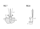
- FIG. 7 shows a substrate 4 of a component which is processed by means of a laser beam 7.
- the focus is preferably below the surface 5 of the substrate 4 and the material of the substrate or the component is evaporated, as indicated by the arrows.
- the laser beam does not move within a plane (percussion method), possibly perpendicular to the surface 8.
- the laser beam 7 is guided along a desired shape of the hole 10 to be produced.
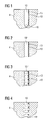
- FIG. 1 shows a first step of the method according to the invention.
- an intermediate hole 10 ' preferably a blind hole, to a certain depth, preferably at least 40%, more preferably at least 60%, preferably 90% or 95% of the final hole depth of a hole 10 is generated.
- the cross section or the diameter of the intermediate hole 10 ' is smaller than the final diameter of the hole 10 to be produced.
- the diameter of the intermediate hole 10' is preferably at least 10% smaller than the final diameter. Preferably, it is 40% to 60% of the final diameter.
- the energy for the production of the intermediate hole 10 ' is to be selected low and it is preferable to set a defocusing of the laser beam in the material.
- the hole breakthrough is performed by a percussion method and preferably with higher energy (at least 20% higher) in the best focus ( FIG. 2 ), preferably without the cross section or diameter of the Hole 10 'is changed.
- the result is a transition through hole 10 ".
- the transition through-hole 10 may be prepolished by a trephining process and the polished hole 10 '''(FIG. Fig. 3 ).
- the radius of the blind hole 10 'or the transition through-hole 10 " is preferably 50% of the final radius or cross-section of the hole 10 to be produced.
- the hole 10 is made from the transition through-hole 10 "or the prepolished hole 10"'finally by a trephining process and the desired final diameter 19 is set ( FIG. 4 ).
- One or more lasers can be used, in particular for the different laser methods (trepanier, percussion).
- FIG. 5 shows a perspective view of a blade 120 or guide vane 130 of a turbomachine, which extends along a longitudinal axis 121.
- the turbomachine may be a gas turbine of an aircraft or a power plant for power generation, a steam turbine or a compressor.
- the blade 120, 130 has along the longitudinal axis 121 consecutively a fastening region 400, a blade platform 403 adjacent thereto and an airfoil 406 and a blade tip 415.
- the blade 130 may have at its blade tip 415 another platform (not shown).
- a blade root 183 is formed, which serves for attachment of the blades 120, 130 to a shaft or a disc (not shown).
- the blade root 183 is designed, for example, as a hammer head. Other designs as Christmas tree or Schwalbenschwanzfuß are possible.
- the blade 120, 130 has a leading edge 409 and a trailing edge 412 for a medium flowing past the airfoil 406.
- Such superalloys are for example from EP 1 204 776 B1 .
- EP 1 306 454 .
- the blade 120, 130 can be made by a casting process, also by directional solidification, by a forging process, by a milling process or combinations thereof.
- Workpieces with a monocrystalline structure or structures are used as components for machines which are exposed to high mechanical, thermal and / or chemical stresses during operation.
- Such monocrystalline workpieces takes place e.g. by directed solidification from the melt.
- These are casting processes in which the liquid metallic alloy is transformed into a monocrystalline structure, i. to the single-crystal workpiece, or directionally solidified.
- dendritic crystals are aligned along the heat flow and form either a columnar grain structure (columnar, ie grains over the entire length run the workpiece and here, the general usage, referred to as directionally solidified) or a monocrystalline structure, ie the entire workpiece consists of a single crystal.
- directionally solidified a columnar grain structure
- monocrystalline structure ie the entire workpiece consists of a single crystal.
- directionally solidified microstructures which means both single crystals that have no grain boundaries or at most small angle grain boundaries, and stem crystal structures that have probably longitudinal grain boundaries but no transverse grain boundaries. These second-mentioned crystalline structures are also known as directionally solidified structures.
- the blades 120, 130 may have coatings against corrosion or oxidation, e.g. M is at least one element of the group iron (Fe), cobalt (Co), nickel (Ni), X is an active element and stands for yttrium (Y) and / or silicon and / or at least one element of the rare ones Earth, or hafnium (Hf)).
- M is at least one element of the group iron (Fe), cobalt (Co), nickel (Ni)
- X is an active element and stands for yttrium (Y) and / or silicon and / or at least one element of the rare ones Earth, or hafnium (Hf)).
- Such alloys are known from the EP 0 486 489 B1 .
- EP 0 412 397 B1 or EP 1 306 454 A1 are known from the EP 0 486 489 B1 .
- the density is preferably 95% of the theoretical density.
- the layer composition comprises Co-30Ni-28Cr-8Al-0.6Y-0.7Si or Co-28Ni-24Cr-10Al-0.6Y.
- nickel-based protective layers such as Ni-10Cr-12Al-0,6Y-3Re are also preferably used or Ni-12Co-21Cr-11Al-0.4Y-2Re or Ni-25Co-17Cr-10Al-0.4Y-1.5Re.
- thermal barrier coating which is preferably the outermost layer, and consists for example of ZrO 2 , Y 2 O 3 -ZrO 2 , ie it is not, partially or completely stabilized by yttria and / or calcium oxide and / or magnesium oxide.
- the thermal barrier coating covers the entire MCrAlX layer.
- suitable coating methods e.g. Electron beam evaporation (EB-PVD) produces stalk-shaped grains in the thermal barrier coating.
- the thermal barrier coating may have porous, micro- or macro-cracked grains for better thermal shock resistance.
- the thermal barrier coating is therefore preferably more porous than the MCrAlX layer.
- Refurbishment means that components 120, 130 may need to be deprotected after use (e.g., by sandblasting). This is followed by removal of the corrosion and / or oxidation layers or products. Optionally, even cracks in the component 120, 130 are repaired. This is followed by a re-coating of the component 120, 130 and a renewed use of the component 120, 130.
- the blade 120, 130 may be hollow or solid. If the blade 120, 130 is to be cooled, it is hollow and may still film cooling holes 418 (indicated by dashed lines) on.
Landscapes
- Engineering & Computer Science (AREA)
- Physics & Mathematics (AREA)
- Optics & Photonics (AREA)
- Plasma & Fusion (AREA)
- Mechanical Engineering (AREA)
- Laser Beam Processing (AREA)
- Turbine Rotor Nozzle Sealing (AREA)
- Re-Forming, After-Treatment, Cutting And Transporting Of Glass Products (AREA)
- Processing Of Stones Or Stones Resemblance Materials (AREA)
Priority Applications (7)
| Application Number | Priority Date | Filing Date | Title |
|---|---|---|---|
| EP13006050.2A EP2712700A1 (de) | 2010-05-04 | 2010-05-04 | Laserbohren ohne Gratbildung |
| EP10004709A EP2384845A1 (de) | 2010-05-04 | 2010-05-04 | Laserbohren ohne Gratbildung |
| RU2011117457/02A RU2011117457A (ru) | 2010-05-04 | 2011-04-29 | Лазерное сверление без образования заусенцев |
| US13/098,539 US20110272387A1 (en) | 2010-05-04 | 2011-05-02 | Laser drilling without burr formation |
| CN2011102114840A CN102284793A (zh) | 2010-05-04 | 2011-05-04 | 不形成毛刺的激光钻孔 |
| CN201410465058.3A CN104308372A (zh) | 2010-05-04 | 2011-05-04 | 不形成毛刺的激光钻孔 |
| US14/444,373 US20140332512A1 (en) | 2010-05-04 | 2014-07-28 | Laser drilling without burr formation |
Applications Claiming Priority (1)
| Application Number | Priority Date | Filing Date | Title |
|---|---|---|---|
| EP10004709A EP2384845A1 (de) | 2010-05-04 | 2010-05-04 | Laserbohren ohne Gratbildung |
Related Child Applications (1)
| Application Number | Title | Priority Date | Filing Date |
|---|---|---|---|
| EP13006050.2A Division EP2712700A1 (de) | 2010-05-04 | 2010-05-04 | Laserbohren ohne Gratbildung |
Publications (1)
| Publication Number | Publication Date |
|---|---|
| EP2384845A1 true EP2384845A1 (de) | 2011-11-09 |
Family
ID=42829559
Family Applications (2)
| Application Number | Title | Priority Date | Filing Date |
|---|---|---|---|
| EP13006050.2A Withdrawn EP2712700A1 (de) | 2010-05-04 | 2010-05-04 | Laserbohren ohne Gratbildung |
| EP10004709A Withdrawn EP2384845A1 (de) | 2010-05-04 | 2010-05-04 | Laserbohren ohne Gratbildung |
Family Applications Before (1)
| Application Number | Title | Priority Date | Filing Date |
|---|---|---|---|
| EP13006050.2A Withdrawn EP2712700A1 (de) | 2010-05-04 | 2010-05-04 | Laserbohren ohne Gratbildung |
Country Status (4)
| Country | Link |
|---|---|
| US (2) | US20110272387A1 (zh) |
| EP (2) | EP2712700A1 (zh) |
| CN (2) | CN104308372A (zh) |
| RU (1) | RU2011117457A (zh) |
Cited By (2)
| Publication number | Priority date | Publication date | Assignee | Title |
|---|---|---|---|---|
| DE102013017129A1 (de) | 2013-10-16 | 2015-04-16 | Daimler Ag | Verfahren zum Herstellen eines Lochs mittels eines Energiestrahls |
| DE102013017126A1 (de) | 2013-10-16 | 2015-04-16 | Daimler Ag | Verfahren zum Herstellen eines Lochs eines Bauteils |
Families Citing this family (6)
| Publication number | Priority date | Publication date | Assignee | Title |
|---|---|---|---|---|
| US9696035B2 (en) * | 2010-10-29 | 2017-07-04 | General Electric Company | Method of forming a cooling hole by laser drilling |
| US11440139B2 (en) | 2018-05-03 | 2022-09-13 | Raytheon Technologies Corporation | Liquid enhanced laser stripping |
| CN109238493B (zh) * | 2018-08-29 | 2020-06-02 | 中南大学 | 一种磨削温度测量方法 |
| CN109746686B (zh) * | 2019-01-14 | 2020-10-23 | 诸暨市轩镨机械科技有限公司 | 一种机械生产用钻孔去毛刺一体机 |
| CN109648193A (zh) * | 2019-01-24 | 2019-04-19 | 西安中科微精光子制造科技有限公司 | 一种激光冲孔装置及方法 |
| CN114193005B (zh) * | 2022-01-23 | 2023-11-21 | 阳江市皓殷智造科技有限公司 | 一种激光切割用稳定器 |
Citations (14)
| Publication number | Priority date | Publication date | Assignee | Title |
|---|---|---|---|---|
| EP0486489B1 (de) | 1989-08-10 | 1994-11-02 | Siemens Aktiengesellschaft | Hochtemperaturfeste korrosionsschutzbeschichtung, insbesondere für gasturbinenbauteile |
| EP0826457A1 (en) * | 1996-08-14 | 1998-03-04 | ROLLS-ROYCE plc | A method of drilling a hole in a workpiece |
| EP0412397B1 (de) | 1989-08-10 | 1998-03-25 | Siemens Aktiengesellschaft | Rheniumhaltige Schutzbeschichtung mit grosser Korrosions- und/oder Oxidationsbeständigkeit |
| EP0892090A1 (de) | 1997-02-24 | 1999-01-20 | Sulzer Innotec Ag | Verfahren zum Herstellen von einkristallinen Strukturen |
| EP0786017B1 (de) | 1994-10-14 | 1999-03-24 | Siemens Aktiengesellschaft | Schutzschicht zum schutz eines bauteils gegen korrosion, oxidation und thermische überbeanspruchung sowie verfahren zu ihrer herstellung |
| WO1999067435A1 (en) | 1998-06-23 | 1999-12-29 | Siemens Aktiengesellschaft | Directionally solidified casting with improved transverse stress rupture strength |
| US6024792A (en) | 1997-02-24 | 2000-02-15 | Sulzer Innotec Ag | Method for producing monocrystalline structures |
| WO2000044949A1 (en) | 1999-01-28 | 2000-08-03 | Siemens Aktiengesellschaft | Nickel base superalloy with good machinability |
| US20020104831A1 (en) * | 2001-02-08 | 2002-08-08 | The Regents Of The University Of California | High precision, rapid laser hole drilling |
| EP1306454A1 (de) | 2001-10-24 | 2003-05-02 | Siemens Aktiengesellschaft | Rhenium enthaltende Schutzschicht zum Schutz eines Bauteils gegen Korrosion und Oxidation bei hohen Temperaturen |
| EP1319729A1 (de) | 2001-12-13 | 2003-06-18 | Siemens Aktiengesellschaft | Hochtemperaturbeständiges Bauteil aus einkristalliner oder polykristalliner Nickel-Basis-Superlegierung |
| EP1204776B1 (de) | 1999-07-29 | 2004-06-02 | Siemens Aktiengesellschaft | Hochtemperaturbeständiges bauteil und verfahren zur herstellung des hochtemperaturbeständigen bauteils |
| EP1806203A1 (de) * | 2006-01-10 | 2007-07-11 | Siemens Aktiengesellschaft | Verfahren zur Herstellung eines Lochs |
| EP1927426A1 (fr) * | 2006-11-30 | 2008-06-04 | Snecma | Procédé de perçage laser d'une pièce en matériau composite à matrice céramique |
Family Cites Families (15)
| Publication number | Priority date | Publication date | Assignee | Title |
|---|---|---|---|---|
| JP2662041B2 (ja) * | 1989-07-28 | 1997-10-08 | 株式会社日立製作所 | レーザビームを用いた孔あけ加工法及びこれを利用した燃料噴射弁のノズルの製造方法 |
| US5744780A (en) * | 1995-09-05 | 1998-04-28 | The United States Of America As Represented By The United States Department Of Energy | Apparatus for precision micromachining with lasers |
| US5771577A (en) * | 1996-05-17 | 1998-06-30 | General Electric Company | Method for making a fluid cooled article with protective coating |
| US5837964A (en) * | 1998-01-16 | 1998-11-17 | Chromalloy Gas Turbine Corporation | Laser drilling holes in components by combined percussion and trepan drilling |
| US20020066179A1 (en) * | 2000-12-01 | 2002-06-06 | Hall Hendley W. | System and method for metalization of deep vias |
| DE10106809A1 (de) * | 2001-02-14 | 2002-09-19 | Siemens Ag | Verfahren zur Herstellung eines Lochs in einem Körper, insbesondere eines Einspritzlochs in einem Kraftstoffinjektor |
| GB2381489B (en) * | 2001-10-30 | 2004-11-17 | Rolls Royce Plc | Method of forming a shaped hole |
| US20040112881A1 (en) * | 2002-04-11 | 2004-06-17 | Bloemeke Stephen Roger | Circle laser trepanning |
| EP1813378A3 (de) * | 2003-10-06 | 2007-10-31 | Siemens Aktiengesellschaft | Verfahren zur Herstellung eines Lochs |
| TW200541434A (en) * | 2004-04-30 | 2005-12-16 | Hitachi Via Mechanics Ltd | Printed circuit board and method for processing printed circuit board and method for manufacturing printed circuit board |
| JP2006095563A (ja) * | 2004-09-29 | 2006-04-13 | Denso Corp | 高密度エネルギービームによるバリ除去方法およびバリ除去装置 |
| JP4787091B2 (ja) * | 2006-06-27 | 2011-10-05 | 株式会社ディスコ | ビアホールの加工方法 |
| EP2105240B1 (de) * | 2008-03-28 | 2011-10-05 | Siemens Aktiengesellschaft | Verfahren zur Fertigung einer Bohrung |
| KR101036879B1 (ko) * | 2008-08-27 | 2011-05-25 | 주식회사 이오테크닉스 | 드릴링 장치 및 드릴링 방법 |
| CN101658975A (zh) * | 2009-09-11 | 2010-03-03 | 克恩-里伯斯(太仓)有限公司 | 一种脉冲式激光去毛刺的方法 |
-
2010
- 2010-05-04 EP EP13006050.2A patent/EP2712700A1/de not_active Withdrawn
- 2010-05-04 EP EP10004709A patent/EP2384845A1/de not_active Withdrawn
-
2011
- 2011-04-29 RU RU2011117457/02A patent/RU2011117457A/ru not_active Application Discontinuation
- 2011-05-02 US US13/098,539 patent/US20110272387A1/en not_active Abandoned
- 2011-05-04 CN CN201410465058.3A patent/CN104308372A/zh active Pending
- 2011-05-04 CN CN2011102114840A patent/CN102284793A/zh active Pending
-
2014
- 2014-07-28 US US14/444,373 patent/US20140332512A1/en not_active Abandoned
Patent Citations (14)
| Publication number | Priority date | Publication date | Assignee | Title |
|---|---|---|---|---|
| EP0412397B1 (de) | 1989-08-10 | 1998-03-25 | Siemens Aktiengesellschaft | Rheniumhaltige Schutzbeschichtung mit grosser Korrosions- und/oder Oxidationsbeständigkeit |
| EP0486489B1 (de) | 1989-08-10 | 1994-11-02 | Siemens Aktiengesellschaft | Hochtemperaturfeste korrosionsschutzbeschichtung, insbesondere für gasturbinenbauteile |
| EP0786017B1 (de) | 1994-10-14 | 1999-03-24 | Siemens Aktiengesellschaft | Schutzschicht zum schutz eines bauteils gegen korrosion, oxidation und thermische überbeanspruchung sowie verfahren zu ihrer herstellung |
| EP0826457A1 (en) * | 1996-08-14 | 1998-03-04 | ROLLS-ROYCE plc | A method of drilling a hole in a workpiece |
| US6024792A (en) | 1997-02-24 | 2000-02-15 | Sulzer Innotec Ag | Method for producing monocrystalline structures |
| EP0892090A1 (de) | 1997-02-24 | 1999-01-20 | Sulzer Innotec Ag | Verfahren zum Herstellen von einkristallinen Strukturen |
| WO1999067435A1 (en) | 1998-06-23 | 1999-12-29 | Siemens Aktiengesellschaft | Directionally solidified casting with improved transverse stress rupture strength |
| WO2000044949A1 (en) | 1999-01-28 | 2000-08-03 | Siemens Aktiengesellschaft | Nickel base superalloy with good machinability |
| EP1204776B1 (de) | 1999-07-29 | 2004-06-02 | Siemens Aktiengesellschaft | Hochtemperaturbeständiges bauteil und verfahren zur herstellung des hochtemperaturbeständigen bauteils |
| US20020104831A1 (en) * | 2001-02-08 | 2002-08-08 | The Regents Of The University Of California | High precision, rapid laser hole drilling |
| EP1306454A1 (de) | 2001-10-24 | 2003-05-02 | Siemens Aktiengesellschaft | Rhenium enthaltende Schutzschicht zum Schutz eines Bauteils gegen Korrosion und Oxidation bei hohen Temperaturen |
| EP1319729A1 (de) | 2001-12-13 | 2003-06-18 | Siemens Aktiengesellschaft | Hochtemperaturbeständiges Bauteil aus einkristalliner oder polykristalliner Nickel-Basis-Superlegierung |
| EP1806203A1 (de) * | 2006-01-10 | 2007-07-11 | Siemens Aktiengesellschaft | Verfahren zur Herstellung eines Lochs |
| EP1927426A1 (fr) * | 2006-11-30 | 2008-06-04 | Snecma | Procédé de perçage laser d'une pièce en matériau composite à matrice céramique |
Cited By (2)
| Publication number | Priority date | Publication date | Assignee | Title |
|---|---|---|---|---|
| DE102013017129A1 (de) | 2013-10-16 | 2015-04-16 | Daimler Ag | Verfahren zum Herstellen eines Lochs mittels eines Energiestrahls |
| DE102013017126A1 (de) | 2013-10-16 | 2015-04-16 | Daimler Ag | Verfahren zum Herstellen eines Lochs eines Bauteils |
Also Published As
| Publication number | Publication date |
|---|---|
| US20110272387A1 (en) | 2011-11-10 |
| US20140332512A1 (en) | 2014-11-13 |
| EP2712700A1 (de) | 2014-04-02 |
| CN102284793A (zh) | 2011-12-21 |
| RU2011117457A (ru) | 2012-11-10 |
| CN104308372A (zh) | 2015-01-28 |
Similar Documents
| Publication | Publication Date | Title |
|---|---|---|
| EP2467228B1 (de) | Verfahren zur herstellung eines asymmetrischen diffusors unter verwendung verschiedener laserstellungen | |
| EP2384845A1 (de) | Laserbohren ohne Gratbildung | |
| EP2591872A1 (de) | Umschmelzverfahren und anschließendes Auffüllen und Bauteil | |
| EP2286955A1 (de) | Verfahren zur Herstellung eines Lochs unter Verwendung verschiedener Laserstellungen | |
| EP3500395B1 (de) | Dreistufiger prozess zur kühlluftbohrerzeugung mittels nanosekunden- und millisekundenlaser und bauteil | |
| EP2865781A1 (de) | Zweilagige keramische Schicht mit unterschiedlichen Mikrostrukturen | |
| EP2308628A1 (de) | Verfahren zum Entfernen einer angelöteten Komponente mit lokaler Erwärmung der Lotstelle | |
| EP2186594A1 (de) | Verfahren und Vorrichtung zur Vorwärmung beim Schweißen unter Verwendung eines zweiten Laserstrahles | |
| DE102013224568A1 (de) | Verfahren zur Erzeugung einer Fase, Bauteil mit Fase und Vorrichtung | |
| EP2725235A1 (de) | Unterschiedlich raue Schaufel und zugehörige Herstellungsverfahren | |
| EP2088224A1 (de) | Verfahren zur Herstellung einer rauen Schicht und ein Schichtsystem | |
| EP2335855A1 (de) | Füllstoff beim Bohren von Durchgangslöchern von hohlen Bauteilen, ein Verfahren und Vorrichtung dafür | |
| EP2604377B1 (de) | Verfahren zur Laserbearbeitung eines Schichtsystems mit keramischer Schicht | |
| EP2774710A1 (de) | Oberflächen und Rissreparatur durch verschiedene Lotmaterialien | |
| EP2591877A1 (de) | Umschmelzverfahren unter reaktivem Gasgemisch | |
| WO2015104098A1 (de) | Verfahren zum schutz eines bauteils, verfahren zum laserbohren und bauteil | |
| EP2591876A1 (de) | Verfahren zum Auftragsschweißen eines Bauteiles aus einkristallinem oder gerichtet erstarrtem Metall | |
| EP2730364A1 (de) | Schweißbadsicherung am Randbereich | |
| EP2604378B1 (de) | Wiederöffnung von Kühlluftbohrungen mit Nanosekundenlaser im Mikrosekundenbereich | |
| EP2340909A1 (de) | Verschließen von kreisrunden und ovalen Öffnungen im Kronenboden von Turbinenlaufschaufeln mittels Kegelstopfen | |
| WO2015078615A1 (de) | Vorrichtung zur maskierung auf wolframlegierungsbasis und eine wolframlegierung | |
| EP2322681A1 (de) | Verfahren zur Vermeidung von Rekristallisierung durch Alitierung | |
| EP2498941B1 (de) | Funkenerosives schneiden mit dicker ablaufender drahtelektrode | |
| EP2586561A1 (de) | Strategie der Verfahrbewegung zur Erhaltung des einkristallinen Aufbaus beim Auftragsschweißen | |
| WO2013079246A1 (de) | Laserbohren von durchgangsbohrungen ohne schutz im inneren |
Legal Events
| Date | Code | Title | Description |
|---|---|---|---|
| AK | Designated contracting states |
Kind code of ref document: A1 Designated state(s): AL AT BE BG CH CY CZ DE DK EE ES FI FR GB GR HR HU IE IS IT LI LT LU LV MC MK MT NL NO PL PT RO SE SI SK SM TR |
|
| AX | Request for extension of the european patent |
Extension state: BA ME RS |
|
| PUAI | Public reference made under article 153(3) epc to a published international application that has entered the european phase |
Free format text: ORIGINAL CODE: 0009012 |
|
| 17P | Request for examination filed |
Effective date: 20111205 |
|
| 17Q | First examination report despatched |
Effective date: 20120503 |
|
| RAP1 | Party data changed (applicant data changed or rights of an application transferred) |
Owner name: SIEMENS AKTIENGESELLSCHAFT |
|
| GRAP | Despatch of communication of intention to grant a patent |
Free format text: ORIGINAL CODE: EPIDOSNIGR1 |
|
| INTG | Intention to grant announced |
Effective date: 20140307 |
|
| STAA | Information on the status of an ep patent application or granted ep patent |
Free format text: STATUS: THE APPLICATION IS DEEMED TO BE WITHDRAWN |
|
| 18D | Application deemed to be withdrawn |
Effective date: 20140718 |