EP2384786A1 - Electrode lead in particular for use with a medical implant - Google Patents
Electrode lead in particular for use with a medical implant Download PDFInfo
- Publication number
- EP2384786A1 EP2384786A1 EP11162223A EP11162223A EP2384786A1 EP 2384786 A1 EP2384786 A1 EP 2384786A1 EP 11162223 A EP11162223 A EP 11162223A EP 11162223 A EP11162223 A EP 11162223A EP 2384786 A1 EP2384786 A1 EP 2384786A1
- Authority
- EP
- European Patent Office
- Prior art keywords
- electrode lead
- capacitor
- ring element
- coil conductor
- electrode
- Prior art date
- Legal status (The legal status is an assumption and is not a legal conclusion. Google has not performed a legal analysis and makes no representation as to the accuracy of the status listed.)
- Granted
Links
- 239000007943 implant Substances 0.000 title claims abstract description 7
- 239000004020 conductor Substances 0.000 claims abstract description 64
- 239000003990 capacitor Substances 0.000 claims abstract description 63
- 238000000576 coating method Methods 0.000 claims description 23
- 239000011248 coating agent Substances 0.000 claims description 20
- 238000009413 insulation Methods 0.000 claims description 12
- WABPQHHGFIMREM-UHFFFAOYSA-N lead(0) Chemical compound [Pb] WABPQHHGFIMREM-UHFFFAOYSA-N 0.000 claims description 10
- 229910052751 metal Inorganic materials 0.000 claims description 7
- 239000002184 metal Substances 0.000 claims description 7
- RTAQQCXQSZGOHL-UHFFFAOYSA-N Titanium Chemical compound [Ti] RTAQQCXQSZGOHL-UHFFFAOYSA-N 0.000 claims description 5
- 239000010936 titanium Substances 0.000 claims description 5
- 229910052719 titanium Inorganic materials 0.000 claims description 5
- 238000004804 winding Methods 0.000 claims description 5
- VYPSYNLAJGMNEJ-UHFFFAOYSA-N silicon dioxide Inorganic materials O=[Si]=O VYPSYNLAJGMNEJ-UHFFFAOYSA-N 0.000 description 18
- PNEYBMLMFCGWSK-UHFFFAOYSA-N Alumina Chemical compound [O-2].[O-2].[O-2].[Al+3].[Al+3] PNEYBMLMFCGWSK-UHFFFAOYSA-N 0.000 description 8
- 239000000377 silicon dioxide Substances 0.000 description 8
- OKTJSMMVPCPJKN-UHFFFAOYSA-N Carbon Chemical compound [C] OKTJSMMVPCPJKN-UHFFFAOYSA-N 0.000 description 6
- NRTOMJZYCJJWKI-UHFFFAOYSA-N Titanium nitride Chemical compound [Ti]#N NRTOMJZYCJJWKI-UHFFFAOYSA-N 0.000 description 6
- 229920000052 poly(p-xylylene) Polymers 0.000 description 6
- -1 polydimethylsiloxane Polymers 0.000 description 6
- 229920002635 polyurethane Polymers 0.000 description 6
- 239000004814 polyurethane Substances 0.000 description 6
- 238000010276 construction Methods 0.000 description 5
- 229910003481 amorphous carbon Inorganic materials 0.000 description 4
- 229910002113 barium titanate Inorganic materials 0.000 description 4
- 229910052799 carbon Inorganic materials 0.000 description 4
- 239000000919 ceramic Substances 0.000 description 4
- 239000004205 dimethyl polysiloxane Substances 0.000 description 4
- 235000013870 dimethyl polysiloxane Nutrition 0.000 description 4
- 238000002595 magnetic resonance imaging Methods 0.000 description 4
- 239000002923 metal particle Substances 0.000 description 4
- 229920000435 poly(dimethylsiloxane) Polymers 0.000 description 4
- 229920000139 polyethylene terephthalate Polymers 0.000 description 4
- 239000005020 polyethylene terephthalate Substances 0.000 description 4
- 229920000642 polymer Polymers 0.000 description 4
- 229910010271 silicon carbide Inorganic materials 0.000 description 4
- 235000012239 silicon dioxide Nutrition 0.000 description 4
- 239000000126 substance Substances 0.000 description 4
- XUIMIQQOPSSXEZ-UHFFFAOYSA-N Silicon Chemical compound [Si] XUIMIQQOPSSXEZ-UHFFFAOYSA-N 0.000 description 3
- 238000010438 heat treatment Methods 0.000 description 3
- 230000007774 longterm Effects 0.000 description 3
- 239000004033 plastic Substances 0.000 description 3
- 229920003023 plastic Polymers 0.000 description 3
- 229910052710 silicon Inorganic materials 0.000 description 3
- 239000010703 silicon Substances 0.000 description 3
- 229920001651 Cyanoacrylate Polymers 0.000 description 2
- 239000004593 Epoxy Substances 0.000 description 2
- MWCLLHOVUTZFKS-UHFFFAOYSA-N Methyl cyanoacrylate Chemical compound COC(=O)C(=C)C#N MWCLLHOVUTZFKS-UHFFFAOYSA-N 0.000 description 2
- 239000004952 Polyamide Substances 0.000 description 2
- 239000004642 Polyimide Substances 0.000 description 2
- BLRPTPMANUNPDV-UHFFFAOYSA-N Silane Chemical compound [SiH4] BLRPTPMANUNPDV-UHFFFAOYSA-N 0.000 description 2
- 239000004809 Teflon Substances 0.000 description 2
- 229920006362 Teflon® Polymers 0.000 description 2
- GWEVSGVZZGPLCZ-UHFFFAOYSA-N Titan oxide Chemical compound O=[Ti]=O GWEVSGVZZGPLCZ-UHFFFAOYSA-N 0.000 description 2
- NIXOWILDQLNWCW-UHFFFAOYSA-N acrylic acid group Chemical group C(C=C)(=O)O NIXOWILDQLNWCW-UHFFFAOYSA-N 0.000 description 2
- 239000004411 aluminium Substances 0.000 description 2
- 229910052782 aluminium Inorganic materials 0.000 description 2
- XAGFODPZIPBFFR-UHFFFAOYSA-N aluminium Chemical compound [Al] XAGFODPZIPBFFR-UHFFFAOYSA-N 0.000 description 2
- JRPBQTZRNDNNOP-UHFFFAOYSA-N barium titanate Chemical compound [Ba+2].[Ba+2].[O-][Ti]([O-])([O-])[O-] JRPBQTZRNDNNOP-UHFFFAOYSA-N 0.000 description 2
- 238000005452 bending Methods 0.000 description 2
- 239000008280 blood Substances 0.000 description 2
- 210000004369 blood Anatomy 0.000 description 2
- 230000000747 cardiac effect Effects 0.000 description 2
- 239000003610 charcoal Substances 0.000 description 2
- 229910052593 corundum Inorganic materials 0.000 description 2
- 229910003460 diamond Inorganic materials 0.000 description 2
- 239000010432 diamond Substances 0.000 description 2
- 239000006185 dispersion Substances 0.000 description 2
- 229920001971 elastomer Polymers 0.000 description 2
- 239000000806 elastomer Substances 0.000 description 2
- 239000000945 filler Substances 0.000 description 2
- 239000012530 fluid Substances 0.000 description 2
- PCHJSUWPFVWCPO-UHFFFAOYSA-N gold Chemical compound [Au] PCHJSUWPFVWCPO-UHFFFAOYSA-N 0.000 description 2
- 239000010931 gold Substances 0.000 description 2
- 229910052737 gold Inorganic materials 0.000 description 2
- 239000000463 material Substances 0.000 description 2
- 239000007769 metal material Substances 0.000 description 2
- CXQXSVUQTKDNFP-UHFFFAOYSA-N octamethyltrisiloxane Chemical compound C[Si](C)(C)O[Si](C)(C)O[Si](C)(C)C CXQXSVUQTKDNFP-UHFFFAOYSA-N 0.000 description 2
- 238000004987 plasma desorption mass spectroscopy Methods 0.000 description 2
- 229920003223 poly(pyromellitimide-1,4-diphenyl ether) Polymers 0.000 description 2
- 229920002647 polyamide Polymers 0.000 description 2
- 229920000728 polyester Polymers 0.000 description 2
- 229920001721 polyimide Polymers 0.000 description 2
- 229920001343 polytetrafluoroethylene Polymers 0.000 description 2
- 239000004810 polytetrafluoroethylene Substances 0.000 description 2
- 239000010453 quartz Substances 0.000 description 2
- 229910000077 silane Inorganic materials 0.000 description 2
- HBMJWWWQQXIZIP-UHFFFAOYSA-N silicon carbide Chemical compound [Si+]#[C-] HBMJWWWQQXIZIP-UHFFFAOYSA-N 0.000 description 2
- 239000004447 silicone coating Substances 0.000 description 2
- 229910052715 tantalum Inorganic materials 0.000 description 2
- GUVRBAGPIYLISA-UHFFFAOYSA-N tantalum atom Chemical compound [Ta] GUVRBAGPIYLISA-UHFFFAOYSA-N 0.000 description 2
- OGIDPMRJRNCKJF-UHFFFAOYSA-N titanium oxide Inorganic materials [Ti]=O OGIDPMRJRNCKJF-UHFFFAOYSA-N 0.000 description 2
- WFKWXMTUELFFGS-UHFFFAOYSA-N tungsten Chemical compound [W] WFKWXMTUELFFGS-UHFFFAOYSA-N 0.000 description 2
- 229910052721 tungsten Inorganic materials 0.000 description 2
- 239000010937 tungsten Substances 0.000 description 2
- 229910001845 yogo sapphire Inorganic materials 0.000 description 2
- 208000033988 Device pacing issue Diseases 0.000 description 1
- 239000003637 basic solution Substances 0.000 description 1
- 230000009286 beneficial effect Effects 0.000 description 1
- 230000005540 biological transmission Effects 0.000 description 1
- 230000000903 blocking effect Effects 0.000 description 1
- 238000010586 diagram Methods 0.000 description 1
- 239000003989 dielectric material Substances 0.000 description 1
- 230000000694 effects Effects 0.000 description 1
- 238000011010 flushing procedure Methods 0.000 description 1
- 230000010354 integration Effects 0.000 description 1
- 238000004519 manufacturing process Methods 0.000 description 1
- 238000007747 plating Methods 0.000 description 1
- 239000000243 solution Substances 0.000 description 1
Images


Classifications
-
- A—HUMAN NECESSITIES
- A61—MEDICAL OR VETERINARY SCIENCE; HYGIENE
- A61N—ELECTROTHERAPY; MAGNETOTHERAPY; RADIATION THERAPY; ULTRASOUND THERAPY
- A61N1/00—Electrotherapy; Circuits therefor
- A61N1/02—Details
- A61N1/04—Electrodes
- A61N1/05—Electrodes for implantation or insertion into the body, e.g. heart electrode
- A61N1/056—Transvascular endocardial electrode systems
- A61N1/0563—Transvascular endocardial electrode systems specially adapted for defibrillation or cardioversion
-
- A—HUMAN NECESSITIES
- A61—MEDICAL OR VETERINARY SCIENCE; HYGIENE
- A61N—ELECTROTHERAPY; MAGNETOTHERAPY; RADIATION THERAPY; ULTRASOUND THERAPY
- A61N1/00—Electrotherapy; Circuits therefor
- A61N1/18—Applying electric currents by contact electrodes
- A61N1/32—Applying electric currents by contact electrodes alternating or intermittent currents
- A61N1/36—Applying electric currents by contact electrodes alternating or intermittent currents for stimulation
- A61N1/362—Heart stimulators
- A61N1/37—Monitoring; Protecting
Definitions
- the invention refers to an electrode lead in particular for use with a medical implant according to the preamble of claim 1.
- Electrode leads for such use are known in a wide variety of embodiments, e. g. cardiac pacemaker leads for sensing and/or pacing, or active leads for implantable defibrillators.
- a problem occurs with such electrode leads, when they are placed in strong dynamic magnetic fields, like is the case during magnetic resonance imaging or close to radio transmission stations. Due to electromagnetic interference (EMI), radio frequency (RF) energy is picked up by the electrode lead. This energy exits the electrode lead at an electrode pole, which is connected and/or connectable to the electrode lead, like a tip electrode of a pacemaker electrode lead. Due to the high frequency, the exiting energy causes a heating of the surrounding tissue or blood what in turn may destroy the surrounding of the electrode, like living tissue. Within the cardiac environment, this can increase e. g. pacing thresholds of an electrode lead used as a pacemaker lead, in the worst case this heating could make the lead ineffective.
- EMI electromagnetic interference
- RF radio frequency
- Such electrode leads used in practice, as they are produced and marketed by the applicant of US 7,363,090 show filter constructions in which the capacitor and the inductor are hermetically sealed in a drum which forms a cylindrical stiff element of considerable dimensions. Due to the large and bulky housing of this known filter, the electrode lead equipped with this filter has an unacceptable stiff tip section which is problematic when introducing the electrode lead into a body vessel. Bulky long stiff regions in the tip section may cause perforation of the body vessel which is a serious incident when positioning the electrode lead.
- a further disadvantage of the known electrode lead with band stop filter is the fact that the electrode lead does not dispose of a central continuous lumen for guiding the electrode lead over a guide wire or mandrel because of the bulky massive filter element.
- the electrode lead according to the invention basically uses known components of such electrode leads, namely, first and second ring elements at the distal end of the electrode lead, like they are used with known electrodes leads for ring or tip electrodes.
- Such ring elements are positioned coaxially in the lead electrode body and have coaxial, central lumens for a guide wire or the like.
- the coil conductor between the first and second ring element accords to a usual wire coil used in medical implant electrode leads and, thus, also shows a central coaxial lumen for a guide wire or the like.
- a part existing per se in a medical lead is used to incorporate an element of a high frequency filter.
- the first ring element is adapted to be a capacitor including an external capacitor sleeve and an internal capacitor sleeve which together form an electrical component having a capacitance value which is defined by the dimensions of the capacitor sleeves, their radial distance and the dielectric constant of the dielectricum placed between the two capacitor sleeves.
- This capacitor forms one part of the filter element, whereas the coil conductor between the first and second ring element is adapted to form an inductance and, thus, realizes the second necessary component for a filter element blocking high frequency currents induced by RF signals of MRI systems.
- the electrode lead according to the invention shows the same mechanical and long term stability characteristics as known electrode leads. Further on, the novel electrode lead according to the invention still has an inner lumen. Finally, albeit the implementation of a capacitor and an inductance of the filter element thinner electrode leads can be constructed, as the first ring element forming the capacitor and the coil conductor are geometrically placed in series, thus, not requiring extra space in radial direction. Although the overall length of the filter element might be quite long, it can be flexible due to the coil conductor forming the inductance resulting in a more flexible construction as compared to the known solutions with massive, bulky housed filter elements of the prior art.
- the external and internal capacitor sleeve of the capacitor are separated by a dielectricum which is adapted to match the inductance of the coil conductor.
- the capacitor can be adjusted to show the specified filter performance to create a tank filter or a band stop filter etc.
- the dielectricum is a dielectric coating, which might be realized by using:
- the capacitor As to the integration of the capacitor, it is possible to accommodate same in a flexible insulation tube of the electrode lead.
- the connector is fixed at a given longitudinal position within the electrode lead.
- the coil conductor realizing the inductance is made of a high conductive material or coated with same.
- the coil conductor can be matched to the capacitance of the capacitor to achieve a desired filter performance of the filter element.
- At least a partial length of the latter is accommodated in a stiff portion of the electrode body. This means that the coil windings do not change their relative position, thus, leading to a constant inductance value compared to a flexible coil in which deforming the coil would lead to a variation in the inductance value.
- a preferred embodiment provides for an addition lead wire which shunts the flexible coil windings.
- a lead wire may be provided which extends through the coil conductor.
- this additional lead wire may be coiled into the coil conductor, thus, saving space in the region of the inner diameter of the coil conductor.
- the first ring element implementing the capacitor may be surrounded by an external metallic ring surface which may be realized by a metal coating fixed to the capacitor via an insulating coating.
- This design helps to decouple high frequency electromagnetic energy generated by the RF frequency in MRI applications. By this additional dissipation of energy, the heating of the electrode (s) is further minimized.
- the inner capacitor sleeve of the first ring element may be realized by a coating, preferably of titanium.
- another preferred embodiment refers to a structure of a first ring element which is comprised of two coaxially fitted standard ring parts, which, however, do not form a capacitor.
- This function is fulfilled by a separate capacitor, preferably a micro capacitor which is contacted to at least one of these ring parts.
- the advantage of this construction lies in the fact that as a capacitor a standard electronic component can be used. Further on, the whole structure of two ring parts and the capacitor can be assembled easier even using plastic ring parts.
- the electrode lead includes an elongated electrode body 1 with a proximal and distal end 2, 3.
- the electrode body 1 is defined by an elongated flexible insulation tube 4 which is produced e. g. from a silicon tube.
- a first coil conductor 5 connects the medical implant (not shown) at the proximal end of the electrode body 1 with the distal end 3.
- This coil conductor 5 is a standard lead coil used in such electrode leads and is made e. g. from medical steal material MP35N with an wire diameter of 0.12 mm.
- the coil conductor 5 terminates at a first ring element 6 which is positioned coaxially in the electrode body 1 of the electrode lead.
- This first ring element 6 implements a capacitor 7 which includes an external capacitor sleeve 8, an internal capacitor sleeve and a dielectric coating 10 placed between the external and internal capacitor sleeve 8, 9.
- the first ring element 6 is covered by the insulation tube 4 and slidably positioned within the lumen 11 of the insulation tube 4.
- the external sleeve 8 is terminated by a proximal ring 12 which is contacted by the distal end of the coil conductor 5.
- a second coil conductor 13 is placed within the lumen 11 of the insulation tube 4 in coaxial manner as concerns the longitudinal axis of the electrode body.
- the windings 14 of this coil conductor 13 are made of the high-conductive metal material or - as is depicted in Fig. 1 - may have a special high-conductive surface coating 15 on the standard MP35N coil wire 16 to provide long term inductivity stability and a proper quality or performance value.
- the specification of the coil conductor 13 is adapted to match its inductance L to the capacitance C of the capacitor 7.
- the electrode body 1 is terminated with a second ring element 17 which may be a tip electrode of the electrode lead.
- This ring element again is positioned coaxial to the longitudinal axis of the electrode body 1. All central openings of the first coil conductor 5, the first ring element 6, the second coil conductor 13 and the second ring element 17 form a central feed-through 18 depicted in dashed lines in Fig. 1 . As is depicted in dotted lines, a guide wire GW can be fed through the feed-through 18 of the electrode lead.
- the second coil conductor 13 is electrically connected to the external capacitor sleeve 8 by means of a distal ring 19 on the external capacitor sleeve 8.
- the distal end of the coil conductor 13 is mechanically and electrically connected to a shoulder 20 at the proximal end of the ring element 17.
- the further electrical connection is provided for between the inner conductive surface 21 of the ring element 17 and a contact ring 22 fixed to the internal capacitor sleeve 9 of the capacitor 7.
- the connector is an insulated wire 23 which may be coiled or winded together with a coil conductor 13 to save space within the inner diameter of the coil conductor 13.
- the first ring element 6 forming the capacitor 7 with the capacitance C and the coil conductor 13 providing for the conductance L are switched in parallel, both being connected to the coil conductor 5 arriving from the proximal end and to the ring element 17 at the distal end 3 of the electrode body.
- the filter element formed by the capacitor 7 and the coil conductor 13 have a specified filter performance to block RF currents to enter the distal end of the electrode body and, especially, the ring element 17.
- Fig. 1 shows some restrictions as to the stability of the inductance L of the coil conductor 13, as the latter is flexible. Due to the varying geometry of the coil conductor, the inductance L varies when bending the coil conductor 13, thus, leading to a (small) mismatch of the inductance L as concerns the capacitance C. The embodiment of Fig. 2 avoids this problem.
- a partial length of the coil conductor 13 starting from its distal end to about 60% of its length towards the proximal end 2 is accommodated in a stiff portion 24 depicted by bold lines in the insulation tube 4 of the electrode body 1.
- the remaining portion 25 of the coil conductor 13 is still positioned in the mechanically flexible region of the insulation tube 4 and, thus, can still be bended to facilitate the advancement of the electrode lead through a body vessel.
- the coil wires 16 are stably positioned, thus, avoiding any variation in the proper inductance L.
- the coil wires in this remaining portion 25 are bypassed by a shunt wire 26 connecting the rigid portion of the coil conductor 13 directly to the proximal end 27 of the coil conductor 13.
- the shunt wire is made of a high conductive metal material and has a negligible inductance. In case the shunt wire connection at one of its ends fails, the coil conductor 13 together with the capacitor 7 still serves as a backup DC connection for normal operation of the electrode lead.
- Fig. 2 shows one stiff portion of the coil conductor
- the first ring element 6 implementing the capacitor 7 further comprises an external dielectric coating 28 which insulates the first ring element 6 at the external side.
- the insulation tube 4 is interrupted at the location of the first ring element 6.
- the advantage of this embodiment lies in the fact that the dielectric coating 28 may be much thinner than the insulation tube 4.
- the capacitor 7 can have a larger open inner diameter giving better access to e.g. guide wires to be inserted into the electrode lead.
- the drawing figure is a rough sketch which is not reflecting these thickness relations properly.
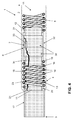
- the embodiment according to Fig. 4 differs from the previous embodiments as concerns the construction of a first ring element 6 which is no capacitor in this case, but welded together from two standard rings 30 which have an inner conductive surface 31, e.g. made of plated titanium. Both rings 30 are welded together via a weld joint 32 depicted in dotted dashed lines in Fig. 4 .
- a standard micro capacitor 33 is used, which is contacted to the conductive surface 31 of one of the standard rings 30 on the one hand and via a wire connection 34 to the second ring element 17 at the distal end 3 of the electrode body 1.
- Aforesaid construction facilitates the manufacturing process, as the micro capacitor 33 may be contacted to the one ring 30 first. Afterwards both rings 30 are welded together. Thus the contacts of the capacitor 33 are also well protected.
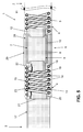
- the last drawing Fig. 5 shows another version of the first ring element 6 which is a development of the embodiment of Fig. 3 .
- the external dielectric coating 28 is further surrounded by an external metallic ring surface 29.
- This metal plating over the dielectric coating 28 serves the purpose of shielding the dielectric coating 28 from blood contact to ensure long term stability and biocompatibility. Boundary effects from the metal surface 29 or the ability to bring the surface in a flushing relationship to the neighbouring elements can also be a beneficial effect from the additional outer metal ring surface 29.
- dielectric materials and coatings cited above may be formed from materials like:
Landscapes
- Health & Medical Sciences (AREA)
- Heart & Thoracic Surgery (AREA)
- Cardiology (AREA)
- Radiology & Medical Imaging (AREA)
- Biomedical Technology (AREA)
- Nuclear Medicine, Radiotherapy & Molecular Imaging (AREA)
- Engineering & Computer Science (AREA)
- Life Sciences & Earth Sciences (AREA)
- Animal Behavior & Ethology (AREA)
- General Health & Medical Sciences (AREA)
- Public Health (AREA)
- Veterinary Medicine (AREA)
- Vascular Medicine (AREA)
- Electrotherapy Devices (AREA)
Abstract
- an elongated electrode body (1) with a proximal and a distal end (3),
- at least one conductor (5) leading from the proximal towards the distal end (3) of the electrode lead,
- a first ring element (6) at the distal end (3) of the electrode lead connected to the conductor (5) and being positioned coaxially in the lead electrode body (1),
- a second ring element (17) spaced distally of the first ring element (6) and being positioned coaxially in the lead electrode body (1),
- a coil conductor (5) between the first and second ring element (17), wherein
- the coil conductor (5) is adapted to form an inductance (L) which is in parallel circuitry with the capacitor (7) to form a filter element in the conductor (5), and
- the first ring element (6), the coil conductor (5) and the second ring element (17) comprise a central feedthrough (18) for a guidance element (GW) for the electrode lead.
Description
- The invention refers to an electrode lead in particular for use with a medical implant according to the preamble of claim 1.
- Electrode leads for such use are known in a wide variety of embodiments, e. g. cardiac pacemaker leads for sensing and/or pacing, or active leads for implantable defibrillators. A problem occurs with such electrode leads, when they are placed in strong dynamic magnetic fields, like is the case during magnetic resonance imaging or close to radio transmission stations. Due to electromagnetic interference (EMI), radio frequency (RF) energy is picked up by the electrode lead. This energy exits the electrode lead at an electrode pole, which is connected and/or connectable to the electrode lead, like a tip electrode of a pacemaker electrode lead. Due to the high frequency, the exiting energy causes a heating of the surrounding tissue or blood what in turn may destroy the surrounding of the electrode, like living tissue. Within the cardiac environment, this can increase e. g. pacing thresholds of an electrode lead used as a pacemaker lead, in the worst case this heating could make the lead ineffective.
- The afore-said problems are broadly discussed in
US 7,363,090 B2 which discloses a basic solution concept for the problem of the energy induced in an electrode lead by RF energy during MRI, namely, integrating a band stop filter into each lead wire leading to a ring and/or tip electrode of an electrode lead of an active implantable medical device (AIMD). This band stop filter includes a capacitor in parallel with an inductor. The parallel capacitor and inductor are placed in series with the implantable lead wire of the AIMD, wherein values of capacitance and inductance are selected such that the band stop filter is resonant at a selected frequency. In a preferred embodiment of the known electrode lead with band stop filter, the latter is integrated into the tip and/or ring electrode for the active implantable medical device. - Such electrode leads used in practice, as they are produced and marketed by the applicant of
US 7,363,090 show filter constructions in which the capacitor and the inductor are hermetically sealed in a drum which forms a cylindrical stiff element of considerable dimensions. Due to the large and bulky housing of this known filter, the electrode lead equipped with this filter has an unacceptable stiff tip section which is problematic when introducing the electrode lead into a body vessel. Bulky long stiff regions in the tip section may cause perforation of the body vessel which is a serious incident when positioning the electrode lead. - A further disadvantage of the known electrode lead with band stop filter is the fact that the electrode lead does not dispose of a central continuous lumen for guiding the electrode lead over a guide wire or mandrel because of the bulky massive filter element.
- Based on the cited problem of the prior art electrode lead with a massive bulky L-C-filter element, it is an object of the invention to improve such an electrode lead as to achieve a stiffening in the tip region as least as possible and to provide for a central continuous lumen.
- This object is achieved by an electrode lead having the characterizing features of claim 1.
- Accordingly, the electrode lead according to the invention basically uses known components of such electrode leads, namely, first and second ring elements at the distal end of the electrode lead, like they are used with known electrodes leads for ring or tip electrodes. Such ring elements are positioned coaxially in the lead electrode body and have coaxial, central lumens for a guide wire or the like. Further, the coil conductor between the first and second ring element accords to a usual wire coil used in medical implant electrode leads and, thus, also shows a central coaxial lumen for a guide wire or the like. Thus a part existing per se in a medical lead is used to incorporate an element of a high frequency filter.
- According to a preferred embodiment of the invention, the first ring element is adapted to be a capacitor including an external capacitor sleeve and an internal capacitor sleeve which together form an electrical component having a capacitance value which is defined by the dimensions of the capacitor sleeves, their radial distance and the dielectric constant of the dielectricum placed between the two capacitor sleeves. This capacitor forms one part of the filter element, whereas the coil conductor between the first and second ring element is adapted to form an inductance and, thus, realizes the second necessary component for a filter element blocking high frequency currents induced by RF signals of MRI systems. Nevertheless, due to the assembly of the filter element based on standardized components such as rings and coils which can be state of the art, the electrode lead according to the invention shows the same mechanical and long term stability characteristics as known electrode leads. Further on, the novel electrode lead according to the invention still has an inner lumen. Finally, albeit the implementation of a capacitor and an inductance of the filter element thinner electrode leads can be constructed, as the first ring element forming the capacitor and the coil conductor are geometrically placed in series, thus, not requiring extra space in radial direction. Although the overall length of the filter element might be quite long, it can be flexible due to the coil conductor forming the inductance resulting in a more flexible construction as compared to the known solutions with massive, bulky housed filter elements of the prior art.
- According to a preferred embodiment, the external and internal capacitor sleeve of the capacitor are separated by a dielectricum which is adapted to match the inductance of the coil conductor. Thus, the capacitor can be adjusted to show the specified filter performance to create a tank filter or a band stop filter etc. Preferably, the dielectricum is a dielectric coating, which might be realized by using:
- DLC (Diamond Like Carbon, amorphous carbon, SP2 + SP3 carbon, ta-C tetrahedral amorphous carbon, hybridized carbon),
- TiN (Titanium nitride),
- DLC doped with gold or other conductive/semiconductive substances,
- Parylene (poly-para-xylylenes, chemical vapour deposited poly(p-xylylene) polymers),
- Titanium Nitride (TiN),
- silicon carbide (Carborundum),
- titanium oxide,
- silicone coating (silane, MD360 medical fluid, linear PDMS, polydimethylsiloxane, Silglide, Raumedic Dispersion 2607),
- Teflon (polytetrafluoroethylene),
- Silicon (quartz, silica),
- polyurethane,
- epoxy (polyurethane, acrylic, cyanoacrylate, polyester),
- Kapton (Polyimide, PI, poly-oxydiphenylene-pyromellitimide),
- PET (Polyethylene terephthalate),
- Polyamide (PA, PA-6, PA-66),
- high permittivity plastics (High K Polyurethane with epsilon of 5.2),
- aluminium oxide (Al2O3,)
- silicon dioxide (SiO2),
- coatings made from polymer/elastomer filled with dielectric fillers such as: Ceramics (e.g. Barium Titanate BaTi03) or passivated (oxide layer) metal particles (aluminium, tungsten, tantalum, titanium or alike) or silica-coated metal particles,
- alternating polymer/passivated metal layers, or
- ceramics.
- As to the integration of the capacitor, it is possible to accommodate same in a flexible insulation tube of the electrode lead. An alternative would be to separate the first ring element defining the capacitor from the electrode body by surrounding the ring element with the dielectric coating. Thus, the connector is fixed at a given longitudinal position within the electrode lead.
- According to further preferred embodiments, the coil conductor realizing the inductance is made of a high conductive material or coated with same. By the specification of this high conductive material, the coil conductor can be matched to the capacitance of the capacitor to achieve a desired filter performance of the filter element.
- To improve the stability of the filter performance, i. e. to avoid any changes in the inductance of the coil conductor, at least a partial length of the latter, is accommodated in a stiff portion of the electrode body. This means that the coil windings do not change their relative position, thus, leading to a constant inductance value compared to a flexible coil in which deforming the coil would lead to a variation in the inductance value.
- In order to avoid a negative influence of the remaining flexible region of the coil conductor, a preferred embodiment provides for an addition lead wire which shunts the flexible coil windings.
- To ensure a proper wiring of the filter element with the second ring element, a lead wire may be provided which extends through the coil conductor. Preferably, this additional lead wire may be coiled into the coil conductor, thus, saving space in the region of the inner diameter of the coil conductor.
- According to another preferred embodiment, the first ring element implementing the capacitor may be surrounded by an external metallic ring surface which may be realized by a metal coating fixed to the capacitor via an insulating coating. This design helps to decouple high frequency electromagnetic energy generated by the RF frequency in MRI applications. By this additional dissipation of energy, the heating of the electrode (s) is further minimized.
- According to another preferred embodiment, the inner capacitor sleeve of the first ring element may be realized by a coating, preferably of titanium.
- Finally, another preferred embodiment refers to a structure of a first ring element which is comprised of two coaxially fitted standard ring parts, which, however, do not form a capacitor. This function is fulfilled by a separate capacitor, preferably a micro capacitor which is contacted to at least one of these ring parts. The advantage of this construction lies in the fact that as a capacitor a standard electronic component can be used. Further on, the whole structure of two ring parts and the capacitor can be assembled easier even using plastic ring parts.
- Further features, details and advantages of the invention are disclosed in the following description of preferred embodiments referring to the accompanying drawings, in which
- Fig. 1 - 5
- show longitudinal sections of an electrode lead with filter elements in five different embodiments.
- Referring to
Fig. 1 , the basic components of the electrode lead for use with a medical implant are described. The electrode lead includes an elongated electrode body 1 with a proximal anddistal end flexible insulation tube 4 which is produced e. g. from a silicon tube. Within thisinsulation tube 4, afirst coil conductor 5 connects the medical implant (not shown) at the proximal end of the electrode body 1 with thedistal end 3. Thiscoil conductor 5 is a standard lead coil used in such electrode leads and is made e. g. from medical steal material MP35N with an wire diameter of 0.12 mm. - At the
distal end 3 of the electrode body 1, thecoil conductor 5 terminates at afirst ring element 6 which is positioned coaxially in the electrode body 1 of the electrode lead. Thisfirst ring element 6 implements acapacitor 7 which includes anexternal capacitor sleeve 8, an internal capacitor sleeve and adielectric coating 10 placed between the external andinternal capacitor sleeve Fig. 1 , thefirst ring element 6 is covered by theinsulation tube 4 and slidably positioned within thelumen 11 of theinsulation tube 4. Theexternal sleeve 8 is terminated by aproximal ring 12 which is contacted by the distal end of thecoil conductor 5. - Following the
first ring element 6 withcapacitor 7, asecond coil conductor 13 is placed within thelumen 11 of theinsulation tube 4 in coaxial manner as concerns the longitudinal axis of the electrode body. Thewindings 14 of thiscoil conductor 13 are made of the high-conductive metal material or - as is depicted inFig. 1 - may have a special high-conductive surface coating 15 on the standardMP35N coil wire 16 to provide long term inductivity stability and a proper quality or performance value. The specification of thecoil conductor 13 is adapted to match its inductance L to the capacitance C of thecapacitor 7. - At the
distal end 3, the electrode body 1 is terminated with asecond ring element 17 which may be a tip electrode of the electrode lead. This ring element again is positioned coaxial to the longitudinal axis of the electrode body 1. All central openings of thefirst coil conductor 5, thefirst ring element 6, thesecond coil conductor 13 and thesecond ring element 17 form a central feed-through 18 depicted in dashed lines inFig. 1 . As is depicted in dotted lines, a guide wire GW can be fed through the feed-through 18 of the electrode lead. - As concerns electric circuitry, the
second coil conductor 13 is electrically connected to theexternal capacitor sleeve 8 by means of adistal ring 19 on theexternal capacitor sleeve 8. The distal end of thecoil conductor 13 is mechanically and electrically connected to ashoulder 20 at the proximal end of thering element 17. The further electrical connection is provided for between the innerconductive surface 21 of thering element 17 and acontact ring 22 fixed to theinternal capacitor sleeve 9 of thecapacitor 7. The connector is aninsulated wire 23 which may be coiled or winded together with acoil conductor 13 to save space within the inner diameter of thecoil conductor 13. - As can be seen in the sketch like wiring diagram inserted in
Fig. 1 , thefirst ring element 6 forming thecapacitor 7 with the capacitance C and thecoil conductor 13 providing for the conductance L are switched in parallel, both being connected to thecoil conductor 5 arriving from the proximal end and to thering element 17 at thedistal end 3 of the electrode body. - Due to the known physical correlation between the inductance L and the capacitance C, the filter element formed by the
capacitor 7 and thecoil conductor 13 have a specified filter performance to block RF currents to enter the distal end of the electrode body and, especially, thering element 17. - Due to the flexible character of the first and
second coil conductors Fig. 1 shows some restrictions as to the stability of the inductance L of thecoil conductor 13, as the latter is flexible. Due to the varying geometry of the coil conductor, the inductance L varies when bending thecoil conductor 13, thus, leading to a (small) mismatch of the inductance L as concerns the capacitance C. The embodiment ofFig. 2 avoids this problem. - The embodiment shown in
Fig. 2 in most of the parts is identical to the embodiment of Fix. 1. To avoid unnecessary repetitions, in the following only the differences are explained. Parts which are identical and have the same function as in the embodiment ofFig. 1 are indicated with identical reference numerals and need no further explanation here. - As is depicted in
Fig. 2 , a partial length of thecoil conductor 13 starting from its distal end to about 60% of its length towards theproximal end 2 is accommodated in astiff portion 24 depicted by bold lines in theinsulation tube 4 of the electrode body 1. The remainingportion 25 of thecoil conductor 13 is still positioned in the mechanically flexible region of theinsulation tube 4 and, thus, can still be bended to facilitate the advancement of the electrode lead through a body vessel. Within thestiff portion 24, however, thecoil wires 16 are stably positioned, thus, avoiding any variation in the proper inductance L. To avoid any negative influence of the flexible part of thecoil conductor 13, the coil wires in this remainingportion 25 are bypassed by ashunt wire 26 connecting the rigid portion of thecoil conductor 13 directly to theproximal end 27 of thecoil conductor 13. The shunt wire is made of a high conductive metal material and has a negligible inductance. In case the shunt wire connection at one of its ends fails, thecoil conductor 13 together with thecapacitor 7 still serves as a backup DC connection for normal operation of the electrode lead. - Whereas
Fig. 2 shows one stiff portion of the coil conductor, it is also possible to provide for several rigid portions of the coil conductor along its length with flexible portions in between. All stiff segments contribute to a desired inductance L matching to the capacitance C ofcapacitor 7. - Now turning to
Fig. 3 , again only the differences versa the embodiment ofFig. 1 are explained. Accordingly, thefirst ring element 6 implementing thecapacitor 7 further comprises an externaldielectric coating 28 which insulates thefirst ring element 6 at the external side. Thus theinsulation tube 4 is interrupted at the location of thefirst ring element 6. - The advantage of this embodiment lies in the fact that the
dielectric coating 28 may be much thinner than theinsulation tube 4. Thus thecapacitor 7 can have a larger open inner diameter giving better access to e.g. guide wires to be inserted into the electrode lead. The drawing figure is a rough sketch which is not reflecting these thickness relations properly. - The remaining parts of the embodiment of
Fig. 3 are identical to those ofFig. 1 and are thoroughly described above. - The embodiment according to
Fig. 4 differs from the previous embodiments as concerns the construction of afirst ring element 6 which is no capacitor in this case, but welded together from twostandard rings 30 which have an innerconductive surface 31, e.g. made of plated titanium. Both rings 30 are welded together via a weld joint 32 depicted in dotted dashed lines inFig. 4 . As the capacitor a standardmicro capacitor 33 is used, which is contacted to theconductive surface 31 of one of the standard rings 30 on the one hand and via awire connection 34 to thesecond ring element 17 at thedistal end 3 of the electrode body 1. - Aforesaid construction facilitates the manufacturing process, as the
micro capacitor 33 may be contacted to the onering 30 first. Afterwards bothrings 30 are welded together. Thus the contacts of thecapacitor 33 are also well protected. - The last drawing
Fig. 5 shows another version of thefirst ring element 6 which is a development of the embodiment ofFig. 3 . In fact, the externaldielectric coating 28 is further surrounded by an externalmetallic ring surface 29. This metal plating over thedielectric coating 28 serves the purpose of shielding thedielectric coating 28 from blood contact to ensure long term stability and biocompatibility. Boundary effects from themetal surface 29 or the ability to bring the surface in a flushing relationship to the neighbouring elements can also be a beneficial effect from the additional outermetal ring surface 29. - All dielectric materials and coatings cited above may be formed from materials like:
- DLC (Diamond Like Carbon, amorphous carbon, SP2 + SP3 carbon, ta-C tetrahedral amorphous carbon, hybridized carbon),
- TiN (Titanium nitride),
- DLC doped with gold or other conductive/semiconductive substances,
- Parylene (poly-para-xylylenes, chemical vapour deposited poly(p-xylylene) polymers),
- Titanium Nitride (TiN),
- silicon carbide (Carborundum),
- titanium oxide,
- silicone coating (silane, MD360 medical fluid, linear PDMS, polydimethylsiloxane, Silglide, Raumedic Dispersion 2607),
- Teflon (polytetrafluoroethylene),
- Silicon (quartz, silica),
- polyurethane,
- epoxy (polyurethane, acrylic, cyanoacrylate, polyester),
- Kapton (Polyimide, PI, poly-oxydiphenylene-pyromellitimide),
- PET (Polyethylene terephthalate),
- Polyamide (PA, PA-6, PA-66),
- high permittivity plastics (High K Polyurethane with epsilon of 5.2),
- aluminium oxide (Al2O3,)
- silicon dioxide (SiO2),
- coatings made from polymer/elastomer filled with dielectric fillers such as: Ceramics (e.g. Barium Titanate BaTi03) or passivated (oxide layer) metal particles (aluminium, tungsten, tantalum, titanium or alike) or silica-coated metal particles,
- alternating polymer/passivated metal layers, or
- ceramics.
-
- 1
- Electrode body
- 2
- Proximal end
- 3
- Distal end
- 4
- Insulation tube
- 5
- Coil conductor
- 6
- First ring element
- 7
- Capacitor
- 8
- External Capacitor sleeve
- 9
- Internal Capacitor sleeve
- 10
- Dielectric coating
- 11
- Lumen
- 12
- Proximal ring
- 13
- Coil conductor
- 14
- Winding
- 15
- Surface coating
- 16
- Coil wire
- 17
- Ring element
- 18
- Feedthrough
- 19
- Distal ring
- 20
- Shoulder
- 21
- Inner conductive surface
- 22
- Contact ring
- 23
- insulated wire
- 24
- Stiff portion
- 25
- remaining portion
- 26
- Shunt wire
- 27
- Proximal end of
coil conductor 13 - 28
- Coating
- 29
- Metallic ring surface
- 30
- Standard ring
- 31
- Conductive surface
- 32
- Weld joint
- 33
- Micro capacitor
- 34
- Wire connection
- GW
- Guide wire
Claims (15)
- Electrode lead in particular for use with a medical implant comprising- an elongated electrode body (1) with a proximal and a distal end (3),- at least one conductor (5) leading from the proximal towards the distal end (3) of the electrode lead,- a first ring element (6) at the distal end (3) of the electrode lead connected to the conductor (5) and being positioned coaxially in the lead electrode body (1),- a second ring element (17) spaced distally of the first ring element (6) and being positioned coaxially in the lead electrode body (1), and- a coil conductor (5) between the first and second ring element (17), characterized in that- the coil conductor (5) is adapted to form an inductance (L) which is in parallel circuitry with the capacitor (7) to form a filter element in the conductor (5), and- the first ring element (6), the coil conductor (5) and the second ring element (17) comprise a central feedthrough (18) for a guidance element (GW) for the electrode lead.
- Electrode lead according to claim 1, characterised in that the first ring element (6) is a capacitor (7) including an external capacitor sleeve (8) and an internal capacitor sleeve (9) having a capacitance (C).
- Electrode lead according to claim 2, characterised in that the external and internal capacitor sleeve (8, 9) are separated by a dielectricum (10) which is adapted to match the inductance (L) of the coil conductor (5).
- Electrode lead according to claim 3, characterised in that the dielectricum (10) is a dielectric coating.
- Electrode lead according to claim 1, characterised in that the capacitor (7) is accommodated in a flexible insulation tube (4) of the electrode lead.
- Electrode lead according to at least one of the preceding claims 1 through 4, characterised in that the first ring element (6) is surrounded by the dielectric coating (10) insulating the first ring element (6) from the electrode body (1).
- Electrode lead according to at least one of the preceding claims, characterised in that the coil conductor (5) is made of or coated with a highly conductive material.
- Electrode lead according to at least one of the preceding claims, characterised in that a partial length of the coil conductor (5) is accommodated in a stiff portion (24) of the electrode body (1).
- Electrode lead according to claim 7, characterised in that the coil windings (14) in the remaining, mechanically flexible region (25) of the coil conductor (5) are shunted by a lead wire (26).
- Electrode lead according to at least one of the preceding claims, characterised in that an electrical connection between the second ring element (17) and the capacitor (7) realised by the first ring element (6) is provided by a lead wire (23) extending through the coil conductor (5).
- Electrode lead according to claim 9, characterised in that the lead wire (23) is coiled to the coil conductor (5).
- Electrode lead according to at least one of the preceding claims, characterised in that the capacitor (7) of the first ring element (6) is surrounded by an external metallic ring surface (29) to decouple high frequency electromagnetic energy.
- Electrode lead according to claim 12, characterised in that the external metallic ring surface (29) is realised by a metal coating fixed to the capacitor (7) via an insulating coating (28).
- Electrode lead according to at least one of the preceding claims, characterised in that the inner capacitor sleeve (9) is a coating, preferably of titanium.
- Electrode lead according to claim 1, characterised in that, the first ring element (6) is comprised of two coaxially fitted standard ring parts (30) and a capacitor, preferably a micro capacitor (33), which is positioned within and contacted to at least one of these ring parts (30).
Applications Claiming Priority (1)
| Application Number | Priority Date | Filing Date | Title |
|---|---|---|---|
| US33139610P | 2010-05-05 | 2010-05-05 |
Publications (2)
| Publication Number | Publication Date |
|---|---|
| EP2384786A1 true EP2384786A1 (en) | 2011-11-09 |
| EP2384786B1 EP2384786B1 (en) | 2015-05-27 |
Family
ID=44310129
Family Applications (1)
| Application Number | Title | Priority Date | Filing Date |
|---|---|---|---|
| EP11162223.9A Not-in-force EP2384786B1 (en) | 2010-05-05 | 2011-04-13 | Electrode lead in particular for use with a medical implant |
Country Status (2)
| Country | Link |
|---|---|
| US (1) | US8583258B2 (en) |
| EP (1) | EP2384786B1 (en) |
Families Citing this family (4)
| Publication number | Priority date | Publication date | Assignee | Title |
|---|---|---|---|---|
| US20130229776A1 (en) * | 2011-12-23 | 2013-09-05 | Wisconsin Alumni Research Foundation | High-speed, flexible integrated circuits and methods for making high-speed, flexible integrated circuits |
| US9993638B2 (en) * | 2013-12-14 | 2018-06-12 | Medtronic, Inc. | Devices, systems and methods to reduce coupling of a shield and a conductor within an implantable medical lead |
| US11331502B2 (en) | 2019-04-26 | 2022-05-17 | Medtronic, Inc. | Implantable medical leads and lead extensions having an encapsulation band |
| CN110464051A (en) * | 2019-08-06 | 2019-11-19 | 镇江默客电子烟科技有限公司 | A kind of electrode structure of electronic smoke atomizer |
Citations (7)
| Publication number | Priority date | Publication date | Assignee | Title |
|---|---|---|---|---|
| US5246014A (en) * | 1991-11-08 | 1993-09-21 | Medtronic, Inc. | Implantable lead system |
| US20030139739A1 (en) * | 2002-01-10 | 2003-07-24 | Claas Doscher | Method and device to treat vulnerable plaque |
| US20070179582A1 (en) * | 2006-01-31 | 2007-08-02 | Marshall Mark T | Polymer reinforced coil conductor for torque transmission |
| US20080046059A1 (en) * | 2006-08-04 | 2008-02-21 | Zarembo Paul E | Lead including a heat fused or formed lead body |
| US7363090B2 (en) | 2001-04-13 | 2008-04-22 | Greatbatch Ltd. | Band stop filter employing a capacitor and an inductor tank circuit to enhance MRI compatibility of active implantable medical devices |
| US20090149920A1 (en) * | 2007-12-06 | 2009-06-11 | Yingbo Li | Leads with high surface resistance |
| US20090281592A1 (en) * | 2008-05-08 | 2009-11-12 | Pacesetter, Inc. | Shaft-mounted rf filtering elements for implantable medical device lead to reduce lead heating during mri |
Family Cites Families (1)
| Publication number | Priority date | Publication date | Assignee | Title |
|---|---|---|---|---|
| US7702387B2 (en) * | 2006-06-08 | 2010-04-20 | Greatbatch Ltd. | Tank filters adaptable for placement with a guide wire, in series with the lead wires or circuits of active medical devices to enhance MRI compatibility |
-
2011
- 2011-04-10 US US13/083,581 patent/US8583258B2/en not_active Expired - Fee Related
- 2011-04-13 EP EP11162223.9A patent/EP2384786B1/en not_active Not-in-force
Patent Citations (7)
| Publication number | Priority date | Publication date | Assignee | Title |
|---|---|---|---|---|
| US5246014A (en) * | 1991-11-08 | 1993-09-21 | Medtronic, Inc. | Implantable lead system |
| US7363090B2 (en) | 2001-04-13 | 2008-04-22 | Greatbatch Ltd. | Band stop filter employing a capacitor and an inductor tank circuit to enhance MRI compatibility of active implantable medical devices |
| US20030139739A1 (en) * | 2002-01-10 | 2003-07-24 | Claas Doscher | Method and device to treat vulnerable plaque |
| US20070179582A1 (en) * | 2006-01-31 | 2007-08-02 | Marshall Mark T | Polymer reinforced coil conductor for torque transmission |
| US20080046059A1 (en) * | 2006-08-04 | 2008-02-21 | Zarembo Paul E | Lead including a heat fused or formed lead body |
| US20090149920A1 (en) * | 2007-12-06 | 2009-06-11 | Yingbo Li | Leads with high surface resistance |
| US20090281592A1 (en) * | 2008-05-08 | 2009-11-12 | Pacesetter, Inc. | Shaft-mounted rf filtering elements for implantable medical device lead to reduce lead heating during mri |
Also Published As
| Publication number | Publication date |
|---|---|
| US20110276116A1 (en) | 2011-11-10 |
| US8583258B2 (en) | 2013-11-12 |
| EP2384786B1 (en) | 2015-05-27 |
Similar Documents
| Publication | Publication Date | Title |
|---|---|---|
| US9827415B2 (en) | Implantable lead having multi-planar spiral inductor filter | |
| EP2414033B1 (en) | An implantable mri compatible medical lead | |
| US8818509B2 (en) | Implantable element and electronic implant | |
| US20090099440A1 (en) | Reduction of rf induced tissue heating using discrete winding patterns | |
| EP2415499B1 (en) | Multilayer helical wave filter for medical therapeutic or diagnostic applications | |
| US9468750B2 (en) | Multilayer planar spiral inductor filter for medical therapeutic or diagnostic applications | |
| US20090099555A1 (en) | Reduction of rf induced tissue heating using conductive surface pattern | |
| US20110288403A1 (en) | Multilayer helical wave filter for mri applications | |
| CN101842130A (en) | Implantable lead having a variable coil conductor pitch | |
| US9089695B2 (en) | MR-compatible implantable medical lead | |
| US8612021B2 (en) | Magnetic resonance imaging compatible medical electrical lead and method of making the same | |
| EP2384786B1 (en) | Electrode lead in particular for use with a medical implant | |
| CN104736196A (en) | Inductive element for providing mri compatibility in an implantable medical device lead | |
| US9517335B2 (en) | Implantable electrical line | |
| EP2446920A1 (en) | Implantable leads having coiled conductors to reduce rf-induced current | |
| US8380322B2 (en) | Electrode device for active medical implants | |
| EP3269419A1 (en) | Multilayer planar spiral inductor filter for medical, therapeutic or diagnostic applications | |
| US10173054B2 (en) | Implantable device | |
| US20130204335A1 (en) | Mri compatible conductive wires | |
| US10285609B2 (en) | Implantable device and production method for an implantable device | |
| US20200230402A1 (en) | Lead electrode with improved mri conditionality |
Legal Events
| Date | Code | Title | Description |
|---|---|---|---|
| AK | Designated contracting states |
Kind code of ref document: A1 Designated state(s): AL AT BE BG CH CY CZ DE DK EE ES FI FR GB GR HR HU IE IS IT LI LT LU LV MC MK MT NL NO PL PT RO RS SE SI SK SM TR |
|
| AX | Request for extension of the european patent |
Extension state: BA ME |
|
| PUAI | Public reference made under article 153(3) epc to a published international application that has entered the european phase |
Free format text: ORIGINAL CODE: 0009012 |
|
| 17P | Request for examination filed |
Effective date: 20120425 |
|
| RIC1 | Information provided on ipc code assigned before grant |
Ipc: A61N 1/05 20060101ALI20141205BHEP Ipc: A61N 1/08 20060101AFI20141205BHEP Ipc: A61N 1/37 20060101ALI20141205BHEP |
|
| GRAP | Despatch of communication of intention to grant a patent |
Free format text: ORIGINAL CODE: EPIDOSNIGR1 |
|
| INTG | Intention to grant announced |
Effective date: 20150203 |
|
| GRAS | Grant fee paid |
Free format text: ORIGINAL CODE: EPIDOSNIGR3 |
|
| GRAA | (expected) grant |
Free format text: ORIGINAL CODE: 0009210 |
|
| AK | Designated contracting states |
Kind code of ref document: B1 Designated state(s): AL AT BE BG CH CY CZ DE DK EE ES FI FR GB GR HR HU IE IS IT LI LT LU LV MC MK MT NL NO PL PT RO RS SE SI SK SM TR |
|
| REG | Reference to a national code |
Ref country code: GB Ref legal event code: FG4D |
|
| REG | Reference to a national code |
Ref country code: CH Ref legal event code: EP |
|
| REG | Reference to a national code |
Ref country code: AT Ref legal event code: REF Ref document number: 728506 Country of ref document: AT Kind code of ref document: T Effective date: 20150615 |
|
| REG | Reference to a national code |
Ref country code: IE Ref legal event code: FG4D |
|
| REG | Reference to a national code |
Ref country code: DE Ref legal event code: R096 Ref document number: 602011016706 Country of ref document: DE |
|
| REG | Reference to a national code |
Ref country code: AT Ref legal event code: MK05 Ref document number: 728506 Country of ref document: AT Kind code of ref document: T Effective date: 20150527 |
|
| REG | Reference to a national code |
Ref country code: LT Ref legal event code: MG4D |
|
| PG25 | Lapsed in a contracting state [announced via postgrant information from national office to epo] |
Ref country code: FI Free format text: LAPSE BECAUSE OF FAILURE TO SUBMIT A TRANSLATION OF THE DESCRIPTION OR TO PAY THE FEE WITHIN THE PRESCRIBED TIME-LIMIT Effective date: 20150527 Ref country code: HR Free format text: LAPSE BECAUSE OF FAILURE TO SUBMIT A TRANSLATION OF THE DESCRIPTION OR TO PAY THE FEE WITHIN THE PRESCRIBED TIME-LIMIT Effective date: 20150527 Ref country code: PT Free format text: LAPSE BECAUSE OF FAILURE TO SUBMIT A TRANSLATION OF THE DESCRIPTION OR TO PAY THE FEE WITHIN THE PRESCRIBED TIME-LIMIT Effective date: 20150928 Ref country code: NO Free format text: LAPSE BECAUSE OF FAILURE TO SUBMIT A TRANSLATION OF THE DESCRIPTION OR TO PAY THE FEE WITHIN THE PRESCRIBED TIME-LIMIT Effective date: 20150827 Ref country code: ES Free format text: LAPSE BECAUSE OF FAILURE TO SUBMIT A TRANSLATION OF THE DESCRIPTION OR TO PAY THE FEE WITHIN THE PRESCRIBED TIME-LIMIT Effective date: 20150527 Ref country code: LT Free format text: LAPSE BECAUSE OF FAILURE TO SUBMIT A TRANSLATION OF THE DESCRIPTION OR TO PAY THE FEE WITHIN THE PRESCRIBED TIME-LIMIT Effective date: 20150527 |
|
| REG | Reference to a national code |
Ref country code: NL Ref legal event code: MP Effective date: 20150527 |
|
| PG25 | Lapsed in a contracting state [announced via postgrant information from national office to epo] |
Ref country code: BG Free format text: LAPSE BECAUSE OF FAILURE TO SUBMIT A TRANSLATION OF THE DESCRIPTION OR TO PAY THE FEE WITHIN THE PRESCRIBED TIME-LIMIT Effective date: 20150827 Ref country code: AT Free format text: LAPSE BECAUSE OF FAILURE TO SUBMIT A TRANSLATION OF THE DESCRIPTION OR TO PAY THE FEE WITHIN THE PRESCRIBED TIME-LIMIT Effective date: 20150527 Ref country code: GR Free format text: LAPSE BECAUSE OF FAILURE TO SUBMIT A TRANSLATION OF THE DESCRIPTION OR TO PAY THE FEE WITHIN THE PRESCRIBED TIME-LIMIT Effective date: 20150828 Ref country code: IS Free format text: LAPSE BECAUSE OF FAILURE TO SUBMIT A TRANSLATION OF THE DESCRIPTION OR TO PAY THE FEE WITHIN THE PRESCRIBED TIME-LIMIT Effective date: 20150927 Ref country code: RS Free format text: LAPSE BECAUSE OF FAILURE TO SUBMIT A TRANSLATION OF THE DESCRIPTION OR TO PAY THE FEE WITHIN THE PRESCRIBED TIME-LIMIT Effective date: 20150527 Ref country code: LV Free format text: LAPSE BECAUSE OF FAILURE TO SUBMIT A TRANSLATION OF THE DESCRIPTION OR TO PAY THE FEE WITHIN THE PRESCRIBED TIME-LIMIT Effective date: 20150527 |
|
| PG25 | Lapsed in a contracting state [announced via postgrant information from national office to epo] |
Ref country code: DK Free format text: LAPSE BECAUSE OF FAILURE TO SUBMIT A TRANSLATION OF THE DESCRIPTION OR TO PAY THE FEE WITHIN THE PRESCRIBED TIME-LIMIT Effective date: 20150527 Ref country code: EE Free format text: LAPSE BECAUSE OF FAILURE TO SUBMIT A TRANSLATION OF THE DESCRIPTION OR TO PAY THE FEE WITHIN THE PRESCRIBED TIME-LIMIT Effective date: 20150527 |
|
| PG25 | Lapsed in a contracting state [announced via postgrant information from national office to epo] |
Ref country code: SK Free format text: LAPSE BECAUSE OF FAILURE TO SUBMIT A TRANSLATION OF THE DESCRIPTION OR TO PAY THE FEE WITHIN THE PRESCRIBED TIME-LIMIT Effective date: 20150527 Ref country code: PL Free format text: LAPSE BECAUSE OF FAILURE TO SUBMIT A TRANSLATION OF THE DESCRIPTION OR TO PAY THE FEE WITHIN THE PRESCRIBED TIME-LIMIT Effective date: 20150527 Ref country code: RO Free format text: LAPSE BECAUSE OF NON-PAYMENT OF DUE FEES Effective date: 20150527 Ref country code: CZ Free format text: LAPSE BECAUSE OF FAILURE TO SUBMIT A TRANSLATION OF THE DESCRIPTION OR TO PAY THE FEE WITHIN THE PRESCRIBED TIME-LIMIT Effective date: 20150527 |
|
| REG | Reference to a national code |
Ref country code: DE Ref legal event code: R097 Ref document number: 602011016706 Country of ref document: DE |
|
| PLBE | No opposition filed within time limit |
Free format text: ORIGINAL CODE: 0009261 |
|
| STAA | Information on the status of an ep patent application or granted ep patent |
Free format text: STATUS: NO OPPOSITION FILED WITHIN TIME LIMIT |
|
| PG25 | Lapsed in a contracting state [announced via postgrant information from national office to epo] |
Ref country code: IT Free format text: LAPSE BECAUSE OF FAILURE TO SUBMIT A TRANSLATION OF THE DESCRIPTION OR TO PAY THE FEE WITHIN THE PRESCRIBED TIME-LIMIT Effective date: 20150527 |
|
| 26N | No opposition filed |
Effective date: 20160301 |
|
| PG25 | Lapsed in a contracting state [announced via postgrant information from national office to epo] |
Ref country code: SI Free format text: LAPSE BECAUSE OF FAILURE TO SUBMIT A TRANSLATION OF THE DESCRIPTION OR TO PAY THE FEE WITHIN THE PRESCRIBED TIME-LIMIT Effective date: 20150527 |
|
| PG25 | Lapsed in a contracting state [announced via postgrant information from national office to epo] |
Ref country code: BE Free format text: LAPSE BECAUSE OF FAILURE TO SUBMIT A TRANSLATION OF THE DESCRIPTION OR TO PAY THE FEE WITHIN THE PRESCRIBED TIME-LIMIT Effective date: 20150527 |
|
| GBPC | Gb: european patent ceased through non-payment of renewal fee |
Effective date: 20160413 |
|
| PG25 | Lapsed in a contracting state [announced via postgrant information from national office to epo] |
Ref country code: LU Free format text: LAPSE BECAUSE OF FAILURE TO SUBMIT A TRANSLATION OF THE DESCRIPTION OR TO PAY THE FEE WITHIN THE PRESCRIBED TIME-LIMIT Effective date: 20160413 |
|
| REG | Reference to a national code |
Ref country code: FR Ref legal event code: ST Effective date: 20161230 |
|
| PG25 | Lapsed in a contracting state [announced via postgrant information from national office to epo] |
Ref country code: GB Free format text: LAPSE BECAUSE OF NON-PAYMENT OF DUE FEES Effective date: 20160413 Ref country code: FR Free format text: LAPSE BECAUSE OF NON-PAYMENT OF DUE FEES Effective date: 20160502 |
|
| PG25 | Lapsed in a contracting state [announced via postgrant information from national office to epo] |
Ref country code: NL Free format text: LAPSE BECAUSE OF FAILURE TO SUBMIT A TRANSLATION OF THE DESCRIPTION OR TO PAY THE FEE WITHIN THE PRESCRIBED TIME-LIMIT Effective date: 20150527 Ref country code: SE Free format text: LAPSE BECAUSE OF FAILURE TO SUBMIT A TRANSLATION OF THE DESCRIPTION OR TO PAY THE FEE WITHIN THE PRESCRIBED TIME-LIMIT Effective date: 20150527 |
|
| PG25 | Lapsed in a contracting state [announced via postgrant information from national office to epo] |
Ref country code: HU Free format text: LAPSE BECAUSE OF FAILURE TO SUBMIT A TRANSLATION OF THE DESCRIPTION OR TO PAY THE FEE WITHIN THE PRESCRIBED TIME-LIMIT; INVALID AB INITIO Effective date: 20110413 Ref country code: CY Free format text: LAPSE BECAUSE OF FAILURE TO SUBMIT A TRANSLATION OF THE DESCRIPTION OR TO PAY THE FEE WITHIN THE PRESCRIBED TIME-LIMIT Effective date: 20150527 Ref country code: SM Free format text: LAPSE BECAUSE OF FAILURE TO SUBMIT A TRANSLATION OF THE DESCRIPTION OR TO PAY THE FEE WITHIN THE PRESCRIBED TIME-LIMIT Effective date: 20150527 |
|
| PG25 | Lapsed in a contracting state [announced via postgrant information from national office to epo] |
Ref country code: MC Free format text: LAPSE BECAUSE OF FAILURE TO SUBMIT A TRANSLATION OF THE DESCRIPTION OR TO PAY THE FEE WITHIN THE PRESCRIBED TIME-LIMIT Effective date: 20150527 Ref country code: MT Free format text: LAPSE BECAUSE OF NON-PAYMENT OF DUE FEES Effective date: 20160430 Ref country code: TR Free format text: LAPSE BECAUSE OF FAILURE TO SUBMIT A TRANSLATION OF THE DESCRIPTION OR TO PAY THE FEE WITHIN THE PRESCRIBED TIME-LIMIT Effective date: 20150527 Ref country code: MK Free format text: LAPSE BECAUSE OF FAILURE TO SUBMIT A TRANSLATION OF THE DESCRIPTION OR TO PAY THE FEE WITHIN THE PRESCRIBED TIME-LIMIT Effective date: 20150527 |
|
| PG25 | Lapsed in a contracting state [announced via postgrant information from national office to epo] |
Ref country code: AL Free format text: LAPSE BECAUSE OF FAILURE TO SUBMIT A TRANSLATION OF THE DESCRIPTION OR TO PAY THE FEE WITHIN THE PRESCRIBED TIME-LIMIT Effective date: 20150527 |
|
| PGFP | Annual fee paid to national office [announced via postgrant information from national office to epo] |
Ref country code: CH Payment date: 20200423 Year of fee payment: 10 Ref country code: IE Payment date: 20200423 Year of fee payment: 10 Ref country code: DE Payment date: 20200421 Year of fee payment: 10 |
|
| REG | Reference to a national code |
Ref country code: DE Ref legal event code: R119 Ref document number: 602011016706 Country of ref document: DE |
|
| PG25 | Lapsed in a contracting state [announced via postgrant information from national office to epo] |
Ref country code: LI Free format text: LAPSE BECAUSE OF NON-PAYMENT OF DUE FEES Effective date: 20210430 Ref country code: CH Free format text: LAPSE BECAUSE OF NON-PAYMENT OF DUE FEES Effective date: 20210430 Ref country code: DE Free format text: LAPSE BECAUSE OF NON-PAYMENT OF DUE FEES Effective date: 20211103 |
|
| PG25 | Lapsed in a contracting state [announced via postgrant information from national office to epo] |
Ref country code: IE Free format text: LAPSE BECAUSE OF NON-PAYMENT OF DUE FEES Effective date: 20210413 |