EP2384131B1 - One-piece leg rest member for furniture member - Google Patents
One-piece leg rest member for furniture member Download PDFInfo
- Publication number
- EP2384131B1 EP2384131B1 EP20090838021 EP09838021A EP2384131B1 EP 2384131 B1 EP2384131 B1 EP 2384131B1 EP 20090838021 EP20090838021 EP 20090838021 EP 09838021 A EP09838021 A EP 09838021A EP 2384131 B1 EP2384131 B1 EP 2384131B1
- Authority
- EP
- European Patent Office
- Prior art keywords
- leg rest
- furniture
- bracket
- extending
- engagement
- Prior art date
- Legal status (The legal status is an assumption and is not a legal conclusion. Google has not performed a legal analysis and makes no representation as to the accuracy of the status listed.)
- Active
Links
Images






Classifications
-
- A—HUMAN NECESSITIES
- A47—FURNITURE; DOMESTIC ARTICLES OR APPLIANCES; COFFEE MILLS; SPICE MILLS; SUCTION CLEANERS IN GENERAL
- A47C—CHAIRS; SOFAS; BEDS
- A47C1/00—Chairs adapted for special purposes
- A47C1/02—Reclining or easy chairs
- A47C1/031—Reclining or easy chairs having coupled concurrently adjustable supporting parts
- A47C1/034—Reclining or easy chairs having coupled concurrently adjustable supporting parts the parts including a leg-rest or foot-rest
- A47C1/0342—Reclining or easy chairs having coupled concurrently adjustable supporting parts the parts including a leg-rest or foot-rest in combination with movable backrest-seat unit or back-rest
- A47C1/0345—Reclining or easy chairs having coupled concurrently adjustable supporting parts the parts including a leg-rest or foot-rest in combination with movable backrest-seat unit or back-rest characterised by foot-rests actuated by lazy-tongs
-
- Y—GENERAL TAGGING OF NEW TECHNOLOGICAL DEVELOPMENTS; GENERAL TAGGING OF CROSS-SECTIONAL TECHNOLOGIES SPANNING OVER SEVERAL SECTIONS OF THE IPC; TECHNICAL SUBJECTS COVERED BY FORMER USPC CROSS-REFERENCE ART COLLECTIONS [XRACs] AND DIGESTS
- Y10—TECHNICAL SUBJECTS COVERED BY FORMER USPC
- Y10T—TECHNICAL SUBJECTS COVERED BY FORMER US CLASSIFICATION
- Y10T74/00—Machine element or mechanism
- Y10T74/20—Control lever and linkage systems
- Y10T74/20576—Elements
- Y10T74/20636—Detents
Definitions
- the present disclosure relates to a furniture member leg rest ratcheting member for furniture members including reclining and rocking furniture members.
- actuation mechanism which is operatively interconnected between a prefabricated chair frame and a stationary base assembly.
- the actuation mechanism is typically a combination of various mechanical linkages operable for providing various comfort features such as independent reclining movement of a seat assembly as well as actuation of an extensible leg rest assembly and associated tilting of the chair frame.
- a latching or ratcheting device is provided with the mechanism that allows the leg rest assembly to extend through multiple latched or supported positions for operator comfort.
- Known latching devices include detent assemblies having multiple sector plates each having multiple arcuate peripheral edges that engage a pin to temporarily latch the leg rest assembly in one of the extended positions.
- the sector plates can be provided of a metal such as steel or aluminum and are connected using one or more fasteners.
- the sector assembly commonly includes a compressible element interposed between the sector plates made of a polymeric or rubber material to receive the pin as the pin moves between the various arcuate peripheral edges.
- US-A-2007/040439 discloses a furniture member leg rest actuating mechanism adapted to receive an extending portion of a link of a furniture member actuation mechanism for temporarily retaining a leg rest assembly in multiple extended positions.
- the mechanism includes a one-piece homogeneous member defining first and second positions of the leg rest assembly.
- a furniture member leg rest ratcheting member adapted to receive an extending portion of a link of a furniture member actuation mechanism for temporarily retaining a leg rest assembly in multiple extended positions, comprising:
- a multiple position leg rest member for use in single and multi-person articles of furniture (i.e.: chairs, sofas and/or loveseats) is disclosed.
- a general understanding of the art to which the present disclosure pertains is disclosed in U.S. Patent No. 3,325,210 , Adjustable Leg Rest Locking Device, U.S. Patent No. 5,570,927 , Modular Wall Proximity Reclining Chair, and U.S. Patent No. 6,655,732 , Multiple Position Leg Rest Mechanism For A Reclining Chair, which are commonly owned by the assignee of the present mechanism.
- the pre-assembled actuation mechanism permits a leg rest assembly to pivot in a 3-position movement from upholstered frame components so as to provide precise mechanical alignment and superior structural rigidity while concomitantly facilitating application of highly efficient fabrication and assembly processes.
- homogeneous as used herein is defined as a part, component, member, or the like (collectively the part) having all portions of the part formed of the same material and by the same process used to create the part, such as by molding including injection molding, or casting, such that no portion(s) of the part require connection to any other portion by a secondary process including but not limited to welding, adhesive bonding, mechanical connection, second molding or casting process, or the like, and the chemical properties of the part material are substantially equivalent throughout the part.
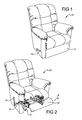
- a leg rest assembly 12 is extensible in an arc of rotation "A" from a stowed position abutting chair 10 (shown in Figure 1 ) to an extended position (shown in Figure 2 ) using a hand lever 14 connected to an actuation mechanism 16.
- hand lever 14 is rotated counterclockwise about an arc of rotation "B" to extend leg rest assembly 12, and can be oppositely rotated to return leg rest assembly 12 from the extended to the stowed position.
- Actuation mechanism 16 and various upholstered frame components can also be assembled as a modular seating unit.
- actuation mechanism 16 and leg rest assembly 12 are not limited to use with chair 10, but are applicable for use in virtually any type of single or multi-person article of furniture.
- the particular structure of the various sub-assemblies and components which, when assembled, define chair 10 are merely intended to illustrate but one furniture application to which the present disclosure is applicable.
- actuation mechanism 16 includes a drive rod 18 integrated into and rotatably supported from a chair frame 19 and, in one aspect, from left and right side frame assemblies 20, 22 defining a drive rod axis of rotation 24.
- Actuation mechanism 16 can further include a front support shaft 25, which together with drive rod 18 are spatially oriented to be located and "suspended" from right and left side frame assemblies 20, 22.
- drive rod 18 is an elongated rectangular-shaped metal shaft having manually-operable hand lever 14 (shown in Figure 1 ) secured thereto proximate an upholstered exterior portion of one of the right or left side frame assemblies 20, 22. Hand lever 14 can therefore be easily reached by an occupant seated in chair 10 for convenient actuation of drive rod 18.
- Mechanism 16 includes a right and a left pantograph linkage 26, 28 and a spring-assisted toggle assembly 30 which are operably associated with drive rod 18 and front support shaft 25 for permitting the seat occupant to selectively actuate leg rest assembly 12 in response to rotation of drive rod 18 via hand lever 14.
- Mechanism 16 can also include right and left support shaft mounting brackets 31, 32, and right and left leg rest support brackets 34, 36.
- chair frame 19 can also include a front rail member 38 which, when interconnected to right and left leg rest support brackets 34, 36, defines rigid "box-like" chair frame 19.
- a first and a second connecting link 40, 41 convert the rotational motion of drive rod 18 to longitudinally translate right and left hand pantograph linkages 26, 28.
- Leg rest assembly 12 is both supported and moved by right and left pantograph linkages 26, 28 and right and left leg rest support brackets 34, 36.
- right and left pantograph linkages 26, 28 are identical.
- Right and left pantograph linkages 26, 28 are suspended about a set of "fixed" suspension points defined by front support shaft 25. The extensible action of leg rest assembly 12 takes place simultaneously for both the right and left pantograph linkages 26, 28 when there is sufficient angular rotation of drive rod 18 via hand lever 14.
- the structural frame components such as side frame assemblies 20, 22 and front rail member 38 are each constructed in a manner which enables them to support springs, padding, upholstery, and the like in order to complete a decorative and stylish chair 10.
- the upholstery shown in Figure 1 can be applied to each outward facing side of side frame assemblies 20, 22 and to a forward facing side 42 of front rail member 38.
- Each frame component is individually preassembled for subsequent modular assembly into chair 10.
- the specific construction shown for each frame component is merely exemplary in nature.
- chair frame 19 can further include a rear rail member 43 which provides additional frame stiffness, an occupant seat support pan or member 44, and at least one occupant back support member 45.
- Mechanism 16 is connected to each of right and left side frame assemblies 20, 22 which in turn can be supported using a spring assembly 46 between a rocker block 47 connected to each of right and left side frame assemblies 20, 22 and a base assembly 48 which is duplicated on the right side of chair 10.
- a front frame member 50 can also be provided to structurally support an area from which front rail member 38 is extensible.
- Mechanism 16 can further include a bracket 52 which is coupled at one end for rotation to drive rod 18 and rotatably coupled at a second end to second connecting link 41.
- a ratcheting member or 3-position leg rest member 54 of the present disclosure is connected to bracket 52 and is adapted to be engaged by an extending member 56 extending from an end 57 of second connecting link 41.
- Mechanism 16 and leg rest assembly 12 in Figure 4 are shown in a stowed position having front rail member 38 and each of right and left pantograph linkages 26, 28 in their fully retracted positions.
- 3-position leg rest member 54 is shown in its connected position with bracket 52.
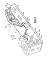
- 3-position leg rest member 54 is coupled to bracket 52 using a first bracket engagement member or first engagement tongue 58 inserted into an aperture 59 of bracket 52, a second bracket engagement member or second engagement tongue 60 in contact with a first surface 62 of bracket 52, and a third engagement member or third engagement tongue 64 located proximate to second engagement tongue 60 but being positioned in contact with an opposite facing second surface 66 with respect to second engagement tongue 60.
- First engagement tongue 58 has a width greater than a width of aperture 59 so that first engagement tongue 58 must be tipped before being slidingly inserted into aperture 59, while the width of aperture 59 permits limited translation of first engagement tongue 58 and therefore 3-position leg rest member 54 to permit a ratchet or ratcheting (elastic back-and-forth) motion of 3-position leg rest member 54.
- the first engagement tongue 58 can be oriented parallel to the bracket second and third engagement tongues 60, 64.
- 3-position leg rest member 54 provides a first member portion defining a free end 68 which is joined by a connecting portion 70 to a second member portion defining a body portion or member body 72.
- Second and third engagement tongues 60, 64 are deflectable with respect to member body 72 using a third member portion defining a spring arm 74. Second and third engagement tongues 60, 64 are homogenously connected to a manual deflection tab 76 which is elastically deflectable to allow connection of second and third engagement tongues 60, 64 to bracket 52 by manually outwardly pressing on manual deflection tab 76 after first engagement tongue 58 is inserted into aperture 59. Free end 68 is elastically deflectable with respect to member body 72 in the installed position.
- Bracket 52 includes a circular drive rod rotation clearance aperture 77 and a drive rod engagement aperture 78 sized and geometrically shaped to slidably receive and engage drive rod 18 shown in Figure 3 .
- Bracket 52 further includes a pin receiving aperture 79 adapted to rotatably fasten bracket 52 to first and second connecting links 40, 41 (an exemplary pinned connection to second connecting link 41 is shown in Figure 4 ).
- 3-position leg rest member 54 is mounted to bracket 52 by first inserting first engagement tongue 58 into aperture 59 of bracket 52.
- Manual deflection tab 76 is then elastically deflected away from bracket 52 in the direction of an arc "Y" to allow second and third engagement tongues 60, 64 to be positioned as shown in contact with first and second surfaces 62, 66 respectively.
- the spring action or biasing force of spring arm 74 when manual deflection tab 76 is deflected provides an elastic return force in the direction of an arc "Z" to hold or retain 3-position leg rest member 54 in the orientation shown.
- 3-position leg rest member 54 is provided as a homogeneous one-piece part made for example from an injection molding process from a polymeric material such as a polyamide material.
- 3-position leg rest member 54 further includes a raised engagement portion 80 and a transition portion 82 which co-extend outwardly from a same side or surface 81 of free end 68.
- a flange 83 defines an end surface oriented substantially parallel to surface 81 and integrally connected with and extending beyond most of the raised engagement portion 80 and at least partially over the transition portion 82.
- Raised engagement portion 80 is positioned proximate to a leading edge 84 of free end 68.
- a stiffening wing member 85 extends outwardly from connecting portion 70 and flange 83 proximate to transition portion 82.
- Each of the connecting portion 70, first, second and third engagement tongues 58, 60, and 64, spring arm 74, and manual deflection tab 76 are homogeneously connected to and integrally made a part of 3-position leg rest member 54.
- 3-position leg rest member 54 further includes a first convex surface 86 extending smoothly from leading edge 84, a concave-shaped slot or first cavity 88, and a second convex surface 90 each created on raised engagement portion 80.
- Transition portion 82 is provided with a concave surface 92 facing raised engagement portion 80.
- a bracket contact face 94 is provided with first engagement tongue 58 which contacts bracket 52 (as shown in Figure 5 ) when first engagement tongue 58 is received in aperture 59.
- a bracket contact wall 96 also homogeneously and transversely extends from a lower-surface 97 of 3-position leg rest member 54, defined as a surface of free end 68 oppositely directed from surface 81 from which raised engagement portion 80 and transition portion 82 extend.
- a radiused junction 98 can be provided between member body 72 and spring arm 74. Radiused junction 98 reduces the potential for the bending stresses at the junction between spring arm 74 and member body 72 to cause stress risers when spring arm 74 is elastically deflected.
- third engagement tongue 64 is positioned proximate to an end face 100 of spring arm 74.
- a first bracket engagement surface 102 is created proximate to and oriented transverse to end face 100 from which third engagement tongue 64 homogeneously extends.
- a second bracket engagement surface 103 is provided on a first engagement tongue 58 facing side of bracket contact wall 96.
- First and second bracket engagement surfaces 102, 103 can be parallel with each other to provide contact with bracket 52 when 3-position leg rest member 54 is mounted on bracket 52.
- 3-position leg rest member 54 can further include an outer wall 104 which smoothly transitions into a concave shaped outer wall 106 of spring arm 74.
- 3-position leg rest member 54 has a total length "C” and a total width "D", a spring arm width "E”, and a connecting portion thickness "F".
- the geometry of 3-position leg rest member 54 can be varied based on the material selected, the amount of spring force required for spring arm 74, and to permit variations in the overall geometry to accommodate use in various mechanisms.
- leg rest assembly 12 including left pantograph linkage 28, left leg rest support bracket 36, and second connecting link 41 is shown rotatably connected to bracket 52 which has one of the 3-position leg rest members 54 connected thereto.
- the stowed position of leg rest assembly 12 is shown in Figure 12 .
- extending member 56 of second connecting link 41 is rotated freely away from and out of contact with 3-position leg rest member 54.
- a pin 108 is provided to rotatably connect bracket 52 with second connecting link 41.
- Drive rod 18 is disposed through bracket 52 including through clearance aperture 77.
- a similar arrangement (not shown) is also provided for the right side components of leg rest assembly 12.
- first extended position of leg rest assembly 12 is shown.
- the first extended position is provided by rotating drive rod 18, which is rotatably coupled to bracket 52 which as previously noted is rotatably coupled to second connecting link 41 by pin 108.
- bracket 52 rotates through an arc of rotation "G" about a longitudinal axis defined through drive rod 18. This rotation initially directs extending member 56 of seconde connecting link 41 into contact with first convex surface 86 of raised engagement portion 80.
- first cavity 88 engages extending member 56 within first cavity 88 provides a retention capability to temporarily provide the first extended position of leg rest assembly 12, and first cavity 88 therefore defines a first stop position for leg rest assembly 12.
- first stop position left leg rest support bracket 36 extends outwardly about a leg rest extension arc "H".
- a second extended position of leg rest assembly 12 is created by further rotation of drive rod 18.
- bracket 52 further rotates about arc of rotation "G”
- extending member 56 is displaced from first cavity 88 and slides along second convex surface 90 once again elastically outwardly deflecting free end 68 and member body 72 of 3-position leg rest member 54 about member deflection arc "J".
- the second extended position is created when extending member 56 is repositioned into a slot or second cavity 110 created between raised engagement portion 80 and transition portion 82.
- the elastic biasing force of spring arm 74 biases 3-position leg rest member 54 about return deflection arc "K" to establish the second extended position of leg rest assembly 12.
- Second cavity 110 therefore defines a second stop position of leg rest assembly 12.
- left leg rest support bracket 36 is further outwardly extended about leg rest extension arc "H".
- leg rest assembly 12 a third or fully extended position of leg rest assembly 12 is shown.
- drive rod 18 has been fully rotated to position bracket 52 substantially parallel with second connecting link 41.
- extending member 56 displaces from second cavity 110 and deflects 3-position leg rest member 54 in member deflection arc "J" as extending member 56 displaces past transition portion 82.
- the fully extended position is achieved when extending member 56 is freely positioned or out of contact with 3-position leg rest member 54, and left leg rest support bracket 36 is fully extended about the leg rest extension arc "H" as shown.
- Extending member 56 contacts a portion of wing member 85 (not shown in this view for clarity) to support the weight of an occupant's legs on leg rest assembly 12 in the fully extended position which defines a third stop position of the leg rest assembly.
- Leg rest assembly 12 can be returned from the fully extended position shown in Figure 15 to the stowed or fully retracted position shown in Figure 12 by rotating drive rod 18 in an opposite rotational direction to return bracket 52 and second connecting link 41 to the position shown in Figure 12 .
- a continuous-wall transition is defined by the continuous wall created by leading edge 84, first convex surface 86, first cavity 88, second convex surface 90, second cavity 110, and concave surface 92.
- the continuous-wall transition reduces friction allowing a smooth sliding motion of extending member 56 over these surfaces between the various stop/extended positions of the leg rest assembly 12.
- a support post 112 provides support for first engagement tongue 58 (not visible in this view).
- Opposed first and second walls 114, 116 are spaced from each other creating a width of first cavity 88 which is greater than a width of extending member 56 allowing extending member 56 to be partially received in first cavity 88.
- a third wall 118 is spaced from concave surface 92 creating a width of second cavity 110 which is also greater than the width of extending member 56 allowing extending member 56 to be partially received in second cavity 110.
- 3-position leg rest member 54 provides a one-piece homogeneous member including first, second, and third portions, the first portion (free end 68) having at least two cavities (first cavity 88 and second cavity 110) each defining a leg rest assembly extended position (first and second extended positions).
- the second portion (member body 72) is connected to the first portion (free end 68) having a male engagement tongue (first engagement tongue 58) extending therefrom.
- the third portion (spring arm 74) is connected to the second portion (member body 72) and has opposed first and second bracket engagement members (second and third engagement tongues 60, 64) spaced from each other.
- the third portion (spring arm 74) is adapted to be elastically deflectable to permit a furniture mechanism bracket (bracket 52) to be received between the first and second bracket engagement members (second and third engagement tongues 60, 64) when the male engagement tongue (first engagement tongue 58) of the second portion (member body 72) is engaged with the furniture member bracket (bracket 52).
- the 3-position leg rest member 54 of the present disclosure provides several advantages. By creating the 3-position leg rest member 54 entirely from a polymeric material, a smooth wall transition or reduced friction operation is created for transitioning between any of the leg rest assembly stowed and extended positions. A polymeric material also reduces a noise level as the extending member 56 contacts or releases from various engagement portions of the 3-position leg rest member 54. Further, a 3-position leg rest member 54 of the present disclosure does not require any additional fasteners to assemble the 3-position leg rest member into its engaged position with bracket 52. This reduces the quantity of parts required for assembly of mechanism 16, eliminates the need to lubricate the assembly, and simplifies the installation because the 3-position leg rest member 54 of the present disclosure defines a snap-on part requiring no installation tools.
Landscapes
- Health & Medical Sciences (AREA)
- Dentistry (AREA)
- General Health & Medical Sciences (AREA)
- Chairs For Special Purposes, Such As Reclining Chairs (AREA)
- Furniture Connections (AREA)
- Passenger Equipment (AREA)
- Legs For Furniture In General (AREA)
Description
- The present disclosure relates to a furniture member leg rest ratcheting member for furniture members including reclining and rocking furniture members.
- The statements in this section merely provide background information related to the present disclosure and may not constitute prior art.
- Traditionally, furniture members such as reclining chairs are equipped with an actuation mechanism which is operatively interconnected between a prefabricated chair frame and a stationary base assembly. The actuation mechanism is typically a combination of various mechanical linkages operable for providing various comfort features such as independent reclining movement of a seat assembly as well as actuation of an extensible leg rest assembly and associated tilting of the chair frame.
- While many conventional reclining furniture members operate satisfactorily, furniture manufacturers are continually striving to develop improved frames and actuation mechanisms for reducing system complexity and smoothness of operation as well as occupant comfort. Furthermore, there is a continuing desire to develop improved fabrication and assembly techniques which will result in reduced costs while promoting increased efficiency and improved product quality.
- In conventional actuation mechanisms, a latching or ratcheting device is provided with the mechanism that allows the leg rest assembly to extend through multiple latched or supported positions for operator comfort. Known latching devices include detent assemblies having multiple sector plates each having multiple arcuate peripheral edges that engage a pin to temporarily latch the leg rest assembly in one of the extended positions. The sector plates can be provided of a metal such as steel or aluminum and are connected using one or more fasteners. To reduce ratcheting noise, the sector assembly commonly includes a compressible element interposed between the sector plates made of a polymeric or rubber material to receive the pin as the pin moves between the various arcuate peripheral edges. The multiple parts of known latching or detent assemblies add to the overall cost and construction complexity of the furniture member.
-
US-A-2007/040439 discloses a furniture member leg rest actuating mechanism adapted to receive an extending portion of a link of a furniture member actuation mechanism for temporarily retaining a leg rest assembly in multiple extended positions. The mechanism includes a one-piece homogeneous member defining first and second positions of the leg rest assembly. - According to the present invention there is provided a furniture member leg rest ratcheting member adapted to receive an extending portion of a link of a furniture member actuation mechanism for temporarily retaining a leg rest assembly in multiple extended positions, comprising:
- a one-piece homogeneous member including:
- a free end having a raised engagement portion including first and second cavities defining first and second stop positions for a leg rest assembly when the extending portion of the link individually enters each of the first and second cavities;
- a deflectable portion homogeneously connected to the free end, the deflectable portion adapted to be elastically deflectable to permit the free end to move in a ratcheting motion when the extending portion of the link moves between the first and second stop positions; and
- a body portion positioned between the free end and the deflectable portion, having a bracket contact wall transversely extending from the body portion.
- Further areas of applicability will become apparent from the description provided herein. It should be understood that the description and specific examples are intended for purposes of illustration only and are not intended to limit the scope of the present disclosure.
- The drawings described herein are for illustration purposes only and are not intended to limit the scope of the present disclosure in any way.
-
Figure 1 is a front perspective view of a furniture member having an extensible leg rest; -
Figure 2 is a front perspective view similar toFigure 1 further showing a furniture member leg rest partially extended; -
Figure 3 is a front perspective view of a partial frame and actuation mechanism for the furniture member ofFigure 1 ; -
Figure 4 is a cross sectional side elevational view of the furniture member operating mechanism ofFigure 3 adapted to provide for an extensible leg rest; -
Figure 5 is a front perspective view of a one piece 3-position member and bracket assembly of the present disclosure; -
Figure 6 is a front perspective view of the one-piece 3-position member ofFigure 5 ; -
Figure 7 is a rear perspective view of the one-piece 3-position member ofFigure 5 ; -
Figure 8 is a bottom perspective view of the one-piece 3-position member ofFigure 5 ; -
Figure 9 is a rotated bottom perspective view of the one-piece 3-position member ofFigure 8 ; -
Figure 10 is a top plan view of the one-piece 3-position member ofFigure 5 ; -
Figure 11 is a side elevational view of the one-piece 3-position member ofFigure 10 ; -
Figure 12 is a side elevational view of an assembly of the one piece 3-position member and bracket assembly ofFigure 5 connected to a left hand pantograph linkage portion of the mechanism ofFigure 3 , shown in a fully retracted position; -
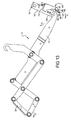
Figure 13 is a side elevational view of the assembly ofFigure 12 shown in a first partially extended position; -
Figure 14 is a side elevational view of the assembly ofFigure 12 shown in a second partially extended position; -
Figure 15 is a side elevational view of the assembly ofFigure 12 shown in a third fully extended position; and -
Figure 16 is a cross sectional top plan view taken atsection 16 ofFigure 11 . - The following description is merely exemplary in nature and is not intended to limit the present disclosure, application, or uses. It should be understood that throughout the drawings, corresponding reference numerals indicate like or corresponding parts and features.
- In accordance with the teachings of the present disclosure, a multiple position leg rest member for use in single and multi-person articles of furniture (i.e.: chairs, sofas and/or loveseats) is disclosed. A general understanding of the art to which the present disclosure pertains is disclosed in
U.S. Patent No. 3,325,210 , Adjustable Leg Rest Locking Device,U.S. Patent No. 5,570,927 , Modular Wall Proximity Reclining Chair, andU.S. Patent No. 6,655,732 , Multiple Position Leg Rest Mechanism For A Reclining Chair, which are commonly owned by the assignee of the present mechanism. As will be described, the pre-assembled actuation mechanism permits a leg rest assembly to pivot in a 3-position movement from upholstered frame components so as to provide precise mechanical alignment and superior structural rigidity while concomitantly facilitating application of highly efficient fabrication and assembly processes. - The term "homogeneous" as used herein is defined as a part, component, member, or the like (collectively the part) having all portions of the part formed of the same material and by the same process used to create the part, such as by molding including injection molding, or casting, such that no portion(s) of the part require connection to any other portion by a secondary process including but not limited to welding, adhesive bonding, mechanical connection, second molding or casting process, or the like, and the chemical properties of the part material are substantially equivalent throughout the part.
- With reference to
Figures 1 and 2 , the article of furniture shown is a combination wall proximity recliner and tilt chair, hereinafter referred to as achair 10. Aleg rest assembly 12 is extensible in an arc of rotation "A" from a stowed position abutting chair 10 (shown inFigure 1 ) to an extended position (shown inFigure 2 ) using ahand lever 14 connected to anactuation mechanism 16. In one aspect of the disclosure,hand lever 14 is rotated counterclockwise about an arc of rotation "B" to extendleg rest assembly 12, and can be oppositely rotated to returnleg rest assembly 12 from the extended to the stowed position.Actuation mechanism 16 and various upholstered frame components can also be assembled as a modular seating unit. It should be understood that the elements ofactuation mechanism 16 andleg rest assembly 12 are not limited to use withchair 10, but are applicable for use in virtually any type of single or multi-person article of furniture. As such, the particular structure of the various sub-assemblies and components which, when assembled, definechair 10 are merely intended to illustrate but one furniture application to which the present disclosure is applicable. - Referring now generally to
Figure 3 and again toFigure 1 ,actuation mechanism 16 includes adrive rod 18 integrated into and rotatably supported from achair frame 19 and, in one aspect, from left and rightside frame assemblies rotation 24.Actuation mechanism 16 can further include afront support shaft 25, which together withdrive rod 18 are spatially oriented to be located and "suspended" from right and leftside frame assemblies drive rod 18 is an elongated rectangular-shaped metal shaft having manually-operable hand lever 14 (shown inFigure 1 ) secured thereto proximate an upholstered exterior portion of one of the right or leftside frame assemblies Hand lever 14 can therefore be easily reached by an occupant seated inchair 10 for convenient actuation ofdrive rod 18. -
Leg rest assembly 12 is supported for extensible movement usingactuation mechanism 16. More specifically,mechanism 16 includes a right and aleft pantograph linkage toggle assembly 30 which are operably associated withdrive rod 18 andfront support shaft 25 for permitting the seat occupant to selectively actuateleg rest assembly 12 in response to rotation ofdrive rod 18 viahand lever 14.Mechanism 16 can also include right and left supportshaft mounting brackets rest support brackets side frame assemblies chair frame 19 can also include afront rail member 38 which, when interconnected to right and left legrest support brackets chair frame 19. - A first and a second connecting
link drive rod 18 to longitudinally translate right and lefthand pantograph linkages Leg rest assembly 12 is both supported and moved by right andleft pantograph linkages rest support brackets left pantograph linkages pantograph linkages front support shaft 25. The extensible action ofleg rest assembly 12 takes place simultaneously for both the right and leftpantograph linkages drive rod 18 viahand lever 14. - In general, the structural frame components such as
side frame assemblies front rail member 38 are each constructed in a manner which enables them to support springs, padding, upholstery, and the like in order to complete a decorative andstylish chair 10. For example, the upholstery shown inFigure 1 can be applied to each outward facing side ofside frame assemblies side 42 offront rail member 38. Each frame component is individually preassembled for subsequent modular assembly intochair 10. However, it is to be understood that the specific construction shown for each frame component is merely exemplary in nature. - With specific reference to
Figure 4 ,chair frame 19 can further include arear rail member 43 which provides additional frame stiffness, an occupant seat support pan ormember 44, and at least one occupant backsupport member 45.Mechanism 16 is connected to each of right and leftside frame assemblies spring assembly 46 between arocker block 47 connected to each of right and leftside frame assemblies base assembly 48 which is duplicated on the right side ofchair 10. Afront frame member 50 can also be provided to structurally support an area from whichfront rail member 38 is extensible. -
Mechanism 16 can further include abracket 52 which is coupled at one end for rotation to driverod 18 and rotatably coupled at a second end to second connectinglink 41. A ratcheting member or 3-positionleg rest member 54 of the present disclosure is connected tobracket 52 and is adapted to be engaged by an extendingmember 56 extending from anend 57 of second connectinglink 41.Mechanism 16 andleg rest assembly 12 inFigure 4 are shown in a stowed position havingfront rail member 38 and each of right and leftpantograph linkages - Referring to
Figure 5 , 3-positionleg rest member 54 is shown in its connected position withbracket 52. 3-positionleg rest member 54 is coupled tobracket 52 using a first bracket engagement member orfirst engagement tongue 58 inserted into anaperture 59 ofbracket 52, a second bracket engagement member orsecond engagement tongue 60 in contact with afirst surface 62 ofbracket 52, and a third engagement member orthird engagement tongue 64 located proximate tosecond engagement tongue 60 but being positioned in contact with an opposite facingsecond surface 66 with respect tosecond engagement tongue 60.First engagement tongue 58 has a width greater than a width ofaperture 59 so thatfirst engagement tongue 58 must be tipped before being slidingly inserted intoaperture 59, while the width ofaperture 59 permits limited translation offirst engagement tongue 58 and therefore 3-positionleg rest member 54 to permit a ratchet or ratcheting (elastic back-and-forth) motion of 3-positionleg rest member 54. Thefirst engagement tongue 58 can be oriented parallel to the bracket second andthird engagement tongues leg rest member 54 provides a first member portion defining afree end 68 which is joined by a connectingportion 70 to a second member portion defining a body portion ormember body 72. Second andthird engagement tongues member body 72 using a third member portion defining aspring arm 74. Second andthird engagement tongues manual deflection tab 76 which is elastically deflectable to allow connection of second andthird engagement tongues bracket 52 by manually outwardly pressing onmanual deflection tab 76 afterfirst engagement tongue 58 is inserted intoaperture 59.Free end 68 is elastically deflectable with respect tomember body 72 in the installed position. -
Bracket 52 includes a circular drive rodrotation clearance aperture 77 and a driverod engagement aperture 78 sized and geometrically shaped to slidably receive and engagedrive rod 18 shown inFigure 3 .Bracket 52 further includes apin receiving aperture 79 adapted to rotatably fastenbracket 52 to first and second connectinglinks 40, 41 (an exemplary pinned connection to second connectinglink 41 is shown inFigure 4 ). 3-positionleg rest member 54 is mounted tobracket 52 by first insertingfirst engagement tongue 58 intoaperture 59 ofbracket 52.Manual deflection tab 76 is then elastically deflected away frombracket 52 in the direction of an arc "Y" to allow second andthird engagement tongues second surfaces spring arm 74 whenmanual deflection tab 76 is deflected provides an elastic return force in the direction of an arc "Z" to hold or retain 3-positionleg rest member 54 in the orientation shown. - Referring to
Figure 6 , 3-positionleg rest member 54 is provided as a homogeneous one-piece part made for example from an injection molding process from a polymeric material such as a polyamide material. 3-positionleg rest member 54 further includes a raisedengagement portion 80 and atransition portion 82 which co-extend outwardly from a same side orsurface 81 offree end 68. Aflange 83 defines an end surface oriented substantially parallel to surface 81 and integrally connected with and extending beyond most of the raisedengagement portion 80 and at least partially over thetransition portion 82. Raisedengagement portion 80 is positioned proximate to aleading edge 84 offree end 68. A stiffeningwing member 85 extends outwardly from connectingportion 70 andflange 83 proximate to transitionportion 82. Each of the connectingportion 70, first, second andthird engagement tongues spring arm 74, andmanual deflection tab 76 are homogeneously connected to and integrally made a part of 3-positionleg rest member 54. - Referring to
Figure 7 and again toFigure 4 , 3-positionleg rest member 54 further includes a firstconvex surface 86 extending smoothly from leadingedge 84, a concave-shaped slot orfirst cavity 88, and a secondconvex surface 90 each created on raisedengagement portion 80.Transition portion 82 is provided with aconcave surface 92 facing raisedengagement portion 80. Each of these features are adapted to receive or be contacted by extendingmember 56 of either first or second connectinglinks Figures 12 through 15 . - Referring now to
Figure 8 and again toFigures 5 and6 , abracket contact face 94 is provided withfirst engagement tongue 58 which contacts bracket 52 (as shown inFigure 5 ) whenfirst engagement tongue 58 is received inaperture 59. Abracket contact wall 96 also homogeneously and transversely extends from a lower-surface 97 of 3-positionleg rest member 54, defined as a surface offree end 68 oppositely directed fromsurface 81 from which raisedengagement portion 80 andtransition portion 82 extend. Aradiused junction 98 can be provided betweenmember body 72 andspring arm 74.Radiused junction 98 reduces the potential for the bending stresses at the junction betweenspring arm 74 andmember body 72 to cause stress risers whenspring arm 74 is elastically deflected. - Referring to
Figure 9 and again toFigure 5 ,third engagement tongue 64 is positioned proximate to anend face 100 ofspring arm 74. A firstbracket engagement surface 102 is created proximate to and oriented transverse to endface 100 from whichthird engagement tongue 64 homogeneously extends. A secondbracket engagement surface 103 is provided on afirst engagement tongue 58 facing side ofbracket contact wall 96. First and second bracket engagement surfaces 102, 103 can be parallel with each other to provide contact withbracket 52 when 3-positionleg rest member 54 is mounted onbracket 52. - Referring to
Figures 10 and 11 , 3-positionleg rest member 54 can further include anouter wall 104 which smoothly transitions into a concave shapedouter wall 106 ofspring arm 74. 3-positionleg rest member 54 has a total length "C" and a total width "D", a spring arm width "E", and a connecting portion thickness "F". The geometry of 3-positionleg rest member 54 can be varied based on the material selected, the amount of spring force required forspring arm 74, and to permit variations in the overall geometry to accommodate use in various mechanisms. - Referring to
Figure 12 , a portion ofleg rest assembly 12 includingleft pantograph linkage 28, left legrest support bracket 36, and second connectinglink 41 is shown rotatably connected tobracket 52 which has one of the 3-positionleg rest members 54 connected thereto. The stowed position ofleg rest assembly 12 is shown inFigure 12 . In the stowed position, extendingmember 56 of second connectinglink 41 is rotated freely away from and out of contact with 3-positionleg rest member 54. Apin 108 is provided to rotatably connectbracket 52 with second connectinglink 41. Driverod 18 is disposed throughbracket 52 including throughclearance aperture 77. A similar arrangement (not shown) is also provided for the right side components ofleg rest assembly 12. - Referring to
Figure 13 and again toFigures 5 and6 , a first extended position ofleg rest assembly 12 is shown. The first extended position is provided by rotatingdrive rod 18, which is rotatably coupled tobracket 52 which as previously noted is rotatably coupled to second connectinglink 41 bypin 108. Whendrive rod 18 is rotated,bracket 52 rotates through an arc of rotation "G" about a longitudinal axis defined throughdrive rod 18. This rotation initially directs extendingmember 56 ofseconde connecting link 41 into contact with firstconvex surface 86 of raisedengagement portion 80. Contact between extendingmember 56 and firstconvex surface 86 causes elastic deflection offree end 68 andmember body 72 through bending ofspring arm 74 of 3-positionleg rest member 54 permitting displacement about a member deflection arc "J" until extendingmember 56 snaps intofirst cavity 88. When extendingmember 56 is positioned proximate tofirst cavity 88, the elastic biasing force ofspring arm 74 biases 3-positionleg rest member 54 to elastically return in a return deflection arc "K". This back-and-forth or ratcheting motion offree end 68 andmember body 72 by deflection ofspring arm 74 is provided by the elastic biasing capability ofspring arm 74 and the sliding clearance offirst engagement tongue 58 withinaperture 59 ofbracket 52. Engagement of extendingmember 56 withinfirst cavity 88 provides a retention capability to temporarily provide the first extended position ofleg rest assembly 12, andfirst cavity 88 therefore defines a first stop position forleg rest assembly 12. In the first stop position left legrest support bracket 36 extends outwardly about a leg rest extension arc "H". - Referring to
Figure 14 and again toFigure 5 , a second extended position ofleg rest assembly 12 is created by further rotation ofdrive rod 18. Asbracket 52 further rotates about arc of rotation "G", extendingmember 56 is displaced fromfirst cavity 88 and slides along secondconvex surface 90 once again elastically outwardly deflectingfree end 68 andmember body 72 of 3-positionleg rest member 54 about member deflection arc "J". The second extended position is created when extendingmember 56 is repositioned into a slot orsecond cavity 110 created between raisedengagement portion 80 andtransition portion 82. At this time, the elastic biasing force ofspring arm 74 biases 3-positionleg rest member 54 about return deflection arc "K" to establish the second extended position ofleg rest assembly 12.Second cavity 110 therefore defines a second stop position ofleg rest assembly 12. At the second stop position, left legrest support bracket 36 is further outwardly extended about leg rest extension arc "H". - Referring to
Figure 15 and again toFigures 5 and6 , a third or fully extended position ofleg rest assembly 12 is shown. In the fully extended position, driverod 18 has been fully rotated to positionbracket 52 substantially parallel with second connectinglink 41. During this rotation, extendingmember 56 displaces fromsecond cavity 110 and deflects 3-positionleg rest member 54 in member deflection arc "J" as extendingmember 56 displacespast transition portion 82. The fully extended position is achieved when extendingmember 56 is freely positioned or out of contact with 3-positionleg rest member 54, and left legrest support bracket 36 is fully extended about the leg rest extension arc "H" as shown. Extendingmember 56 contacts a portion of wing member 85 (not shown in this view for clarity) to support the weight of an occupant's legs onleg rest assembly 12 in the fully extended position which defines a third stop position of the leg rest assembly.Leg rest assembly 12 can be returned from the fully extended position shown inFigure 15 to the stowed or fully retracted position shown inFigure 12 by rotatingdrive rod 18 in an opposite rotational direction to returnbracket 52 and second connectinglink 41 to the position shown inFigure 12 . - Referring to
Figure 16 and again toFigures 13-15 , a continuous-wall transition is defined by the continuous wall created by leadingedge 84, firstconvex surface 86,first cavity 88, secondconvex surface 90,second cavity 110, andconcave surface 92. The continuous-wall transition reduces friction allowing a smooth sliding motion of extendingmember 56 over these surfaces between the various stop/extended positions of theleg rest assembly 12. Asupport post 112 provides support for first engagement tongue 58 (not visible in this view). Opposed first andsecond walls first cavity 88 which is greater than a width of extendingmember 56 allowing extendingmember 56 to be partially received infirst cavity 88. Similarly, athird wall 118 is spaced fromconcave surface 92 creating a width ofsecond cavity 110 which is also greater than the width of extendingmember 56 allowing extendingmember 56 to be partially received insecond cavity 110. - 3-position
leg rest member 54 provides a one-piece homogeneous member including first, second, and third portions, the first portion (free end 68) having at least two cavities (first cavity 88 and second cavity 110) each defining a leg rest assembly extended position (first and second extended positions). The second portion (member body 72) is connected to the first portion (free end 68) having a male engagement tongue (first engagement tongue 58) extending therefrom. The third portion (spring arm 74) is connected to the second portion (member body 72) and has opposed first and second bracket engagement members (second andthird engagement tongues 60, 64) spaced from each other. The third portion (spring arm 74) is adapted to be elastically deflectable to permit a furniture mechanism bracket (bracket 52) to be received between the first and second bracket engagement members (second andthird engagement tongues 60, 64) when the male engagement tongue (first engagement tongue 58) of the second portion (member body 72) is engaged with the furniture member bracket (bracket 52). - The 3-position
leg rest member 54 of the present disclosure provides several advantages. By creating the 3-positionleg rest member 54 entirely from a polymeric material, a smooth wall transition or reduced friction operation is created for transitioning between any of the leg rest assembly stowed and extended positions. A polymeric material also reduces a noise level as the extendingmember 56 contacts or releases from various engagement portions of the 3-positionleg rest member 54. Further, a 3-positionleg rest member 54 of the present disclosure does not require any additional fasteners to assemble the 3-position leg rest member into its engaged position withbracket 52. This reduces the quantity of parts required for assembly ofmechanism 16, eliminates the need to lubricate the assembly, and simplifies the installation because the 3-positionleg rest member 54 of the present disclosure defines a snap-on part requiring no installation tools.
Claims (6)
- A furniture member leg rest ratcheting member (54) adapted to receive an extending portion (56) of a link (41) of a furniture member actuation mechanism (16) for temporarily retaining a leg rest assembly (12) in multiple extended positions, comprising:a one-piece homogeneous member including:a free end (68) having a raised engagement portion (80) including first and second cavities (88, 110) defining first and second stop positions for the leg rest assembly when the extending portion of the link individually enters each of the first and second cavities,characterised in that the one-piece homogeneous member further includes:a deflectable portion (74) homogeneously connected to the free end, the deflectable portion being elastically deflectable to permit the free end to move in a ratcheting motion when the extending portion of the link moves between the first and second stop positions; anda body portion (72) positioned between the free end and the deflectable portion, having a bracket contact wall (96) transversely extending from the body portion.
- The furniture member leg rest ratcheting member (54) of claim 1, wherein the body portion (72) further includes a support post (112) having a male engagement tongue (58) extending from the support post, the engagement tongue and the support post spatially separated from the bracket contact wall (96).
- The furniture member leg rest ratcheting member (54) of Claim 1, wherein the one-piece homogeneous member further includes a wing (85) which when contacted by the extending portion (56) of the link (41) defines a third stop position of the leg rest assembly (12).
- The furniture member leg rest ratcheting member (54) of Claim 1, wherein the one-piece homogeneous member further includes a flange (83) in integral contact with and at least partially covering the raised engagement portion (80) and a transition portion (82).
- The furniture member leg rest ratcheting member (54) of Claim 1, wherein the one-piece homogeneous member further includes:a leading edge (84) of the raised engagement portion (80); anda convex surface (86) defining a transition between the leading edge and the first cavity (88).
- The furniture member leg rest ratcheting member (54) of Claim 1, wherein the raised engagement portion (80) includes a continuous-wall transition defined by a leading edge (84), a first convex surface (86), the first cavity (88), a second convex surface (90), the second cavity (110) and a third convex surface.
Priority Applications (3)
| Application Number | Priority Date | Filing Date | Title |
|---|---|---|---|
| PL14165894T PL2759229T3 (en) | 2009-01-08 | 2009-12-28 | One-piece 3-position leg rest member for furniture member |
| DK14165894.8T DK2759229T3 (en) | 2009-01-08 | 2009-12-28 | One-piece leg support with 3 positions for a furniture element |
| EP14165894.8A EP2759229B1 (en) | 2009-01-08 | 2009-12-28 | One-piece 3-position leg rest member for furniture member |
Applications Claiming Priority (2)
| Application Number | Priority Date | Filing Date | Title |
|---|---|---|---|
| US12/350,414 US8132855B2 (en) | 2009-01-08 | 2009-01-08 | One-piece 3-position leg rest member for furniture member |
| PCT/US2009/069558 WO2010080671A2 (en) | 2009-01-08 | 2009-12-28 | One-piece 3-position leg rest member for furniture member |
Related Child Applications (2)
| Application Number | Title | Priority Date | Filing Date |
|---|---|---|---|
| EP14165894.8A Division EP2759229B1 (en) | 2009-01-08 | 2009-12-28 | One-piece 3-position leg rest member for furniture member |
| EP14165894.8A Division-Into EP2759229B1 (en) | 2009-01-08 | 2009-12-28 | One-piece 3-position leg rest member for furniture member |
Publications (3)
| Publication Number | Publication Date |
|---|---|
| EP2384131A2 EP2384131A2 (en) | 2011-11-09 |
| EP2384131A4 EP2384131A4 (en) | 2014-01-22 |
| EP2384131B1 true EP2384131B1 (en) | 2015-02-18 |
Family
ID=42311216
Family Applications (2)
| Application Number | Title | Priority Date | Filing Date |
|---|---|---|---|
| EP14165894.8A Active EP2759229B1 (en) | 2009-01-08 | 2009-12-28 | One-piece 3-position leg rest member for furniture member |
| EP20090838021 Active EP2384131B1 (en) | 2009-01-08 | 2009-12-28 | One-piece leg rest member for furniture member |
Family Applications Before (1)
| Application Number | Title | Priority Date | Filing Date |
|---|---|---|---|
| EP14165894.8A Active EP2759229B1 (en) | 2009-01-08 | 2009-12-28 | One-piece 3-position leg rest member for furniture member |
Country Status (11)
| Country | Link |
|---|---|
| US (1) | US8132855B2 (en) |
| EP (2) | EP2759229B1 (en) |
| CN (1) | CN102271553B (en) |
| DK (1) | DK2759229T3 (en) |
| ES (1) | ES2544647T3 (en) |
| HU (1) | HUE027732T2 (en) |
| PL (1) | PL2759229T3 (en) |
| PT (1) | PT2759229E (en) |
| RU (1) | RU2498754C2 (en) |
| TW (1) | TWI452980B (en) |
| WO (1) | WO2010080671A2 (en) |
Families Citing this family (19)
| Publication number | Priority date | Publication date | Assignee | Title |
|---|---|---|---|---|
| DE102013208562A1 (en) * | 2013-05-08 | 2014-11-13 | Kintec-Solution Gmbh | Seating furniture structure and seating |
| US8926009B1 (en) | 2013-07-23 | 2015-01-06 | La-Z-Boy Incorporated | Covered leg rest linkage for furniture member |
| US9101221B2 (en) | 2013-07-23 | 2015-08-11 | La-Z-Boy Incorporated | Furniture member with center support leg rest |
| US10092106B2 (en) | 2015-07-14 | 2018-10-09 | La-Z-Boy Incorporated | Recliner and legrest mechanism for a furniture member |
| US9986832B2 (en) * | 2016-06-06 | 2018-06-05 | La-Z-Boy Incorporated | Furniture member with wall-proximity mechanism |
| US9986835B2 (en) | 2016-09-22 | 2018-06-05 | La-Z-Boy Incorporated | Furniture member having cam tilt mechanism |
| TWI738969B (en) * | 2017-02-13 | 2021-09-11 | 日商小糸電工股份有限公司 | Seating device |
| US10568428B2 (en) | 2017-04-07 | 2020-02-25 | La-Z-Boy Incorporated | Furniture member having flexible seatback |
| US10537178B2 (en) | 2017-04-07 | 2020-01-21 | La-Z-Boy Incorporated | Furniture member having flexible seatback |
| US10349748B2 (en) * | 2017-08-11 | 2019-07-16 | Ashley Furniture Industries, Inc. | Torsion activator for motion furniture |
| US10524575B2 (en) | 2018-04-16 | 2020-01-07 | La-Z-Boy Incorporated | Furniture member with foldable pawl and ratchet assembly |
| US10820708B2 (en) | 2018-05-18 | 2020-11-03 | La-Z-Boy Incorporated | Furniture member with wall-proximity mechanism and locking trigger |
| US10524574B2 (en) | 2018-05-18 | 2020-01-07 | La-Z-Boy Incorporated | Furniture member with powered wall-proximity mechanism |
| JP7225812B2 (en) * | 2019-01-16 | 2023-02-21 | トヨタ紡織株式会社 | vehicle seat |
| US11134778B2 (en) | 2019-05-09 | 2021-10-05 | La-Z-Boy Incorporated | Reclining chaise |
| US11197549B1 (en) | 2020-09-28 | 2021-12-14 | La-Z-Boy Incorporated | Wall-proximity furniture member having sync mechanism |
| US12478185B2 (en) | 2022-03-18 | 2025-11-25 | La-Z-Boy Incorporated | Reclining chaise mechanism |
| US12622521B2 (en) | 2022-12-05 | 2026-05-12 | La-Z-Boy Incorporated | Rocking and reclining wall proximity furniture member |
| US12588765B2 (en) | 2023-05-04 | 2026-03-31 | La-Z-Boy Incorporated | Rocking furniture member with power synchronous mechanism |
Family Cites Families (14)
| Publication number | Priority date | Publication date | Assignee | Title |
|---|---|---|---|---|
| US3325210A (en) * | 1965-10-23 | 1967-06-13 | La Z Boy Chair Co | Adjustable leg rest locking device |
| GB2085293B (en) * | 1980-09-16 | 1985-03-06 | La Z Boy Chair Co | Improved reclining chair |
| US4844536A (en) * | 1986-10-10 | 1989-07-04 | Mizelle Ned W | Extensible legrest mechanism for furniture seating units |
| SU1581264A1 (en) * | 1988-08-08 | 1990-07-30 | Производственное Объединение "Ворошиловградский Тепловозостроительный Завод Им.Октябрьской Революции" | Rest arm-chair |
| US5570927A (en) * | 1991-10-11 | 1996-11-05 | La-Z-Boy Chair Company | Modular wall proximity reclining chair |
| US5397168A (en) * | 1993-09-02 | 1995-03-14 | Bemis Manufacturing Company | Chair with adjustable backrest |
| KR970005765B1 (en) * | 1993-09-28 | 1997-04-19 | 엘지전자 주식회사 | Diffraction yoke stopper for cathode ray tube |
| US5855030A (en) * | 1996-09-11 | 1999-01-05 | Hickory Springs Manufacturing Co. | Folding sofa bed frame structure with two-position TV headrest |
| JP4067347B2 (en) | 2002-06-27 | 2008-03-26 | 株式会社イトーキ | Chair |
| US6655732B1 (en) * | 2002-07-16 | 2003-12-02 | La-Z-Boy Incorporated | Multiple position leg rest mechanism for a reclining chair |
| US7017992B2 (en) * | 2003-02-18 | 2006-03-28 | Warvel Products, Inc.-N.C. | Chair control device for a tiltable chair |
| US6896323B2 (en) * | 2003-06-20 | 2005-05-24 | La-Z-Boy Incorporated | Actuation mechanism for reclining chair |
| US7338132B2 (en) * | 2005-08-16 | 2008-03-04 | La-Z-Boy Incorporated | Multiple position leg rest mechanism |
| US7585018B2 (en) * | 2006-01-10 | 2009-09-08 | La-Z-Boy Incorporated | Wall proximity reclining chair with in-line linkage mechanism |
-
2009
- 2009-01-08 US US12/350,414 patent/US8132855B2/en active Active
- 2009-12-24 TW TW98144686A patent/TWI452980B/en active
- 2009-12-28 CN CN2009801540589A patent/CN102271553B/en active Active
- 2009-12-28 WO PCT/US2009/069558 patent/WO2010080671A2/en not_active Ceased
- 2009-12-28 EP EP14165894.8A patent/EP2759229B1/en active Active
- 2009-12-28 ES ES14165894.8T patent/ES2544647T3/en active Active
- 2009-12-28 DK DK14165894.8T patent/DK2759229T3/en active
- 2009-12-28 PL PL14165894T patent/PL2759229T3/en unknown
- 2009-12-28 RU RU2011133054/12A patent/RU2498754C2/en not_active IP Right Cessation
- 2009-12-28 EP EP20090838021 patent/EP2384131B1/en active Active
- 2009-12-28 PT PT141658948T patent/PT2759229E/en unknown
- 2009-12-28 HU HUE14165894A patent/HUE027732T2/en unknown
Also Published As
| Publication number | Publication date |
|---|---|
| PT2759229E (en) | 2015-10-07 |
| HUE027732T2 (en) | 2016-10-28 |
| WO2010080671A2 (en) | 2010-07-15 |
| RU2498754C2 (en) | 2013-11-20 |
| ES2544647T3 (en) | 2015-09-02 |
| WO2010080671A3 (en) | 2010-10-21 |
| EP2384131A4 (en) | 2014-01-22 |
| EP2759229A1 (en) | 2014-07-30 |
| EP2759229B1 (en) | 2015-06-17 |
| CN102271553B (en) | 2013-09-11 |
| US20100171355A1 (en) | 2010-07-08 |
| DK2759229T3 (en) | 2015-07-20 |
| PL2759229T3 (en) | 2015-12-31 |
| TWI452980B (en) | 2014-09-21 |
| US8132855B2 (en) | 2012-03-13 |
| TW201032757A (en) | 2010-09-16 |
| EP2384131A2 (en) | 2011-11-09 |
| RU2011133054A (en) | 2013-02-20 |
| CN102271553A (en) | 2011-12-07 |
Similar Documents
| Publication | Publication Date | Title |
|---|---|---|
| EP2759229B1 (en) | One-piece 3-position leg rest member for furniture member | |
| US10820708B2 (en) | Furniture member with wall-proximity mechanism and locking trigger | |
| US7926879B2 (en) | Load support structure | |
| CN101553151B (en) | Multi-position leg rest mechanism | |
| CN101511231B (en) | Furniture mechanism with tilt cam for multiple position tilt | |
| US7971934B2 (en) | Lumbar support system for furniture member | |
| EP0638266B1 (en) | Dual leg rest assembly | |
| JPH06343528A (en) | Two-way high leg recliner | |
| US20060290174A1 (en) | Rocking-reclining seating unit with motion lock | |
| WO2007022191A2 (en) | Foldable pawl and ratchet assembly | |
| US20090033129A1 (en) | Snap-On Leg Rest Mechanism For Furniture Member | |
| JPH11253263A (en) | Chair synchro locking device | |
| JP2003325261A (en) | Chair synchro locking device | |
| CN223025688U (en) | Seating unit and furniture assembly | |
| CN119655586A (en) | Armrest floor-type seating unit and furniture assembly | |
| KR200230974Y1 (en) | Slider of a seat for the car | |
| JP2026076760A (en) | chair | |
| JPH10179328A (en) | Arm-rest of relaxation chair | |
| HK1137631B (en) | Multiple position leg rest mechanism | |
| HK1128599A1 (en) | Rocking reclining chair |
Legal Events
| Date | Code | Title | Description |
|---|---|---|---|
| PUAI | Public reference made under article 153(3) epc to a published international application that has entered the european phase |
Free format text: ORIGINAL CODE: 0009012 |
|
| 17P | Request for examination filed |
Effective date: 20110801 |
|
| AK | Designated contracting states |
Kind code of ref document: A2 Designated state(s): AT BE BG CH CY CZ DE DK EE ES FI FR GB GR HR HU IE IS IT LI LT LU LV MC MK MT NL NO PL PT RO SE SI SK SM TR |
|
| DAX | Request for extension of the european patent (deleted) | ||
| A4 | Supplementary search report drawn up and despatched |
Effective date: 20131220 |
|
| RIC1 | Information provided on ipc code assigned before grant |
Ipc: A47C 7/50 20060101ALI20131216BHEP Ipc: A47C 1/034 20060101ALI20131216BHEP Ipc: A47C 1/022 20060101AFI20131216BHEP |
|
| REG | Reference to a national code |
Ref country code: DE Ref legal event code: R079 Ref document number: 602009029473 Country of ref document: DE Free format text: PREVIOUS MAIN CLASS: A47C0001022000 Ipc: A47C0001034000 |
|
| GRAP | Despatch of communication of intention to grant a patent |
Free format text: ORIGINAL CODE: EPIDOSNIGR1 |
|
| RIC1 | Information provided on ipc code assigned before grant |
Ipc: A47C 7/50 20060101ALI20140616BHEP Ipc: A47C 1/035 20060101ALI20140616BHEP Ipc: A47C 1/034 20060101AFI20140616BHEP |
|
| INTG | Intention to grant announced |
Effective date: 20140714 |
|
| GRAS | Grant fee paid |
Free format text: ORIGINAL CODE: EPIDOSNIGR3 |
|
| GRAA | (expected) grant |
Free format text: ORIGINAL CODE: 0009210 |
|
| AK | Designated contracting states |
Kind code of ref document: B1 Designated state(s): AT BE BG CH CY CZ DE DK EE ES FI FR GB GR HR HU IE IS IT LI LT LU LV MC MK MT NL NO PL PT RO SE SI SK SM TR |
|
| REG | Reference to a national code |
Ref country code: GB Ref legal event code: FG4D |
|
| REG | Reference to a national code |
Ref country code: CH Ref legal event code: EP |
|
| REG | Reference to a national code |
Ref country code: AT Ref legal event code: REF Ref document number: 710316 Country of ref document: AT Kind code of ref document: T Effective date: 20150315 |
|
| REG | Reference to a national code |
Ref country code: IE Ref legal event code: FG4D |
|
| REG | Reference to a national code |
Ref country code: DE Ref legal event code: R096 Ref document number: 602009029473 Country of ref document: DE Effective date: 20150402 |
|
| REG | Reference to a national code |
Ref country code: NL Ref legal event code: VDEP Effective date: 20150218 |
|
| REG | Reference to a national code |
Ref country code: AT Ref legal event code: MK05 Ref document number: 710316 Country of ref document: AT Kind code of ref document: T Effective date: 20150218 |
|
| REG | Reference to a national code |
Ref country code: LT Ref legal event code: MG4D |
|
| PG25 | Lapsed in a contracting state [announced via postgrant information from national office to epo] |
Ref country code: NO Free format text: LAPSE BECAUSE OF FAILURE TO SUBMIT A TRANSLATION OF THE DESCRIPTION OR TO PAY THE FEE WITHIN THE PRESCRIBED TIME-LIMIT Effective date: 20150518 Ref country code: HR Free format text: LAPSE BECAUSE OF FAILURE TO SUBMIT A TRANSLATION OF THE DESCRIPTION OR TO PAY THE FEE WITHIN THE PRESCRIBED TIME-LIMIT Effective date: 20150218 Ref country code: SE Free format text: LAPSE BECAUSE OF FAILURE TO SUBMIT A TRANSLATION OF THE DESCRIPTION OR TO PAY THE FEE WITHIN THE PRESCRIBED TIME-LIMIT Effective date: 20150218 Ref country code: LT Free format text: LAPSE BECAUSE OF FAILURE TO SUBMIT A TRANSLATION OF THE DESCRIPTION OR TO PAY THE FEE WITHIN THE PRESCRIBED TIME-LIMIT Effective date: 20150218 Ref country code: FI Free format text: LAPSE BECAUSE OF FAILURE TO SUBMIT A TRANSLATION OF THE DESCRIPTION OR TO PAY THE FEE WITHIN THE PRESCRIBED TIME-LIMIT Effective date: 20150218 Ref country code: ES Free format text: LAPSE BECAUSE OF FAILURE TO SUBMIT A TRANSLATION OF THE DESCRIPTION OR TO PAY THE FEE WITHIN THE PRESCRIBED TIME-LIMIT Effective date: 20150218 |
|
| PG25 | Lapsed in a contracting state [announced via postgrant information from national office to epo] |
Ref country code: AT Free format text: LAPSE BECAUSE OF FAILURE TO SUBMIT A TRANSLATION OF THE DESCRIPTION OR TO PAY THE FEE WITHIN THE PRESCRIBED TIME-LIMIT Effective date: 20150218 Ref country code: NL Free format text: LAPSE BECAUSE OF FAILURE TO SUBMIT A TRANSLATION OF THE DESCRIPTION OR TO PAY THE FEE WITHIN THE PRESCRIBED TIME-LIMIT Effective date: 20150218 Ref country code: LV Free format text: LAPSE BECAUSE OF FAILURE TO SUBMIT A TRANSLATION OF THE DESCRIPTION OR TO PAY THE FEE WITHIN THE PRESCRIBED TIME-LIMIT Effective date: 20150218 Ref country code: GR Free format text: LAPSE BECAUSE OF FAILURE TO SUBMIT A TRANSLATION OF THE DESCRIPTION OR TO PAY THE FEE WITHIN THE PRESCRIBED TIME-LIMIT Effective date: 20150519 Ref country code: IS Free format text: LAPSE BECAUSE OF FAILURE TO SUBMIT A TRANSLATION OF THE DESCRIPTION OR TO PAY THE FEE WITHIN THE PRESCRIBED TIME-LIMIT Effective date: 20150618 |
|
| PG25 | Lapsed in a contracting state [announced via postgrant information from national office to epo] |
Ref country code: RO Free format text: LAPSE BECAUSE OF FAILURE TO SUBMIT A TRANSLATION OF THE DESCRIPTION OR TO PAY THE FEE WITHIN THE PRESCRIBED TIME-LIMIT Effective date: 20150218 Ref country code: CZ Free format text: LAPSE BECAUSE OF FAILURE TO SUBMIT A TRANSLATION OF THE DESCRIPTION OR TO PAY THE FEE WITHIN THE PRESCRIBED TIME-LIMIT Effective date: 20150218 Ref country code: SK Free format text: LAPSE BECAUSE OF FAILURE TO SUBMIT A TRANSLATION OF THE DESCRIPTION OR TO PAY THE FEE WITHIN THE PRESCRIBED TIME-LIMIT Effective date: 20150218 Ref country code: EE Free format text: LAPSE BECAUSE OF FAILURE TO SUBMIT A TRANSLATION OF THE DESCRIPTION OR TO PAY THE FEE WITHIN THE PRESCRIBED TIME-LIMIT Effective date: 20150218 Ref country code: DK Free format text: LAPSE BECAUSE OF FAILURE TO SUBMIT A TRANSLATION OF THE DESCRIPTION OR TO PAY THE FEE WITHIN THE PRESCRIBED TIME-LIMIT Effective date: 20150218 |
|
| REG | Reference to a national code |
Ref country code: DE Ref legal event code: R097 Ref document number: 602009029473 Country of ref document: DE |
|
| PG25 | Lapsed in a contracting state [announced via postgrant information from national office to epo] |
Ref country code: PL Free format text: LAPSE BECAUSE OF FAILURE TO SUBMIT A TRANSLATION OF THE DESCRIPTION OR TO PAY THE FEE WITHIN THE PRESCRIBED TIME-LIMIT Effective date: 20150218 |
|
| PLBE | No opposition filed within time limit |
Free format text: ORIGINAL CODE: 0009261 |
|
| STAA | Information on the status of an ep patent application or granted ep patent |
Free format text: STATUS: NO OPPOSITION FILED WITHIN TIME LIMIT |
|
| PG25 | Lapsed in a contracting state [announced via postgrant information from national office to epo] |
Ref country code: IT Free format text: LAPSE BECAUSE OF FAILURE TO SUBMIT A TRANSLATION OF THE DESCRIPTION OR TO PAY THE FEE WITHIN THE PRESCRIBED TIME-LIMIT Effective date: 20150218 |
|
| 26N | No opposition filed |
Effective date: 20151119 |
|
| PG25 | Lapsed in a contracting state [announced via postgrant information from national office to epo] |
Ref country code: SI Free format text: LAPSE BECAUSE OF FAILURE TO SUBMIT A TRANSLATION OF THE DESCRIPTION OR TO PAY THE FEE WITHIN THE PRESCRIBED TIME-LIMIT Effective date: 20150218 |
|
| PG25 | Lapsed in a contracting state [announced via postgrant information from national office to epo] |
Ref country code: BE Free format text: LAPSE BECAUSE OF FAILURE TO SUBMIT A TRANSLATION OF THE DESCRIPTION OR TO PAY THE FEE WITHIN THE PRESCRIBED TIME-LIMIT Effective date: 20150218 |
|
| REG | Reference to a national code |
Ref country code: DE Ref legal event code: R119 Ref document number: 602009029473 Country of ref document: DE |
|
| PG25 | Lapsed in a contracting state [announced via postgrant information from national office to epo] |
Ref country code: LU Free format text: LAPSE BECAUSE OF FAILURE TO SUBMIT A TRANSLATION OF THE DESCRIPTION OR TO PAY THE FEE WITHIN THE PRESCRIBED TIME-LIMIT Effective date: 20151228 Ref country code: MC Free format text: LAPSE BECAUSE OF FAILURE TO SUBMIT A TRANSLATION OF THE DESCRIPTION OR TO PAY THE FEE WITHIN THE PRESCRIBED TIME-LIMIT Effective date: 20150218 |
|
| REG | Reference to a national code |
Ref country code: CH Ref legal event code: PL |
|
| REG | Reference to a national code |
Ref country code: IE Ref legal event code: MM4A |
|
| REG | Reference to a national code |
Ref country code: FR Ref legal event code: ST Effective date: 20160831 |
|
| PG25 | Lapsed in a contracting state [announced via postgrant information from national office to epo] |
Ref country code: IE Free format text: LAPSE BECAUSE OF NON-PAYMENT OF DUE FEES Effective date: 20151228 Ref country code: CH Free format text: LAPSE BECAUSE OF NON-PAYMENT OF DUE FEES Effective date: 20151231 Ref country code: DE Free format text: LAPSE BECAUSE OF NON-PAYMENT OF DUE FEES Effective date: 20160701 Ref country code: LI Free format text: LAPSE BECAUSE OF NON-PAYMENT OF DUE FEES Effective date: 20151231 |
|
| PG25 | Lapsed in a contracting state [announced via postgrant information from national office to epo] |
Ref country code: FR Free format text: LAPSE BECAUSE OF NON-PAYMENT OF DUE FEES Effective date: 20151231 |
|
| PG25 | Lapsed in a contracting state [announced via postgrant information from national office to epo] |
Ref country code: SM Free format text: LAPSE BECAUSE OF FAILURE TO SUBMIT A TRANSLATION OF THE DESCRIPTION OR TO PAY THE FEE WITHIN THE PRESCRIBED TIME-LIMIT Effective date: 20150218 Ref country code: BG Free format text: LAPSE BECAUSE OF FAILURE TO SUBMIT A TRANSLATION OF THE DESCRIPTION OR TO PAY THE FEE WITHIN THE PRESCRIBED TIME-LIMIT Effective date: 20150218 Ref country code: HU Free format text: LAPSE BECAUSE OF FAILURE TO SUBMIT A TRANSLATION OF THE DESCRIPTION OR TO PAY THE FEE WITHIN THE PRESCRIBED TIME-LIMIT; INVALID AB INITIO Effective date: 20091228 |
|
| PG25 | Lapsed in a contracting state [announced via postgrant information from national office to epo] |
Ref country code: CY Free format text: LAPSE BECAUSE OF FAILURE TO SUBMIT A TRANSLATION OF THE DESCRIPTION OR TO PAY THE FEE WITHIN THE PRESCRIBED TIME-LIMIT Effective date: 20150218 |
|
| PG25 | Lapsed in a contracting state [announced via postgrant information from national office to epo] |
Ref country code: MT Free format text: LAPSE BECAUSE OF FAILURE TO SUBMIT A TRANSLATION OF THE DESCRIPTION OR TO PAY THE FEE WITHIN THE PRESCRIBED TIME-LIMIT Effective date: 20150218 Ref country code: TR Free format text: LAPSE BECAUSE OF FAILURE TO SUBMIT A TRANSLATION OF THE DESCRIPTION OR TO PAY THE FEE WITHIN THE PRESCRIBED TIME-LIMIT Effective date: 20150218 |
|
| PG25 | Lapsed in a contracting state [announced via postgrant information from national office to epo] |
Ref country code: PT Free format text: LAPSE BECAUSE OF FAILURE TO SUBMIT A TRANSLATION OF THE DESCRIPTION OR TO PAY THE FEE WITHIN THE PRESCRIBED TIME-LIMIT Effective date: 20150218 Ref country code: MK Free format text: LAPSE BECAUSE OF FAILURE TO SUBMIT A TRANSLATION OF THE DESCRIPTION OR TO PAY THE FEE WITHIN THE PRESCRIBED TIME-LIMIT Effective date: 20150218 |
|
| PGFP | Annual fee paid to national office [announced via postgrant information from national office to epo] |
Ref country code: GB Payment date: 20251229 Year of fee payment: 17 |