EP2384020A1 - Earphone with replaceable cable - Google Patents
Earphone with replaceable cable Download PDFInfo
- Publication number
- EP2384020A1 EP2384020A1 EP10161284A EP10161284A EP2384020A1 EP 2384020 A1 EP2384020 A1 EP 2384020A1 EP 10161284 A EP10161284 A EP 10161284A EP 10161284 A EP10161284 A EP 10161284A EP 2384020 A1 EP2384020 A1 EP 2384020A1
- Authority
- EP
- European Patent Office
- Prior art keywords
- audio
- earphone
- earphone body
- jack
- buckle structure
- Prior art date
- Legal status (The legal status is an assumption and is not a legal conclusion. Google has not performed a legal analysis and makes no representation as to the accuracy of the status listed.)
- Granted
Links
Images




Classifications
-
- H—ELECTRICITY
- H04—ELECTRIC COMMUNICATION TECHNIQUE
- H04R—LOUDSPEAKERS, MICROPHONES, GRAMOPHONE PICK-UPS OR LIKE ACOUSTIC ELECTROMECHANICAL TRANSDUCERS; ELECTRIC HEARING AIDS; PUBLIC ADDRESS SYSTEMS
- H04R1/00—Details of transducers, loudspeakers or microphones
- H04R1/10—Earpieces; Attachments therefor ; Earphones; Monophonic headphones
- H04R1/1033—Cables or cables storage, e.g. cable reels
-
- H—ELECTRICITY
- H04—ELECTRIC COMMUNICATION TECHNIQUE
- H04R—LOUDSPEAKERS, MICROPHONES, GRAMOPHONE PICK-UPS OR LIKE ACOUSTIC ELECTROMECHANICAL TRANSDUCERS; ELECTRIC HEARING AIDS; PUBLIC ADDRESS SYSTEMS
- H04R2420/00—Details of connection covered by H04R, not provided for in its groups
- H04R2420/09—Applications of special connectors, e.g. USB, XLR, in loudspeakers, microphones or headphones
Definitions
- This invention relates to an earphone, more particularly to an earphone that provides connection-ability to various cables.
- an earphone usually has a fixed extension cable.
- FIG 1 a typical conventional earphone is shown.
- the earphone 1 includes a left earplug 11, a right earplug 12 and an audio cable 13.
- the audio cable 13 further includes an audio terminal 131.
- the left earplug 11 is electrically connected with the right earplug 12, and the audio cable 13 is particularly electrically connected to the left earplug 12.
- the audio terminal 131 is to couple with an audio jack (not shown in the figure) of an audio source device so as to capture audio media provided by the audio source device. Through the audio cable 13, the audio media can be then transmitted to the left earplug 11 and the right earplug 12 for broadcasting therefrom.
- the earphone 1 has a fixed inseparable audio cable 13, which is connected electrically to one of the earplugs 11 and 12.
- the applicable length of the earphone 1 to the audio source device is limited to the particular audio cable 13.
- Such a fixed-length application of the earphone 1 may cause some inconvenience.
- the audio cable 13 is usually forced to be wrapped, bent or rolled to fit the limited space.
- such a physical means to shorten the usage length of the audio cable 13 is sometimes led to a short service life of the audio cable 13.
- the earphone of the present invention applicable to adapt cables with various lengths comprises an earphone body further having an audio jack to electrically couple with one of the cables.
- the earphone includes an earphone body that can receive, in a separable manner, one of plural audio cables with different lengths. Each of the audio cables has an individual audio terminal.
- the earphone further includes a first buckle structure to ensure the separable connection between the audio jack of the earphone body and the audio terminal of a respective audio cable.
- the first buckle structure can be located at the audio jack.
- the earphone can then be applicable conveniently to various application environments of the audio source device without the aforesaid problems described in the background section.
- FIG.1 shows a typical convention earphone
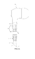
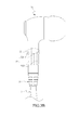
- FIG.2A and FIG.2B show a first embodiment of the earphone for replaceable cables in accordance with the present invention
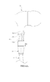
- FIG.3A and FIG.3B show a buckle-up operation of the first embodiment
- FIG.4A and FIG.4B show a pull-off operation of the first embodiment
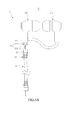
- FIG.5A and FIG.5B show a second embodiment of the earphone for replaceable cables in accordance with the present invention
- the earphone 2 of the invention is to go with a plurality of audio cables 3 with various application lengths.
- Each of the audio cables 3 has an individual audio terminal 31.
- the earphone 2 includes an earphone body 21 and a first buckle structure 22.
- the first buckle structure 22 is formed as an anchoring hole.
- the earphone body 21 further includes a first earphone body 211, a second earphone body 212 and an audio jack 213.
- the first earphone body 211 and the second earphone body 212 are electrically connected.
- the audio jack 213 is constructed to the first earphone body 211.
- the earphone body 21 can be selected from the group of earplug-type earphones, ear-hang-type earphones, head-hookup-type earphones and ear-shielding-type earphones, and the audio jack 213 can be any of the standard 2.5mm, 3.5mm and 6.3mm jacks.
- the anchoring hole 22 is located at the audio jack 213. Upon while the earphone 2 is coupled with any one of the audio cables 3, the audio terminal 3 of the audio cable 3 is plugged in the audio jack 213 of the first earphone body 21.
- the audio cable 3 can include a second buckle structure.
- the second buckle structure is formed as a latch 32 built at the audio terminal 31 to match with the anchoring hole 22 of the first earphone body 21.
- the latch 32 as shown includes a stop protrusion 321 and a spring element 322.
- the stop protrusion 321 is to plug the anchoring hole 22 while the audio terminal 31 mates the audio jack 213.
- One end of the spring element 322 is connected to the stop protrusion 321, while another end thereof is contacted to the audio terminal 31.
- FIG.3A and FIG.3B a typical buckle-up operation of the first embodiment of the earphone is shown.
- the user of the earphone 2 can choose one of the audio cables 3 with an appropriate application length to match the first earphone body 211.
- the audio terminal 31 is sent along a first movement direction D1 to plug the audio jack 213.
- the stop protrusion 321 is compressed by the interior wall of the audio jack 213 to further depress the spring element 322 inward so as to firmly hold the stop protrusion 321 inside the audio jack 213.
- the stop protrusion 321 can buckle up with the anchoring terminal 31 can firmly engage together.
- FIG.4A and FIG.4B a typical pull-off operation of the first embodiment of the earphone is shown. While in a pull-off operation, the stop protrusion 321 is firstly depressed to deflect the spring element 322 inward so as to have the stop protrusion 321 leave the anchoring hole 22, and then the audio terminal 31 can be pulled off the audio jack 213 along a second movement direction D2.
- the user of the earphone can arbitrarily choose a proper audio cable 3 with an appropriate application length.
- the audio terminal 31 of the audio cable 3 can be firmly held by the audio jack 213 of the first earphone body 21.
- the appropriate application length can be provided to the audio cable 3 to meet various application situations, any abrupt movement that shocks the combination of the audio cable 3 and the earphone body 2 cannot separate the earphone assembly of the present invention.
- the application of the earphone can become versatile with the help of plenty extension audio cables 3 with various application lengths.
- FIG.5A and FIG.5B a second embodiment of the earphone for replaceable cables in accordance with the present invention is shown.
- the earphone 2' of the invention is also to go with a plurality of audio cables 3' with various application lengths.
- Each of the audio cables 3' has an individual audio terminal 31'.
- the earphone 2' includes an earphone body 21' and a first buckle structure 22'.
- the first buckle structure 22' is formed as a latch 22'.
- the earphone body 21' further includes a first earphone body 211', a second earphone body 212' and an audio jack 213'.
- the first earphone body 211' and the second earphone body 212' are electrically connected.
- the audio jack 213' is constructed to the first earphone body 211'.
- the earphone body 21' can be selected from the group of earplug-type earphones, ear-hang-type earphones, head-hookup-type earphones and ear-shielding-type earphones, and the audio jack 213' can be any of the standard 2.5mm, 3.5mm and 6.3mm jacks.
- the audio terminal 3' of the audio cable 3' is plugged in the audio jack 213' of the first earphone body 21'.
- the audio cable 3' can include a second buckle structure.
- the second buckle structure is formed as an anchoring hole 32' built at the audio terminal 31' to match with the latch 22' of the first earphone body 21'.
- the latch 22' as shown includes a stop protrusion 221' and a spring element 222'.
- the stop protrusion 221' is to plug the anchoring hole 32' while the audio terminal 31' mates the audio jack 213'.
- One end of the spring element 222' is connected to the stop protrusion 221', while another end thereof is contacted to the audio jack 213'.
- the earphone can then be applicable conveniently to various application environments of any type of the audio source devices without the aforesaid problems described in the background section.
Landscapes
- Physics & Mathematics (AREA)
- Engineering & Computer Science (AREA)
- Acoustics & Sound (AREA)
- Signal Processing (AREA)
- Headphones And Earphones (AREA)
Abstract
Description
- This invention relates to an earphone, more particularly to an earphone that provides connection-ability to various cables.
- In the art, an earphone usually has a fixed extension cable. Referred to
FIG 1 , a typical conventional earphone is shown. The earphone 1 includes a left earplug 11, aright earplug 12 and anaudio cable 13. Theaudio cable 13 further includes anaudio terminal 131. The left earplug 11 is electrically connected with theright earplug 12, and theaudio cable 13 is particularly electrically connected to theleft earplug 12. Theaudio terminal 131 is to couple with an audio jack (not shown in the figure) of an audio source device so as to capture audio media provided by the audio source device. Through theaudio cable 13, the audio media can be then transmitted to the left earplug 11 and theright earplug 12 for broadcasting therefrom. - It is noted that, in a conventional earphone design as disclosed in IG.1, the earphone 1 has a fixed
inseparable audio cable 13, which is connected electrically to one of theearplugs 11 and 12. For the length of theaudio cable 13 is fixed, the applicable length of the earphone 1 to the audio source device is limited to theparticular audio cable 13. Such a fixed-length application of the earphone 1 may cause some inconvenience. For an instance, for alengthy audio cable 13 to be used in a short-length application environment, theaudio cable 13 is usually forced to be wrapped, bent or rolled to fit the limited space. However, such a physical means to shorten the usage length of theaudio cable 13 is sometimes led to a short service life of theaudio cable 13. On the other hand, in the case that ashort audio cable 13 is used to a lengthy application environment, an additional extension cable is usually needed to be connected to theaudio terminal 131 of theaudio cable 13. Otherwise, theaudio terminal 131 is opt to be pull off the audio jack of the audio source device due to unexpected pull forcing from the short-length cable. It is easy to see that the extension cable is definite a cost and may cause some carrying inconvenience. - Therefore, the need to provide an earphone structure that can resolve the aforesaid inconvenience in conventional earphone usage is definitely obvious
- Accordingly, it is a primary object of the present invention to provide an earphone for replaceable cables. The earphone of the present invention applicable to adapt cables with various lengths comprises an earphone body further having an audio jack to electrically couple with one of the cables.
- It is another object of the present invention to provide an earphone that can ensure the separable connection between the earphone body and the cable by providing a first buckle structure to the earphone body.
- In the present invention, the earphone includes an earphone body that can receive, in a separable manner, one of plural audio cables with different lengths. Each of the audio cables has an individual audio terminal. The earphone further includes a first buckle structure to ensure the separable connection between the audio jack of the earphone body and the audio terminal of a respective audio cable. Preferably, the first buckle structure can be located at the audio jack.
- By providing the separable connection between the earphone body of the earphone and one of the audio cables with various application lengths in accordance with the present invention, the earphone can then be applicable conveniently to various application environments of the audio source device without the aforesaid problems described in the background section.
- All these objects are achieved by the earphone for replaceable cables described below.
- The present invention will now be specified with reference to its preferred embodiment illustrated in the drawings, in which:
-
FIG.1 shows a typical convention earphone; -
FIG.2A andFIG.2B show a first embodiment of the earphone for replaceable cables in accordance with the present invention; -
FIG.3A andFIG.3B show a buckle-up operation of the first embodiment; -
FIG.4A andFIG.4B show a pull-off operation of the first embodiment; and -
FIG.5A andFIG.5B show a second embodiment of the earphone for replaceable cables in accordance with the present invention - The invention disclosed herein is directed to an earphone for replaceable cables. In the following description, numerous details are set forth in order to provide a thorough understanding of the present invention. It will be appreciated by one skilled in the art that variations of these specific details are possible while still achieving the results of the present invention. In other instance, well-known components are not described in detail in order not to unnecessarily obscure the present invention.
- Referring now to
FIG.2A andFIG.2B , a first embodiment of the earphone for replaceable cables in accordance with the present invention is shown. Theearphone 2 of the invention is to go with a plurality ofaudio cables 3 with various application lengths. Each of theaudio cables 3 has anindividual audio terminal 31. Theearphone 2 includes anearphone body 21 and afirst buckle structure 22. In this embodiment as shown inFIG.2A andFIG.2B , thefirst buckle structure 22 is formed as an anchoring hole. - The
earphone body 21 further includes afirst earphone body 211, asecond earphone body 212 and anaudio jack 213. Thefirst earphone body 211 and thesecond earphone body 212 are electrically connected. Theaudio jack 213 is constructed to thefirst earphone body 211. - In the present invention, the
earphone body 21 can be selected from the group of earplug-type earphones, ear-hang-type earphones, head-hookup-type earphones and ear-shielding-type earphones, and theaudio jack 213 can be any of the standard 2.5mm, 3.5mm and 6.3mm jacks. - The
anchoring hole 22 is located at theaudio jack 213. Upon while theearphone 2 is coupled with any one of theaudio cables 3, theaudio terminal 3 of theaudio cable 3 is plugged in theaudio jack 213 of thefirst earphone body 21. - Further, the
audio cable 3 can include a second buckle structure. As shown in this first embodiment, the second buckle structure is formed as alatch 32 built at theaudio terminal 31 to match with theanchoring hole 22 of thefirst earphone body 21. - The
latch 32 as shown includes astop protrusion 321 and aspring element 322. Thestop protrusion 321 is to plug theanchoring hole 22 while theaudio terminal 31 mates theaudio jack 213. One end of thespring element 322 is connected to thestop protrusion 321, while another end thereof is contacted to theaudio terminal 31. - Referring now to
FIG.3A andFIG.3B , a typical buckle-up operation of the first embodiment of the earphone is shown. In the present invention, the user of theearphone 2 can choose one of theaudio cables 3 with an appropriate application length to match thefirst earphone body 211. In connection, theaudio terminal 31 is sent along a first movement direction D1 to plug theaudio jack 213. Meanwhile, thestop protrusion 321 is compressed by the interior wall of theaudio jack 213 to further depress thespring element 322 inward so as to firmly hold thestop protrusion 321 inside theaudio jack 213. - By providing the elastic forcing of the
spring element 322 while theaudio terminal 31 mates theaudio jack 213 along the direction D11 in accordance with the present invention, thestop protrusion 321 can buckle up with theanchoring terminal 31 can firmly engage together. - Referring now to
FIG.4A andFIG.4B , a typical pull-off operation of the first embodiment of the earphone is shown. While in a pull-off operation, thestop protrusion 321 is firstly depressed to deflect thespring element 322 inward so as to have thestop protrusion 321 leave theanchoring hole 22, and then theaudio terminal 31 can be pulled off theaudio jack 213 along a second movement direction D2. - While the
audio terminal 31 totally leaves the audio jack 23, thespring element 322 can resume to its original free state. - By providing the present invention, the user of the earphone can arbitrarily choose a
proper audio cable 3 with an appropriate application length. With the help of the buckle-up operation between the stop protrusion 32 (i.e. the latch) and the anchoringhole 22, theaudio terminal 31 of theaudio cable 3 can be firmly held by theaudio jack 213 of thefirst earphone body 21. Upon such an arrangement, since the appropriate application length can be provided to theaudio cable 3 to meet various application situations, any abrupt movement that shocks the combination of theaudio cable 3 and theearphone body 2 cannot separate the earphone assembly of the present invention. - Further, in the case of applying a huge-occupation audio device which is hard to be moved in any time, the application of the earphone can become versatile with the help of plenty
extension audio cables 3 with various application lengths. - Referring now to
FIG.5A andFIG.5B , a second embodiment of the earphone for replaceable cables in accordance with the present invention is shown. The earphone 2' of the invention is also to go with a plurality of audio cables 3' with various application lengths. Each of the audio cables 3' has an individual audio terminal 31'. The earphone 2' includes an earphone body 21' and a first buckle structure 22'. In this embodiment as shown inFIG.5A andFIG.5B , the first buckle structure 22' is formed as a latch 22'. - The earphone body 21' further includes a first earphone body 211', a second earphone body 212' and an audio jack 213'. The first earphone body 211' and the second earphone body 212' are electrically connected. The audio jack 213' is constructed to the first earphone body 211'. The earphone body 21' can be selected from the group of earplug-type earphones, ear-hang-type earphones, head-hookup-type earphones and ear-shielding-type earphones, and the audio jack 213' can be any of the standard 2.5mm, 3.5mm and 6.3mm jacks.
- Upon while the earphone 2' is coupled with any one of the audio cables 3', the audio terminal 3' of the audio cable 3' is plugged in the audio jack 213' of the first earphone body 21'.
- Further, the audio cable 3' can include a second buckle structure. As shown in this second embodiment, the second buckle structure is formed as an anchoring hole 32' built at the audio terminal 31' to match with the latch 22' of the first earphone body 21'.
- The latch 22' as shown includes a stop protrusion 221' and a spring element 222'. The stop protrusion 221' is to plug the anchoring hole 32' while the audio terminal 31' mates the audio jack 213'. One end of the spring element 222' is connected to the stop protrusion 221', while another end thereof is contacted to the audio jack 213'.
- Beside the aforesaid structural differences between the first embodiment and the second embodiment in accordance with the present invention, the foregoing buckle-up and pull-off operations of the first embodiment are also applied to the second embodiment. Therefore, details thereabout are omitted herein.
- By providing the separable connection and the firm-engagement buckle mechanism between the
earphone body 2, 2' of the earphone and one of theaudio cables 3, 3' with various application lengths in accordance with the present invention, the earphone can then be applicable conveniently to various application environments of any type of the audio source devices without the aforesaid problems described in the background section. - While the present invention has been particularly shown and described with reference to a preferred embodiment, it will be understood by those skilled in the art that various changes in form and detail may be without departing from the spirit and scope of the present invention.
Claims (9)
- An earphone to fit with a plurality of audio cables having individual audio terminals, comprising:an earphone body;characterized in that an earphone body further including an audio jack to couple with one of the audio terminals and a first buckle structure comprising located at the audio jack for providing a firm connection between said one of the audio terminals and the audio jack.
- The earphone according to claim 1, wherein said earphone body further includes a first earphone body and said audio jack is located at the first earphone body.
- The earphone according to claim 2, wherein said earphone body further includes a second earphone body electrically connected with said first earphone body.
- The earphone according to claim 1, wherein said earphone body is selected from the group of earplug-type earphones, ear-hang-type earphones, head-hookup-type earphones and ear-shielding-type earphones.
- The earphone according to claim 1, wherein said first buckle structure includes at least a latch.
- The earphone according to claim 5, wherein said latch further includes:a stop protrusion to be received by an anchoring hole of said audio jack upon while said audio terminal is coupled with said audio jack; anda spring element mounted to the stop protrusion.
- The earphone according to claim 6, wherein said audio terminal further includes a second buckle structure having said anchoring hole.
- The earphone according to claim 1, wherein said first buckle structure includes at least an anchoring hole, said audio terminal further includes a second buckle structure having at least a latch to pair with the anchoring hole.
- The earphone according to claim 8, wherein said latch further includes:a stop protrusion to be received by said anchoring hole upon while said audio terminal is coupled with said audio jack; anda spring element mounted to the stop protrusion.
Priority Applications (1)
| Application Number | Priority Date | Filing Date | Title |
|---|---|---|---|
| EP10161284.4A EP2384020B1 (en) | 2010-04-28 | 2010-04-28 | Earphone with replaceable cable |
Applications Claiming Priority (1)
| Application Number | Priority Date | Filing Date | Title |
|---|---|---|---|
| EP10161284.4A EP2384020B1 (en) | 2010-04-28 | 2010-04-28 | Earphone with replaceable cable |
Publications (2)
| Publication Number | Publication Date |
|---|---|
| EP2384020A1 true EP2384020A1 (en) | 2011-11-02 |
| EP2384020B1 EP2384020B1 (en) | 2017-10-11 |
Family
ID=42732477
Family Applications (1)
| Application Number | Title | Priority Date | Filing Date |
|---|---|---|---|
| EP10161284.4A Not-in-force EP2384020B1 (en) | 2010-04-28 | 2010-04-28 | Earphone with replaceable cable |
Country Status (1)
| Country | Link |
|---|---|
| EP (1) | EP2384020B1 (en) |
Cited By (5)
| Publication number | Priority date | Publication date | Assignee | Title |
|---|---|---|---|---|
| CN104780478A (en) * | 2015-03-27 | 2015-07-15 | 许永胜 | Earphone plug |
| WO2016000611A1 (en) * | 2014-07-04 | 2016-01-07 | 王玮冰 | Audio transmission circuit |
| TWI549520B (en) * | 2013-10-10 | 2016-09-11 | Molex Inc | Receiver |
| CN108495228A (en) * | 2018-06-21 | 2018-09-04 | 广东朝阳电子科技股份有限公司 | Enhance the earphone wire structure and preparation method thereof of cableties pulling force |
| DE102017121137A1 (en) * | 2017-09-13 | 2019-03-14 | Sennheiser Electronic Gmbh & Co. Kg | Earphones with removable connection cable |
Citations (4)
| Publication number | Priority date | Publication date | Assignee | Title |
|---|---|---|---|---|
| FR1110464A (en) * | 1954-09-03 | 1956-02-13 | D Acoustique Soc Ind | Lock for detachable cord earphones and other applications |
| US4499593A (en) * | 1983-07-25 | 1985-02-12 | Antle Gary W | Modular stereo headphones |
| WO2003015463A2 (en) * | 2001-08-10 | 2003-02-20 | Hear-Wear Technologies, Llc | A bte/cic auditory device and modular connector system therefor |
| US20060133632A1 (en) * | 2004-12-22 | 2006-06-22 | Ultimate Ears, Llc | In-ear monitors with removable cables |
-
2010
- 2010-04-28 EP EP10161284.4A patent/EP2384020B1/en not_active Not-in-force
Patent Citations (4)
| Publication number | Priority date | Publication date | Assignee | Title |
|---|---|---|---|---|
| FR1110464A (en) * | 1954-09-03 | 1956-02-13 | D Acoustique Soc Ind | Lock for detachable cord earphones and other applications |
| US4499593A (en) * | 1983-07-25 | 1985-02-12 | Antle Gary W | Modular stereo headphones |
| WO2003015463A2 (en) * | 2001-08-10 | 2003-02-20 | Hear-Wear Technologies, Llc | A bte/cic auditory device and modular connector system therefor |
| US20060133632A1 (en) * | 2004-12-22 | 2006-06-22 | Ultimate Ears, Llc | In-ear monitors with removable cables |
Cited By (10)
| Publication number | Priority date | Publication date | Assignee | Title |
|---|---|---|---|---|
| TWI549520B (en) * | 2013-10-10 | 2016-09-11 | Molex Inc | Receiver |
| WO2016000611A1 (en) * | 2014-07-04 | 2016-01-07 | 王玮冰 | Audio transmission circuit |
| CN105323676A (en) * | 2014-07-04 | 2016-02-10 | 杭州纳雄科技有限公司 | Audio transmission circuit |
| CN105323676B (en) * | 2014-07-04 | 2019-05-03 | 杭州纳雄科技有限公司 | Audio transmission circuit |
| CN104780478A (en) * | 2015-03-27 | 2015-07-15 | 许永胜 | Earphone plug |
| DE102017121137A1 (en) * | 2017-09-13 | 2019-03-14 | Sennheiser Electronic Gmbh & Co. Kg | Earphones with removable connection cable |
| US10924840B2 (en) | 2017-09-13 | 2021-02-16 | Sennheiser Electronic Gmbh & Co. Kg | Earphones with removable connection cable |
| DE102017121137B4 (en) | 2017-09-13 | 2022-11-17 | Sennheiser Electronic Gmbh & Co. Kg | Earphones with detachable connection cable |
| CN108495228A (en) * | 2018-06-21 | 2018-09-04 | 广东朝阳电子科技股份有限公司 | Enhance the earphone wire structure and preparation method thereof of cableties pulling force |
| CN108495228B (en) * | 2018-06-21 | 2024-05-07 | 广东朝阳电子科技股份有限公司 | Earphone wire structure for enhancing wire buckle tension and manufacturing method thereof |
Also Published As
| Publication number | Publication date |
|---|---|
| EP2384020B1 (en) | 2017-10-11 |
Similar Documents
| Publication | Publication Date | Title |
|---|---|---|
| EP2384020B1 (en) | Earphone with replaceable cable | |
| US20110299714A1 (en) | Earphone for replaceable cables | |
| US6337444B1 (en) | Wire winding box with replaceable connecting receptacle | |
| US9190760B2 (en) | Plug structure for connecting sockets | |
| DE50311140D1 (en) | Spring terminal connection for an electrical conductor | |
| US7357666B2 (en) | Cable winder | |
| CN105465657A (en) | LED lamp and its lamp holder structure | |
| US8398428B2 (en) | Reel for minimizing unreeled cable length | |
| US20140302695A1 (en) | Connector | |
| US20140220828A1 (en) | Signal connector module | |
| DE60313511D1 (en) | coaxial | |
| EP2953209B1 (en) | Terminal attachment base, terminal, and audio apparatus | |
| EP1096760A1 (en) | A wire winding box with a replaceable connecting receptacle | |
| US8371870B2 (en) | Mouse device with a separable transmission cable | |
| US9570860B1 (en) | Electrical connector providing secured plugging and convenient unplugging | |
| JP3189714U (en) | plug | |
| KR101705021B1 (en) | Automatic winding device having side push key | |
| CN105186194A (en) | Data line flexible fastening structure | |
| JP2015173136A (en) | connector | |
| JP6447635B2 (en) | Cassette and inspection unit | |
| CN101841752A (en) | earphone | |
| KR200486517Y1 (en) | Earth terminal connection syrcture of consent for electric wire reel | |
| KR101674072B1 (en) | Automatic winding device having pin terminal | |
| KR101121011B1 (en) | Divisible sound output device | |
| KR102915854B1 (en) | Safety electric plug for fully binding recognition |
Legal Events
| Date | Code | Title | Description |
|---|---|---|---|
| 17P | Request for examination filed |
Effective date: 20101225 |
|
| AK | Designated contracting states |
Kind code of ref document: A1 Designated state(s): AT BE BG CH CY CZ DE DK EE ES FI FR GB GR HR HU IE IS IT LI LT LU LV MC MK MT NL NO PL PT RO SE SI SK SM TR |
|
| AX | Request for extension of the european patent |
Extension state: AL BA ME RS |
|
| PUAI | Public reference made under article 153(3) epc to a published international application that has entered the european phase |
Free format text: ORIGINAL CODE: 0009012 |
|
| RAP1 | Party data changed (applicant data changed or rights of an application transferred) |
Owner name: GIGA-BYTE TECHNOLOGY CO., LTD. |
|
| 17Q | First examination report despatched |
Effective date: 20160519 |
|
| STAA | Information on the status of an ep patent application or granted ep patent |
Free format text: STATUS: EXAMINATION IS IN PROGRESS |
|
| GRAP | Despatch of communication of intention to grant a patent |
Free format text: ORIGINAL CODE: EPIDOSNIGR1 |
|
| STAA | Information on the status of an ep patent application or granted ep patent |
Free format text: STATUS: GRANT OF PATENT IS INTENDED |
|
| INTG | Intention to grant announced |
Effective date: 20170707 |
|
| GRAS | Grant fee paid |
Free format text: ORIGINAL CODE: EPIDOSNIGR3 |
|
| GRAA | (expected) grant |
Free format text: ORIGINAL CODE: 0009210 |
|
| STAA | Information on the status of an ep patent application or granted ep patent |
Free format text: STATUS: THE PATENT HAS BEEN GRANTED |
|
| AK | Designated contracting states |
Kind code of ref document: B1 Designated state(s): AT BE BG CH CY CZ DE DK EE ES FI FR GB GR HR HU IE IS IT LI LT LU LV MC MK MT NL NO PL PT RO SE SI SK SM TR |
|
| REG | Reference to a national code |
Ref country code: GB Ref legal event code: FG4D |
|
| REG | Reference to a national code |
Ref country code: CH Ref legal event code: EP |
|
| REG | Reference to a national code |
Ref country code: IE Ref legal event code: FG4D |
|
| REG | Reference to a national code |
Ref country code: AT Ref legal event code: REF Ref document number: 936994 Country of ref document: AT Kind code of ref document: T Effective date: 20171115 |
|
| REG | Reference to a national code |
Ref country code: DE Ref legal event code: R096 Ref document number: 602010045854 Country of ref document: DE |
|
| REG | Reference to a national code |
Ref country code: NL Ref legal event code: MP Effective date: 20171011 |
|
| REG | Reference to a national code |
Ref country code: LT Ref legal event code: MG4D |
|
| REG | Reference to a national code |
Ref country code: AT Ref legal event code: MK05 Ref document number: 936994 Country of ref document: AT Kind code of ref document: T Effective date: 20171011 Ref country code: FR Ref legal event code: PLFP Year of fee payment: 9 |
|
| PG25 | Lapsed in a contracting state [announced via postgrant information from national office to epo] |
Ref country code: NL Free format text: LAPSE BECAUSE OF FAILURE TO SUBMIT A TRANSLATION OF THE DESCRIPTION OR TO PAY THE FEE WITHIN THE PRESCRIBED TIME-LIMIT Effective date: 20171011 |
|
| PG25 | Lapsed in a contracting state [announced via postgrant information from national office to epo] |
Ref country code: ES Free format text: LAPSE BECAUSE OF FAILURE TO SUBMIT A TRANSLATION OF THE DESCRIPTION OR TO PAY THE FEE WITHIN THE PRESCRIBED TIME-LIMIT Effective date: 20171011 Ref country code: LT Free format text: LAPSE BECAUSE OF FAILURE TO SUBMIT A TRANSLATION OF THE DESCRIPTION OR TO PAY THE FEE WITHIN THE PRESCRIBED TIME-LIMIT Effective date: 20171011 Ref country code: SE Free format text: LAPSE BECAUSE OF FAILURE TO SUBMIT A TRANSLATION OF THE DESCRIPTION OR TO PAY THE FEE WITHIN THE PRESCRIBED TIME-LIMIT Effective date: 20171011 Ref country code: FI Free format text: LAPSE BECAUSE OF FAILURE TO SUBMIT A TRANSLATION OF THE DESCRIPTION OR TO PAY THE FEE WITHIN THE PRESCRIBED TIME-LIMIT Effective date: 20171011 Ref country code: NO Free format text: LAPSE BECAUSE OF FAILURE TO SUBMIT A TRANSLATION OF THE DESCRIPTION OR TO PAY THE FEE WITHIN THE PRESCRIBED TIME-LIMIT Effective date: 20180111 |
|
| PGFP | Annual fee paid to national office [announced via postgrant information from national office to epo] |
Ref country code: GB Payment date: 20180329 Year of fee payment: 9 |
|
| PG25 | Lapsed in a contracting state [announced via postgrant information from national office to epo] |
Ref country code: AT Free format text: LAPSE BECAUSE OF FAILURE TO SUBMIT A TRANSLATION OF THE DESCRIPTION OR TO PAY THE FEE WITHIN THE PRESCRIBED TIME-LIMIT Effective date: 20171011 Ref country code: HR Free format text: LAPSE BECAUSE OF FAILURE TO SUBMIT A TRANSLATION OF THE DESCRIPTION OR TO PAY THE FEE WITHIN THE PRESCRIBED TIME-LIMIT Effective date: 20171011 Ref country code: GR Free format text: LAPSE BECAUSE OF FAILURE TO SUBMIT A TRANSLATION OF THE DESCRIPTION OR TO PAY THE FEE WITHIN THE PRESCRIBED TIME-LIMIT Effective date: 20180112 Ref country code: BG Free format text: LAPSE BECAUSE OF FAILURE TO SUBMIT A TRANSLATION OF THE DESCRIPTION OR TO PAY THE FEE WITHIN THE PRESCRIBED TIME-LIMIT Effective date: 20180111 Ref country code: IS Free format text: LAPSE BECAUSE OF FAILURE TO SUBMIT A TRANSLATION OF THE DESCRIPTION OR TO PAY THE FEE WITHIN THE PRESCRIBED TIME-LIMIT Effective date: 20180211 Ref country code: LV Free format text: LAPSE BECAUSE OF FAILURE TO SUBMIT A TRANSLATION OF THE DESCRIPTION OR TO PAY THE FEE WITHIN THE PRESCRIBED TIME-LIMIT Effective date: 20171011 |
|
| PGFP | Annual fee paid to national office [announced via postgrant information from national office to epo] |
Ref country code: FR Payment date: 20180315 Year of fee payment: 9 |
|
| REG | Reference to a national code |
Ref country code: DE Ref legal event code: R097 Ref document number: 602010045854 Country of ref document: DE |
|
| PG25 | Lapsed in a contracting state [announced via postgrant information from national office to epo] |
Ref country code: CZ Free format text: LAPSE BECAUSE OF FAILURE TO SUBMIT A TRANSLATION OF THE DESCRIPTION OR TO PAY THE FEE WITHIN THE PRESCRIBED TIME-LIMIT Effective date: 20171011 Ref country code: SK Free format text: LAPSE BECAUSE OF FAILURE TO SUBMIT A TRANSLATION OF THE DESCRIPTION OR TO PAY THE FEE WITHIN THE PRESCRIBED TIME-LIMIT Effective date: 20171011 Ref country code: EE Free format text: LAPSE BECAUSE OF FAILURE TO SUBMIT A TRANSLATION OF THE DESCRIPTION OR TO PAY THE FEE WITHIN THE PRESCRIBED TIME-LIMIT Effective date: 20171011 Ref country code: DK Free format text: LAPSE BECAUSE OF FAILURE TO SUBMIT A TRANSLATION OF THE DESCRIPTION OR TO PAY THE FEE WITHIN THE PRESCRIBED TIME-LIMIT Effective date: 20171011 |
|
| PGFP | Annual fee paid to national office [announced via postgrant information from national office to epo] |
Ref country code: DE Payment date: 20180417 Year of fee payment: 9 |
|
| PLBE | No opposition filed within time limit |
Free format text: ORIGINAL CODE: 0009261 |
|
| STAA | Information on the status of an ep patent application or granted ep patent |
Free format text: STATUS: NO OPPOSITION FILED WITHIN TIME LIMIT |
|
| PG25 | Lapsed in a contracting state [announced via postgrant information from national office to epo] |
Ref country code: RO Free format text: LAPSE BECAUSE OF FAILURE TO SUBMIT A TRANSLATION OF THE DESCRIPTION OR TO PAY THE FEE WITHIN THE PRESCRIBED TIME-LIMIT Effective date: 20171011 Ref country code: PL Free format text: LAPSE BECAUSE OF FAILURE TO SUBMIT A TRANSLATION OF THE DESCRIPTION OR TO PAY THE FEE WITHIN THE PRESCRIBED TIME-LIMIT Effective date: 20171011 Ref country code: SM Free format text: LAPSE BECAUSE OF FAILURE TO SUBMIT A TRANSLATION OF THE DESCRIPTION OR TO PAY THE FEE WITHIN THE PRESCRIBED TIME-LIMIT Effective date: 20171011 Ref country code: IT Free format text: LAPSE BECAUSE OF FAILURE TO SUBMIT A TRANSLATION OF THE DESCRIPTION OR TO PAY THE FEE WITHIN THE PRESCRIBED TIME-LIMIT Effective date: 20171011 |
|
| 26N | No opposition filed |
Effective date: 20180712 |
|
| PG25 | Lapsed in a contracting state [announced via postgrant information from national office to epo] |
Ref country code: MC Free format text: LAPSE BECAUSE OF FAILURE TO SUBMIT A TRANSLATION OF THE DESCRIPTION OR TO PAY THE FEE WITHIN THE PRESCRIBED TIME-LIMIT Effective date: 20171011 Ref country code: SI Free format text: LAPSE BECAUSE OF FAILURE TO SUBMIT A TRANSLATION OF THE DESCRIPTION OR TO PAY THE FEE WITHIN THE PRESCRIBED TIME-LIMIT Effective date: 20171011 |
|
| REG | Reference to a national code |
Ref country code: CH Ref legal event code: PL |
|
| REG | Reference to a national code |
Ref country code: BE Ref legal event code: MM Effective date: 20180430 |
|
| REG | Reference to a national code |
Ref country code: IE Ref legal event code: MM4A |
|
| PG25 | Lapsed in a contracting state [announced via postgrant information from national office to epo] |
Ref country code: LU Free format text: LAPSE BECAUSE OF NON-PAYMENT OF DUE FEES Effective date: 20180428 |
|
| PG25 | Lapsed in a contracting state [announced via postgrant information from national office to epo] |
Ref country code: LI Free format text: LAPSE BECAUSE OF NON-PAYMENT OF DUE FEES Effective date: 20180430 Ref country code: BE Free format text: LAPSE BECAUSE OF NON-PAYMENT OF DUE FEES Effective date: 20180430 Ref country code: CH Free format text: LAPSE BECAUSE OF NON-PAYMENT OF DUE FEES Effective date: 20180430 |
|
| PG25 | Lapsed in a contracting state [announced via postgrant information from national office to epo] |
Ref country code: IE Free format text: LAPSE BECAUSE OF NON-PAYMENT OF DUE FEES Effective date: 20180428 |
|
| REG | Reference to a national code |
Ref country code: DE Ref legal event code: R119 Ref document number: 602010045854 Country of ref document: DE |
|
| GBPC | Gb: european patent ceased through non-payment of renewal fee |
Effective date: 20190428 |
|
| PG25 | Lapsed in a contracting state [announced via postgrant information from national office to epo] |
Ref country code: GB Free format text: LAPSE BECAUSE OF NON-PAYMENT OF DUE FEES Effective date: 20190428 Ref country code: MT Free format text: LAPSE BECAUSE OF NON-PAYMENT OF DUE FEES Effective date: 20180428 Ref country code: DE Free format text: LAPSE BECAUSE OF NON-PAYMENT OF DUE FEES Effective date: 20191101 |
|
| PG25 | Lapsed in a contracting state [announced via postgrant information from national office to epo] |
Ref country code: FR Free format text: LAPSE BECAUSE OF NON-PAYMENT OF DUE FEES Effective date: 20190430 |
|
| PG25 | Lapsed in a contracting state [announced via postgrant information from national office to epo] |
Ref country code: TR Free format text: LAPSE BECAUSE OF FAILURE TO SUBMIT A TRANSLATION OF THE DESCRIPTION OR TO PAY THE FEE WITHIN THE PRESCRIBED TIME-LIMIT Effective date: 20171011 |
|
| PG25 | Lapsed in a contracting state [announced via postgrant information from national office to epo] |
Ref country code: PT Free format text: LAPSE BECAUSE OF FAILURE TO SUBMIT A TRANSLATION OF THE DESCRIPTION OR TO PAY THE FEE WITHIN THE PRESCRIBED TIME-LIMIT Effective date: 20171011 Ref country code: HU Free format text: LAPSE BECAUSE OF FAILURE TO SUBMIT A TRANSLATION OF THE DESCRIPTION OR TO PAY THE FEE WITHIN THE PRESCRIBED TIME-LIMIT; INVALID AB INITIO Effective date: 20100428 |
|
| PG25 | Lapsed in a contracting state [announced via postgrant information from national office to epo] |
Ref country code: CY Free format text: LAPSE BECAUSE OF FAILURE TO SUBMIT A TRANSLATION OF THE DESCRIPTION OR TO PAY THE FEE WITHIN THE PRESCRIBED TIME-LIMIT Effective date: 20171011 Ref country code: MK Free format text: LAPSE BECAUSE OF NON-PAYMENT OF DUE FEES Effective date: 20171011 |