EP2384002B1 - Moving picture decoding method using additional quantization matrices - Google Patents
Moving picture decoding method using additional quantization matrices Download PDFInfo
- Publication number
- EP2384002B1 EP2384002B1 EP11175220.0A EP11175220A EP2384002B1 EP 2384002 B1 EP2384002 B1 EP 2384002B1 EP 11175220 A EP11175220 A EP 11175220A EP 2384002 B1 EP2384002 B1 EP 2384002B1
- Authority
- EP
- European Patent Office
- Prior art keywords
- quantization matrix
- matrix
- picture
- quantization
- coding
- Prior art date
- Legal status (The legal status is an assumption and is not a legal conclusion. Google has not performed a legal analysis and makes no representation as to the accuracy of the status listed.)
- Active
Links
- 238000013139 quantization Methods 0.000 title claims description 166
- 238000000034 method Methods 0.000 title claims description 35
- 239000011159 matrix material Substances 0.000 claims description 151
- 241000023320 Luma <angiosperm> Species 0.000 claims description 11
- OSWPMRLSEDHDFF-UHFFFAOYSA-N methyl salicylate Chemical compound COC(=O)C1=CC=CC=C1O OSWPMRLSEDHDFF-UHFFFAOYSA-N 0.000 claims description 11
- 238000010586 diagram Methods 0.000 description 24
- 239000013598 vector Substances 0.000 description 13
- 230000009466 transformation Effects 0.000 description 10
- 230000006835 compression Effects 0.000 description 8
- 238000007906 compression Methods 0.000 description 8
- 230000005540 biological transmission Effects 0.000 description 4
- 230000001413 cellular effect Effects 0.000 description 3
- 230000002123 temporal effect Effects 0.000 description 2
- 102100037812 Medium-wave-sensitive opsin 1 Human genes 0.000 description 1
- 239000000284 extract Substances 0.000 description 1
- 230000008520 organization Effects 0.000 description 1
- 230000000750 progressive effect Effects 0.000 description 1
Images


Classifications
-
- H—ELECTRICITY
- H04—ELECTRIC COMMUNICATION TECHNIQUE
- H04N—PICTORIAL COMMUNICATION, e.g. TELEVISION
- H04N7/00—Television systems
- H04N7/24—Systems for the transmission of television signals using pulse code modulation
-
- H—ELECTRICITY
- H04—ELECTRIC COMMUNICATION TECHNIQUE
- H04N—PICTORIAL COMMUNICATION, e.g. TELEVISION
- H04N19/00—Methods or arrangements for coding, decoding, compressing or decompressing digital video signals
- H04N19/10—Methods or arrangements for coding, decoding, compressing or decompressing digital video signals using adaptive coding
- H04N19/169—Methods or arrangements for coding, decoding, compressing or decompressing digital video signals using adaptive coding characterised by the coding unit, i.e. the structural portion or semantic portion of the video signal being the object or the subject of the adaptive coding
- H04N19/188—Methods or arrangements for coding, decoding, compressing or decompressing digital video signals using adaptive coding characterised by the coding unit, i.e. the structural portion or semantic portion of the video signal being the object or the subject of the adaptive coding the unit being a video data packet, e.g. a network abstraction layer [NAL] unit
-
- H—ELECTRICITY
- H04—ELECTRIC COMMUNICATION TECHNIQUE
- H04N—PICTORIAL COMMUNICATION, e.g. TELEVISION
- H04N19/00—Methods or arrangements for coding, decoding, compressing or decompressing digital video signals
- H04N19/10—Methods or arrangements for coding, decoding, compressing or decompressing digital video signals using adaptive coding
- H04N19/102—Methods or arrangements for coding, decoding, compressing or decompressing digital video signals using adaptive coding characterised by the element, parameter or selection affected or controlled by the adaptive coding
- H04N19/124—Quantisation
- H04N19/126—Details of normalisation or weighting functions, e.g. normalisation matrices or variable uniform quantisers
-
- H—ELECTRICITY
- H04—ELECTRIC COMMUNICATION TECHNIQUE
- H04N—PICTORIAL COMMUNICATION, e.g. TELEVISION
- H04N19/00—Methods or arrangements for coding, decoding, compressing or decompressing digital video signals
- H04N19/10—Methods or arrangements for coding, decoding, compressing or decompressing digital video signals using adaptive coding
- H04N19/134—Methods or arrangements for coding, decoding, compressing or decompressing digital video signals using adaptive coding characterised by the element, parameter or criterion affecting or controlling the adaptive coding
- H04N19/157—Assigned coding mode, i.e. the coding mode being predefined or preselected to be further used for selection of another element or parameter
- H04N19/159—Prediction type, e.g. intra-frame, inter-frame or bidirectional frame prediction
-
- H—ELECTRICITY
- H04—ELECTRIC COMMUNICATION TECHNIQUE
- H04N—PICTORIAL COMMUNICATION, e.g. TELEVISION
- H04N19/00—Methods or arrangements for coding, decoding, compressing or decompressing digital video signals
- H04N19/10—Methods or arrangements for coding, decoding, compressing or decompressing digital video signals using adaptive coding
- H04N19/169—Methods or arrangements for coding, decoding, compressing or decompressing digital video signals using adaptive coding characterised by the coding unit, i.e. the structural portion or semantic portion of the video signal being the object or the subject of the adaptive coding
- H04N19/186—Methods or arrangements for coding, decoding, compressing or decompressing digital video signals using adaptive coding characterised by the coding unit, i.e. the structural portion or semantic portion of the video signal being the object or the subject of the adaptive coding the unit being a colour or a chrominance component
-
- H—ELECTRICITY
- H04—ELECTRIC COMMUNICATION TECHNIQUE
- H04N—PICTORIAL COMMUNICATION, e.g. TELEVISION
- H04N19/00—Methods or arrangements for coding, decoding, compressing or decompressing digital video signals
- H04N19/60—Methods or arrangements for coding, decoding, compressing or decompressing digital video signals using transform coding
- H04N19/61—Methods or arrangements for coding, decoding, compressing or decompressing digital video signals using transform coding in combination with predictive coding
-
- H—ELECTRICITY
- H04—ELECTRIC COMMUNICATION TECHNIQUE
- H04N—PICTORIAL COMMUNICATION, e.g. TELEVISION
- H04N19/00—Methods or arrangements for coding, decoding, compressing or decompressing digital video signals
- H04N19/70—Methods or arrangements for coding, decoding, compressing or decompressing digital video signals characterised by syntax aspects related to video coding, e.g. related to compression standards
-
- H—ELECTRICITY
- H04—ELECTRIC COMMUNICATION TECHNIQUE
- H04N—PICTORIAL COMMUNICATION, e.g. TELEVISION
- H04N21/00—Selective content distribution, e.g. interactive television or video on demand [VOD]
- H04N21/20—Servers specifically adapted for the distribution of content, e.g. VOD servers; Operations thereof
- H04N21/23—Processing of content or additional data; Elementary server operations; Server middleware
- H04N21/236—Assembling of a multiplex stream, e.g. transport stream, by combining a video stream with other content or additional data, e.g. inserting a URL [Uniform Resource Locator] into a video stream, multiplexing software data into a video stream; Remultiplexing of multiplex streams; Insertion of stuffing bits into the multiplex stream, e.g. to obtain a constant bit-rate; Assembling of a packetised elementary stream
Definitions
- the present invention relates to a moving picture coding method for coding moving pictures and generating streams and a moving picture decoding method for decoding such coded streams, as well as the streams.
- multimedia which integrally handles audio, video and other pixel values
- existing information media i.e., newspaper, magazine, television, radio, telephone and other means through which information is conveyed to people
- multimedia refers to something that is represented by associating not only characters, but also graphics, audio, and especially pictures and the like together.
- existing information media it appears as a prerequisite to represent such information in digital form.
- the amount of information contained in each of the aforementioned information media is 64Kbits per second in the case of audio (telephone quality), and 100Mbits per second in the case of moving pictures (current television reception quality). Therefore, it is not realistic for the aforementioned information media to handle such an enormous amount of information as it is in digital form.
- ISDN Integrated Services Digital Network
- MPEG Moving Picture Experts Group
- ISO/IEC International Organization for Standardization, International Electrotechnical Commission
- MPEG-1 is a standard for compressing television signal information approximately into one hundredth so that moving picture signals can be transmitted at a rate of 1.5 Mbit/s.
- MPEG-2 which was standardized with a view to satisfying requirements for further improved picture quality, allows data transmission equivalent in quality to television broadcasting through which moving picture signals are transmitted at a rate of 2 to 15Mbit/s.
- MPEG-4 was standardized by the working group (ISO/IEC JTC1/SC29/WG11) which promoted the standardization of MPEG-1 and MPEG-2.
- MPEG-4 which provides a higher compression ratio than that of MPEG-1 and MPEG-2 and which enables an object-based coding/decoding/operation, is capable of providing a new functionality required in this age of multimedia.
- MPEG-4 aimed at providing a low bit rate coding method, but it has been extended as a standard supporting more general coding that handles interlaced images as well as high bit rate coding.
- inter picture prediction coding aiming at reducing temporal redundancies, motion estimation and generation of a predicative image are carried out on a block-by-block basis with reference to forward or backward picture(s), and coding is then performed on the difference value between the obtained predictive image and an image in the current picture to be coded.
- picture is a term denoting one image.
- picture means a frame, whereas it means a frame or fields in the case of an interlaced image.
- interlaced image is an image of a frame composed of two fields which are separated in capture time. In coding and decoding of an interlaced image, it is possible to handle one frame as a frame as it is, as two fields, or as a frame structure or a field structure on a per-block basis within the frame.
- a picture to be coded using intra picture prediction without reference to any pictures shall be referred to as an I picture.
- a picture to be coded using inter picture prediction with reference to only one picture shall be referred to as a P picture.
- a picture to be coded using inter picture prediction with reference to two pictures at the same time shall be referred to as a B picture. It is possible for a B picture to refer to two pictures which can be arbitrarily combined from forward/backward pictures in display order. Reference images (reference pictures) can be determined for each block serving as a basic coding/decoding unit.
- Distinction shall be made between such reference pictures by calling a reference picture to be described earlier in a coded bitstream as a first reference picture, and by calling a reference picture to be described later in the bitstream as a second reference picture. Note that as a condition for coding and decoding these types of pictures, pictures used for reference are required to be already coded and decoded.
- motion estimation is a technique capable of improving prediction accuracy as well as reducing the amount of data by estimating the amount of motion (hereinafter referred to as "motion vector") of each part within a picture and further by performing prediction in consideration of such amount of motion. For example, it is possible to reduce the amount of data through motion compensation by estimating motion vectors of the current picture to be coded and then by coding prediction residuals between prediction values obtained by shifting only the amount of the respective motion vectors and the current picture to be coded. In this technique, motion vectors are also recorded or transmitted in coded form, since motion vector information is required at the time of decoding.
- Motion vectors are estimated on a per-macroblock basis. More specifically, a macroblock shall be previously fixed in the current picture to be coded, so as to estimate motion vectors by finding the position of the most similar reference block of such fixed macroblock within the search area in a reference picture.
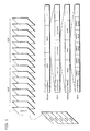
- FIG. 1 is a diagram illustrating an example data structure of a bitstream.
- the bitstream has a hierarchical structure such as below.
- the bitstream (Stream) is formed of more than one group of pictures (GOP).
- GOPs group of pictures
- Each GOP is made up of plural pictures, each of which is one of I picture, P picture, and B picture.
- Each picture is further made up of plural slices.
- Each slice which is a strip-shaped area within each picture, is made up of plural macroblocks.
- each stream, GOP, picture, and slice includes a synchronization signal (sync) for indicating the ending point of each unit and a header (header) which is data common to said each unit.
- the header and the data portion when data is carried not in a bitstream being a sequence of streams, but in a packet and the like being a piecemeal unit, the header and the data portion, which is the other part than the header, may be carried separately. In such a case, the header and the data portion shall not be incorporated into the same bitstream, as shown in FIG. 1 . In the case of a packet, however, even when the header and the data portion are not transmitted contiguously, it is simply that the header corresponding to the data portion is carried in another packet. Therefore, even when the header and the data portion are not incorporated into the same bitstream, the concept of a coded bitstream described with reference to FIG. 1 is also applicable to packets.
- the human sense of vision is more sensitive to the low frequency components than to the high frequency components. Furthermore, since the energy of the low frequency components in a picture signal is larger than that of the high frequency components, picture coding is performed in order from the low frequency components to the high frequency components. As a result, the number of bits required for coding the low frequency components is larger than that required for the high frequency components.
- the existing coding methods use larger quantization steps for the high frequency components than for the low frequency components when quantizing transformation coefficients, which are obtained by orthogonal transformation, of the respective frequencies.
- This technique has made it possible for the conventional coding methods to achieve a large increase in compression ratio with a small loss of picture quality from the standpoint of viewers.
- FIG. 2 shows an example quantization matrix.
- the upper left component is a direct current component
- rightward components are horizontal high frequency components
- downward components are vertical high frequency components.
- the quantization matrix in FIG. 2 also indicates that a larger quantization step is applied to a larger value.
- MPEG-4 AVC has been able to provide the potential to be used in various application domains.
- the versatility warrants the use of different sets of quantization matrices for different applications; different sets of quantization matrices for different color channels, etc.
- Encoders can select different quantization matrices depending on application or image to be coded. Because of that, we must develop an efficient quantization matrix definition and loading protocol to facilitate the flexible yet effective transmission of quantization matrix information.
- the present invention has been conceived in view of the above circumstances, and it is an object of the present invention to provide a video coding method according to claim 1.
- the article entitled "Quantization Tools for High Quality Video” published in the framework of ISO/IEC JTC1/SC29/WG11 and ITU-T SG16 Q.6 discloses that it is proposed to extend quantization to support high quality video using a weighting matrix and an extended quantization table.
- An encoder adaptively uses a weighting matrix and encodes it in a bitstream.
- a QP range is extended to -8 and new weighting matrices are formed.
- a weighting matrix is best transmitted out of band and through Parameter Sets in NAL.
- a weighting matrix should be changed higher than picture layer.
- the extension of the quantization table combined with the quantization matrix is necessary for high quality video coding.
- FIG. 3 is a block diagram showing the structure of a moving picture coding apparatus that embodies the moving picture coding method of the present invention.
- a picture coding apparatus 1 is an apparatus for performing compression coding on an input picture signal Vin and outputting a coded stream Str which has been coded into a bitstream by performing variable length coding and the like.
- such picture coding apparatus 3 is comprised of a motion estimation unit 101, a motion compensation unit 102, a subtraction unit 103, an orthogonal transformation unit 104, a quantization unit 105, an inverse quantization unit 106, an inverse orthogonal transformation unit 107, an addition unit 108, a picture memory 109, a switch 110, a variable length coding unit 111 and a quantization matrix holding unit 112.
- the picture signal Vin is inputted to the subtraction unit 103 and the motion estimation unit 101.
- the subtraction unit 103 calculates residual pixel values between each image in the input picture signal Vin and each predictive image, and outputs the calculated residual pixel values to the orthogonal transformation unit 104.
- the orthogonal transformation unit 104 transforms the residual pixel values into frequency coefficients, and outputs them to the quantization unit 105.
- the quantization unit 105 quantizes the inputted frequency coefficients using inputted quantization matrix WM, and outputs the resulting quantized values Qcoef to the variable length coding unit 111.
- the inverse quantization unit 106 performs inverse quantization on the quantized values Qcoef using the inputted quantization matrix WM, so as to turn them into the frequency coefficients, and outputs them to the inverse orthogonal transformation unit 107.
- the inverse orthogonal transformation unit 107 performs inverse frequency transformation on the frequency coefficients so as to transform them into residual pixel values, and outputs them to the addition unit 108.
- the addition unit 108 adds the residual pixel values and each predictive image outputted from the motion estimation unit 102, so as to form a decoded image.
- the switch 110 turns ON when it is indicated that such decoded image should be stored, and such decoded image is to be stored into the picture memory 109.
- the motion estimation unit 101 which receives the picture signal Vin on a macroblock basis, detects an image area closest to an image signal in such inputted picture signal Vin within a decoded picture stored in the picture memory 109, and determines motion vector(s) MV indicating the position of such area. Motion vectors are estimated for each block, which is obtained by further dividing a macroblock. When this is done, it is possible to use more than one picture as reference pictures. Here, since a plurality of pictures can be used as reference pictures, identification numbers (reference indices Index) to identify the respective reference pictures are required on a block-by-block basis. With the use of the reference indices Index, it is possible to identify each reference picture by associating each picture stored in the picture memory 109 with the picture number designated to such each picture.
- the motion compensation unit 102 selects, as a predictive image, the most suitable image area from among decoded pictures stored in the picture memory109, using the motion vectors detected in the above processing and the reference indices Index.
- the quantization matrix holding unit 112 holds the quantization matrix WM which has already been carried as a part of a parameter set and the matrix ID that identifies this quantization matrix WM in the manner in which they are associated with each other.
- the variable length coding unit 111 obtains, from the quantization matrix holding unit 112, the matrix ID corresponding to the quantization matrix WM used for quantization.
- the variable length coding unit 111 also performs variable length coding on the quantization values Qcoef, the matrix IDs, the reference indices Index, the picture types Ptype and the motion vectors MV so as to obtain a coded stream Str.
- FIG. 4 is a diagram showing the correspondence between sequence parameter sets and picture parameter sets and pictures.
- FIG. 5 is a diagram showing a part of a structure of a sequence parameter set
- FIG. 6 is a diagram showing a part of a structure of a picture parameter set. While a picture is made up of slices, all the slices included in the same picture have identifiers indicating the same picture parameter set.
- AVC In MPEG-4 AVC, there is no concept of a header, and common data is placed at the top of a sequence under the designation of a parameter set.
- a sequence parameter set SPS includes the number of pictures that are available as reference pictures, image size and the like
- a picture parameter set PPS includes a type of variable length coding (switching between Huffman coding and arithmetic coding), default values of quantization matrices, the number of reference pictures, and the like.
- An identifier is assigned to a sequence parameter set SPS, and to which sequence a picture belongs is identified by specifying this identifier in a picture parameter set PPS.
- An identifier is also assigned to a picture parameter set PPS, and which picture parameter set PPS is to be used is identified by specifying this identifier in a slice.
- sequence parameter set SPS and the picture parameter set PPS respectively include flags 501 and 601 indicating whether or not quantization matrices are carried as shown in FIG. 5 and FIG. 6 , and in the case where the quantization matrices are to be carried, quantization matrices 502 and 602 are respectively described therein.
- the quantization matrix can be changed adaptively to the unit of quantization (for example, horizontal 4 x vertical 4 pixels and horizontal 8 x vertical 8 pixels).
- FIG. 7 is a diagram showing an example description of quantization matrices in a parameter set.
- a picture signal Vin consists of luma components and two types of chroma components, it is possible to use different quantization matrices for luma components and two types of chroma components separately when performing quantization. It is also possible to use different quantization matrices for intra-picture coding and inter-picture coding separately.
- quantization matrices for a unit of quantization, luma components and two types of chroma components, and intra-picture coding and inter-picture coding, respectively.
- FIG. 8 is a flowchart showing the operations for placing a matrix ID.
- the variable length coding unit 111 obtains a quantization matrix WM used for quantization (Step S101). Next, the variable length coding unit 111 judges whether or not the obtained quantization matrix WM is held in the quantization matrix holding unit 112 (Step S102). Here, in the case whether the obtained quantization matrix WM is held in the quantization matrix holding unit 112 (YES in Step S102), the variable length coding unit 111 obtains the matrix ID corresponding to the obtained quantization matrix WM from the quantization matrix holding unit 112 (Step S103). Then, the variable length coding unit 111 places the obtained matrix ID in predetermined units (for example, per picture, slice or macroblock) (Step S104).
- predetermined units for example, per picture, slice or macroblock
- the quantization matrix holding unit 112 In the case where the obtained quantization matrix WM is not held in the quantization matrix holding unit 112 (NO in Step S102), the quantization matrix holding unit 112 generates the matrix ID for this quantization matrix WM (Step S105). Then, the quantization matrix holding unit 112 holds this quantization matrix WM and the matrix ID in the manner in which they are associated with each other (Step S106).
- the variable length coding unit 111 places the generated matrix ID in predetermined units (for example, per picture, slice or macroblock) (Step S107).
- the variable length coding unit 111 describes the generated matrix ID and the quantization matrix WM in the parameter set (Step S108). Note that the parameter set in which these matrix ID and quantization matrix WM are described is carried earlier, in a coded stream Str, than the predetermined units (that is, coded data quantized using this quantization matrix WM) to which this matrix ID is placed.
- quantization matrices WM are described in a parameter set and carried while only the matrix ID that identifies the quantization matrix WM used in predetermined units (for example, per picture, slice or macroblock) is placed therein, there is no need to describe the quantization matrix WM used in every predetermined unit. Therefore, it becomes possible to reduce the amount of data to be coded and achieve efficient coding.
- the default quantization matrix WM is replaced with the quantization matrix WM identified by the matrix ID according to the flag.
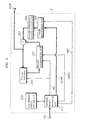
- FIG. 9 is a block diagram showing a structure of a moving picture decoding apparatus that embodies the moving picture decoding method according to the present invention.
- the moving picture decoding apparatus 2 is an apparatus that decodes a coded stream obtained by the coding by the moving picture coding apparatus 1 as described above, and includes a variable length decoding unit 201, a quantization matrix holding unit 202, a picture memory 203, a motion compensation unit 204, an inverse quantization unit 205, an inverse orthogonal transformation unit 206 and an addition unit 207.
- the variable length decoding unit 201 decodes the coded stream Str, and outputs quantized values Qcoef, reference indices Index, picture types Ptype and motion vectors MV.
- the variable length decoding unit 201 also decodes the coded stream, identifies a quantization matrix WM based on an extracted matrix ID, and outputs the identified quantization matrix WM.
- the quantization matrix holding unit 202 associates the quantization matrix WM which has already been carried in a parameter set with the matrix ID that identifies this quantization matrix WM, and holds them.
- the quantized values Qcoef, reference indices Index and motion vectors MV are inputted to the picture memory 203, the motion compensation unit 204 and the inverse quantization unit 205, and decoding processing is performed on them.
- the operations for the decoding are same as those in the moving picture coding apparatus 1 shown in FIG. 3 .
- FIG. 10 is a flowchart showing the operations for identifying a quantization matrix.
- the variable length decoding unit 201 decodes a coded stream Str and extracts a matrix ID placed in predetermined units (Step S201). Next, the variable length decoding unit 201 identifies a quantization matrix WM from among quantization matrices held in the quantization matrix holding unit 202, based on the extracted matrix ID (Step S202). Then, the variable length decoding unit 201 outputs the identified quantization matrix WM to the inverse quantization unit 205 (Step S203).
- quantization matrices WM are described in a parameter set and carried, it is possible, in predetermined units (for example, per picture, per slice or per macroblock), to decode a coded stream in which only the matrix ID that identifies the used quantization matrix WM is placed.
- quantization matrices WM are described in a parameter set and carried in the present embodiment but the present invention is not limited to such case.
- quantization matrices may be previously transmitted separately from a coded stream.
- a picture signal Vin is made up of luma components and two types of chroma components as described above, it is possible to use different quantization matrices separately for luma components and two types of chroma components for quantization. It is also possible to use an uniform quantization matrix for all the components.
- FIG. 11 is a flowchart showing the operations for identifying quantization matrices to be used for chroma components.
- the variable length decoding unit 201 judges whether or not there is a quantization matrix for chroma components of the type corresponding to the current decoding among the quantization matrices WM identified as mentioned above (Step S301). For example, in the case where a quantized value Qcoef to be decoded is a first chroma component, it judges whether or not there is a quantization matrix for the first chroma components. In the case where a quantized value Qcoef to be decoded is a second chroma component, it judges whether or not there is a quantization matrix for the second chroma components.
- Step S301 if there is a quantization matrix for the corresponding type of chroma components (YES in Step S301), it outputs the corresponding chroma quantization matrix to the inverse quantization unit 205 as a matrix to be used (Step S302).
- the variable length decoding unit 201 judges whether or not there is a quantization matrix for another type of chroma components (Step S303). For example, in the case where a quantized value Qcoef to be decoded is a first chroma component, it judges whether or not there is a quantization matrix for the second chroma components. In the case where a quantized value Qcoef to be decoded is a second chroma component, it judges whether or not there is a quantization matrix for the first chroma components.
- Step S303 if there is a corresponding quantization matrix for another type of chroma components (YES in Step S303), it outputs the quantization matrix for another type of chroma components to the inverse quantization unit 205 as a matrix to be used (Step S304). On the other hand, if there is no quantization matrix for another type of chroma components (NO in Step S303), it outputs the quantization matrix for the luma components to the inverse quantization unit 205 as a matrix to be used (Step S305).
- the moving picture coding method and the moving picture decoding method according to the present invention are useful as methods for coding pictures that make up a moving picture so as to generate a coded stream and for decoding the generated coded stream, in devices such as a cellular phone, a DVD device and a personal computer.
Description
- The present invention relates to a moving picture coding method for coding moving pictures and generating streams and a moving picture decoding method for decoding such coded streams, as well as the streams.
- In the age of multimedia which integrally handles audio, video and other pixel values, existing information media, i.e., newspaper, magazine, television, radio, telephone and other means through which information is conveyed to people, have recently come to be included in the scope of multimedia. Generally, multimedia refers to something that is represented by associating not only characters, but also graphics, audio, and especially pictures and the like together. However, in order to include the aforementioned existing information media into the scope of multimedia, it appears as a prerequisite to represent such information in digital form.
- However, when calculating the amount of information contained in each of the aforementioned information media as the amount of digital information, while the amount of information per character is 1 to 2 bytes in the case of characters, the amount of information to be required is 64Kbits per second in the case of audio (telephone quality), and 100Mbits per second in the case of moving pictures (current television reception quality). Therefore, it is not realistic for the aforementioned information media to handle such an enormous amount of information as it is in digital form. For example, although video phones are already in the actual use by using Integrated Services Digital Network (ISDN) which offers a transmission speed of 64Kbits/s to 1.5Mbits/s, it is not practical to transmit video of televisions and cameras directly through ISDN.
- Against this backdrop, information compression techniques have become required, and moving picture compression techniques compliant with H.261 and H.263 standards recommended by ITU-T (International Telecommunication Union - Telecommunication Standardization Sector) are employed for video phones, for example. Moreover, according to information compression techniques compliant with the MPEG-1 standard, it is possible to store picture information into an ordinary music CD (compact disc) together with sound information.
- Here, MPEG (Moving Picture Experts Group) is an international standard on compression of moving picture signals standardized by ISO/IEC (International Organization for Standardization, International Electrotechnical Commission), and MPEG-1 is a standard for compressing television signal information approximately into one hundredth so that moving picture signals can be transmitted at a rate of 1.5 Mbit/s. Furthermore, since a transmission speed achieved by the MPEG-1 standard is a middle-quality speed of about 1.5Mbit/s, MPEG-2, which was standardized with a view to satisfying requirements for further improved picture quality, allows data transmission equivalent in quality to television broadcasting through which moving picture signals are transmitted at a rate of 2 to 15Mbit/s. Moreover, MPEG-4 was standardized by the working group (ISO/IEC JTC1/SC29/WG11) which promoted the standardization of MPEG-1 and MPEG-2. MPEG-4, which provides a higher compression ratio than that of MPEG-1 and MPEG-2 and which enables an object-based coding/decoding/operation, is capable of providing a new functionality required in this age of multimedia. At the beginning stage of standardization, MPEG-4 aimed at providing a low bit rate coding method, but it has been extended as a standard supporting more general coding that handles interlaced images as well as high bit rate coding. Currently, an effort has been made jointly by ISO/IEC and ITU-T for standardizing MPEG-4 AVC and ITU-T H.264 as picture coding methods of the next generation that offer a higher compression ratio. As of August 2002, a committee draft (CD) is issued for a picture coding method of the next generation.
- In general, in coding of a moving picture, the amount of information is compressed by reducing redundancies in temporal and spatial directions. Therefore, in inter picture prediction coding aiming at reducing temporal redundancies, motion estimation and generation of a predicative image are carried out on a block-by-block basis with reference to forward or backward picture(s), and coding is then performed on the difference value between the obtained predictive image and an image in the current picture to be coded. Here, "picture" is a term denoting one image. In the case of a progressive image, "picture" means a frame, whereas it means a frame or fields in the case of an interlaced image. Here, "interlaced image" is an image of a frame composed of two fields which are separated in capture time. In coding and decoding of an interlaced image, it is possible to handle one frame as a frame as it is, as two fields, or as a frame structure or a field structure on a per-block basis within the frame.
- A picture to be coded using intra picture prediction without reference to any pictures shall be referred to as an I picture. A picture to be coded using inter picture prediction with reference to only one picture shall be referred to as a P picture. And, a picture to be coded using inter picture prediction with reference to two pictures at the same time shall be referred to as a B picture. It is possible for a B picture to refer to two pictures which can be arbitrarily combined from forward/backward pictures in display order. Reference images (reference pictures) can be determined for each block serving as a basic coding/decoding unit. Distinction shall be made between such reference pictures by calling a reference picture to be described earlier in a coded bitstream as a first reference picture, and by calling a reference picture to be described later in the bitstream as a second reference picture. Note that as a condition for coding and decoding these types of pictures, pictures used for reference are required to be already coded and decoded.
- P pictures and B pictures are coded using motion compensated inter picture prediction. Coding by use of motion compensated inter picture prediction is a coding method that employs motion compensation in inter picture prediction coding. Unlike a method for performing prediction simply based on pixel values in a reference picture, motion estimation is a technique capable of improving prediction accuracy as well as reducing the amount of data by estimating the amount of motion (hereinafter referred to as "motion vector") of each part within a picture and further by performing prediction in consideration of such amount of motion. For example, it is possible to reduce the amount of data through motion compensation by estimating motion vectors of the current picture to be coded and then by coding prediction residuals between prediction values obtained by shifting only the amount of the respective motion vectors and the current picture to be coded. In this technique, motion vectors are also recorded or transmitted in coded form, since motion vector information is required at the time of decoding.
- Motion vectors are estimated on a per-macroblock basis. More specifically, a macroblock shall be previously fixed in the current picture to be coded, so as to estimate motion vectors by finding the position of the most similar reference block of such fixed macroblock within the search area in a reference picture.
-
FIG. 1 is a diagram illustrating an example data structure of a bitstream. AsFIG. 1 shows, the bitstream has a hierarchical structure such as below. The bitstream (Stream) is formed of more than one group of pictures (GOP). By using GOPs as basic coding units, it becomes possible to edit a moving picture as well as to make a random access. Each GOP is made up of plural pictures, each of which is one of I picture, P picture, and B picture. Each picture is further made up of plural slices. Each slice, which is a strip-shaped area within each picture, is made up of plural macroblocks. Moreover, each stream, GOP, picture, and slice includes a synchronization signal (sync) for indicating the ending point of each unit and a header (header) which is data common to said each unit. - Note that when data is carried not in a bitstream being a sequence of streams, but in a packet and the like being a piecemeal unit, the header and the data portion, which is the other part than the header, may be carried separately. In such a case, the header and the data portion shall not be incorporated into the same bitstream, as shown in
FIG. 1 . In the case of a packet, however, even when the header and the data portion are not transmitted contiguously, it is simply that the header corresponding to the data portion is carried in another packet. Therefore, even when the header and the data portion are not incorporated into the same bitstream, the concept of a coded bitstream described with reference toFIG. 1 is also applicable to packets. - Generally speaking, the human sense of vision is more sensitive to the low frequency components than to the high frequency components. Furthermore, since the energy of the low frequency components in a picture signal is larger than that of the high frequency components, picture coding is performed in order from the low frequency components to the high frequency components. As a result, the number of bits required for coding the low frequency components is larger than that required for the high frequency components.
- In view of the above points, the existing coding methods use larger quantization steps for the high frequency components than for the low frequency components when quantizing transformation coefficients, which are obtained by orthogonal transformation, of the respective frequencies. This technique has made it possible for the conventional coding methods to achieve a large increase in compression ratio with a small loss of picture quality from the standpoint of viewers.
- Meanwhile, since quantization step sizes of the high frequency components with regard to the low frequency components depend on picture signal, a technique for changing the sizes of quantization steps for the respective frequency components on a picture-by-picture basis has been conventionally employed. A quantization matrix is used to derive quantization steps of the respective frequency components.
FIG. 2 shows an example quantization matrix. In this drawing, the upper left component is a direct current component, whereas rightward components are horizontal high frequency components and downward components are vertical high frequency components. The quantization matrix inFIG. 2 also indicates that a larger quantization step is applied to a larger value. Usually, it is possible to use different quantization matrices for each picture, and the matrix to be used is described in each picture header. Therefore, even if the same quantization matrix is used for all the pictures, it is described in each picture header and carried one by one. - Meanwhile, current MPEG-4 AVC does not include quantization matrix as in MPEG-2 and MPEG-4. This results in difficulty in achieving optimal subjective quality in the current MPEG-4 AVC coding scheme and other schemes using uniform quantization in all DCT or DCT-like coefficients. When such quantization matrix scheme is introduced, we have to allow the current provision of MPEG-4 AVC or other standards to carry the quantization matrices, in consideration of compatibility with the existing standards.
- Additionally, because of the coding efficiency improvement, MPEG-4 AVC has been able to provide the potential to be used in various application domains. The versatility warrants the use of different sets of quantization matrices for different applications; different sets of quantization matrices for different color channels, etc. Encoders can select different quantization matrices depending on application or image to be coded. Because of that, we must develop an efficient quantization matrix definition and loading protocol to facilitate the flexible yet effective transmission of quantization matrix information.
- The present invention has been conceived in view of the above circumstances, and it is an object of the present invention to provide a video coding method according to
claim 1. - The article entitled "Quantization Tools for High Quality Video" published in the framework of ISO/IEC JTC1/SC29/WG11 and ITU-T SG16 Q.6 discloses that it is proposed to extend quantization to support high quality video using a weighting matrix and an extended quantization table. An encoder adaptively uses a weighting matrix and encodes it in a bitstream. A QP range is extended to -8 and new weighting matrices are formed. A weighting matrix is best transmitted out of band and through Parameter Sets in NAL. A weighting matrix should be changed higher than picture layer. The extension of the quantization table combined with the quantization matrix is necessary for high quality video coding.
- The article entitled "New Quantization Tools" published in the framework of ISO/IEC JTC1/SC29/WG11 deals with similar subject matter and discloses that in attempting to standardize new video coding technology, testing demonstrated that with respect to supporting high video quality, several problems exist that come from quantization.
- These and other objects, advantages and features of the invention will become apparent from the following description thereof taken in conjunction with the accompanying drawings that illustrate a specific embodiment of the invention. In the Drawings:
-
FIG. 1 is a diagram illustrating an example data structure of a bitstream; -
FIG. 2 is a diagram showing an example quantization matrix; -
FIG. 3 is a block diagram showing a structure of a moving picture coding apparatus that embodies the moving picture coding method according to the present invention; -
FIG. 4 is a diagram showing correspondence between sequence parameter sets and picture parameter sets and pictures; -
FIG. 5 is a diagram showing a part of a structure of a sequence parameter set; -
FIG. 6 is a diagram showing a part of a structure of a picture parameter set; -
FIG. 7 is a diagram showing an example description of quantization matrices in a parameter set; -
FIG. 8 is a flowchart showing operations for placing a matrix ID; -
FIG. 9 is a block diagram showing a structure of a moving picture decoding apparatus that embodies the moving picture decoding method according to the present invention; -
FIG. 10 is a flowchart showing operations for identifying a quantization matrix; -
FIG. 11 is a flowchart showing operations for identifying a quantization matrix to be used for chroma components; -
FIG. 12 is a diagram showing correspondence between quantization matrices carried as separate data and quantization matrices to be used for sequences; -
FIGs. 13A to 13C are diagrams illustrating a recording medium that stores a program for realizing, by a computer system, the moving picture coding method and the moving picture decoding method according to the above embodiments, and particularly,FIG. 13A is a diagram illustrating an example physical format of a flexible disk as a main body of a recording medium,FIG. 13B is a full appearance of the flexible disk viewed from the front thereof, a cross-sectional view thereof and the flexible disk itself, andFIG. 13C is a diagram illustrating a structure for recording and reproducing the above program on and from the flexible disk; -
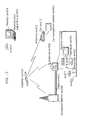
FIG. 14 is a block diagram showing an overall configuration of a content supply system that embodies a content distribution service; -
FIG. 15 is a diagram showing an example of a cellular phone; -
FIG. 16 is a block diagram showing an inner structure of the cellular phone; and -
FIG. 17 is a diagram showing an overall configuration of a digital broadcasting system. - The embodiments of the present invention are described by referring to diagrams.
-
FIG. 3 is a block diagram showing the structure of a moving picture coding apparatus that embodies the moving picture coding method of the present invention. - A
picture coding apparatus 1 is an apparatus for performing compression coding on an input picture signal Vin and outputting a coded stream Str which has been coded into a bitstream by performing variable length coding and the like. As shown inFIG. 3 , suchpicture coding apparatus 3 is comprised of amotion estimation unit 101, amotion compensation unit 102, asubtraction unit 103, anorthogonal transformation unit 104, aquantization unit 105, aninverse quantization unit 106, an inverseorthogonal transformation unit 107, anaddition unit 108, apicture memory 109, aswitch 110, a variablelength coding unit 111 and a quantizationmatrix holding unit 112. - The picture signal Vin is inputted to the
subtraction unit 103 and themotion estimation unit 101. Thesubtraction unit 103 calculates residual pixel values between each image in the input picture signal Vin and each predictive image, and outputs the calculated residual pixel values to theorthogonal transformation unit 104. Theorthogonal transformation unit 104 transforms the residual pixel values into frequency coefficients, and outputs them to thequantization unit 105. Thequantization unit 105 quantizes the inputted frequency coefficients using inputted quantization matrix WM, and outputs the resulting quantized values Qcoef to the variablelength coding unit 111. - The
inverse quantization unit 106 performs inverse quantization on the quantized values Qcoef using the inputted quantization matrix WM, so as to turn them into the frequency coefficients, and outputs them to the inverseorthogonal transformation unit 107. The inverseorthogonal transformation unit 107 performs inverse frequency transformation on the frequency coefficients so as to transform them into residual pixel values, and outputs them to theaddition unit 108. Theaddition unit 108 adds the residual pixel values and each predictive image outputted from themotion estimation unit 102, so as to form a decoded image. Theswitch 110 turns ON when it is indicated that such decoded image should be stored, and such decoded image is to be stored into thepicture memory 109. - Meanwhile, the
motion estimation unit 101, which receives the picture signal Vin on a macroblock basis, detects an image area closest to an image signal in such inputted picture signal Vin within a decoded picture stored in thepicture memory 109, and determines motion vector(s) MV indicating the position of such area. Motion vectors are estimated for each block, which is obtained by further dividing a macroblock. When this is done, it is possible to use more than one picture as reference pictures. Here, since a plurality of pictures can be used as reference pictures, identification numbers (reference indices Index) to identify the respective reference pictures are required on a block-by-block basis. With the use of the reference indices Index, it is possible to identify each reference picture by associating each picture stored in thepicture memory 109 with the picture number designated to such each picture. - The
motion compensation unit 102 selects, as a predictive image, the most suitable image area from among decoded pictures stored in the picture memory109, using the motion vectors detected in the above processing and the reference indices Index. - The quantization
matrix holding unit 112 holds the quantization matrix WM which has already been carried as a part of a parameter set and the matrix ID that identifies this quantization matrix WM in the manner in which they are associated with each other. - The variable
length coding unit 111 obtains, from the quantizationmatrix holding unit 112, the matrix ID corresponding to the quantization matrix WM used for quantization. The variablelength coding unit 111 also performs variable length coding on the quantization values Qcoef, the matrix IDs, the reference indices Index, the picture types Ptype and the motion vectors MV so as to obtain a coded stream Str. -
FIG. 4 is a diagram showing the correspondence between sequence parameter sets and picture parameter sets and pictures.FIG. 5 is a diagram showing a part of a structure of a sequence parameter set, andFIG. 6 is a diagram showing a part of a structure of a picture parameter set. While a picture is made up of slices, all the slices included in the same picture have identifiers indicating the same picture parameter set. - In MPEG-4 AVC, there is no concept of a header, and common data is placed at the top of a sequence under the designation of a parameter set. There are two types of parameter sets, a picture parameter set PPS that is data corresponding to the header of each picture, and a sequence parameter set SPS corresponding to the header of a GOP or a sequence in MPEG-2. A sequence parameter set SPS includes the number of pictures that are available as reference pictures, image size and the like, while a picture parameter set PPS includes a type of variable length coding (switching between Huffman coding and arithmetic coding), default values of quantization matrices, the number of reference pictures, and the like.
- An identifier is assigned to a sequence parameter set SPS, and to which sequence a picture belongs is identified by specifying this identifier in a picture parameter set PPS. An identifier is also assigned to a picture parameter set PPS, and which picture parameter set PPS is to be used is identified by specifying this identifier in a slice.
- For example, in the example shown in
FIG. 4 , apicture # 1 includes the identifier (PPS=1) of a picture parameter set PPS to be referred to by a slice included in thepicture # 1. The picture parameter setPPS # 1 includes the identifier (SPS=1) of a sequence parameter set to be referred to. - Furthermore, the sequence parameter set SPS and the picture parameter set PPS respectively include
flags FIG. 5 andFIG. 6 , and in the case where the quantization matrices are to be carried,quantization matrices - The quantization matrix can be changed adaptively to the unit of quantization (for example, horizontal 4 x vertical 4 pixels and horizontal 8 x vertical 8 pixels).
-
FIG. 7 is a diagram showing an example description of quantization matrices in a parameter set. - Since a picture signal Vin consists of luma components and two types of chroma components, it is possible to use different quantization matrices for luma components and two types of chroma components separately when performing quantization. It is also possible to use different quantization matrices for intra-picture coding and inter-picture coding separately.
- Therefore, for example, as shown in
FIG. 7 , it is possible to describe quantization matrices for a unit of quantization, luma components and two types of chroma components, and intra-picture coding and inter-picture coding, respectively. - The operations for placing matrix IDs in the above-structured moving picture coding apparatus are explained.
FIG. 8 is a flowchart showing the operations for placing a matrix ID. - The variable
length coding unit 111 obtains a quantization matrix WM used for quantization (Step S101). Next, the variablelength coding unit 111 judges whether or not the obtained quantization matrix WM is held in the quantization matrix holding unit 112 (Step S102). Here, in the case whether the obtained quantization matrix WM is held in the quantization matrix holding unit 112 (YES in Step S102), the variablelength coding unit 111 obtains the matrix ID corresponding to the obtained quantization matrix WM from the quantization matrix holding unit 112 (Step S103). Then, the variablelength coding unit 111 places the obtained matrix ID in predetermined units (for example, per picture, slice or macroblock) (Step S104). - On the other hand, in the case where the obtained quantization matrix WM is not held in the quantization matrix holding unit 112 (NO in Step S102), the quantization
matrix holding unit 112 generates the matrix ID for this quantization matrix WM (Step S105). Then, the quantizationmatrix holding unit 112 holds this quantization matrix WM and the matrix ID in the manner in which they are associated with each other (Step S106). The variablelength coding unit 111 places the generated matrix ID in predetermined units (for example, per picture, slice or macroblock) (Step S107). The variablelength coding unit 111 describes the generated matrix ID and the quantization matrix WM in the parameter set (Step S108). Note that the parameter set in which these matrix ID and quantization matrix WM are described is carried earlier, in a coded stream Str, than the predetermined units (that is, coded data quantized using this quantization matrix WM) to which this matrix ID is placed. - As described above, since quantization matrices WM are described in a parameter set and carried while only the matrix ID that identifies the quantization matrix WM used in predetermined units (for example, per picture, slice or macroblock) is placed therein, there is no need to describe the quantization matrix WM used in every predetermined unit. Therefore, it becomes possible to reduce the amount of data to be coded and achieve efficient coding.
- Note that it is possible to update a quantization matrix WM carried in a sequence parameter set SPS and carry the updated one (with the same matrix ID) in a picture parameter set PPS. In this case, the updated quantization matrix WM is used only when the picture parameter set PPS is referenced.
- It is also possible to include in a coded stream a flag indicating switching between the default quantization matrix WM and the quantization matrix WM identified by a matrix ID. In this case, the default quantization matrix WM is replaced with the quantization matrix WM identified by the matrix ID according to the flag.
-
FIG. 9 is a block diagram showing a structure of a moving picture decoding apparatus that embodies the moving picture decoding method according to the present invention. - The moving
picture decoding apparatus 2 is an apparatus that decodes a coded stream obtained by the coding by the movingpicture coding apparatus 1 as described above, and includes a variablelength decoding unit 201, a quantizationmatrix holding unit 202, apicture memory 203, amotion compensation unit 204, aninverse quantization unit 205, an inverseorthogonal transformation unit 206 and anaddition unit 207. - The variable
length decoding unit 201 decodes the coded stream Str, and outputs quantized values Qcoef, reference indices Index, picture types Ptype and motion vectors MV. The variablelength decoding unit 201 also decodes the coded stream, identifies a quantization matrix WM based on an extracted matrix ID, and outputs the identified quantization matrix WM. - The quantization
matrix holding unit 202 associates the quantization matrix WM which has already been carried in a parameter set with the matrix ID that identifies this quantization matrix WM, and holds them. - The quantized values Qcoef, reference indices Index and motion vectors MV are inputted to the
picture memory 203, themotion compensation unit 204 and theinverse quantization unit 205, and decoding processing is performed on them. The operations for the decoding are same as those in the movingpicture coding apparatus 1 shown inFIG. 3 . - Next, the operations for identifying a quantization matrix in the above-structured moving picture decoding apparatus are explained.
FIG. 10 is a flowchart showing the operations for identifying a quantization matrix. - The variable
length decoding unit 201 decodes a coded stream Str and extracts a matrix ID placed in predetermined units (Step S201). Next, the variablelength decoding unit 201 identifies a quantization matrix WM from among quantization matrices held in the quantizationmatrix holding unit 202, based on the extracted matrix ID (Step S202). Then, the variablelength decoding unit 201 outputs the identified quantization matrix WM to the inverse quantization unit 205 (Step S203). - As described above, while a quantization matrices WM are described in a parameter set and carried, it is possible, in predetermined units (for example, per picture, per slice or per macroblock), to decode a coded stream in which only the matrix ID that identifies the used quantization matrix WM is placed.
- Note that quantization matrices WM are described in a parameter set and carried in the present embodiment but the present invention is not limited to such case. For example, quantization matrices may be previously transmitted separately from a coded stream.
- By the way, since a picture signal Vin is made up of luma components and two types of chroma components as described above, it is possible to use different quantization matrices separately for luma components and two types of chroma components for quantization. It is also possible to use an uniform quantization matrix for all the components.
- Next, the operations for identifying quantization matrices to be used for chroma components are explained.
FIG. 11 is a flowchart showing the operations for identifying quantization matrices to be used for chroma components. - The variable
length decoding unit 201 judges whether or not there is a quantization matrix for chroma components of the type corresponding to the current decoding among the quantization matrices WM identified as mentioned above (Step S301). For example, in the case where a quantized value Qcoef to be decoded is a first chroma component, it judges whether or not there is a quantization matrix for the first chroma components. In the case where a quantized value Qcoef to be decoded is a second chroma component, it judges whether or not there is a quantization matrix for the second chroma components. Here, if there is a quantization matrix for the corresponding type of chroma components (YES in Step S301), it outputs the corresponding chroma quantization matrix to theinverse quantization unit 205 as a matrix to be used (Step S302). - On the other hand, if there is no such corresponding chroma quantization matrix (NO in Step S301), the variable
length decoding unit 201 judges whether or not there is a quantization matrix for another type of chroma components (Step S303). For example, in the case where a quantized value Qcoef to be decoded is a first chroma component, it judges whether or not there is a quantization matrix for the second chroma components. In the case where a quantized value Qcoef to be decoded is a second chroma component, it judges whether or not there is a quantization matrix for the first chroma components. Here, if there is a corresponding quantization matrix for another type of chroma components (YES in Step S303), it outputs the quantization matrix for another type of chroma components to theinverse quantization unit 205 as a matrix to be used (Step S304). On the other hand, if there is no quantization matrix for another type of chroma components (NO in Step S303), it outputs the quantization matrix for the luma components to theinverse quantization unit 205 as a matrix to be used (Step S305). - As a result, it becomes possible to decode a coded stream even if there is no chroma quantization matrix.
- As described above, the moving picture coding method and the moving picture decoding method according to the present invention are useful as methods for coding pictures that make up a moving picture so as to generate a coded stream and for decoding the generated coded stream, in devices such as a cellular phone, a DVD device and a personal computer.
Claims (3)
- A moving picture coding and decoding method which includes a moving picture coding method for coding a moving picture and a moving picture decoding method for decoding a coded picture,
wherein said moving picture coding method comprises the steps of:generating a matrix ID for identifying a quantization matrix different from a default quantization matrix;coding the quantization matrix identified by the generated matrix ID, the quantization matrix being coded in association with the matrix ID;coding a current picture by using the quantization matrix, to generate data of the coded current picture; andadding the matrix ID identifying the quantization matrix used in the coding of the current picture, to the data of the coded current picture,wherein said moving picture decoding method comprises the steps of:obtaining, from a coded stream, a quantization matrix other than a default quantization matrix and a matrix ID for identifying the quantization matrix, and holding the quantization matrix and the matrix ID;extracting, from the coded stream, a matrix ID which is added to data generated by coding a current picture and is used for identifying a quantization matrix that has been used to code the current picture;identifying, from the quantization matrices held in said holding, a quantization matrix corresponding to the matrix ID; anddecoding the data of the current picture using the identified quantization matrix,wherein each picture is made up of a luma component, a first chroma component and a second chroma component, and the picture decoding method is characterized in that it comprises the following steps,a first step, wherein in the case where there are a quantization matrix for the luma component, a quantization matrix for the first chroma component, and a quantization matrix for the second chroma component, separately, in the quantization matrix identified by the extracted matrix ID, the quantization matrix for the luma component is identified as a quantization matrix for a luma component of the current picture, the quantization matrix for the first chroma component is identified as a quantization matrix for a first chroma component of the current picture, and the quantization matrix for the second chroma component is identified as a quantization matrix for a second chroma component of the current picture,a second step, wherein in the case where the quantization matrix for the first component is not present and the quantization matrix for the second chroma component is present in the quantization matrix identified by the extracted matrix ID, the quantization matrix for the second component is identified, instead of the default quantization matrix, as the quantization matrix for the first chroma component of the current picture, anda third step, wherein in the case where the both of the quantization matrix for the first component and the quantization matrix for the second chroma component are not present in the quantization matrix identified by the extracted matrix ID, the quantization matrix for the luma component is identified, instead of the default quantization matrix, as the quantization matrix for the first chroma component and the second chroma component of the current picture. - The moving picture coding and decoding method according to Claim 1,
wherein the matrix ID is added to the data of the coded current picture, per picture, slice, or macroblock. - The moving picture coding and decoding method according to Claim 1,
wherein the quantization matrix is coded per a plurality of pictures, or per a single slice.
Priority Applications (1)
| Application Number | Priority Date | Filing Date | Title |
|---|---|---|---|
| PL11175220T PL2384002T3 (en) | 2004-01-30 | 2005-01-26 | Moving picture decoding method using additional quantization matrices |
Applications Claiming Priority (4)
| Application Number | Priority Date | Filing Date | Title |
|---|---|---|---|
| US54049904P | 2004-01-30 | 2004-01-30 | |
| US55290704P | 2004-03-12 | 2004-03-12 | |
| US56135104P | 2004-04-12 | 2004-04-12 | |
| EP05712072A EP1709801B1 (en) | 2004-01-30 | 2005-01-26 | Video Decoding Method Using Adaptive Quantization Matrices |
Related Parent Applications (3)
| Application Number | Title | Priority Date | Filing Date |
|---|---|---|---|
| EP05712072A Division-Into EP1709801B1 (en) | 2004-01-30 | 2005-01-26 | Video Decoding Method Using Adaptive Quantization Matrices |
| EP05712072A Division EP1709801B1 (en) | 2004-01-30 | 2005-01-26 | Video Decoding Method Using Adaptive Quantization Matrices |
| EP05712072.7 Division | 2005-01-26 |
Publications (2)
| Publication Number | Publication Date |
|---|---|
| EP2384002A1 EP2384002A1 (en) | 2011-11-02 |
| EP2384002B1 true EP2384002B1 (en) | 2016-01-13 |
Family
ID=34841730
Family Applications (2)
| Application Number | Title | Priority Date | Filing Date |
|---|---|---|---|
| EP11175220.0A Active EP2384002B1 (en) | 2004-01-30 | 2005-01-26 | Moving picture decoding method using additional quantization matrices |
| EP05712072A Active EP1709801B1 (en) | 2004-01-30 | 2005-01-26 | Video Decoding Method Using Adaptive Quantization Matrices |
Family Applications After (1)
| Application Number | Title | Priority Date | Filing Date |
|---|---|---|---|
| EP05712072A Active EP1709801B1 (en) | 2004-01-30 | 2005-01-26 | Video Decoding Method Using Adaptive Quantization Matrices |
Country Status (8)
| Country | Link |
|---|---|
| US (8) | US7933327B2 (en) |
| EP (2) | EP2384002B1 (en) |
| JP (3) | JP4679524B2 (en) |
| KR (1) | KR101065998B1 (en) |
| CN (2) | CN101699866B (en) |
| ES (2) | ES2563295T3 (en) |
| PL (2) | PL2384002T3 (en) |
| WO (1) | WO2005076614A1 (en) |
Families Citing this family (68)
| Publication number | Priority date | Publication date | Assignee | Title |
|---|---|---|---|---|
| US6882685B2 (en) | 2001-09-18 | 2005-04-19 | Microsoft Corporation | Block transform and quantization for image and video coding |
| PL2384002T3 (en) * | 2004-01-30 | 2016-07-29 | Panasonic Ip Corp America | Moving picture decoding method using additional quantization matrices |
| EP1610560A1 (en) * | 2004-06-24 | 2005-12-28 | Deutsche Thomson-Brandt Gmbh | Method and apparatus for generating and for decoding coded picture data |
| US8422546B2 (en) | 2005-05-25 | 2013-04-16 | Microsoft Corporation | Adaptive video encoding using a perceptual model |
| US20060291565A1 (en) * | 2005-06-22 | 2006-12-28 | Chen Eddie Y | System and method for performing video block prediction |
| JP2009527186A (en) * | 2006-02-17 | 2009-07-23 | トムソン ライセンシング | Local weighted prediction for brightness change of video data |
| ES2612950T3 (en) * | 2006-03-16 | 2017-05-19 | Huawei Technologies Co., Ltd. | A method and a device for quantification in coding-decoding |
| US8130828B2 (en) | 2006-04-07 | 2012-03-06 | Microsoft Corporation | Adjusting quantization to preserve non-zero AC coefficients |
| US7995649B2 (en) | 2006-04-07 | 2011-08-09 | Microsoft Corporation | Quantization adjustment based on texture level |
| US7974340B2 (en) * | 2006-04-07 | 2011-07-05 | Microsoft Corporation | Adaptive B-picture quantization control |
| US8059721B2 (en) | 2006-04-07 | 2011-11-15 | Microsoft Corporation | Estimating sample-domain distortion in the transform domain with rounding compensation |
| US20070237237A1 (en) * | 2006-04-07 | 2007-10-11 | Microsoft Corporation | Gradient slope detection for video compression |
| US8503536B2 (en) * | 2006-04-07 | 2013-08-06 | Microsoft Corporation | Quantization adjustments for DC shift artifacts |
| US8711925B2 (en) * | 2006-05-05 | 2014-04-29 | Microsoft Corporation | Flexible quantization |
| US20080170793A1 (en) * | 2007-01-12 | 2008-07-17 | Mitsubishi Electric Corporation | Image encoding device and image encoding method |
| JP2008193627A (en) * | 2007-01-12 | 2008-08-21 | Mitsubishi Electric Corp | Image encoding device, image decoding device, image encoding method, and image decoding method |
| US8238424B2 (en) | 2007-02-09 | 2012-08-07 | Microsoft Corporation | Complexity-based adaptive preprocessing for multiple-pass video compression |
| US8942289B2 (en) | 2007-02-21 | 2015-01-27 | Microsoft Corporation | Computational complexity and precision control in transform-based digital media codec |
| US20080240257A1 (en) * | 2007-03-26 | 2008-10-02 | Microsoft Corporation | Using quantization bias that accounts for relations between transform bins and quantization bins |
| US8498335B2 (en) | 2007-03-26 | 2013-07-30 | Microsoft Corporation | Adaptive deadzone size adjustment in quantization |
| US8243797B2 (en) | 2007-03-30 | 2012-08-14 | Microsoft Corporation | Regions of interest for quality adjustments |
| US20080253449A1 (en) * | 2007-04-13 | 2008-10-16 | Yoji Shimizu | Information apparatus and method |
| US8442337B2 (en) * | 2007-04-18 | 2013-05-14 | Microsoft Corporation | Encoding adjustments for animation content |
| US8331438B2 (en) | 2007-06-05 | 2012-12-11 | Microsoft Corporation | Adaptive selection of picture-level quantization parameters for predicted video pictures |
| KR101228020B1 (en) * | 2007-12-05 | 2013-01-30 | 삼성전자주식회사 | Video coding method and apparatus using side matching, and video decoding method and appartus thereof |
| US8189933B2 (en) * | 2008-03-31 | 2012-05-29 | Microsoft Corporation | Classifying and controlling encoding quality for textured, dark smooth and smooth video content |
| US8897359B2 (en) | 2008-06-03 | 2014-11-25 | Microsoft Corporation | Adaptive quantization for enhancement layer video coding |
| JP2010288166A (en) * | 2009-06-15 | 2010-12-24 | Panasonic Corp | Moving picture encoder, broadcast wave recorder, and program |
| JP2011029956A (en) * | 2009-07-27 | 2011-02-10 | Sony Corp | Image encoding device and image encoding method |
| JP5282692B2 (en) * | 2009-07-27 | 2013-09-04 | ソニー株式会社 | Image coding apparatus and image coding method |
| KR20110017303A (en) * | 2009-08-13 | 2011-02-21 | 삼성전자주식회사 | Method and apparatus for encoding and decoding image by using rotational transform |
| KR101504887B1 (en) | 2009-10-23 | 2015-03-24 | 삼성전자 주식회사 | Method and apparatus for video decoding by individual parsing or decoding in data unit level, and method and apparatus for video encoding for individual parsing or decoding in data unit level |
| JPWO2011052215A1 (en) * | 2009-10-30 | 2013-03-14 | パナソニック株式会社 | Decoding method, decoding device, encoding method, and encoding device |
| US9467710B2 (en) * | 2009-10-30 | 2016-10-11 | Sun Patent Trust | Image decoding method, image coding method, image decoding apparatus, image coding apparatus, program, and integrated circuit |
| KR101457396B1 (en) | 2010-01-14 | 2014-11-03 | 삼성전자주식회사 | Method and apparatus for video encoding using deblocking filtering, and method and apparatus for video decoding using the same |
| KR101494066B1 (en) * | 2010-10-05 | 2015-02-16 | 엠파이어 테크놀로지 디벨롭먼트 엘엘씨 | Generation of depth data based on spatial light pattern |
| US9167252B2 (en) * | 2010-12-01 | 2015-10-20 | Texas Instruments Incorporated | Quantization matrix compression in video coding |
| SG10201606972VA (en) | 2011-02-10 | 2016-10-28 | Sony Corp | Image processing device and image processing method |
| US9363509B2 (en) * | 2011-03-03 | 2016-06-07 | Electronics And Telecommunications Research Institute | Method for determining color difference component quantization parameter and device using the method |
| BR112013030469B1 (en) | 2011-06-23 | 2022-07-26 | Sun Patent Trust | IMAGE DECODING METHOD, IMAGE ENCODING METHOD, IMAGE DECODING APPARATUS, IMAGE ENCODING APPARATUS, AND IMAGE ENCODING AND DECODING APPARATUS |
| CA2830046C (en) | 2011-06-24 | 2018-09-04 | Panasonic Corporation | Image decoding method, image coding method, image decoding apparatus, image coding apparatus, and image coding and decoding apparatus |
| CA2833855C (en) | 2011-06-24 | 2018-08-28 | Panasonic Corporation | Image decoding method, image coding method, image decoding apparatus, image coding apparatus, and image coding and decoding apparatus |
| EP2725793A4 (en) | 2011-06-27 | 2014-12-03 | Panasonic Ip Corp America | Image decoding method, image encoding method, image decoding device, image encoding device, and image encoding/decoding device |
| CN106878724B (en) * | 2011-06-28 | 2020-06-05 | 太阳专利托管公司 | Image encoding and decoding device |
| WO2013001767A1 (en) | 2011-06-29 | 2013-01-03 | パナソニック株式会社 | Image decoding method, image encoding method, image decoding device, image encoding device, and image encoding/decoding device |
| KR102060619B1 (en) | 2011-06-30 | 2019-12-30 | 선 페이턴트 트러스트 | Image decoding method, image encoding method, image decoding device, image encoding device, and image encoding/decoding device |
| CA2837537C (en) | 2011-06-30 | 2019-04-02 | Panasonic Corporation | Image decoding method, image coding method, image decoding apparatus, image coding apparatus, and image coding and decoding apparatus |
| MX2013013941A (en) | 2011-07-11 | 2014-01-31 | Panasonic Corp | Image decoding method, image encoding method, image decoding apparatus, image encoding apparatus, and image encoding/decoding apparatus. |
| US9143802B2 (en) | 2011-10-31 | 2015-09-22 | Qualcomm Incorporated | Fragmented parameter set for video coding |
| JP6120490B2 (en) * | 2011-11-07 | 2017-04-26 | キヤノン株式会社 | Image encoding device, image encoding method and program, image decoding device, image decoding method and program |
| KR101627085B1 (en) * | 2012-01-20 | 2016-06-03 | 한국전자통신연구원 | Methods And Apparatuses For Encoding and Decoding Quantization marix |
| EP3282708B1 (en) * | 2012-02-29 | 2019-04-03 | Sony Corporation | Image processing device and method |
| JP2013217631A (en) | 2012-03-14 | 2013-10-24 | Denso Corp | Refrigeration cycle device |
| WO2013154028A1 (en) * | 2012-04-13 | 2013-10-17 | ソニー株式会社 | Image processing device, and method |
| EP3343920B1 (en) * | 2012-04-16 | 2019-06-26 | Electronics and Telecommunications Research Institute | Method for encoding/decoding image |
| US9736476B2 (en) | 2012-04-27 | 2017-08-15 | Qualcomm Incorporated | Full random access from clean random access pictures in video coding |
| US9516308B2 (en) * | 2012-04-27 | 2016-12-06 | Qualcomm Incorporated | Parameter set updates in video coding |
| TWI632805B (en) | 2012-06-11 | 2018-08-11 | 三星電子股份有限公司 | Video decoding method, video encoding method, video decoding apparatus,video encoding apparatus and non-transitory computer-readable storage medium |
| JP6041554B2 (en) * | 2012-06-27 | 2016-12-07 | キヤノン株式会社 | Image encoding device, image encoding method and program, image decoding device, image decoding method and program |
| MX340435B (en) | 2012-09-06 | 2016-07-08 | Panasonic Ip Corp America | Image encoding method, image decoding method, image encoding device, image decoding device, and image encoding and decoding device. |
| JP6210368B2 (en) * | 2012-09-18 | 2017-10-11 | サン パテント トラスト | Image decoding method and image decoding apparatus |
| WO2014166328A1 (en) * | 2013-04-08 | 2014-10-16 | Mediatek Singapore Pte. Ltd. | Method and apparatus for quantization matrix signaling and representation in scalable video coding |
| JP2015076861A (en) * | 2013-10-11 | 2015-04-20 | ソニー株式会社 | Decoder, decoding method and encoder, and encoding method |
| US11012693B2 (en) | 2014-12-26 | 2021-05-18 | Panasonic Intellectual Property Management Co., Ltd. | Encoding method, decoding method, encoding apparatus, and decoding apparatus |
| JP6272441B2 (en) * | 2016-11-08 | 2018-01-31 | キヤノン株式会社 | Image decoding apparatus, image decoding method and program |
| CN109918605B (en) * | 2019-03-07 | 2021-09-24 | 杭州又拍云科技有限公司 | Method for generating dynamic picture based on content distribution network |
| US20220224902A1 (en) * | 2019-06-25 | 2022-07-14 | Interdigital Vc Holdings France, Sas | Quantization matrices selection for separate color plane mode |
| US20220109840A1 (en) * | 2021-12-17 | 2022-04-07 | Intel Corporation | Methods and apparatus to encode and decode video using quantization matrices |
Family Cites Families (37)
| Publication number | Priority date | Publication date | Assignee | Title |
|---|---|---|---|---|
| US5034965A (en) | 1988-11-11 | 1991-07-23 | Matsushita Electric Industrial Co., Ltd. | Efficient coding method and its decoding method |
| JP2794842B2 (en) | 1988-11-11 | 1998-09-10 | 松下電器産業株式会社 | Encoding method and decoding method |
| JP2765268B2 (en) | 1991-05-21 | 1998-06-11 | 松下電器産業株式会社 | High efficiency coding method and high efficiency code decoding method |
| JP2924416B2 (en) | 1992-02-21 | 1999-07-26 | 松下電器産業株式会社 | High efficiency coding method |
| US5392037A (en) | 1991-05-21 | 1995-02-21 | Matsushita Electric Industrial Co., Ltd. | Method and apparatus for encoding and decoding |
| US5842033A (en) * | 1992-06-30 | 1998-11-24 | Discovision Associates | Padding apparatus for passing an arbitrary number of bits through a buffer in a pipeline system |
| EP0593159A3 (en) * | 1992-10-09 | 1994-11-09 | Hudson Soft Co Ltd | Image processing apparatus. |
| US5613015A (en) * | 1992-11-12 | 1997-03-18 | Fuji Xerox Co., Ltd. | Image signal analyzing system and coding system |
| JPH06284412A (en) | 1993-03-26 | 1994-10-07 | Sony Corp | Picture signal coding method and picture signal coder, picture signal decoding method and picture signal decoder and picture signal recording medium |
| JPH0775102A (en) | 1993-07-19 | 1995-03-17 | Sharp Corp | Image encoder |
| US5937098A (en) * | 1995-02-06 | 1999-08-10 | Asahi Kogaku Kogyo Kabushiki Kaisha | Adaptive quantization of orthogonal transform coefficients for setting a target amount of compression |
| US5963673A (en) * | 1995-12-20 | 1999-10-05 | Sanyo Electric Co., Ltd. | Method and apparatus for adaptively selecting a coding mode for video encoding |
| DE69721373T2 (en) * | 1996-05-14 | 2004-04-15 | Daewoo Electronics Corp. | Quantizer for a video coding system |
| JP3579544B2 (en) * | 1996-08-29 | 2004-10-20 | ペンタックス株式会社 | Image compression / decompression device |
| BR9805978B8 (en) | 1997-02-08 | 2019-02-26 | Matsushita Electric Ind Co Ltd | method of generating a quantization matrix. |
| JP3234807B2 (en) | 1997-02-08 | 2001-12-04 | 松下電器産業株式会社 | Decoding method |
| JP4001969B2 (en) | 1997-03-31 | 2007-10-31 | ソニー株式会社 | Encoding apparatus and method, and decoding apparatus and method |
| US5879948A (en) * | 1997-05-12 | 1999-03-09 | Tennessee Valley Authority | Determination of total mercury in exhaust gases |
| US6126910A (en) * | 1997-10-14 | 2000-10-03 | Wilhelm; James H. | Method for removing acid gases from flue gas |
| US6067118A (en) | 1997-12-16 | 2000-05-23 | Philips Electronics North America Corp. | Method of frame-by-frame calculation of quantization matrices |
| JP4099682B2 (en) * | 1998-09-18 | 2008-06-11 | ソニー株式会社 | Image processing apparatus and method, and recording medium |
| JP2000102007A (en) * | 1998-09-28 | 2000-04-07 | Matsushita Electric Ind Co Ltd | Multi-media information synthesizer and compressed video signal generator |
| US6259741B1 (en) * | 1999-02-18 | 2001-07-10 | General Instrument Corporation | Method of architecture for converting MPEG-2 4:2:2-profile bitstreams into main-profile bitstreams |
| US6999511B1 (en) * | 1999-02-23 | 2006-02-14 | International Business Machines Corporation | Dynamically switching quant matrix tables within an MPEG-2 encoder |
| US6658157B1 (en) * | 1999-06-29 | 2003-12-02 | Sony Corporation | Method and apparatus for converting image information |
| US6403526B1 (en) * | 1999-12-21 | 2002-06-11 | W. R. Grace & Co.-Conn. | Alumina trihydrate derived high pore volume, high surface area aluminum oxide composites and methods of their preparation and use |
| JP4593720B2 (en) | 2000-03-10 | 2010-12-08 | パナソニック株式会社 | Method and apparatus for dynamically displaying residue number coefficient |
| EP1187489B1 (en) * | 2000-04-14 | 2007-08-29 | Sony Corporation | Decoder and decoding method, recorded medium, and program |
| JP4348899B2 (en) | 2001-11-30 | 2009-10-21 | ソニー株式会社 | Image information decoding method |
| US7295609B2 (en) | 2001-11-30 | 2007-11-13 | Sony Corporation | Method and apparatus for coding image information, method and apparatus for decoding image information, method and apparatus for coding and decoding image information, and system of coding and transmitting image information |
| US6818043B1 (en) * | 2003-01-23 | 2004-11-16 | Electric Power Research Institute, Inc. | Vapor-phase contaminant removal by injection of fine sorbent slurries |
| PL2384002T3 (en) * | 2004-01-30 | 2016-07-29 | Panasonic Ip Corp America | Moving picture decoding method using additional quantization matrices |
| US7620103B2 (en) * | 2004-12-10 | 2009-11-17 | Lsi Corporation | Programmable quantization dead zone and threshold for standard-based H.264 and/or VC1 video encoding |
| US7373009B2 (en) * | 2005-02-09 | 2008-05-13 | Lsi Corporation | Method and apparatus for efficient transmission and decoding of quantization matrices |
| US7929624B2 (en) * | 2006-10-26 | 2011-04-19 | Telefonaktiebolaget L M Ericsson (Publ) | Cell ID detection in cellular communication systems |
| DE602009001091D1 (en) | 2009-02-05 | 2011-05-26 | Research In Motion Ltd | Portable wireless communication device with diversity antenna system and corresponding method |
| KR101627085B1 (en) * | 2012-01-20 | 2016-06-03 | 한국전자통신연구원 | Methods And Apparatuses For Encoding and Decoding Quantization marix |
-
2005
- 2005-01-26 PL PL11175220T patent/PL2384002T3/en unknown
- 2005-01-26 JP JP2006551435A patent/JP4679524B2/en active Active
- 2005-01-26 KR KR1020067002907A patent/KR101065998B1/en active IP Right Grant
- 2005-01-26 EP EP11175220.0A patent/EP2384002B1/en active Active
- 2005-01-26 PL PL05712072T patent/PL1709801T3/en unknown
- 2005-01-26 CN CN200910262227.2A patent/CN101699866B/en active Active
- 2005-01-26 EP EP05712072A patent/EP1709801B1/en active Active
- 2005-01-26 CN CN200580003123XA patent/CN1910922B/en active Active
- 2005-01-26 ES ES11175220.0T patent/ES2563295T3/en active Active
- 2005-01-26 WO PCT/US2005/002458 patent/WO2005076614A1/en not_active Application Discontinuation
- 2005-01-26 ES ES05712072T patent/ES2392437T3/en active Active
- 2005-01-26 US US10/569,872 patent/US7933327B2/en active Active
-
2010
- 2010-12-10 JP JP2010276436A patent/JP5048826B2/en active Active
- 2010-12-10 JP JP2010276437A patent/JP5102344B2/en active Active
-
2011
- 2011-03-02 US US13/039,079 patent/US8218623B2/en active Active
- 2011-03-02 US US13/039,104 patent/US8194734B2/en active Active
-
2012
- 2012-06-04 US US13/488,242 patent/US8396116B2/en not_active Ceased
- 2012-06-04 US US13/488,169 patent/US8477838B2/en active Active
-
2016
- 2016-02-19 US US15/048,567 patent/USRE46500E1/en active Active
-
2017
- 2017-06-30 US US15/638,872 patent/USRE48401E1/en active Active
-
2021
- 2021-01-15 US US17/150,967 patent/USRE49787E1/en active Active
Also Published As
Similar Documents
| Publication | Publication Date | Title |
|---|---|---|
| EP2384002B1 (en) | Moving picture decoding method using additional quantization matrices | |
| JP4348209B2 (en) | Image encoding method and image decoding method | |
| Puri et al. | Video coding using the H. 264/MPEG-4 AVC compression standard | |
| US7688471B2 (en) | Picture coding method | |
| JP4755093B2 (en) | Image encoding method and image encoding apparatus | |
| EP1753242A2 (en) | Switchable mode and prediction information coding | |
| US20050147375A1 (en) | Moving picture coding method and moving picture decoding method | |
| US20080181305A1 (en) | Apparatus and method of encoding video and apparatus and method of decoding encoded video | |
| Haskell et al. | MPEG-2 Video Coding and Compression | |
| Haskell et al. | Motion Compensation Modes in MPEG | |
| Netravali et al. | Coding for Entertainment Video—ISO MPEG |
Legal Events
| Date | Code | Title | Description |
|---|---|---|---|
| AC | Divisional application: reference to earlier application |
Ref document number: 1709801 Country of ref document: EP Kind code of ref document: P |
|
| AK | Designated contracting states |
Kind code of ref document: A1 Designated state(s): AT BE BG CH CY CZ DE DK EE ES FI FR GB GR HU IE IS IT LI LT LU MC NL PL PT RO SE SI SK TR |
|
| PUAI | Public reference made under article 153(3) epc to a published international application that has entered the european phase |
Free format text: ORIGINAL CODE: 0009012 |
|
| 17P | Request for examination filed |
Effective date: 20120416 |
|
| 17Q | First examination report despatched |
Effective date: 20120529 |
|
| RAP1 | Party data changed (applicant data changed or rights of an application transferred) |
Owner name: PANASONIC INTELLECTUAL PROPERTY CORPORATION OF AME |
|
| REG | Reference to a national code |
Ref country code: DE Ref legal event code: R079 Ref document number: 602005048313 Country of ref document: DE Free format text: PREVIOUS MAIN CLASS: H04N0007260000 Ipc: H04N0019186000 |
|
| RIC1 | Information provided on ipc code assigned before grant |
Ipc: H04N 19/70 20140101ALI20150623BHEP Ipc: H04N 19/159 20140101ALI20150623BHEP Ipc: H04N 19/186 20140101AFI20150623BHEP Ipc: H04N 19/126 20140101ALI20150623BHEP Ipc: H04N 19/61 20140101ALI20150623BHEP Ipc: H04N 19/169 20140101ALI20150623BHEP |
|
| GRAP | Despatch of communication of intention to grant a patent |
Free format text: ORIGINAL CODE: EPIDOSNIGR1 |
|
| INTG | Intention to grant announced |
Effective date: 20150810 |
|
| GRAR | Information related to intention to grant a patent recorded |
Free format text: ORIGINAL CODE: EPIDOSNIGR71 |
|
| GRAS | Grant fee paid |
Free format text: ORIGINAL CODE: EPIDOSNIGR3 |
|
| GRAA | (expected) grant |
Free format text: ORIGINAL CODE: 0009210 |
|
| INTG | Intention to grant announced |
Effective date: 20151113 |
|
| AC | Divisional application: reference to earlier application |
Ref document number: 1709801 Country of ref document: EP Kind code of ref document: P |
|
| AK | Designated contracting states |
Kind code of ref document: B1 Designated state(s): AT BE BG CH CY CZ DE DK EE ES FI FR GB GR HU IE IS IT LI LT LU MC NL PL PT RO SE SI SK TR |
|
| REG | Reference to a national code |
Ref country code: GB Ref legal event code: FG4D Ref country code: NL Ref legal event code: FP |
|
| REG | Reference to a national code |
Ref country code: CH Ref legal event code: EP |
|
| REG | Reference to a national code |
Ref country code: FR Ref legal event code: PLFP Year of fee payment: 12 |
|
| REG | Reference to a national code |
Ref country code: IE Ref legal event code: FG4D |
|
| REG | Reference to a national code |
Ref country code: AT Ref legal event code: REF Ref document number: 771184 Country of ref document: AT Kind code of ref document: T Effective date: 20160215 |
|
| REG | Reference to a national code |
Ref country code: DE Ref legal event code: R096 Ref document number: 602005048313 Country of ref document: DE |
|
| REG | Reference to a national code |
Ref country code: ES Ref legal event code: FG2A Ref document number: 2563295 Country of ref document: ES Kind code of ref document: T3 Effective date: 20160314 |
|
| REG | Reference to a national code |
Ref country code: LT Ref legal event code: MG4D |
|
| PG25 | Lapsed in a contracting state [announced via postgrant information from national office to epo] |
Ref country code: BE Free format text: LAPSE BECAUSE OF NON-PAYMENT OF DUE FEES Effective date: 20160131 |
|
| REG | Reference to a national code |
Ref country code: AT Ref legal event code: MK05 Ref document number: 771184 Country of ref document: AT Kind code of ref document: T Effective date: 20160113 |
|
| PG25 | Lapsed in a contracting state [announced via postgrant information from national office to epo] |
Ref country code: FI Free format text: LAPSE BECAUSE OF FAILURE TO SUBMIT A TRANSLATION OF THE DESCRIPTION OR TO PAY THE FEE WITHIN THE PRESCRIBED TIME-LIMIT Effective date: 20160113 Ref country code: GR Free format text: LAPSE BECAUSE OF FAILURE TO SUBMIT A TRANSLATION OF THE DESCRIPTION OR TO PAY THE FEE WITHIN THE PRESCRIBED TIME-LIMIT Effective date: 20160414 |
|
| PG25 | Lapsed in a contracting state [announced via postgrant information from national office to epo] |
Ref country code: LT Free format text: LAPSE BECAUSE OF FAILURE TO SUBMIT A TRANSLATION OF THE DESCRIPTION OR TO PAY THE FEE WITHIN THE PRESCRIBED TIME-LIMIT Effective date: 20160113 Ref country code: PT Free format text: LAPSE BECAUSE OF FAILURE TO SUBMIT A TRANSLATION OF THE DESCRIPTION OR TO PAY THE FEE WITHIN THE PRESCRIBED TIME-LIMIT Effective date: 20160513 Ref country code: AT Free format text: LAPSE BECAUSE OF FAILURE TO SUBMIT A TRANSLATION OF THE DESCRIPTION OR TO PAY THE FEE WITHIN THE PRESCRIBED TIME-LIMIT Effective date: 20160113 Ref country code: SE Free format text: LAPSE BECAUSE OF FAILURE TO SUBMIT A TRANSLATION OF THE DESCRIPTION OR TO PAY THE FEE WITHIN THE PRESCRIBED TIME-LIMIT Effective date: 20160113 Ref country code: IS Free format text: LAPSE BECAUSE OF FAILURE TO SUBMIT A TRANSLATION OF THE DESCRIPTION OR TO PAY THE FEE WITHIN THE PRESCRIBED TIME-LIMIT Effective date: 20160513 |
|
| REG | Reference to a national code |
Ref country code: CH Ref legal event code: PL |
|
| REG | Reference to a national code |
Ref country code: DE Ref legal event code: R097 Ref document number: 602005048313 Country of ref document: DE |
|
| PG25 | Lapsed in a contracting state [announced via postgrant information from national office to epo] |
Ref country code: LI Free format text: LAPSE BECAUSE OF NON-PAYMENT OF DUE FEES Effective date: 20160131 Ref country code: DK Free format text: LAPSE BECAUSE OF FAILURE TO SUBMIT A TRANSLATION OF THE DESCRIPTION OR TO PAY THE FEE WITHIN THE PRESCRIBED TIME-LIMIT Effective date: 20160113 Ref country code: MC Free format text: LAPSE BECAUSE OF FAILURE TO SUBMIT A TRANSLATION OF THE DESCRIPTION OR TO PAY THE FEE WITHIN THE PRESCRIBED TIME-LIMIT Effective date: 20160113 Ref country code: CH Free format text: LAPSE BECAUSE OF NON-PAYMENT OF DUE FEES Effective date: 20160131 Ref country code: EE Free format text: LAPSE BECAUSE OF FAILURE TO SUBMIT A TRANSLATION OF THE DESCRIPTION OR TO PAY THE FEE WITHIN THE PRESCRIBED TIME-LIMIT Effective date: 20160113 |
|
| REG | Reference to a national code |
Ref country code: IE Ref legal event code: MM4A |
|
| PLBE | No opposition filed within time limit |
Free format text: ORIGINAL CODE: 0009261 |
|
| STAA | Information on the status of an ep patent application or granted ep patent |
Free format text: STATUS: NO OPPOSITION FILED WITHIN TIME LIMIT |
|
| PG25 | Lapsed in a contracting state [announced via postgrant information from national office to epo] |
Ref country code: SK Free format text: LAPSE BECAUSE OF FAILURE TO SUBMIT A TRANSLATION OF THE DESCRIPTION OR TO PAY THE FEE WITHIN THE PRESCRIBED TIME-LIMIT Effective date: 20160113 Ref country code: RO Free format text: LAPSE BECAUSE OF FAILURE TO SUBMIT A TRANSLATION OF THE DESCRIPTION OR TO PAY THE FEE WITHIN THE PRESCRIBED TIME-LIMIT Effective date: 20160113 Ref country code: CZ Free format text: LAPSE BECAUSE OF FAILURE TO SUBMIT A TRANSLATION OF THE DESCRIPTION OR TO PAY THE FEE WITHIN THE PRESCRIBED TIME-LIMIT Effective date: 20160113 |
|
| 26N | No opposition filed |
Effective date: 20161014 |
|
| PG25 | Lapsed in a contracting state [announced via postgrant information from national office to epo] |
Ref country code: BE Free format text: LAPSE BECAUSE OF FAILURE TO SUBMIT A TRANSLATION OF THE DESCRIPTION OR TO PAY THE FEE WITHIN THE PRESCRIBED TIME-LIMIT Effective date: 20160113 |
|
| REG | Reference to a national code |
Ref country code: FR Ref legal event code: PLFP Year of fee payment: 13 |
|
| PG25 | Lapsed in a contracting state [announced via postgrant information from national office to epo] |
Ref country code: IE Free format text: LAPSE BECAUSE OF NON-PAYMENT OF DUE FEES Effective date: 20160126 |
|
| PG25 | Lapsed in a contracting state [announced via postgrant information from national office to epo] |
Ref country code: BG Free format text: LAPSE BECAUSE OF FAILURE TO SUBMIT A TRANSLATION OF THE DESCRIPTION OR TO PAY THE FEE WITHIN THE PRESCRIBED TIME-LIMIT Effective date: 20160413 Ref country code: SI Free format text: LAPSE BECAUSE OF FAILURE TO SUBMIT A TRANSLATION OF THE DESCRIPTION OR TO PAY THE FEE WITHIN THE PRESCRIBED TIME-LIMIT Effective date: 20160113 |
|
| REG | Reference to a national code |
Ref country code: FR Ref legal event code: PLFP Year of fee payment: 14 |
|
| PG25 | Lapsed in a contracting state [announced via postgrant information from national office to epo] |
Ref country code: CY Free format text: LAPSE BECAUSE OF FAILURE TO SUBMIT A TRANSLATION OF THE DESCRIPTION OR TO PAY THE FEE WITHIN THE PRESCRIBED TIME-LIMIT Effective date: 20160113 Ref country code: HU Free format text: LAPSE BECAUSE OF FAILURE TO SUBMIT A TRANSLATION OF THE DESCRIPTION OR TO PAY THE FEE WITHIN THE PRESCRIBED TIME-LIMIT; INVALID AB INITIO Effective date: 20050126 |
|
| PG25 | Lapsed in a contracting state [announced via postgrant information from national office to epo] |
Ref country code: TR Free format text: LAPSE BECAUSE OF FAILURE TO SUBMIT A TRANSLATION OF THE DESCRIPTION OR TO PAY THE FEE WITHIN THE PRESCRIBED TIME-LIMIT Effective date: 20160113 Ref country code: LU Free format text: LAPSE BECAUSE OF NON-PAYMENT OF DUE FEES Effective date: 20160126 |
|
| PGFP | Annual fee paid to national office [announced via postgrant information from national office to epo] |
Ref country code: FR Payment date: 20220421 Year of fee payment: 19 |
|
| PGFP | Annual fee paid to national office [announced via postgrant information from national office to epo] |
Ref country code: ES Payment date: 20230330 Year of fee payment: 19 |
|
| PGFP | Annual fee paid to national office [announced via postgrant information from national office to epo] |
Ref country code: PL Payment date: 20230116 Year of fee payment: 19 Ref country code: IT Payment date: 20230120 Year of fee payment: 19 Ref country code: GB Payment date: 20230119 Year of fee payment: 19 Ref country code: DE Payment date: 20220609 Year of fee payment: 19 |
|
| P01 | Opt-out of the competence of the unified patent court (upc) registered |
Effective date: 20230509 |
|
| PGFP | Annual fee paid to national office [announced via postgrant information from national office to epo] |
Ref country code: NL Payment date: 20230119 Year of fee payment: 19 |
|
| PGFP | Annual fee paid to national office [announced via postgrant information from national office to epo] |
Ref country code: NL Payment date: 20240119 Year of fee payment: 20 |