EP2383986A2 - Remote user interface - Google Patents
Remote user interface Download PDFInfo
- Publication number
- EP2383986A2 EP2383986A2 EP20110163518 EP11163518A EP2383986A2 EP 2383986 A2 EP2383986 A2 EP 2383986A2 EP 20110163518 EP20110163518 EP 20110163518 EP 11163518 A EP11163518 A EP 11163518A EP 2383986 A2 EP2383986 A2 EP 2383986A2
- Authority
- EP
- European Patent Office
- Prior art keywords
- user interface
- video
- interactive user
- compressed
- video content
- Prior art date
- Legal status (The legal status is an assumption and is not a legal conclusion. Google has not performed a legal analysis and makes no representation as to the accuracy of the status listed.)
- Ceased
Links
Images


Classifications
-
- H—ELECTRICITY
- H04—ELECTRIC COMMUNICATION TECHNIQUE
- H04N—PICTORIAL COMMUNICATION, e.g. TELEVISION
- H04N21/00—Selective content distribution, e.g. interactive television or video on demand [VOD]
- H04N21/40—Client devices specifically adapted for the reception of or interaction with content, e.g. set-top-box [STB]; Operations thereof
- H04N21/47—End-user applications
-
- H—ELECTRICITY
- H04—ELECTRIC COMMUNICATION TECHNIQUE
- H04N—PICTORIAL COMMUNICATION, e.g. TELEVISION
- H04N21/00—Selective content distribution, e.g. interactive television or video on demand [VOD]
- H04N21/40—Client devices specifically adapted for the reception of or interaction with content, e.g. set-top-box [STB]; Operations thereof
- H04N21/43—Processing of content or additional data, e.g. demultiplexing additional data from a digital video stream; Elementary client operations, e.g. monitoring of home network or synchronising decoder's clock; Client middleware
- H04N21/431—Generation of visual interfaces for content selection or interaction; Content or additional data rendering
- H04N21/4312—Generation of visual interfaces for content selection or interaction; Content or additional data rendering involving specific graphical features, e.g. screen layout, special fonts or colors, blinking icons, highlights or animations
-
- H—ELECTRICITY
- H04—ELECTRIC COMMUNICATION TECHNIQUE
- H04N—PICTORIAL COMMUNICATION, e.g. TELEVISION
- H04N21/00—Selective content distribution, e.g. interactive television or video on demand [VOD]
- H04N21/40—Client devices specifically adapted for the reception of or interaction with content, e.g. set-top-box [STB]; Operations thereof
- H04N21/43—Processing of content or additional data, e.g. demultiplexing additional data from a digital video stream; Elementary client operations, e.g. monitoring of home network or synchronising decoder's clock; Client middleware
- H04N21/435—Processing of additional data, e.g. decrypting of additional data, reconstructing software from modules extracted from the transport stream
Definitions
- Remote user interfaces are commonly used by a first device to interact with a second device.
- the remote user interface is typically generated by the second device and sent to the first device to be presented to the user.
- Such remote user interface implementations generally fall into two categories: protocol-specific and remote terminal.
- Protocol-specific remote user interfaces may be highly optimized for a specific application, network, and client architecture. While protocol-specific remote user interfaces can be bandwidth efficient and can support dynamic user interfaces as a practical matter, they are typically limited to servicing very specific client devices rather than standardized client devices.
- Remote terminal user interfaces typically transfer the entire video frame buffer from the second device to the first device for remote rendering. Compared with the protocol-specific remote user interface, this type of remote interface uses a lower complexity mechanism and is more flexible as to client device type. However, remote terminal interfaces have thus far been generally limited as a practical matter to static displays, due to the relatively high bandwidth needed to send the video frames of dynamic user interfaces.
- the interactive user interface may include video that is compressed prior to transmission to the video client. Such compression may reduce the amount of bandwidth needed to transmit the interactive user interface, thereby potentially allowing the interactive user interface to be more detailed and/or more dynamic, even to the point of being pixel-accurate from generation to viewing.
- the compression may be performed independently of any other video that may be simultaneously transmitted to the video client.
- these two compressed video streams may be decompressed independently of each other.
- technology already existing in some client devices such as picture-in-picture (PiP) capability, may be leveraged to decompress the received compressed remote user interface without needing to modify the hardware of those client devices.
- PiP picture-in-picture
- the video client may be the device generating the interactive user interface (e.g., a residential gateway or television content provider).
- this may potentially reduce the workload of the residential gateway or provider's system. For instance, the residential gateway or provider's system may no longer need to send different customized versions of the interactive user interface to different viewing client devices depending upon the client device capabilities.
- some aspects are directed to an apparatus, system, software, and method that may involve or perform the following: receiving first data representing compressed video content, receiving second data representing a compressed interactive user interface, decompressing the compressed video content, decompressing the compressed interactive user interface separately from the compressed video content, and generating a video signal that includes both the decompressed video content and the decompressed interactive user interface.
- Still further aspects are directed to an apparatus, comprising a network interface configured to receive from a network first data representing a compressed interactive user interface and second data representing video content, a decoder configured to decompress the compressed interactive user interface and to decompress the compressed video content, and a combiner configured to generate a video signal combining the decompressed interactive user interface with the decompressed video content.
- Still further aspects are directed to an apparatus, system, software, and method that may involve or perform the following: receiving first data representing video content, generating second data representing an interactive user interface, compressing the interactive user interface, and sending third data representing the video content and fourth data representing the compressed interactive user interface
- Yet further aspects are directed to an apparatus, comprising a program tuner configured to receive first data representing video content, a processor configured to generate second data representing an interactive user interface, a compressor configured to compress the interactive user interface, and a network interface configured to send third data representing the video content and fourth data representing the compressed interactive user interface.
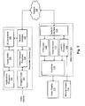
- Fig. 1 is a functional block diagram of an illustrative system comprising a residential gateway and a video client.
- Fig. 2 is a flow chart of an illustrative operation of the system of Fig. 1 .
- Fig. 3 is an illustrative screen shot of a residential gateway user interface overlaid on video content.
- Fig. 4 is an illustrative screen shot of a residential gateway user interface displayed in a picture-in-picture format.
- Fig. 5 is an illustrative screen shot of a residential gateway user interface displayed side by side with video content.
- Fig. 1 is a functional block diagram of an illustrative system in which a residential gateway 101 and a video client 103 are communicatively connected via a network 102. While a residential gateway and a video client are shown in this example, residential gateway 101 may be replaced with any type of device capable of forwarding an interactive user interface to a video client. Likewise, video client 103 may be any type of device capable of receiving and causing the interactive user interface to be displayed to a user, and potentially also allowing the user to interact with the interactive user interface. Thus, the concepts described herein are not limited to interactions between a residential gateway and a video client.
- Residential gateway 101 includes, in this example, an applications processor 104, a frame buffer 105, a user interface (UI) compressor 106, a program tuner 107, a video transport processor 108, and a network interface 109.
- Video client 103 includes, in this example, a UI decoder 110, a video decoder 111, a local UI processor 112, a combiner 113, and a network interface 114.
- Video client 103 may further include and/or otherwise be communicatively coupled to (e.g., via wire or wirelessly), a video display 115 and a remote control 116.
- UI decoder 110 and video decoder 111 may utilize physically separate decoder circuitry or may utilize the same physical decoder circuitry.
- UI decoder 110 and video decoder 111 may be separate software code or share the same or utilize overlapping software code.
- Each of residential gateway 101 and video client 103 may also include additional functional blocks not shown in Fig. 1 .
- video client 103 may be physically integrated with or separate from video display 115.
- Residential gateway 101 and video client 103 may each be implemented, for example, as a computer.
- Non-limiting examples of a computer include one or more personal computers (e.g., desktop or laptop), servers, smart phones, personal digital assistants (PDAs), television set top boxes, and/or a system of these in any combination or subcombination.
- PDAs personal digital assistants
- a given computer may be physically located completely in one location or may be distributed amongst a plurality of locations (i.e., may implement distributive computing).
- a computer may be or include a general-purpose computer and/or a dedicated computer configured to perform only certain limited functions.
- a computer typically includes hardware that may execute software to perform specific functions.
- the software if any, may be stored on a computer-readable medium in the form of computer-readable instructions.
- a computer may read those computer-readable instructions, and in response perform various steps as defined by those computer-readable instructions.
- any functions attributed to residential gateway 101 and video client 103 as described herein may be implemented, for example, by reading and executing such computer-readable instructions for performing those functions, and/or by any hardware subsystem (e.g., a processor) from which the computer is composed.
- any of the above-mentioned functions may be implemented by the hardware of the computer, with or without the execution of software.
- the computer may be or include an application-specific integrated circuit (ASIC), field-programmable gate array (FPGA), or other type of circuitry that is configured to perform some or all of the functions attributed to the computer.
- the processor may be implemented as or otherwise include the ASIC, FPGA, or other type of circuitry.
- computer-readable medium includes not only a single physical medium or single type of medium, but also a combination of one or more physical media and/or types of media. Examples of a computer-readable medium include, but are not limited to, one or more memories, hard drives, optical discs (such as CDs or DVDs), magnetic discs, and magnetic tape drives.
- Such a computer-readable medium may store computer-readable instructions (e.g., software) and/or computer-readable data (i.e., information that may or may not be executable).
- a computer-readable medium (such as memory) may be included in any one or more of blocks 104-109 and 110-114, and may store computer-executable instructions and/or data used by any of those blocks 104-109 and 110-114.
- such a computer-readable medium storing the data and/or software may be physically separate from, yet accessible by, residential gateway 101 and/or video client 103.
- Network 102 may serve to communicatively couple residential gateway 101 and video client 103 together, and may be any type of network or combination of networks. Examples of network 102 include, but are not limited to, the Internet, an intranet, a local-area network (LAN), a landline telephone network, a satellite communication network, and a cellular telephone network or other type of wireless network. In other embodiments, residential gateway 101 may be directly coupled to video client 103 without intervening network 102.
- LAN local-area network
- residential gateway 101 may be directly coupled to video client 103 without intervening network 102.
- applications processor 104 is responsible for generating data representing an interactive user interface that is intended to be viewed by the user of video client 103.
- Applications processor 104 may generate the user interface based on one or more inputs, which may include input received from video client 103 (e.g., in accordance with commands from the user via remote control 116). This responsiveness to inputs is what makes the user interface interactive.
- Applications processor 104 may be implemented as one or more physical processors (e.g., a central processing unit, or CPU) and/or other circuitry, and may operate, for example, in accordance with computer-executable instructions stored in a computer-readable medium that will be considered for this example to be part of block 104.
- the generated interactive user interface may include, for example, text and/or graphics, such as shown in element 302 of Fig. 3 .
- frame buffer 105 may be configured to receive the data representing the user interface, and for creating and/or storing one or more video frames from that data.
- the video frames at this point represent an uncompressed interactive user interface.
- UI compressor 106 may be configured to receive the video frames from frame buffer 105 and compressing the video frames to generate a compressed user interface.
- the compression may be any type of lossy or non-lossy compression, and may be of low complexity or high complexity. However, where lower latency of a highly dynamic interactive user interface is desired, it may be desirable to use a lower complexity compression algorithm.
- Non-limiting examples of compression that may be used include MPEG (e.g., MPEG-2 and MPEG-4) and VC-1.
- future as-yet-not-developed compression techniques may also be used.
- UI compressor 106 may reduce the size of the data needed to represent the interactive user interface in other ways, such as by reducing the frame rate and/or the resolution of the interactive user interface.
- UI compressor 106 may be implemented as a software and/or hardware unit, and may include, for instance, a digital signal processing chip and/or a processor such as a CPU.
- Network interface 109 is responsible for some or all communications with network 102. For example, network interface 109 sends the data from UI compressor 106 representing the compressed interactive user interface to network 102 and receives any input commands from video client 103 via network 102. Network interface 109 also sends any video programming content from video transport processor 108 to network 102. Any communications sent to and/or received from network 102 may further be buffered by network interface 109 while waiting for other functions of residential gateway 101 to be ready. Network interface 109 of residential gateway 101 and network interface 114 of video client 103 may also be responsible for negotiating a desired quality of service (QoS) with each other.
- QoS quality of service
- the buffering function of network interface 109 may be able to help provide the desired QoS by delaying transmission of the video content and/or interactive user interface over network 102 until a sufficient quantity of either is accumulated in the buffer, thereby smoothing out delays that may occur between the video source and program tuner 107.
- Program tuner 107 may be configured to receive desired video content from a video source that may or may not be external to residential gateway 101.
- the video source may be, for example, a signal received from a television content service provider.
- the video source may be a local storage medium (e.g., a hard drive or memory) storing video content, wherein the local storage medium may be part of and/or coupled to residential gateway 101.
- a local video source may be coupled to residential gateway 101 via network 102.
- program tuner 107 may receive selected video content either directly from the video source (as shown for example in Fig. 1 ) or from network 102 via network interface 109.
- Program tuner 107 may select particular video content from a plurality of different video contents depending upon the format of the video content transmission. For instance, where the video content is digitally received, then program tuner 107 may selectively receive and process only those data packets corresponding to the desired video content. Where different video contents are transmitted over different carrier frequencies, then program tuner 107 may include a frequency tuner for selectively receiving only the desired modulated carrier frequency for the desired video content.
- the video content as received may already be compressed, such as by MPEG compression.
- the interactive user interface may be compressed by UI compressor 106 using the same compression as the video content, or using a different compression as the video content. For instance, the video content may be compressed using non-lossy compression, and the interactive user interface may be compressed using lossy compression, or vice-versa. Also, any compression used may be a low-latency type of compression, as desired.
- Video transport processor 108 may be configured to adapt the video content to be consistent with network-specific protocols, such as but not limited to transport stream requirements, Real-Time Transport Protocol (RTP), Transmission Control Protocol (TCP), and/or multicasting protocols.
- network-specific protocols such as but not limited to transport stream requirements, Real-Time Transport Protocol (RTP), Transmission Control Protocol (TCP), and/or multicasting protocols.
- network interface 114 may be responsible for all communications with network 102. For example, video programming and the compressed interactive user interface from residential gateway 101 may be received by network interface 114. Also, any commands issued by video client 103 (e.g., initiated by a command from remote control 116) may also be sent to residential gateway 101 via network 102 using network interface 114.
- UI decoder 110 may be responsible for decompressing the compressed interactive user interface received from network interface 114.
- the decompression may be of a type that reverses the compression used by UI compressor 106.
- UI decoder 110 may use an MPEG-2 decoder to decompress the interactive user interface.
- UI decoder 110 may be implemented as a software and/or hardware unit, and may include, for instance, a digital signal processing chip and/or a processor such as a CPU.
- Video decoder 111 may be responsible for decompressing the video content received from network interface 114 (assuming that the video content has been compressed). The decompression may be of a type that reverses the compression by which the video content was previously compressed. For example, if the interactive user interface was compressed using MPEG-2, then video decoder 111 may use an MPEG-2 decoder to decompress the interactive user interface. Video decoder 111 may be implemented as a software and/or hardware unit, and may include, for instance, a digital signal processing chip and/or a processor such as a CPU.
- video client 103 supports picture-in-picture (PiP), picture-in-graphics (PiG), and/or graphics-in-picture (GiP) functionality
- a video client 103 may include dedicated PiP, PiG, and/or GiP decoding circuitry.
- video decoder 111 may be implemented as, or otherwise include, the PiP/PiG/GiP decoding circuitry.
- video decoder 111 and UI decoder 110 may share the same physical decoder circuitry and/or software, and/or may utilize separate decoder circuitry and/or separate software.
- video decoder 111 may utilize the PiP/PiG/GiP decoding circuitry and UI decoder 110 may utilize separate decoding circuitry conventionally used for video decoding.
- Local UI processor 112 may be responsible for determining how the decompressed interactive user interface and/or the decompressed video content is to be displayed on video display 115. For example, local UI processor 112 may determine that the interactive user interface is to be displayed overlaid on top of the video content (as shown by way of example in Fig. 3 ). Or, local UI processor 112 may determine that the interactive user interface is to be displayed as a PiP, PiG, or GiP window over the video content (as shown by way of example in Fig. 4 ). Or, local UI processor 112 may determine that the interactive user interface and the video content are to be displayed in different non-overlapping regions of the video frame (as shown by way of example in Fig. 5 ). The way that local UI processor 112 determines that the interactive user interface and the video content are displayed relative to each other may depend upon, for example, user input, such as via remote control 116, and/or upon a command received via network 102 from residential gateway 101.
- Combiner 113 may combine the interactive user interface and the video content into a single video frame signal to be displayed on video display 115 in the manner determined by local UI processor 112. To allow the interactive user interface to be overlaid on top of the video content with or without transparency, combiner 113 may include an alpha blender, for example. In some embodiments, combiner 113 may include or otherwise be implemented as a compositor that combines the video image of the interactive user interface and the video image of the video content.
- Fig. 2 is a flow chart of an illustrative operation of the system of Fig. 1 .
- Steps 201-203 are performed in this example by residential gateway 101
- steps 204-209 are performed in this example by video client 103. While the various steps are shown sequentially by way of example, this is merely for simplicity of explanation; some of the steps may be performed simultaneously and/or continuously along with others of the steps. Also, the steps performed by residential gateway 101 may be performed simultaneously with the steps performed by video client 103.
- the interactive user interface may be generated by applications processor 104 in the manner discussed previously, for example. While the interactive user interface is being generated, and/or afterward, frame buffer 105 may buffer and organize the video frames of the interactive user interface and feed them to UI compressor 106. In step 202, UI compressor 106 compresses the interactive user interface.
- the video content as well as the compressed interactive user interface are received by network interface 109 from program tuner 107 via video transports processor 108, and are sent out over network 102 by network interface 109, for example.
- the compressed interactive user interface and the video content may be sent separately, even though they may be sent simultaneously. For example, they may be sent as separate data streams each with its own stream identifier in the associated data packets.
- the compressed interactive user interface data and the video content data may be sent over network 102 in a time-sliced (multiplexed) manner.
- step 204 the video content and compressed interactive user interface are received from network 102 by network interface 114, and the video content and compressed interactive user interface data may be separated from each other, if needed and depending upon the format in which the video content and compressed interactive user interface are sent. This separation may be performed by network interface 114, video decoder 111, and/or UI decoder 110. Where the video content and compressed interactive user interface data were sent over network 102 in a time-sliced (multiplexed) manner, separation may involve de-multiplexing.
- steps 205 and 206 the video content is decompressed by video decoder 111 (if the video content was compressed) and the compressed interactive user interface is decompressed by UI decoder 110, for example.
- UI decoder 110 and video decoder 111 may alternate usage of those resources so that the video content and the interactive user interface are effectively decompressed simultaneously.
- step 207 local UI processor 112 and combiner 113 combine the decompressed video content and decompressed interactive user interface into one or more video frames.
- a combination may include overlaying of the interactive user interface onto (e.g., at least partially overlapping) the video content.
- FIG. 3 shows that video content 301 is displayed simultaneously with interactive user interface 302 overlaid onto (e.g., alpha blended with) underlying video content 301.
- the location of interactive user interface 302 is shown by way of example near the bottom of the video frame, however, interactive user interface 302 could be located anywhere in the video frame and at any size.
- combining may include displaying the interactive user interface in a picture-in-picture layout simultaneously with, and inside or at least partially overlapping, the video content.
- FIG. 4 shows that interactive user interface 302 is displayed in a PiP window 401 (which alternatively could be a PiG or GiP window).
- the location of PiP window 401 is shown in the lower left quadrant of the video frame, however PiP window 401 could be located anywhere in the video frame, and it could be of any size.
- combining may include simultaneously displaying interactive user interface 302 and the video content in different non-overlapping regions of the video frame (e.g., side by side). This is shown by way of example in Fig. 5 .
- interactive user interface 302 is displayed adjacent the video content 301.
- they could be displayed in any relative configuration, such as one toward the top of the video frame and the other toward the bottom of the video frame.
- interactive user interface 302 and video content 301 may be displayed at any sizes relative to each other.
- simultaneous display of both the interactive user interface and the video content has been referred to herein. It is to be understood that such simultaneous display includes not only the case where every video frame in a video frame sequence includes both the interactive user interface and the video content, but also the case where they are interleaved so as to provide what appears to be simultaneity to the human eye.
- video frames might be interleaved to include either the video content or the interactive user interface in an alternating manner. In such a situation using a typical video display frame rate, a human eye could not tell that they are alternating frames, and it would rather appear that the video content and the interactive user interface are being displayed simultaneously.
- the type and configuration of the combining may be user-selectable (e.g., via remote control 116). Because the interactive user interface is transmitted to video client 103 separately from the video content, and because the interactive user interface and the video content may each be sent as its own complete video frame, video client 103 may be free to combine these in the video frame in any manner desired, including changing the relative sizes and positions of the interactive user interface and the video content within the resulting combined video frame as displayed at video display 115.
- Video display 115 may be implemented as, for instance, a cathode ray tube (CRT) monitor, a liquid crystal display (LCD) monitor, a plasma display, a wireless handheld or other portable device, a television set, or any other type of device capable of presenting a dynamic visual image to a user.
- CTR cathode ray tube
- LCD liquid crystal display
- plasma display a plasma display
- wireless handheld or other portable device a wireless handheld or other portable device
- television set or any other type of device capable of presenting a dynamic visual image to a user.
- any commands initiated by the user may be sent to residential gateway 101 over network 102, using network interface 114.
- These commands may include, for instance, commands interacting with the interactive user interface such as by moving through a menu presented by the interactive user interface and/or selecting an item from the menu.
- These commands may also include commands that may not necessarily be directly related to the interactive user interface.
- user-initiated commands may be executed locally by video client 103, rather than being sent back to residential gateway 101. For example, a command may be issued by the user, e.g., via remote control 116, to switch between combining modes.
- step 209 may occur at any time during the process performed by video client 103.
- each of residential gateway 101 and video client 103 may cycle through their respective processes continuously. For instance, each may perform one or more cycles per video frame.
Abstract
Description
- Remote user interfaces are commonly used by a first device to interact with a second device. The remote user interface is typically generated by the second device and sent to the first device to be presented to the user. Such remote user interface implementations generally fall into two categories: protocol-specific and remote terminal.
- Protocol-specific remote user interfaces may be highly optimized for a specific application, network, and client architecture. While protocol-specific remote user interfaces can be bandwidth efficient and can support dynamic user interfaces as a practical matter, they are typically limited to servicing very specific client devices rather than standardized client devices.
- Remote terminal user interfaces typically transfer the entire video frame buffer from the second device to the first device for remote rendering. Compared with the protocol-specific remote user interface, this type of remote interface uses a lower complexity mechanism and is more flexible as to client device type. However, remote terminal interfaces have thus far been generally limited as a practical matter to static displays, due to the relatively high bandwidth needed to send the video frames of dynamic user interfaces.
- Aspects as described herein are directed to making interactive user interfaces such as remote terminal user interfaces more bandwidth efficient. For example, the interactive user interface may include video that is compressed prior to transmission to the video client. Such compression may reduce the amount of bandwidth needed to transmit the interactive user interface, thereby potentially allowing the interactive user interface to be more detailed and/or more dynamic, even to the point of being pixel-accurate from generation to viewing.
- According to some aspects, the compression may be performed independently of any other video that may be simultaneously transmitted to the video client. At the client side, these two compressed video streams (remote user interface and video content) may be decompressed independently of each other. In some cases, technology already existing in some client devices, such as picture-in-picture (PiP) capability, may be leveraged to decompress the received compressed remote user interface without needing to modify the hardware of those client devices.
- In addition, because positioning and scaling of the displayed interactive user interface may be performed by the video client rather than the device generating the interactive user interface (e.g., a residential gateway or television content provider), this may potentially reduce the workload of the residential gateway or provider's system. For instance, the residential gateway or provider's system may no longer need to send different customized versions of the interactive user interface to different viewing client devices depending upon the client device capabilities.
- Therefore, some aspects are directed to an apparatus, system, software, and method that may involve or perform the following: receiving first data representing compressed video content, receiving second data representing a compressed interactive user interface, decompressing the compressed video content, decompressing the compressed interactive user interface separately from the compressed video content, and generating a video signal that includes both the decompressed video content and the decompressed interactive user interface.
- Still further aspects are directed to an apparatus, comprising a network interface configured to receive from a network first data representing a compressed interactive user interface and second data representing video content, a decoder configured to decompress the compressed interactive user interface and to decompress the compressed video content, and a combiner configured to generate a video signal combining the decompressed interactive user interface with the decompressed video content.
- Still further aspects are directed to an apparatus, system, software, and method that may involve or perform the following: receiving first data representing video content, generating second data representing an interactive user interface, compressing the interactive user interface, and sending third data representing the video content and fourth data representing the compressed interactive user interface
- Yet further aspects are directed to an apparatus, comprising a program tuner configured to receive first data representing video content, a processor configured to generate second data representing an interactive user interface, a compressor configured to compress the interactive user interface, and a network interface configured to send third data representing the video content and fourth data representing the compressed interactive user interface.
- These and other aspects of the disclosure will be apparent upon consideration of the following detailed description.
- A more complete understanding of the present disclosure and the potential advantages of various aspects described herein may be acquired by referring to the following description in consideration of the accompanying drawings, in which like reference numbers indicate like features, and wherein:
-
Fig. 1 is a functional block diagram of an illustrative system comprising a residential gateway and a video client. -
Fig. 2 is a flow chart of an illustrative operation of the system ofFig. 1 . -
Fig. 3 is an illustrative screen shot of a residential gateway user interface overlaid on video content. -
Fig. 4 is an illustrative screen shot of a residential gateway user interface displayed in a picture-in-picture format. -
Fig. 5 is an illustrative screen shot of a residential gateway user interface displayed side by side with video content. -
Fig. 1 is a functional block diagram of an illustrative system in which aresidential gateway 101 and avideo client 103 are communicatively connected via anetwork 102. While a residential gateway and a video client are shown in this example,residential gateway 101 may be replaced with any type of device capable of forwarding an interactive user interface to a video client. Likewise,video client 103 may be any type of device capable of receiving and causing the interactive user interface to be displayed to a user, and potentially also allowing the user to interact with the interactive user interface. Thus, the concepts described herein are not limited to interactions between a residential gateway and a video client. -
Residential gateway 101 includes, in this example, anapplications processor 104, aframe buffer 105, a user interface (UI)compressor 106, aprogram tuner 107, avideo transport processor 108, and anetwork interface 109.Video client 103 includes, in this example, aUI decoder 110, avideo decoder 111, alocal UI processor 112, acombiner 113, and anetwork interface 114.Video client 103 may further include and/or otherwise be communicatively coupled to (e.g., via wire or wirelessly), avideo display 115 and aremote control 116. - While various separate functional blocks are shown in
Fig. 1 , two or more of these functional blocks may or may not be physically combined together into a single physical unit. Moreover, one or more of these functional blocks may be sub-divided into multiple physical units. In other words, the functional block division as shown inFig. 1 may either correspond to or be independent of the physical implementation of the functional blocks. For example,UI decoder 110 andvideo decoder 111 may utilize physically separate decoder circuitry or may utilize the same physical decoder circuitry. Or,UI decoder 110 andvideo decoder 111 may be separate software code or share the same or utilize overlapping software code. Each ofresidential gateway 101 andvideo client 103 may also include additional functional blocks not shown inFig. 1 . As another example,video client 103 may be physically integrated with or separate fromvideo display 115. -
Residential gateway 101 andvideo client 103 may each be implemented, for example, as a computer. The term "computer" as referred to herein broadly refers to any electronic, electro-optical, and/or mechanical device, or system of multiple physically separate such devices, that is able to process and manipulate information, such as in the form of data. Non-limiting examples of a computer include one or more personal computers (e.g., desktop or laptop), servers, smart phones, personal digital assistants (PDAs), television set top boxes, and/or a system of these in any combination or subcombination. In addition, a given computer may be physically located completely in one location or may be distributed amongst a plurality of locations (i.e., may implement distributive computing). A computer may be or include a general-purpose computer and/or a dedicated computer configured to perform only certain limited functions. - A computer typically includes hardware that may execute software to perform specific functions. The software, if any, may be stored on a computer-readable medium in the form of computer-readable instructions. A computer may read those computer-readable instructions, and in response perform various steps as defined by those computer-readable instructions. Thus, any functions attributed to
residential gateway 101 andvideo client 103 as described herein may be implemented, for example, by reading and executing such computer-readable instructions for performing those functions, and/or by any hardware subsystem (e.g., a processor) from which the computer is composed. Additionally or alternatively, any of the above-mentioned functions may be implemented by the hardware of the computer, with or without the execution of software. For example, the computer may be or include an application-specific integrated circuit (ASIC), field-programmable gate array (FPGA), or other type of circuitry that is configured to perform some or all of the functions attributed to the computer. In such embodiments, the processor may be implemented as or otherwise include the ASIC, FPGA, or other type of circuitry. - The term "computer-readable medium" as used herein includes not only a single physical medium or single type of medium, but also a combination of one or more physical media and/or types of media. Examples of a computer-readable medium include, but are not limited to, one or more memories, hard drives, optical discs (such as CDs or DVDs), magnetic discs, and magnetic tape drives.
- Such a computer-readable medium may store computer-readable instructions (e.g., software) and/or computer-readable data (i.e., information that may or may not be executable). In the present example, a computer-readable medium (such as memory) may be included in any one or more of blocks 104-109 and 110-114, and may store computer-executable instructions and/or data used by any of those blocks 104-109 and 110-114. Alternatively or additionally, such a computer-readable medium storing the data and/or software may be physically separate from, yet accessible by,
residential gateway 101 and/orvideo client 103. - Network 102 may serve to communicatively couple
residential gateway 101 andvideo client 103 together, and may be any type of network or combination of networks. Examples ofnetwork 102 include, but are not limited to, the Internet, an intranet, a local-area network (LAN), a landline telephone network, a satellite communication network, and a cellular telephone network or other type of wireless network. In other embodiments,residential gateway 101 may be directly coupled tovideo client 103 without interveningnetwork 102. - Turning to the functional blocks of
residential gateway 101 shown in the example ofFig. 1 ,applications processor 104 is responsible for generating data representing an interactive user interface that is intended to be viewed by the user ofvideo client 103.Applications processor 104 may generate the user interface based on one or more inputs, which may include input received from video client 103 (e.g., in accordance with commands from the user via remote control 116). This responsiveness to inputs is what makes the user interface interactive.Applications processor 104 may be implemented as one or more physical processors (e.g., a central processing unit, or CPU) and/or other circuitry, and may operate, for example, in accordance with computer-executable instructions stored in a computer-readable medium that will be considered for this example to be part ofblock 104. However, as discussed above, it is possible thatapplications processor 104 may operate solely on a hardware basis without the need for executing computer-executable instructions. The generated interactive user interface may include, for example, text and/or graphics, such as shown inelement 302 ofFig. 3 . - In this example,
frame buffer 105 may be configured to receive the data representing the user interface, and for creating and/or storing one or more video frames from that data. Thus, the video frames at this point represent an uncompressed interactive user interface. -
UI compressor 106 may be configured to receive the video frames fromframe buffer 105 and compressing the video frames to generate a compressed user interface. The compression may be any type of lossy or non-lossy compression, and may be of low complexity or high complexity. However, where lower latency of a highly dynamic interactive user interface is desired, it may be desirable to use a lower complexity compression algorithm. Non-limiting examples of compression that may be used include MPEG (e.g., MPEG-2 and MPEG-4) and VC-1. In addition to existing compression techniques, future as-yet-not-developed compression techniques may also be used. In addition to the above-mentioned compression,UI compressor 106 may reduce the size of the data needed to represent the interactive user interface in other ways, such as by reducing the frame rate and/or the resolution of the interactive user interface. - Regardless of how compression is performed, the data representing the interactive user interface output by
UI compressor 106 is compressed relative to the data representing the interactive user interface as received fromframe buffer 105.UI compressor 106 may be implemented as a software and/or hardware unit, and may include, for instance, a digital signal processing chip and/or a processor such as a CPU. -
Network interface 109 is responsible for some or all communications withnetwork 102. For example,network interface 109 sends the data fromUI compressor 106 representing the compressed interactive user interface to network 102 and receives any input commands fromvideo client 103 vianetwork 102.Network interface 109 also sends any video programming content fromvideo transport processor 108 tonetwork 102. Any communications sent to and/or received fromnetwork 102 may further be buffered bynetwork interface 109 while waiting for other functions ofresidential gateway 101 to be ready.Network interface 109 ofresidential gateway 101 andnetwork interface 114 ofvideo client 103 may also be responsible for negotiating a desired quality of service (QoS) with each other. In addition, the buffering function ofnetwork interface 109 may be able to help provide the desired QoS by delaying transmission of the video content and/or interactive user interface overnetwork 102 until a sufficient quantity of either is accumulated in the buffer, thereby smoothing out delays that may occur between the video source andprogram tuner 107. -
Program tuner 107 may be configured to receive desired video content from a video source that may or may not be external toresidential gateway 101. The video source may be, for example, a signal received from a television content service provider. In another example, the video source may be a local storage medium (e.g., a hard drive or memory) storing video content, wherein the local storage medium may be part of and/or coupled toresidential gateway 101. In fact, such a local video source may be coupled toresidential gateway 101 vianetwork 102. Accordingly,program tuner 107 may receive selected video content either directly from the video source (as shown for example inFig. 1 ) or fromnetwork 102 vianetwork interface 109. -
Program tuner 107 may select particular video content from a plurality of different video contents depending upon the format of the video content transmission. For instance, where the video content is digitally received, thenprogram tuner 107 may selectively receive and process only those data packets corresponding to the desired video content. Where different video contents are transmitted over different carrier frequencies, thenprogram tuner 107 may include a frequency tuner for selectively receiving only the desired modulated carrier frequency for the desired video content. The video content as received may already be compressed, such as by MPEG compression. And, where the video content is compressed, the interactive user interface may be compressed byUI compressor 106 using the same compression as the video content, or using a different compression as the video content. For instance, the video content may be compressed using non-lossy compression, and the interactive user interface may be compressed using lossy compression, or vice-versa. Also, any compression used may be a low-latency type of compression, as desired. -
Video transport processor 108 may be configured to adapt the video content to be consistent with network-specific protocols, such as but not limited to transport stream requirements, Real-Time Transport Protocol (RTP), Transmission Control Protocol (TCP), and/or multicasting protocols. - Turning to the functional blocks of
video client 103 shown in the example ofFig. 1 ,network interface 114 may be responsible for all communications withnetwork 102. For example, video programming and the compressed interactive user interface fromresidential gateway 101 may be received bynetwork interface 114. Also, any commands issued by video client 103 (e.g., initiated by a command from remote control 116) may also be sent toresidential gateway 101 vianetwork 102 usingnetwork interface 114. -
UI decoder 110 may be responsible for decompressing the compressed interactive user interface received fromnetwork interface 114. The decompression may be of a type that reverses the compression used byUI compressor 106. For example, if the interactive user interface is compressed using MPEG-2, thenUI decoder 110 may use an MPEG-2 decoder to decompress the interactive user interface.UI decoder 110 may be implemented as a software and/or hardware unit, and may include, for instance, a digital signal processing chip and/or a processor such as a CPU. -
Video decoder 111 may be responsible for decompressing the video content received from network interface 114 (assuming that the video content has been compressed). The decompression may be of a type that reverses the compression by which the video content was previously compressed. For example, if the interactive user interface was compressed using MPEG-2, thenvideo decoder 111 may use an MPEG-2 decoder to decompress the interactive user interface.Video decoder 111 may be implemented as a software and/or hardware unit, and may include, for instance, a digital signal processing chip and/or a processor such as a CPU. Wherevideo client 103 supports picture-in-picture (PiP), picture-in-graphics (PiG), and/or graphics-in-picture (GiP) functionality, then avideo client 103 may include dedicated PiP, PiG, and/or GiP decoding circuitry. In that case,video decoder 111 may be implemented as, or otherwise include, the PiP/PiG/GiP decoding circuitry. Also,video decoder 111 andUI decoder 110 may share the same physical decoder circuitry and/or software, and/or may utilize separate decoder circuitry and/or separate software. For example, wherevideo client 103 supports PiP/PiG/GiP functionality,video decoder 111 may utilize the PiP/PiG/GiP decoding circuitry andUI decoder 110 may utilize separate decoding circuitry conventionally used for video decoding. -
Local UI processor 112 may be responsible for determining how the decompressed interactive user interface and/or the decompressed video content is to be displayed onvideo display 115. For example,local UI processor 112 may determine that the interactive user interface is to be displayed overlaid on top of the video content (as shown by way of example inFig. 3 ). Or,local UI processor 112 may determine that the interactive user interface is to be displayed as a PiP, PiG, or GiP window over the video content (as shown by way of example inFig. 4 ). Or,local UI processor 112 may determine that the interactive user interface and the video content are to be displayed in different non-overlapping regions of the video frame (as shown by way of example inFig. 5 ). The way thatlocal UI processor 112 determines that the interactive user interface and the video content are displayed relative to each other may depend upon, for example, user input, such as viaremote control 116, and/or upon a command received vianetwork 102 fromresidential gateway 101. -
Combiner 113 may combine the interactive user interface and the video content into a single video frame signal to be displayed onvideo display 115 in the manner determined bylocal UI processor 112. To allow the interactive user interface to be overlaid on top of the video content with or without transparency,combiner 113 may include an alpha blender, for example. In some embodiments,combiner 113 may include or otherwise be implemented as a compositor that combines the video image of the interactive user interface and the video image of the video content. -
Fig. 2 is a flow chart of an illustrative operation of the system ofFig. 1 . Steps 201-203 are performed in this example byresidential gateway 101, and steps 204-209 are performed in this example byvideo client 103. While the various steps are shown sequentially by way of example, this is merely for simplicity of explanation; some of the steps may be performed simultaneously and/or continuously along with others of the steps. Also, the steps performed byresidential gateway 101 may be performed simultaneously with the steps performed byvideo client 103. - In
step 201, the interactive user interface may be generated byapplications processor 104 in the manner discussed previously, for example. While the interactive user interface is being generated, and/or afterward,frame buffer 105 may buffer and organize the video frames of the interactive user interface and feed them toUI compressor 106. In step 202,UI compressor 106 compresses the interactive user interface. - In
step 203, the video content as well as the compressed interactive user interface are received bynetwork interface 109 fromprogram tuner 107 via video transportsprocessor 108, and are sent out overnetwork 102 bynetwork interface 109, for example. The compressed interactive user interface and the video content may be sent separately, even though they may be sent simultaneously. For example, they may be sent as separate data streams each with its own stream identifier in the associated data packets. As another example, the compressed interactive user interface data and the video content data may be sent overnetwork 102 in a time-sliced (multiplexed) manner. - In
step 204, the video content and compressed interactive user interface are received fromnetwork 102 bynetwork interface 114, and the video content and compressed interactive user interface data may be separated from each other, if needed and depending upon the format in which the video content and compressed interactive user interface are sent. This separation may be performed bynetwork interface 114,video decoder 111, and/orUI decoder 110. Where the video content and compressed interactive user interface data were sent overnetwork 102 in a time-sliced (multiplexed) manner, separation may involve de-multiplexing. Insteps 205 and 206, the video content is decompressed by video decoder 111 (if the video content was compressed) and the compressed interactive user interface is decompressed byUI decoder 110, for example. It may be expected that video content decompression and interactive user interface decompression will occur simultaneously, especially whereUI decoder 110 andvideo decoder 111 do not share resources. However, where UI andvideo decoders UI decoder 110 andvideo decoder 111 may alternate usage of those resources so that the video content and the interactive user interface are effectively decompressed simultaneously. - In
step 207,local UI processor 112 andcombiner 113 combine the decompressed video content and decompressed interactive user interface into one or more video frames. As previously mentioned, such a combination may include overlaying of the interactive user interface onto (e.g., at least partially overlapping) the video content. This is shown by way of example inFig. 3 , in whichvideo content 301 is displayed simultaneously withinteractive user interface 302 overlaid onto (e.g., alpha blended with) underlyingvideo content 301. The location ofinteractive user interface 302 is shown by way of example near the bottom of the video frame, however,interactive user interface 302 could be located anywhere in the video frame and at any size. - Alternatively, combining may include displaying the interactive user interface in a picture-in-picture layout simultaneously with, and inside or at least partially overlapping, the video content. This is shown by way of example in
Fig. 4 , in whichinteractive user interface 302 is displayed in a PiP window 401 (which alternatively could be a PiG or GiP window). The location ofPiP window 401 is shown in the lower left quadrant of the video frame, howeverPiP window 401 could be located anywhere in the video frame, and it could be of any size. - As another possibility, combining may include simultaneously displaying
interactive user interface 302 and the video content in different non-overlapping regions of the video frame (e.g., side by side). This is shown by way of example inFig. 5 . In this example,interactive user interface 302 is displayed adjacent thevideo content 301. However, they could be displayed in any relative configuration, such as one toward the top of the video frame and the other toward the bottom of the video frame. Also,interactive user interface 302 andvideo content 301 may be displayed at any sizes relative to each other. - The simultaneous display of both the interactive user interface and the video content has been referred to herein. It is to be understood that such simultaneous display includes not only the case where every video frame in a video frame sequence includes both the interactive user interface and the video content, but also the case where they are interleaved so as to provide what appears to be simultaneity to the human eye. For example, video frames might be interleaved to include either the video content or the interactive user interface in an alternating manner. In such a situation using a typical video display frame rate, a human eye could not tell that they are alternating frames, and it would rather appear that the video content and the interactive user interface are being displayed simultaneously.
- Moreover, the type and configuration of the combining may be user-selectable (e.g., via remote control 116). Because the interactive user interface is transmitted to
video client 103 separately from the video content, and because the interactive user interface and the video content may each be sent as its own complete video frame,video client 103 may be free to combine these in the video frame in any manner desired, including changing the relative sizes and positions of the interactive user interface and the video content within the resulting combined video frame as displayed atvideo display 115. - Returning to
Fig. 2 , in step 208 the resulting video frames output fromcombiner 113 are then provided tovideo display 115 for display to the user.Video display 115 may be implemented as, for instance, a cathode ray tube (CRT) monitor, a liquid crystal display (LCD) monitor, a plasma display, a wireless handheld or other portable device, a television set, or any other type of device capable of presenting a dynamic visual image to a user. - In
step 209, any commands initiated by the user (e.g., using remote control 116) and/or initiated byvideo client 103 may be sent toresidential gateway 101 overnetwork 102, usingnetwork interface 114. These commands may include, for instance, commands interacting with the interactive user interface such as by moving through a menu presented by the interactive user interface and/or selecting an item from the menu. These commands may also include commands that may not necessarily be directly related to the interactive user interface. In addition, user-initiated commands may be executed locally byvideo client 103, rather than being sent back toresidential gateway 101. For example, a command may be issued by the user, e.g., viaremote control 116, to switch between combining modes. Examples of such locally-executed commands may include a command to switch between combining modes and/or a command to indicate where on the video frame the interactive user interface and/or the video content should be located relative to each other. Althoughstep 209 is shown occurring after step 208,step 209 may occur at any time during the process performed byvideo client 103. - As shown in
Fig. 2 , each ofresidential gateway 101 andvideo client 103 may cycle through their respective processes continuously. For instance, each may perform one or more cycles per video frame. - Thus, techniques have been described for potentially making interactive user interfaces such as remote terminal user interfaces more bandwidth efficient. Although examples have been discussed in connection with an interactive user interface generated by a residential gateway and viewed by a video client, such interactions may be implemented between any two devices. For instance, a television content service provider component location, such as but not limited to a headend, may generate and compress the interactive user interface, rather than a residential gateway. And while examples have been described in connection with a video client that may be, for instance, a home television set top box, the video client may be other types of video-capable devices such as smart phones or other handheld computers.
Claims (15)
- A method, comprising:receiving first data representing compressed video content;receiving second data representing a compressed interactive user interface;decompressing the compressed video content;decompressing the compressed interactive user interface separately from the compressed video content; andgenerating a video signal that includes both the decompressed video content and the decompressed interactive user interface.
- The method of claim 1, wherein generating comprises generating the video signal such that the decompressed interactive user interface is displayed simultaneously with the decompressed video content.
- The method of claim 1 or claim 2, wherein generating comprises generating a first plurality of video frames interleaved with a second plurality of video frames, wherein the first plurality of video frames comprises the decompressed interactive user interface but not the decompressed video content, and the second plurality of video frames comprises the decompressed video content but not the decompressed interactive user interface.
- The method of any preceding claim, wherein the compressed video content is compressed using non-lossy compression and the compressed interactive user interface is compressed using lossy compression.
- The method of any preceding claim, further comprising receiving user input, wherein generating comprises generating the video signal such that a location of the decompressed interactive user interface in a video frame is based upon the user input.
- The method of claim 5, wherein the location is not represented by either of the received first and second data.
- An apparatus, comprising:a network interface configured to receive from a network first data representing a compressed interactive user interface and second data representing compressed video content;a decoder configured to decompress the compressed interactive user interface and to decompress the compressed video content; anda combiner configured to generate a video signal combining the decompressed interactive user interface with the decompressed video content.
- The apparatus of claim 7, wherein the decoder comprises:a first decoder configured to decompress the compressed interactive user interface; anda second decoder configured to decompress the video content.
- The apparatus of claim 7 or claim 8, wherein the combiner is configured to generate the video signal such that the decompressed interactive user interface is displayed simultaneously with the decompressed video content.
- The apparatus of any of claims 7 to 9, wherein the combiner is configured to generate a first plurality of video frames interleaved with a second plurality of video frames, wherein the first plurality of video frames comprises the decompressed interactive user interface but not the decompressed video content, and the second plurality of video frames comprises the decompressed video content but not the decompressed interactive user interface.
- The apparatus of any of claims 7 to 10, wherein the compressed video content is compressed using non-lossy compression and the compressed interactive user interface is compressed using lossy compression.
- The apparatus of any of claims 7 to 11, wherein the apparatus is further configured to receive a user input, and wherein the combiner is configured to generate the video signal such that a location of the decompressed interactive user interface in a video frame is based upon the user input.
- A method, comprising:receiving first data representing video content;generating second data representing an interactive user interface;compressing the interactive user interface; andsending third data representing the video content and fourth data representing the compressed interactive user interface.
- The method of claim 13, wherein sending comprises sending the third and fourth data to a network, wherein the method further comprises receiving fifth data from the network, and wherein generating comprises generating the second data such that the interactive user interface depends on the fifth data.
- An apparatus, comprising:a program tuner configured to receive first data representing video content;a processor configured to generate second data representing an interactive user interface;a compressor configured to compress the interactive user interface; anda network interface configured to send third data representing the video content and fourth data representing the compressed interactive user interface.
Applications Claiming Priority (1)
| Application Number | Priority Date | Filing Date | Title |
|---|---|---|---|
| US12/767,870 US11606615B2 (en) | 2010-04-27 | 2010-04-27 | Remote user interface |
Publications (2)
| Publication Number | Publication Date |
|---|---|
| EP2383986A2 true EP2383986A2 (en) | 2011-11-02 |
| EP2383986A3 EP2383986A3 (en) | 2012-05-09 |
Family
ID=44508676
Family Applications (1)
| Application Number | Title | Priority Date | Filing Date |
|---|---|---|---|
| EP20110163518 Ceased EP2383986A3 (en) | 2010-04-27 | 2011-04-21 | Remote user interface |
Country Status (3)
| Country | Link |
|---|---|
| US (2) | US11606615B2 (en) |
| EP (1) | EP2383986A3 (en) |
| CA (1) | CA2737842C (en) |
Cited By (1)
| Publication number | Priority date | Publication date | Assignee | Title |
|---|---|---|---|---|
| WO2014026135A1 (en) | 2012-08-09 | 2014-02-13 | Charter Communications Operating, Llc | System and method bridging cloud based user interfaces |
Families Citing this family (8)
| Publication number | Priority date | Publication date | Assignee | Title |
|---|---|---|---|---|
| US9826197B2 (en) | 2007-01-12 | 2017-11-21 | Activevideo Networks, Inc. | Providing television broadcasts over a managed network and interactive content over an unmanaged network to a client device |
| EP2815582B1 (en) | 2012-01-09 | 2019-09-04 | ActiveVideo Networks, Inc. | Rendering of an interactive lean-backward user interface on a television |
| US9800945B2 (en) | 2012-04-03 | 2017-10-24 | Activevideo Networks, Inc. | Class-based intelligent multiplexing over unmanaged networks |
| US10275128B2 (en) | 2013-03-15 | 2019-04-30 | Activevideo Networks, Inc. | Multiple-mode system and method for providing user selectable video content |
| US9326047B2 (en) | 2013-06-06 | 2016-04-26 | Activevideo Networks, Inc. | Overlay rendering of user interface onto source video |
| CN106464965B (en) | 2014-02-28 | 2020-02-14 | 三星电子株式会社 | Method and apparatus for displaying application data in wireless communication system |
| US9788029B2 (en) | 2014-04-25 | 2017-10-10 | Activevideo Networks, Inc. | Intelligent multiplexing using class-based, multi-dimensioned decision logic for managed networks |
| US10219014B2 (en) | 2016-06-02 | 2019-02-26 | Biamp Systems, LLC | Systems and methods for bandwidth-limited video transport |
Family Cites Families (47)
| Publication number | Priority date | Publication date | Assignee | Title |
|---|---|---|---|---|
| US5526034A (en) * | 1990-09-28 | 1996-06-11 | Ictv, Inc. | Interactive home information system with signal assignment |
| US5442700A (en) * | 1990-09-28 | 1995-08-15 | Ictv, Inc. | Scrambling method |
| DE4222110C2 (en) * | 1992-07-06 | 1998-08-27 | Nsm Ag | Program-controlled entertainment and play equipment |
| US5412708A (en) * | 1993-03-12 | 1995-05-02 | Katz; Ronald A. | Videophone system for scrutiny monitoring with computer control |
| US5495284A (en) * | 1993-03-12 | 1996-02-27 | Katz; Ronald A. | Scheduling and processing system for telephone video communication |
| US5475615A (en) * | 1993-12-23 | 1995-12-12 | U S West Advanced Technologies, Inc. | Method and system for sizing interactive video delivery systems |
| US5448568A (en) * | 1994-04-28 | 1995-09-05 | Thomson Consumer Electronics, Inc. | System of transmitting an interactive TV signal |
| US5502504A (en) * | 1994-04-28 | 1996-03-26 | Prevue Networks, Inc. | Video mix program guide |
| US5523796A (en) * | 1994-05-20 | 1996-06-04 | Prevue Networks, Inc. | Video clip program guide |
| US5828421A (en) * | 1994-10-11 | 1998-10-27 | Hitachi America, Ltd. | Implementation efficient digital picture-in-picture decoding methods and apparatus |
| DE69607528T2 (en) * | 1995-02-02 | 2000-10-19 | Koninkl Philips Electronics Nv | MIXING A VIDEO MOSAIC WITH TELETEXT |
| US5696906A (en) * | 1995-03-09 | 1997-12-09 | Continental Cablevision, Inc. | Telecommunicaion user account management system and method |
| US5850352A (en) * | 1995-03-31 | 1998-12-15 | The Regents Of The University Of California | Immersive video, including video hypermosaicing to generate from multiple video views of a scene a three-dimensional video mosaic from which diverse virtual video scene images are synthesized, including panoramic, scene interactive and stereoscopic images |
| US5818438A (en) * | 1995-04-25 | 1998-10-06 | Bellsouth Corporation | System and method for providing television services |
| US5940738A (en) * | 1995-05-26 | 1999-08-17 | Hyundai Electronics America, Inc. | Video pedestal network |
| US5793410A (en) * | 1995-05-26 | 1998-08-11 | Hyundai Electronics America | Video pedestal network |
| US6044396A (en) * | 1995-12-14 | 2000-03-28 | Time Warner Cable, A Division Of Time Warner Entertainment Company, L.P. | Method and apparatus for utilizing the available bit rate in a constrained variable bit rate channel |
| US6208335B1 (en) * | 1997-01-13 | 2001-03-27 | Diva Systems Corporation | Method and apparatus for providing a menu structure for an interactive information distribution system |
| US7117440B2 (en) * | 1997-12-03 | 2006-10-03 | Sedna Patent Services, Llc | Method and apparatus for providing a menu structure for an interactive information distribution system |
| US6584153B1 (en) * | 1998-07-23 | 2003-06-24 | Diva Systems Corporation | Data structure and methods for providing an interactive program guide |
| US6415437B1 (en) * | 1998-07-23 | 2002-07-02 | Diva Systems Corporation | Method and apparatus for combining video sequences with an interactive program guide |
| US6754905B2 (en) * | 1998-07-23 | 2004-06-22 | Diva Systems Corporation | Data structure and methods for providing an interactive program guide |
| US6732370B1 (en) * | 1998-11-30 | 2004-05-04 | Diva Systems Corporation | Service provider side interactive program guide encoder |
| US8266657B2 (en) * | 2001-03-15 | 2012-09-11 | Sling Media Inc. | Method for effectively implementing a multi-room television system |
| WO2001031914A1 (en) * | 1999-10-27 | 2001-05-03 | Diva Systems Corporation | Picture-in-picture and multiple video streams using slice-based encoding |
| US20020049975A1 (en) * | 2000-04-05 | 2002-04-25 | Thomas William L. | Interactive wagering system with multiple display support |
| US6493038B1 (en) * | 2000-06-21 | 2002-12-10 | Koninklijke Philips Electronics N.V. | Multi-window pip television with the ability to watch two sources of video while scanning an electronic program guide |
| US7213255B2 (en) * | 2000-08-25 | 2007-05-01 | Intellocity Usa, Inc. | Set-top preview program |
| TWI229557B (en) * | 2001-10-23 | 2005-03-11 | Samsung Electronics Co Ltd | Method and apparatus for reproducing contents from information storage medium in interactive mode |
| US6981227B1 (en) * | 2002-02-04 | 2005-12-27 | Mircrosoft Corporation | Systems and methods for a dimmable user interface |
| KR100512611B1 (en) * | 2003-04-11 | 2005-09-05 | 엘지전자 주식회사 | Method and apparatus for processing PIP of display device |
| US20050071782A1 (en) * | 2003-09-30 | 2005-03-31 | Barrett Peter T. | Miniaturized video feed generation and user-interface |
| US20050132420A1 (en) * | 2003-12-11 | 2005-06-16 | Quadrock Communications, Inc | System and method for interaction with television content |
| US20060168291A1 (en) * | 2005-01-05 | 2006-07-27 | Van Zoest Alexander | Interactive multichannel data distribution system |
| US7664872B2 (en) * | 2005-01-05 | 2010-02-16 | Divx, Inc. | Media transfer protocol |
| WO2006074110A2 (en) | 2005-01-05 | 2006-07-13 | Divx, Inc. | System and method for a remote user interface |
| JP5043018B2 (en) | 2005-09-28 | 2012-10-10 | コーニンクレッカ フィリップス エレクトロニクス エヌ ヴィ | Switchable display device |
| KR20070043332A (en) * | 2005-10-21 | 2007-04-25 | 삼성전자주식회사 | Display apparatus and control method thereof |
| US20080120675A1 (en) * | 2006-11-22 | 2008-05-22 | Horizon Semiconductors Ltd. | Home gateway for multiple units |
| US20080267589A1 (en) * | 2007-04-27 | 2008-10-30 | Gary Turner | Television bandwidth optimization system and method |
| TW200904185A (en) * | 2007-07-05 | 2009-01-16 | Intervideo Digital Thchnology Corp | Video editing method |
| US8601502B2 (en) * | 2007-11-07 | 2013-12-03 | Dish Network L.L.C. | Apparatus, system and method for delivering polling and user generated content to disparate communication |
| US20090135916A1 (en) * | 2007-11-26 | 2009-05-28 | Mediatek Inc. | Image processing apparatus and method |
| CN101872600B (en) * | 2009-04-24 | 2014-07-23 | 深圳Tcl新技术有限公司 | Display device and image display method thereof |
| US20100306688A1 (en) * | 2009-06-01 | 2010-12-02 | Cho Su Yeon | Image display device and operation method therefor |
| US8019390B2 (en) * | 2009-06-17 | 2011-09-13 | Pradeep Sindhu | Statically oriented on-screen transluscent keyboard |
| US8990702B2 (en) * | 2010-09-30 | 2015-03-24 | Yahoo! Inc. | System and method for controlling a networked display |
-
2010
- 2010-04-27 US US12/767,870 patent/US11606615B2/en active Active
-
2011
- 2011-04-21 CA CA2737842A patent/CA2737842C/en active Active
- 2011-04-21 EP EP20110163518 patent/EP2383986A3/en not_active Ceased
-
2023
- 2023-02-14 US US18/168,732 patent/US20230232076A1/en active Pending
Non-Patent Citations (1)
| Title |
|---|
| None |
Cited By (2)
| Publication number | Priority date | Publication date | Assignee | Title |
|---|---|---|---|---|
| WO2014026135A1 (en) | 2012-08-09 | 2014-02-13 | Charter Communications Operating, Llc | System and method bridging cloud based user interfaces |
| EP2883350A4 (en) * | 2012-08-09 | 2016-03-16 | Charter Comm Operating Llc | System and method bridging cloud based user interfaces |
Also Published As
| Publication number | Publication date |
|---|---|
| EP2383986A3 (en) | 2012-05-09 |
| CA2737842A1 (en) | 2011-10-27 |
| US11606615B2 (en) | 2023-03-14 |
| US20230232076A1 (en) | 2023-07-20 |
| US20110261889A1 (en) | 2011-10-27 |
| CA2737842C (en) | 2018-10-16 |
Similar Documents
| Publication | Publication Date | Title |
|---|---|---|
| US20230232076A1 (en) | Remote User Interface | |
| CN108833975B (en) | Video playing processing method and device | |
| JP5843327B2 (en) | Mechanism for memory reduction in picture-in-picture video generation | |
| US9426476B2 (en) | Video stream | |
| US8111932B2 (en) | Digital image decoder with integrated concurrent image prescaler | |
| US9671996B2 (en) | Mirror display system and mirror display method | |
| US10999599B2 (en) | System and method for non-uniform video coding | |
| US20150350565A1 (en) | Techniques for magnifying a high resolution image | |
| US20220264129A1 (en) | Video decoder chipset | |
| EP3152910B1 (en) | Minimizing input lag in a remote gui tv application | |
| EP2312859A2 (en) | Method and system for communicating 3D video via a wireless communication link | |
| US20050212784A1 (en) | Liquid crystal display system with a storage capability | |
| US11785281B2 (en) | System and method for decimation of image data for multiviewer display | |
| CN114339344B (en) | Intelligent device and video recording method | |
| US20230164370A1 (en) | Signal processing device and image display device comprising same | |
| US10484714B2 (en) | Codec for multi-camera compression | |
| KR102113759B1 (en) | Apparatus and method for processing Multi-channel PIP | |
| KR20160144061A (en) | Popular mainboard for ultra-high definition television | |
| CN103650516A (en) | Low power and low latency push mode wireless HD video streaming architecture for portable devices |
Legal Events
| Date | Code | Title | Description |
|---|---|---|---|
| AK | Designated contracting states |
Kind code of ref document: A2 Designated state(s): AL AT BE BG CH CY CZ DE DK EE ES FI FR GB GR HR HU IE IS IT LI LT LU LV MC MK MT NL NO PL PT RO RS SE SI SK SM TR |
|
| AX | Request for extension of the european patent |
Extension state: BA ME |
|
| PUAI | Public reference made under article 153(3) epc to a published international application that has entered the european phase |
Free format text: ORIGINAL CODE: 0009012 |
|
| PUAL | Search report despatched |
Free format text: ORIGINAL CODE: 0009013 |
|
| AK | Designated contracting states |
Kind code of ref document: A3 Designated state(s): AL AT BE BG CH CY CZ DE DK EE ES FI FR GB GR HR HU IE IS IT LI LT LU LV MC MK MT NL NO PL PT RO RS SE SI SK SM TR |
|
| AX | Request for extension of the european patent |
Extension state: BA ME |
|
| RIC1 | Information provided on ipc code assigned before grant |
Ipc: H04N 5/445 20110101AFI20120404BHEP |
|
| 17P | Request for examination filed |
Effective date: 20121106 |
|
| 17Q | First examination report despatched |
Effective date: 20150420 |
|
| STAA | Information on the status of an ep patent application or granted ep patent |
Free format text: STATUS: THE APPLICATION HAS BEEN REFUSED |
|
| 18R | Application refused |
Effective date: 20180227 |