EP2383964A1 - Electronic device - Google Patents
Electronic device Download PDFInfo
- Publication number
- EP2383964A1 EP2383964A1 EP10161671A EP10161671A EP2383964A1 EP 2383964 A1 EP2383964 A1 EP 2383964A1 EP 10161671 A EP10161671 A EP 10161671A EP 10161671 A EP10161671 A EP 10161671A EP 2383964 A1 EP2383964 A1 EP 2383964A1
- Authority
- EP
- European Patent Office
- Prior art keywords
- electronic device
- input device
- display assembly
- touch
- display
- Prior art date
- Legal status (The legal status is an assumption and is not a legal conclusion. Google has not performed a legal analysis and makes no representation as to the accuracy of the status listed.)
- Granted
Links
Images





Classifications
-
- H—ELECTRICITY
- H04—ELECTRIC COMMUNICATION TECHNIQUE
- H04M—TELEPHONIC COMMUNICATION
- H04M1/00—Substation equipment, e.g. for use by subscribers
- H04M1/02—Constructional features of telephone sets
- H04M1/23—Construction or mounting of dials or of equivalent devices; Means for facilitating the use thereof
- H04M1/236—Construction or mounting of dials or of equivalent devices; Means for facilitating the use thereof including keys on side or rear faces
-
- G—PHYSICS
- G06—COMPUTING OR CALCULATING; COUNTING
- G06F—ELECTRIC DIGITAL DATA PROCESSING
- G06F1/00—Details not covered by groups G06F3/00 - G06F13/00 and G06F21/00
- G06F1/16—Constructional details or arrangements
- G06F1/1613—Constructional details or arrangements for portable computers
- G06F1/1615—Constructional details or arrangements for portable computers with several enclosures having relative motions, each enclosure supporting at least one I/O or computing function
- G06F1/1624—Constructional details or arrangements for portable computers with several enclosures having relative motions, each enclosure supporting at least one I/O or computing function with sliding enclosures, e.g. sliding keyboard or display
-
- G—PHYSICS
- G06—COMPUTING OR CALCULATING; COUNTING
- G06F—ELECTRIC DIGITAL DATA PROCESSING
- G06F1/00—Details not covered by groups G06F3/00 - G06F13/00 and G06F21/00
- G06F1/16—Constructional details or arrangements
- G06F1/1613—Constructional details or arrangements for portable computers
- G06F1/1633—Constructional details or arrangements of portable computers not specific to the type of enclosures covered by groups G06F1/1615 - G06F1/1626
- G06F1/1637—Details related to the display arrangement, including those related to the mounting of the display in the housing
- G06F1/1643—Details related to the display arrangement, including those related to the mounting of the display in the housing the display being associated to a digitizer, e.g. laptops that can be used as penpads
-
- G—PHYSICS
- G06—COMPUTING OR CALCULATING; COUNTING
- G06F—ELECTRIC DIGITAL DATA PROCESSING
- G06F1/00—Details not covered by groups G06F3/00 - G06F13/00 and G06F21/00
- G06F1/16—Constructional details or arrangements
- G06F1/1613—Constructional details or arrangements for portable computers
- G06F1/1633—Constructional details or arrangements of portable computers not specific to the type of enclosures covered by groups G06F1/1615 - G06F1/1626
- G06F1/1684—Constructional details or arrangements related to integrated I/O peripherals not covered by groups G06F1/1635 - G06F1/1675
- G06F1/169—Constructional details or arrangements related to integrated I/O peripherals not covered by groups G06F1/1635 - G06F1/1675 the I/O peripheral being an integrated pointing device, e.g. trackball in the palm rest area, mini-joystick integrated between keyboard keys, touch pads or touch stripes
-
- H—ELECTRICITY
- H04—ELECTRIC COMMUNICATION TECHNIQUE
- H04M—TELEPHONIC COMMUNICATION
- H04M1/00—Substation equipment, e.g. for use by subscribers
- H04M1/02—Constructional features of telephone sets
- H04M1/0202—Portable telephone sets, e.g. cordless phones, mobile phones or bar type handsets
- H04M1/0206—Portable telephones comprising a plurality of mechanically joined movable body parts, e.g. hinged housings
- H04M1/0208—Portable telephones comprising a plurality of mechanically joined movable body parts, e.g. hinged housings characterized by the relative motions of the body parts
- H04M1/0235—Slidable or telescopic telephones, i.e. with a relative translation movement of the body parts; Telephones using a combination of translation and other relative motions of the body parts
-
- H—ELECTRICITY
- H04—ELECTRIC COMMUNICATION TECHNIQUE
- H04M—TELEPHONIC COMMUNICATION
- H04M2250/00—Details of telephonic subscriber devices
- H04M2250/22—Details of telephonic subscriber devices including a touch pad, a touch sensor or a touch detector
Definitions
- the present disclosure relates to electronic devices, including but not limited to electronic devices that have touch-sensitive displays.
- Portable electronic devices have gained widespread use and may provide a variety of functions including, for example, telephonic, electronic text messaging and other personal information manager (PIM) application functions.
- Portable electronic devices can include several types of devices including mobile stations such as simple cellular phones, smart phones, Personal Digital Assistants (PDAs), and laptop computers.
- mobile stations such as simple cellular phones, smart phones, Personal Digital Assistants (PDAs), and laptop computers.
- PDAs Personal Digital Assistants
- Touch-sensitive devices constructed of a display, such as a liquid crystal display (LCD), with a touch-sensitive overlay are useful on such handheld devices as such handheld devices are small and are therefore limited in space available for user input and output devices. Further, the screen content on the touch-sensitive devices can be modified depending on the functions and operations being performed.
- LCD liquid crystal display
- an electronic device includes a body and a display assembly.
- the display assembly includes a housing, a display on one side of the housing, and a first input device on an opposing side of the housing.
- the display assembly is connected to the body and is moveable relative to the body, between a first position in which the input device is covered by the body and a second position in which the input device is exposed.
- FIG. 1 is a simplified block diagram of components including internal components of a portable electronic device according to an example embodiment
- FIG. 2 is a perspective view of an example of a portable electronic device including a display assembly in a first position;
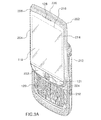
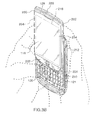
- FIG. 3A and FIG. 3B are perspective views of the example portable electronic device of FIG. 2 , with the display assembly in a second position;
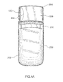
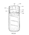
- FIG. 4A and FIG. 4B are rear views of the example portable electronic device of FIG. 2 , with the display assembly in the second position;
- FIG. 5A and FIG. 5B are rear views of another example portable electronic device with the display assembly in a second position
- FIG. 6A and FIG. 6B are rear views of another example portable electronic device with the display assembly in a second position
- FIG. 7A and FIG. 7B are front views of another example portable electronic device with the display assembly in a second position
- FIG. 8 is a side view of the portable electronic device of FIG. 7 with the display assembly in a second position;
- FIG. 9A and FIG 9B are rear views of the portable electronic device of FIG. 7 with the display assembly in a second position.
- the portable electronic device 100 includes multiple components such as a processor 102 that controls the operations of the portable electronic device 100. Communication functions, including data and voice communications, are performed through a communication subsystem 104. Data received by the portable electronic device 100 is decompressed and decrypted by a decoder 106. The communication subsystem 104 receives messages from and sends messages to a wireless network 150.
- the wireless network 150 may be any type of wireless network, including, but not limited to, data-centric wireless networks, voice-centric wireless networks, and dual-mode networks that support both voice and data communications over the same physical base stations.
- the portable electronic device 100 is a battery-powered device and includes a battery interface 142 for receiving one or more rechargeable batteries 144.
- the processor 102 also interacts with additional subsystems such as a Random Access Memory (RAM) 108, a memory 110, a display 112 with a touch-sensitive overlay 114 connected to an electronic controller 116 that together comprise a touch-sensitive display 118, an auxiliary input/output (I/O) subsystem 124, a data port 126, a speaker 128, a keyboard 120, an optical joystick 121, an input device 122, a microphone 130, short-range communications 132 and other device subsystems 134.
- RAM Random Access Memory
- memory 110 a memory 110
- a display 112 with a touch-sensitive overlay 114 connected to an electronic controller 116 that together comprise a touch-sensitive display 118, an auxiliary input/output (I/O) subsystem 124, a data port 126, a speaker 128, a keyboard 120, an optical joystick 121, an input device 122, a microphone 130, short-range communications 132 and other device subsystems 134.
- I/O auxiliary input
- the processor 102 may also interact with an accelerometer 136 as shown in FIG. 1 .
- the accelerometer 136 may include a cantilever beam with a proof mass and suitable deflection sensing circuitry.
- the accelerometer 136 may be utilized for detecting direction of gravitational forces or gravity-induced reaction forces.
- the portable electronic device 100 uses a Subscriber Identity Module or a Removable User Identity Module (SIM/RUIM) card 138 inserted into a SIM/RUIM interface 140 for communication with a network such as the wireless network 150.
- SIM/RUIM Removable User Identity Module
- user identification information may be programmed into the memory 110.
- the portable electronic device 100 also includes an operating system 146 and software components 148 that are executed by the processor 102 and are typically stored in a persistent, updatable store such as memory 110. Additional applications may be loaded onto the portable electronic device 100 through the wireless network 150, the auxiliary I/O subsystem 124, the data port 126, the short-range communications subsystem 132, or any other suitable device subsystem 134.
- a received signal such as a text message, an e-mail message, or web page download is processed by the communication subsystem 104 and input to the processor 102.
- the processor 102 then processes the received signal for output to the display 112 or alternatively to the auxiliary I/O subsystem 124.
- a subscriber may also compose data items, such as e-mail messages, for example, which may be transmitted over the wireless network 150 through the communication subsystem 104.
- voice communications the overall operation of the portable electronic device 100 is similar.
- the speaker 128 outputs audible information converted from electrical signals, and the microphone 130 converts audible information into electrical signals for processing.
- the electronic device 100 generally includes a body 202 and a display assembly 204 that includes a housing 206.
- the display 118 is disposed on one face of the housing 206, and the input device 122 is disposed on an opposing face of the housing 206, adjacent at least one side of the display assembly 204.
- the display assembly 204 is connected to the body 202 and moveable relative to the body 202, between a first position, shown in FIG. 2 , in which the input device 122 is covered by the body 202 and a second position, shown in FIG. 3A , FIG. 3B , FIG. 4A , and FIG. 4B , in which the input device 122 is exposed.
- the body 202 includes a back 208 and a front 210.
- the back 208 may include a plate 209 that is releasably attached for insertion and removal of, for example, the battery 144 and the SIM/RUIM card 138 into the body 202.
- Sides 212 of the body 202 extend between the back 208 and the front 210.
- the sides 212 may include one or more of the auxiliary I/O devices 124 including, for example, a headphone/microphone jack and buttons for input.
- the body 202 includes the keyboard 120.
- the keyboard 120 is located at the front 210 of the body 202 and is covered by the display assembly 204 and hidden between the display assembly 204 and the body 204 when the display assembly 204 is in the second position relative to the body 202. While the keyboard 120 in the present example is a physical keyboard, other input devices may be utilized. For example, a touch-sensitive input surface may be utilized. Further, a full keyboard may be provided, or a reduced keyboard in which alphanumeric characters share keys of the keyboard. Alternatively, a keypad may be utilized.
- the display assembly 204 includes the display 112 which may be an LCD display. Optional components including a backlight may also be included.
- the display 112 in the present example is part of the touch-sensitive display 118, including the touch-sensitive overlay 114 to detect touches thereon.
- the display 112 is framed by a housing 206 of the display assembly 204 and is generally rectangular with opposing parallel long sides 214 and opposing parallel short sides 216.
- the display 112 is housed in the housing 206 such that the display 112 is exposed at the front face, referred to as the front, of the display assembly 204.
- the speaker 128 is located near one end 220 of the housing 206, adjacent a short side 216 of the display 118.
- a further input device is located near the opposite end of the housing 206, adjacent the opposing short side 216 of the display 112.
- the further input device is the optical joystick 121.
- the further input device is optional, however, and other input devices may be utilized such as, for example, a trackball, a touchpad or any other suitable input device.
- a back face 226, also referred to as a back 226, of the display assembly 204 includes the input device 122 which, in the example shown in FIG. 4A and FIG. 4B is a touch-sensitive input device 122.
- the touch-sensitive input device includes, for example, a touch-sensitive overlay disposed on a back surface of the housing 206 of the display assembly 204.
- the touch-sensitive input device 122 is semicircular and is located on the back surface of the housing 206, near one side.
- the touch-sensitive input device 122 may be similar to the touch-sensitive overlay 114 and may be connected to the main processor 102 via a separate controller or may be connected via the controller 116 that connects the overlay 114 of the touch-sensitive display 118.
- the touch-sensitive input device 122 is a capacitive touchpad that includes layers in a stack. The layers include, for example, a protective cover and touch sensor layers separated by an insulating layer.
- a guide 228 is located around the periphery of the touch-sensitive input device 122.
- the guide 228 may be a ridge, which may be formed in the back surface of the housing 206, for example, to facilitate tactilely locating the touch-sensitive input device 122 when the portable electronic device 100 is in use.
- the guide is not limited to a ridge as other guides such as depressions or dimples may be utilized around the touch-sensitive input device 122, or incorporated into the touch-sensitive input device 122 for tactilely locating the touch-sensitive input device 122.
- the display assembly 204 is moveably connected to the body 202 in any suitable manner such that the display assembly 204 is moveable from the first position to the second position.
- the display assembly 204 may include a slide plate at the back 226, along which the body 202 may slide.
- the body 202 may include a slot in which a projection, that projects from the back 226 of the display assembly 204, may slide.
- the display assembly 204 may be connected to the body 202 and may rotate and translate utilizing a rack and pinion mechanism that forms part of the body 202 and display assembly 204. Still other connections may be utilized to facilitate movement of the display assembly 204 relative to the body 202, between the first and second positions.
- the display assembly 204 is moveable relative to the body 202, between the first position shown in FIG. 2 and the second position shown in FIG. 3A , FIG. 3B , FIG. 4A , and FIG. 4B .
- the front 210 of the body 202 is hidden by the display assembly 204 and the touch-sensitive input device 122 is disposed on the back 226 of the display assembly 206 and hidden by the body 202.
- the keyboard 120 is exposed for input and the touch-sensitive input device 122 is exposed at the back 226 of the housing 206 as a result of the translational movement of the display assembly 204 relative to the body 202.
- the user may hold or cradle the portable electronic device 100 for input utilizing, for example, the keyboard 120, as shown in FIG. 3B .
- the touch-sensitive input device 122 may also be utilized, for example, for navigation such as scrolling of a cursor.
- the touch-sensitive input device 122 may be utilized by touching, for example, with a forefinger (also referred to as the index finger), as shown in FIG. 4B , for navigation through a GUI while cradling the portable electronic device 100, for example, for thumb input utilizing the keyboard 120.
- the location of the input device 122 adjacent one side of the display assembly 204 facilitates use of both the input device 122 and the keyboard 120 when the device is cradled as described.
- the input device 122 may therefore be used without repositioning a hand or hands during use of the portable electronic device 100. Use of the portable electronic device 100 is thereby facilitated without having to reposition a hand or hands between typing and input utilizing the input device 122, thereby reducing device use and power consumption.
- the input device 122 is not limited to the touch-sensitive input device 122 shown in FIG. 4A and FIG. 4B .
- Multiple touch-sensitive input devices 122 may be utilized on the back 226 of the display assembly 204, as shown in FIG. 5A and FIG. 5B , which shows two touch-sensitive areas 502.
- the touch-sensitive areas 502 in the example of FIG. 5A and FIG. 5B are semicircular and each of the touch-sensitive areas 502 is located adjacent a respective one of opposing sides of the housing 206.
- Guides 504 are located around the periphery of each area 502.
- the touch-sensitive input areas 502 may be utilized by touching, for example, with a forefinger (also referred to as the index finger), as shown in FIG. 5B , for navigation through a GUI while cradling the portable electronic device 100, for example, for thumb input utilizing the keyboard 120.
- the location of the input areas 502 adjacent each side of the display assembly 204 facilitates use of both the input areas 502 and the keyboard 120 when the device is cradled as described.
- the input areas 502 may therefore be used without repositioning a hand or hands during use of the portable electronic device 100. Use of the portable electronic device 100 is thereby facilitated without having to reposition a hand or hands between typing and input utilizing the input areas 502, thereby reducing device use and power consumption.
- FIG. 6A and FIG. 6B show yet another example of a touch-sensitive input device 122.
- the touch-sensitive input device 122 comprises a generally rectangular touchpad 602 on the back surface of the housing 206.
- the touchpad 602 extends across the width of the back 226 of the housing 206 such that the touchpad 602 is adjacent both of the opposing sides of the housing 206.
- the touchpad 602 may be utilized by touching, for example, with a forefinger (also referred to as the index finger) or with both forefingers, as shown in FIG. 6B , for navigation through a GUI while cradling the portable electronic device 100, for example, for thumb input utilizing the keyboard 120.
- the location of the touchpad 602 adjacent each side of the display assembly 204 facilitates use of both the input areas 502 and the keyboard 120 when the device is cradled as described.
- the touchpad 602 may therefore be used without repositioning a hand or hands during use of the portable electronic device 100. Use of the portable electronic device 100 is thereby facilitated without having to reposition a hand or hands between typing and input utilizing the touchpad 602, thereby reducing device use and power consumption.
- FIG. 7A , FIG. 7B , FIG. 8, FIG. 9A , and FIG. 9B show a front view, a side view and back view of a portable electronic device 100 according to another example.
- the portable electronic device 100 of the present example includes similar features to the portable electronic device shown and described above with reference to FIG. 2 , FIG. 3A , FIG. 3B , FIG. 4A , and FIG. 4B .
- the body 202 and the display assembly 204 slide relative to each other such that the display 112 is in the landscape orientation when the keyboard 120 is utilized for typing.
- the keyboard 120 is located below a long side of the display 112.
- the touch-sensitive input device 122 is exposed when in the second position and comprises a generally rectangular touchpad at the back of the housing 206.
- the touchpad extends across the width of the back of the housing such that the touchpad is adjacent both of the opposing sides short of the housing.
- the user may hold or cradle the portable electronic device 100 for input utilizing, for example, the keyboard 120, as shown in FIG. 7B .
- the touch-sensitive input device 122 may also be utilized, for example, for navigation such as scrolling of a cursor.
- the touch-sensitive input device 122 may be utilized by touching, for example, with either of the two forefingers or with both forefingers, as shown in FIG. 9B , for navigation through a GUI while cradling the portable electronic device 100, for example, for thumb input utilizing the keyboard 120.
- the location of the input device 122 adjacent the sides of the display assembly 204 facilitates use of both the input device 122 and the keyboard 120 when the device is cradled as described.
- the input device 122 may therefore be used without repositioning a hand or hands during use of the portable electronic device 100. Use of the portable electronic device 100 is thereby facilitated without having to reposition a hand or hands between typing and input utilizing the input device 122, thereby reducing device use and power consumption.
- touch-sensitive input devices including, for example, a trackball, an optical joystick, a trackwheel, a touch-sensitive pad, a track bar, and any combination of these input devices.
- the portable electronic device described herein includes a body and a display assembly moveable relative to the body. In the first position, a keyboard and an input device are hidden. In a second position, the display assembly is moved relative to the body and the keyboard of the body is exposed and the input device is exposed on the back of the display assembly.
- the input device on the back of the display assembly provides further input for the portable electronic device on an area of the portable electronic device that may not be otherwise utilized. Further, the location of the input device facilitates cradling of the device for thumb input utilizing the keyboard and for forefinger input utilizing the input device, while holding the back of the portable electronic device with the remaining fingers, without repositioning either or both of the hands. Thus, the forefinger or forefingers may reach the input device without repositioning, saving device use time and power consumption.
Landscapes
- Engineering & Computer Science (AREA)
- Theoretical Computer Science (AREA)
- Computer Hardware Design (AREA)
- Physics & Mathematics (AREA)
- General Engineering & Computer Science (AREA)
- General Physics & Mathematics (AREA)
- Human Computer Interaction (AREA)
- Signal Processing (AREA)
- Mathematical Physics (AREA)
- Position Input By Displaying (AREA)
- User Interface Of Digital Computer (AREA)
- Input From Keyboards Or The Like (AREA)
- Telephone Set Structure (AREA)
Abstract
Description
- The present disclosure relates to electronic devices, including but not limited to electronic devices that have touch-sensitive displays.
- Electronic devices, including portable electronic devices, have gained widespread use and may provide a variety of functions including, for example, telephonic, electronic text messaging and other personal information manager (PIM) application functions. Portable electronic devices can include several types of devices including mobile stations such as simple cellular phones, smart phones, Personal Digital Assistants (PDAs), and laptop computers.
- Devices such as PDAs or smart phones are generally intended for handheld use and ease of portability. Smaller devices are generally desirable for portability. Touch-sensitive devices constructed of a display, such as a liquid crystal display (LCD), with a touch-sensitive overlay are useful on such handheld devices as such handheld devices are small and are therefore limited in space available for user input and output devices. Further, the screen content on the touch-sensitive devices can be modified depending on the functions and operations being performed.
- Improvements in portable electronic devices are desirable.
- According to one aspect, an electronic device is provided. The electronic device includes a body and a display assembly. The display assembly includes a housing, a display on one side of the housing, and a first input device on an opposing side of the housing. The display assembly is connected to the body and is moveable relative to the body, between a first position in which the input device is covered by the body and a second position in which the input device is exposed.
- Embodiments of the present disclosure will now be described, by way of example only, with reference to the attached Figures, wherein:
-
FIG. 1 is a simplified block diagram of components including internal components of a portable electronic device according to an example embodiment; -
FIG. 2 is a perspective view of an example of a portable electronic device including a display assembly in a first position; -
FIG. 3A andFIG. 3B are perspective views of the example portable electronic device ofFIG. 2 , with the display assembly in a second position; -
FIG. 4A andFIG. 4B are rear views of the example portable electronic device ofFIG. 2 , with the display assembly in the second position; -
FIG. 5A andFIG. 5B are rear views of another example portable electronic device with the display assembly in a second position; -
FIG. 6A andFIG. 6B are rear views of another example portable electronic device with the display assembly in a second position; -
FIG. 7A andFIG. 7B are front views of another example portable electronic device with the display assembly in a second position; -
FIG. 8 is a side view of the portable electronic device ofFIG. 7 with the display assembly in a second position; and -
FIG. 9A andFIG 9B are rear views of the portable electronic device ofFIG. 7 with the display assembly in a second position. - It will be appreciated that for simplicity and clarity of illustration, where considered appropriate, reference numerals may be repeated among the figures to indicate corresponding or analogous elements. In addition, numerous specific details are set forth in order to provide a thorough understanding of the example embodiments described herein. However, it will be understood by those of ordinary skill in the art that the example embodiments described herein may be practiced without these specific details. In other instances, well-known methods, procedures and components have not been described in detail so as not to obscure the example embodiments described herein. Also, the description is not to be considered as limited to the scope of the example embodiments described herein.
- Referring first to
FIG. 1 , a block diagram of components of the portableelectronic device 100 is shown. The portableelectronic device 100 includes multiple components such as aprocessor 102 that controls the operations of the portableelectronic device 100. Communication functions, including data and voice communications, are performed through acommunication subsystem 104. Data received by the portableelectronic device 100 is decompressed and decrypted by adecoder 106. Thecommunication subsystem 104 receives messages from and sends messages to awireless network 150. Thewireless network 150 may be any type of wireless network, including, but not limited to, data-centric wireless networks, voice-centric wireless networks, and dual-mode networks that support both voice and data communications over the same physical base stations. The portableelectronic device 100 is a battery-powered device and includes a battery interface 142 for receiving one or morerechargeable batteries 144. - The
processor 102 also interacts with additional subsystems such as a Random Access Memory (RAM) 108, amemory 110, adisplay 112 with a touch-sensitive overlay 114 connected to anelectronic controller 116 that together comprise a touch-sensitive display 118, an auxiliary input/output (I/O)subsystem 124, a data port 126, aspeaker 128, akeyboard 120, anoptical joystick 121, aninput device 122, amicrophone 130, short-range communications 132 andother device subsystems 134. User-interaction with the graphical user interface is performed through the touch-sensitive overlay 114. Theprocessor 102 interacts with the touch-sensitive overlay 114 via theelectronic controller 116. Information, such as text, characters, symbols, images, icons, and other features that may be displayed or rendered on a portable electronic device, are displayed on the touch-sensitive display 118 via theprocessor 102. Theprocessor 102 may also interact with anaccelerometer 136 as shown inFIG. 1 . Theaccelerometer 136 may include a cantilever beam with a proof mass and suitable deflection sensing circuitry. Theaccelerometer 136 may be utilized for detecting direction of gravitational forces or gravity-induced reaction forces. - To identify a subscriber for network access according to the present embodiment, the portable
electronic device 100 uses a Subscriber Identity Module or a Removable User Identity Module (SIM/RUIM)card 138 inserted into a SIM/RUIM interface 140 for communication with a network such as thewireless network 150. Alternatively, user identification information may be programmed into thememory 110. - The portable
electronic device 100 also includes an operating system 146 andsoftware components 148 that are executed by theprocessor 102 and are typically stored in a persistent, updatable store such asmemory 110. Additional applications may be loaded onto the portableelectronic device 100 through thewireless network 150, the auxiliary I/O subsystem 124, the data port 126, the short-range communications subsystem 132, or any othersuitable device subsystem 134. - In use, a received signal such as a text message, an e-mail message, or web page download is processed by the
communication subsystem 104 and input to theprocessor 102. Theprocessor 102 then processes the received signal for output to thedisplay 112 or alternatively to the auxiliary I/O subsystem 124. A subscriber may also compose data items, such as e-mail messages, for example, which may be transmitted over thewireless network 150 through thecommunication subsystem 104. For voice communications, the overall operation of the portableelectronic device 100 is similar. Thespeaker 128 outputs audible information converted from electrical signals, and themicrophone 130 converts audible information into electrical signals for processing. - Referring to
FIG. 2 through FIG. 4B , perspective views of an example of the portableelectronic device 100 are shown. Theelectronic device 100 generally includes abody 202 and adisplay assembly 204 that includes ahousing 206. Thedisplay 118 is disposed on one face of thehousing 206, and theinput device 122 is disposed on an opposing face of thehousing 206, adjacent at least one side of thedisplay assembly 204. Thedisplay assembly 204 is connected to thebody 202 and moveable relative to thebody 202, between a first position, shown inFIG. 2 , in which theinput device 122 is covered by thebody 202 and a second position, shown inFIG. 3A ,FIG. 3B ,FIG. 4A , andFIG. 4B , in which theinput device 122 is exposed. - The
body 202 includes a back 208 and a front 210. The back 208 may include aplate 209 that is releasably attached for insertion and removal of, for example, thebattery 144 and the SIM/RUIM card 138 into thebody 202.Sides 212 of thebody 202 extend between the back 208 and the front 210. Thesides 212 may include one or more of the auxiliary I/O devices 124 including, for example, a headphone/microphone jack and buttons for input. In the present example, thebody 202 includes thekeyboard 120. Thekeyboard 120 is located at thefront 210 of thebody 202 and is covered by thedisplay assembly 204 and hidden between thedisplay assembly 204 and thebody 204 when thedisplay assembly 204 is in the second position relative to thebody 202. While thekeyboard 120 in the present example is a physical keyboard, other input devices may be utilized. For example, a touch-sensitive input surface may be utilized. Further, a full keyboard may be provided, or a reduced keyboard in which alphanumeric characters share keys of the keyboard. Alternatively, a keypad may be utilized. - The
display assembly 204 includes thedisplay 112 which may be an LCD display. Optional components including a backlight may also be included. Thedisplay 112 in the present example, is part of the touch-sensitive display 118, including the touch-sensitive overlay 114 to detect touches thereon. Thedisplay 112 is framed by ahousing 206 of thedisplay assembly 204 and is generally rectangular with opposing parallellong sides 214 and opposing parallelshort sides 216. Thedisplay 112 is housed in thehousing 206 such that thedisplay 112 is exposed at the front face, referred to as the front, of thedisplay assembly 204. Thespeaker 128 is located near oneend 220 of thehousing 206, adjacent ashort side 216 of thedisplay 118. A further input device is located near the opposite end of thehousing 206, adjacent the opposingshort side 216 of thedisplay 112. In the present embodiment, the further input device is theoptical joystick 121. The further input device is optional, however, and other input devices may be utilized such as, for example, a trackball, a touchpad or any other suitable input device. - A
back face 226, also referred to as a back 226, of thedisplay assembly 204 includes theinput device 122 which, in the example shown inFIG. 4A andFIG. 4B is a touch-sensitive input device 122. The touch-sensitive input device includes, for example, a touch-sensitive overlay disposed on a back surface of thehousing 206 of thedisplay assembly 204. For the purpose of the present example, the touch-sensitive input device 122 is semicircular and is located on the back surface of thehousing 206, near one side. The touch-sensitive input device 122 may be similar to the touch-sensitive overlay 114 and may be connected to themain processor 102 via a separate controller or may be connected via thecontroller 116 that connects theoverlay 114 of the touch-sensitive display 118. In the present example, the touch-sensitive input device 122 is a capacitive touchpad that includes layers in a stack. The layers include, for example, a protective cover and touch sensor layers separated by an insulating layer. - A guide 228 is located around the periphery of the touch-
sensitive input device 122. The guide 228 may be a ridge, which may be formed in the back surface of thehousing 206, for example, to facilitate tactilely locating the touch-sensitive input device 122 when the portableelectronic device 100 is in use. The guide is not limited to a ridge as other guides such as depressions or dimples may be utilized around the touch-sensitive input device 122, or incorporated into the touch-sensitive input device 122 for tactilely locating the touch-sensitive input device 122. - The
display assembly 204 is moveably connected to thebody 202 in any suitable manner such that thedisplay assembly 204 is moveable from the first position to the second position. For example, thedisplay assembly 204 may include a slide plate at the back 226, along which thebody 202 may slide. Alternatively, thebody 202 may include a slot in which a projection, that projects from the back 226 of thedisplay assembly 204, may slide. In yet another example, thedisplay assembly 204 may be connected to thebody 202 and may rotate and translate utilizing a rack and pinion mechanism that forms part of thebody 202 anddisplay assembly 204. Still other connections may be utilized to facilitate movement of thedisplay assembly 204 relative to thebody 202, between the first and second positions. - As described above, the
display assembly 204 is moveable relative to thebody 202, between the first position shown inFIG. 2 and the second position shown inFIG. 3A ,FIG. 3B ,FIG. 4A , andFIG. 4B . In the position shown inFIG. 2 , thefront 210 of thebody 202 is hidden by thedisplay assembly 204 and the touch-sensitive input device 122 is disposed on the back 226 of thedisplay assembly 206 and hidden by thebody 202. When the display assembly is moved to the second position shown inFIG. 3 andFIG. 4 , thekeyboard 120 is exposed for input and the touch-sensitive input device 122 is exposed at the back 226 of thehousing 206 as a result of the translational movement of thedisplay assembly 204 relative to thebody 202. - In use, the user may hold or cradle the portable
electronic device 100 for input utilizing, for example, thekeyboard 120, as shown inFIG. 3B . The touch-sensitive input device 122 may also be utilized, for example, for navigation such as scrolling of a cursor. The touch-sensitive input device 122 may be utilized by touching, for example, with a forefinger (also referred to as the index finger), as shown inFIG. 4B , for navigation through a GUI while cradling the portableelectronic device 100, for example, for thumb input utilizing thekeyboard 120. The location of theinput device 122 adjacent one side of thedisplay assembly 204 facilitates use of both theinput device 122 and thekeyboard 120 when the device is cradled as described. Theinput device 122 may therefore be used without repositioning a hand or hands during use of the portableelectronic device 100. Use of the portableelectronic device 100 is thereby facilitated without having to reposition a hand or hands between typing and input utilizing theinput device 122, thereby reducing device use and power consumption. - The
input device 122 is not limited to the touch-sensitive input device 122 shown inFIG. 4A andFIG. 4B . Multiple touch-sensitive input devices 122 may be utilized on the back 226 of thedisplay assembly 204, as shown inFIG. 5A andFIG. 5B , which shows two touch-sensitive areas 502. The touch-sensitive areas 502 in the example ofFIG. 5A andFIG. 5B are semicircular and each of the touch-sensitive areas 502 is located adjacent a respective one of opposing sides of thehousing 206.Guides 504 are located around the periphery of eacharea 502. - The touch-
sensitive input areas 502 may be utilized by touching, for example, with a forefinger (also referred to as the index finger), as shown inFIG. 5B , for navigation through a GUI while cradling the portableelectronic device 100, for example, for thumb input utilizing thekeyboard 120. The location of theinput areas 502 adjacent each side of thedisplay assembly 204 facilitates use of both theinput areas 502 and thekeyboard 120 when the device is cradled as described. Theinput areas 502 may therefore be used without repositioning a hand or hands during use of the portableelectronic device 100. Use of the portableelectronic device 100 is thereby facilitated without having to reposition a hand or hands between typing and input utilizing theinput areas 502, thereby reducing device use and power consumption. -
FIG. 6A andFIG. 6B show yet another example of a touch-sensitive input device 122. In the present example, the touch-sensitive input device 122 comprises a generallyrectangular touchpad 602 on the back surface of thehousing 206. Thetouchpad 602 extends across the width of the back 226 of thehousing 206 such that thetouchpad 602 is adjacent both of the opposing sides of thehousing 206. - The
touchpad 602 may be utilized by touching, for example, with a forefinger (also referred to as the index finger) or with both forefingers, as shown inFIG. 6B , for navigation through a GUI while cradling the portableelectronic device 100, for example, for thumb input utilizing thekeyboard 120. The location of thetouchpad 602 adjacent each side of thedisplay assembly 204 facilitates use of both theinput areas 502 and thekeyboard 120 when the device is cradled as described. Thetouchpad 602 may therefore be used without repositioning a hand or hands during use of the portableelectronic device 100. Use of the portableelectronic device 100 is thereby facilitated without having to reposition a hand or hands between typing and input utilizing thetouchpad 602, thereby reducing device use and power consumption. -
FIG. 7A ,FIG. 7B ,FIG. 8, FIG. 9A , andFIG. 9B show a front view, a side view and back view of a portableelectronic device 100 according to another example. The portableelectronic device 100 of the present example includes similar features to the portable electronic device shown and described above with reference toFIG. 2 ,FIG. 3A ,FIG. 3B ,FIG. 4A , andFIG. 4B . In the present example, however, thebody 202 and thedisplay assembly 204 slide relative to each other such that thedisplay 112 is in the landscape orientation when thekeyboard 120 is utilized for typing. Thus, when the portableelectronic device 100 is held in the orientation in which thekeyboard 120 is upright, thekeyboard 120 is located below a long side of thedisplay 112. The touch-sensitive input device 122 is exposed when in the second position and comprises a generally rectangular touchpad at the back of thehousing 206. The touchpad extends across the width of the back of the housing such that the touchpad is adjacent both of the opposing sides short of the housing. - As in the first-described example, the user may hold or cradle the portable
electronic device 100 for input utilizing, for example, thekeyboard 120, as shown inFIG. 7B . The touch-sensitive input device 122 may also be utilized, for example, for navigation such as scrolling of a cursor. The touch-sensitive input device 122 may be utilized by touching, for example, with either of the two forefingers or with both forefingers, as shown inFIG. 9B , for navigation through a GUI while cradling the portableelectronic device 100, for example, for thumb input utilizing thekeyboard 120. The location of theinput device 122 adjacent the sides of thedisplay assembly 204 facilitates use of both theinput device 122 and thekeyboard 120 when the device is cradled as described. Theinput device 122 may therefore be used without repositioning a hand or hands during use of the portableelectronic device 100. Use of the portableelectronic device 100 is thereby facilitated without having to reposition a hand or hands between typing and input utilizing theinput device 122, thereby reducing device use and power consumption. - Still other touch-sensitive input devices may be utilized including, for example, a trackball, an optical joystick, a trackwheel, a touch-sensitive pad, a track bar, and any combination of these input devices.
- The portable electronic device described herein includes a body and a display assembly moveable relative to the body. In the first position, a keyboard and an input device are hidden. In a second position, the display assembly is moved relative to the body and the keyboard of the body is exposed and the input device is exposed on the back of the display assembly. The input device on the back of the display assembly provides further input for the portable electronic device on an area of the portable electronic device that may not be otherwise utilized. Further, the location of the input device facilitates cradling of the device for thumb input utilizing the keyboard and for forefinger input utilizing the input device, while holding the back of the portable electronic device with the remaining fingers, without repositioning either or both of the hands. Thus, the forefinger or forefingers may reach the input device without repositioning, saving device use time and power consumption.
- While the embodiments described herein are directed to particular implementations of the actuating assembly and the portable electronic device and the, it will be understood that modifications and variations may occur to those skilled in the art. All such modifications and variations are believed to be within the sphere and scope of the present disclosure.
Claims (12)
- An electronic device comprising:a body;a display assembly comprising a housing, a display on one face of the housing, and a first input device located on an opposing face of the housing, adjacent at least one side of the display assembly, the display assembly connected to the body and moveable relative to the body, between a first position in which the first input device is covered by the body and a second position in which the input device is exposed.
- The electronic device according to claim 1, wherein the body comprises a second input device, the second input device located adjacent an opposite side of the display assembly as the first input device.
- The electronic device according to claim 2, wherein the second input device is covered by the display assembly when the display assembly is in the first position and exposed when the display assembly is in the second position.
- The electronic device according to any of claims 1 to 3, wherein the body comprises a keyboard.
- The electronic device according to any of claims 1 to 4, wherein the display comprises a touch-sensitive display.
- The electronic device according to any of claims 1 to 5, wherein the display assembly comprises a touch-sensitive overlay disposed on the display.
- The electronic device according to any of claims 1 to 6, wherein the first input device comprises a touch-sensitive input device.
- The electronic device according to claim 7, wherein the display assembly comprises a guide for tactilely locating the first input device.
- The electronic device according to any of claims 1 to 8, wherein the first input device comprises a plurality of touch-sensitive areas on the opposing side of the housing.
- The electronic device according to claim 9, wherein the display assembly comprises a plurality of guides for tactilely locating the touch-sensitive areas.
- The electronic device according to any of claims 1 to 10, wherein the first input device comprises at least one of a trackball, an optical joystick, a trackwheel, a touch-sensitive pad, and a track bar.
- The electronic device according to any of claims 1 to 11, wherein the first input device extends across the opposing face of the display assembly such that the first input device is adjacent opposing sides of the display assembly.
Priority Applications (2)
| Application Number | Priority Date | Filing Date | Title |
|---|---|---|---|
| EP20100161671 EP2383964B1 (en) | 2010-04-30 | 2010-04-30 | Electronic device |
| CA2735051A CA2735051C (en) | 2010-04-30 | 2011-03-23 | Electronic device |
Applications Claiming Priority (1)
| Application Number | Priority Date | Filing Date | Title |
|---|---|---|---|
| EP20100161671 EP2383964B1 (en) | 2010-04-30 | 2010-04-30 | Electronic device |
Publications (2)
| Publication Number | Publication Date |
|---|---|
| EP2383964A1 true EP2383964A1 (en) | 2011-11-02 |
| EP2383964B1 EP2383964B1 (en) | 2012-12-19 |
Family
ID=42740367
Family Applications (1)
| Application Number | Title | Priority Date | Filing Date |
|---|---|---|---|
| EP20100161671 Active EP2383964B1 (en) | 2010-04-30 | 2010-04-30 | Electronic device |
Country Status (2)
| Country | Link |
|---|---|
| EP (1) | EP2383964B1 (en) |
| CA (1) | CA2735051C (en) |
Citations (3)
| Publication number | Priority date | Publication date | Assignee | Title |
|---|---|---|---|---|
| EP0913977A2 (en) * | 1997-10-31 | 1999-05-06 | Nokia Mobile Phones Ltd. | A radiotelephone handset |
| GB2393066A (en) * | 2001-10-03 | 2004-03-17 | Nec Corp | Camera and/or fingerprint recognition device located on sliding portion of portable communication device |
| US20070142102A1 (en) * | 2005-12-19 | 2007-06-21 | Samsung Electronics Co., Ltd. | Mobile communication terminal having multiple keypads and main body thereof |
-
2010
- 2010-04-30 EP EP20100161671 patent/EP2383964B1/en active Active
-
2011
- 2011-03-23 CA CA2735051A patent/CA2735051C/en active Active
Patent Citations (3)
| Publication number | Priority date | Publication date | Assignee | Title |
|---|---|---|---|---|
| EP0913977A2 (en) * | 1997-10-31 | 1999-05-06 | Nokia Mobile Phones Ltd. | A radiotelephone handset |
| GB2393066A (en) * | 2001-10-03 | 2004-03-17 | Nec Corp | Camera and/or fingerprint recognition device located on sliding portion of portable communication device |
| US20070142102A1 (en) * | 2005-12-19 | 2007-06-21 | Samsung Electronics Co., Ltd. | Mobile communication terminal having multiple keypads and main body thereof |
Also Published As
| Publication number | Publication date |
|---|---|
| EP2383964B1 (en) | 2012-12-19 |
| CA2735051A1 (en) | 2011-10-30 |
| CA2735051C (en) | 2014-12-09 |
Similar Documents
| Publication | Publication Date | Title |
|---|---|---|
| US8179376B2 (en) | Touch-sensitive display with capacitive and resistive touch sensors and method of control | |
| US9213428B2 (en) | Portable electronic device including flexible display | |
| CA2756821C (en) | Portable electronic device including flexible display | |
| EP2387208B1 (en) | Handheld electronic communication device | |
| US8619043B2 (en) | System and method of calibration of a touch screen display | |
| EP3051407A1 (en) | Electronic device and method of controlling display of information | |
| CA2709440C (en) | Touch-sensitive display with capacitive and resistive touch sensors and method of control | |
| US20100220066A1 (en) | Handheld electronic device having a touchscreen and a method of using a touchscreen of a handheld electronic device | |
| US7715191B2 (en) | Handheld electronic communication device transitionable between compact and expanded configurations | |
| KR20120024299A (en) | Method for providing user interface and mobile terminal using this method | |
| US20120127075A1 (en) | Segmented portable electronic device and method of display | |
| US8698761B2 (en) | Electronic device | |
| EP2360899A2 (en) | Slidable electronic device including touch-sensitive display | |
| CA2689845C (en) | System and method of calibration of a touch screen display | |
| CA2735051C (en) | Electronic device | |
| US10061394B2 (en) | Electronic device including keypad with keys having a ridged surface profile | |
| CA2756548C (en) | Segmented portable electronic device and method of display | |
| US8723814B2 (en) | Handheld electronic communication device | |
| KR101500503B1 (en) | A portable terminal and its operation method | |
| EP2495943B1 (en) | Slidable and rotatable portable electronic device for aligning the surfaces of the keypad and display portions | |
| CA2768202C (en) | Portable electronic device slidable in a plurality of directions for aligning the surfaces of the keypad and display portions | |
| CA2761454A1 (en) | Portable electronic device including touch-sensitive display | |
| CA2766875C (en) | Portable electronic device and method of controlling same | |
| CA2655066C (en) | Handheld electronic communication device transitionable between compact and expanded configurations | |
| KR20100045321A (en) | Apparatus and method for controlling vibration of mobile terminal |
Legal Events
| Date | Code | Title | Description |
|---|---|---|---|
| 17P | Request for examination filed |
Effective date: 20100430 |
|
| AK | Designated contracting states |
Kind code of ref document: A1 Designated state(s): AT BE BG CH CY CZ DE DK EE ES FI FR GB GR HR HU IE IS IT LI LT LU LV MC MK MT NL NO PL PT RO SE SI SK SM TR |
|
| AX | Request for extension of the european patent |
Extension state: AL BA ME RS |
|
| PUAI | Public reference made under article 153(3) epc to a published international application that has entered the european phase |
Free format text: ORIGINAL CODE: 0009012 |
|
| GRAP | Despatch of communication of intention to grant a patent |
Free format text: ORIGINAL CODE: EPIDOSNIGR1 |
|
| GRAS | Grant fee paid |
Free format text: ORIGINAL CODE: EPIDOSNIGR3 |
|
| GRAA | (expected) grant |
Free format text: ORIGINAL CODE: 0009210 |
|
| AK | Designated contracting states |
Kind code of ref document: B1 Designated state(s): AT BE BG CH CY CZ DE DK EE ES FI FR GB GR HR HU IE IS IT LI LT LU LV MC MK MT NL NO PL PT RO SE SI SK SM TR |
|
| REG | Reference to a national code |
Ref country code: GB Ref legal event code: FG4D |
|
| REG | Reference to a national code |
Ref country code: CH Ref legal event code: EP |
|
| REG | Reference to a national code |
Ref country code: AT Ref legal event code: REF Ref document number: 589892 Country of ref document: AT Kind code of ref document: T Effective date: 20130115 |
|
| REG | Reference to a national code |
Ref country code: DE Ref legal event code: R096 Ref document number: 602010004148 Country of ref document: DE Effective date: 20130207 |
|
| PG25 | Lapsed in a contracting state [announced via postgrant information from national office to epo] |
Ref country code: FI Free format text: LAPSE BECAUSE OF FAILURE TO SUBMIT A TRANSLATION OF THE DESCRIPTION OR TO PAY THE FEE WITHIN THE PRESCRIBED TIME-LIMIT Effective date: 20121219 Ref country code: ES Free format text: LAPSE BECAUSE OF FAILURE TO SUBMIT A TRANSLATION OF THE DESCRIPTION OR TO PAY THE FEE WITHIN THE PRESCRIBED TIME-LIMIT Effective date: 20130330 Ref country code: NO Free format text: LAPSE BECAUSE OF FAILURE TO SUBMIT A TRANSLATION OF THE DESCRIPTION OR TO PAY THE FEE WITHIN THE PRESCRIBED TIME-LIMIT Effective date: 20130319 Ref country code: LT Free format text: LAPSE BECAUSE OF FAILURE TO SUBMIT A TRANSLATION OF THE DESCRIPTION OR TO PAY THE FEE WITHIN THE PRESCRIBED TIME-LIMIT Effective date: 20121219 Ref country code: HR Free format text: LAPSE BECAUSE OF FAILURE TO SUBMIT A TRANSLATION OF THE DESCRIPTION OR TO PAY THE FEE WITHIN THE PRESCRIBED TIME-LIMIT Effective date: 20121219 Ref country code: SE Free format text: LAPSE BECAUSE OF FAILURE TO SUBMIT A TRANSLATION OF THE DESCRIPTION OR TO PAY THE FEE WITHIN THE PRESCRIBED TIME-LIMIT Effective date: 20121219 |
|
| REG | Reference to a national code |
Ref country code: NL Ref legal event code: T3 |
|
| REG | Reference to a national code |
Ref country code: AT Ref legal event code: MK05 Ref document number: 589892 Country of ref document: AT Kind code of ref document: T Effective date: 20121219 |
|
| REG | Reference to a national code |
Ref country code: LT Ref legal event code: MG4D |
|
| PG25 | Lapsed in a contracting state [announced via postgrant information from national office to epo] |
Ref country code: LV Free format text: LAPSE BECAUSE OF FAILURE TO SUBMIT A TRANSLATION OF THE DESCRIPTION OR TO PAY THE FEE WITHIN THE PRESCRIBED TIME-LIMIT Effective date: 20121219 Ref country code: GR Free format text: LAPSE BECAUSE OF FAILURE TO SUBMIT A TRANSLATION OF THE DESCRIPTION OR TO PAY THE FEE WITHIN THE PRESCRIBED TIME-LIMIT Effective date: 20130320 Ref country code: SI Free format text: LAPSE BECAUSE OF FAILURE TO SUBMIT A TRANSLATION OF THE DESCRIPTION OR TO PAY THE FEE WITHIN THE PRESCRIBED TIME-LIMIT Effective date: 20121219 |
|
| PG25 | Lapsed in a contracting state [announced via postgrant information from national office to epo] |
Ref country code: EE Free format text: LAPSE BECAUSE OF FAILURE TO SUBMIT A TRANSLATION OF THE DESCRIPTION OR TO PAY THE FEE WITHIN THE PRESCRIBED TIME-LIMIT Effective date: 20121219 Ref country code: AT Free format text: LAPSE BECAUSE OF FAILURE TO SUBMIT A TRANSLATION OF THE DESCRIPTION OR TO PAY THE FEE WITHIN THE PRESCRIBED TIME-LIMIT Effective date: 20121219 Ref country code: CZ Free format text: LAPSE BECAUSE OF FAILURE TO SUBMIT A TRANSLATION OF THE DESCRIPTION OR TO PAY THE FEE WITHIN THE PRESCRIBED TIME-LIMIT Effective date: 20121219 Ref country code: SK Free format text: LAPSE BECAUSE OF FAILURE TO SUBMIT A TRANSLATION OF THE DESCRIPTION OR TO PAY THE FEE WITHIN THE PRESCRIBED TIME-LIMIT Effective date: 20121219 Ref country code: BE Free format text: LAPSE BECAUSE OF FAILURE TO SUBMIT A TRANSLATION OF THE DESCRIPTION OR TO PAY THE FEE WITHIN THE PRESCRIBED TIME-LIMIT Effective date: 20121219 Ref country code: IS Free format text: LAPSE BECAUSE OF FAILURE TO SUBMIT A TRANSLATION OF THE DESCRIPTION OR TO PAY THE FEE WITHIN THE PRESCRIBED TIME-LIMIT Effective date: 20130419 Ref country code: BG Free format text: LAPSE BECAUSE OF FAILURE TO SUBMIT A TRANSLATION OF THE DESCRIPTION OR TO PAY THE FEE WITHIN THE PRESCRIBED TIME-LIMIT Effective date: 20130319 |
|
| REG | Reference to a national code |
Ref country code: CH Ref legal event code: PFA Owner name: BLACKBERRY LIMITED, CA Free format text: FORMER OWNER: RESEARCH IN MOTION LIMITED, CA |
|
| PG25 | Lapsed in a contracting state [announced via postgrant information from national office to epo] |
Ref country code: PT Free format text: LAPSE BECAUSE OF FAILURE TO SUBMIT A TRANSLATION OF THE DESCRIPTION OR TO PAY THE FEE WITHIN THE PRESCRIBED TIME-LIMIT Effective date: 20130419 Ref country code: PL Free format text: LAPSE BECAUSE OF FAILURE TO SUBMIT A TRANSLATION OF THE DESCRIPTION OR TO PAY THE FEE WITHIN THE PRESCRIBED TIME-LIMIT Effective date: 20121219 Ref country code: RO Free format text: LAPSE BECAUSE OF FAILURE TO SUBMIT A TRANSLATION OF THE DESCRIPTION OR TO PAY THE FEE WITHIN THE PRESCRIBED TIME-LIMIT Effective date: 20121219 |
|
| RAP2 | Party data changed (patent owner data changed or rights of a patent transferred) |
Owner name: BLACKBERRY LIMITED |
|
| PLBE | No opposition filed within time limit |
Free format text: ORIGINAL CODE: 0009261 |
|
| STAA | Information on the status of an ep patent application or granted ep patent |
Free format text: STATUS: NO OPPOSITION FILED WITHIN TIME LIMIT |
|
| PG25 | Lapsed in a contracting state [announced via postgrant information from national office to epo] |
Ref country code: DK Free format text: LAPSE BECAUSE OF FAILURE TO SUBMIT A TRANSLATION OF THE DESCRIPTION OR TO PAY THE FEE WITHIN THE PRESCRIBED TIME-LIMIT Effective date: 20121219 |
|
| REG | Reference to a national code |
Ref country code: CH Ref legal event code: PCOW Free format text: NEW ADDRESS: 2200 UNIVERSITY AVENUE EAST, WATERLOO, ON N2K 0A7 (CA) |
|
| 26N | No opposition filed |
Effective date: 20130920 |
|
| PG25 | Lapsed in a contracting state [announced via postgrant information from national office to epo] |
Ref country code: MC Free format text: LAPSE BECAUSE OF FAILURE TO SUBMIT A TRANSLATION OF THE DESCRIPTION OR TO PAY THE FEE WITHIN THE PRESCRIBED TIME-LIMIT Effective date: 20121219 Ref country code: CY Free format text: LAPSE BECAUSE OF FAILURE TO SUBMIT A TRANSLATION OF THE DESCRIPTION OR TO PAY THE FEE WITHIN THE PRESCRIBED TIME-LIMIT Effective date: 20121219 |
|
| PG25 | Lapsed in a contracting state [announced via postgrant information from national office to epo] |
Ref country code: IT Free format text: LAPSE BECAUSE OF FAILURE TO SUBMIT A TRANSLATION OF THE DESCRIPTION OR TO PAY THE FEE WITHIN THE PRESCRIBED TIME-LIMIT Effective date: 20121219 |
|
| REG | Reference to a national code |
Ref country code: DE Ref legal event code: R097 Ref document number: 602010004148 Country of ref document: DE Effective date: 20130920 |
|
| REG | Reference to a national code |
Ref country code: IE Ref legal event code: MM4A |
|
| PG25 | Lapsed in a contracting state [announced via postgrant information from national office to epo] |
Ref country code: IE Free format text: LAPSE BECAUSE OF NON-PAYMENT OF DUE FEES Effective date: 20130430 |
|
| REG | Reference to a national code |
Ref country code: DE Ref legal event code: R082 Ref document number: 602010004148 Country of ref document: DE Representative=s name: MERH-IP MATIAS ERNY REICHL HOFFMANN, DE |
|
| REG | Reference to a national code |
Ref country code: DE Ref legal event code: R081 Ref document number: 602010004148 Country of ref document: DE Owner name: BLACKBERRY LIMITED, WATERLOO, CA Free format text: FORMER OWNER: RESEARCH IN MOTION LIMITED, WATERLOO, ONTARIO, CA Effective date: 20140926 Ref country code: DE Ref legal event code: R082 Ref document number: 602010004148 Country of ref document: DE Representative=s name: MERH-IP MATIAS ERNY REICHL HOFFMANN, DE Effective date: 20140926 Ref country code: DE Ref legal event code: R082 Ref document number: 602010004148 Country of ref document: DE Representative=s name: MERH-IP MATIAS ERNY REICHL HOFFMANN PATENTANWA, DE Effective date: 20140926 |
|
| REG | Reference to a national code |
Ref country code: CH Ref legal event code: PL |
|
| PG25 | Lapsed in a contracting state [announced via postgrant information from national office to epo] |
Ref country code: CH Free format text: LAPSE BECAUSE OF NON-PAYMENT OF DUE FEES Effective date: 20140430 Ref country code: LI Free format text: LAPSE BECAUSE OF NON-PAYMENT OF DUE FEES Effective date: 20140430 |
|
| PG25 | Lapsed in a contracting state [announced via postgrant information from national office to epo] |
Ref country code: MT Free format text: LAPSE BECAUSE OF FAILURE TO SUBMIT A TRANSLATION OF THE DESCRIPTION OR TO PAY THE FEE WITHIN THE PRESCRIBED TIME-LIMIT Effective date: 20121219 |
|
| PG25 | Lapsed in a contracting state [announced via postgrant information from national office to epo] |
Ref country code: SM Free format text: LAPSE BECAUSE OF FAILURE TO SUBMIT A TRANSLATION OF THE DESCRIPTION OR TO PAY THE FEE WITHIN THE PRESCRIBED TIME-LIMIT Effective date: 20121219 |
|
| PG25 | Lapsed in a contracting state [announced via postgrant information from national office to epo] |
Ref country code: TR Free format text: LAPSE BECAUSE OF FAILURE TO SUBMIT A TRANSLATION OF THE DESCRIPTION OR TO PAY THE FEE WITHIN THE PRESCRIBED TIME-LIMIT Effective date: 20121219 |
|
| PG25 | Lapsed in a contracting state [announced via postgrant information from national office to epo] |
Ref country code: MK Free format text: LAPSE BECAUSE OF FAILURE TO SUBMIT A TRANSLATION OF THE DESCRIPTION OR TO PAY THE FEE WITHIN THE PRESCRIBED TIME-LIMIT Effective date: 20121219 Ref country code: LU Free format text: LAPSE BECAUSE OF NON-PAYMENT OF DUE FEES Effective date: 20130430 Ref country code: HU Free format text: LAPSE BECAUSE OF FAILURE TO SUBMIT A TRANSLATION OF THE DESCRIPTION OR TO PAY THE FEE WITHIN THE PRESCRIBED TIME-LIMIT; INVALID AB INITIO Effective date: 20100430 |
|
| REG | Reference to a national code |
Ref country code: FR Ref legal event code: PLFP Year of fee payment: 7 |
|
| REG | Reference to a national code |
Ref country code: FR Ref legal event code: PLFP Year of fee payment: 8 |
|
| REG | Reference to a national code |
Ref country code: FR Ref legal event code: PLFP Year of fee payment: 9 |
|
| REG | Reference to a national code |
Ref country code: DE Ref legal event code: R082 Ref document number: 602010004148 Country of ref document: DE Ref country code: DE Ref legal event code: R081 Ref document number: 602010004148 Country of ref document: DE Owner name: MALIKIE INNOVATIONS LTD., IE Free format text: FORMER OWNER: BLACKBERRY LIMITED, WATERLOO, ONTARIO, CA |
|
| PGFP | Annual fee paid to national office [announced via postgrant information from national office to epo] |
Ref country code: NL Payment date: 20250424 Year of fee payment: 16 |
|
| PGFP | Annual fee paid to national office [announced via postgrant information from national office to epo] |
Ref country code: DE Payment date: 20250428 Year of fee payment: 16 |
|
| PGFP | Annual fee paid to national office [announced via postgrant information from national office to epo] |
Ref country code: FR Payment date: 20250424 Year of fee payment: 16 |
|
| PGFP | Annual fee paid to national office [announced via postgrant information from national office to epo] |
Ref country code: GB Payment date: 20260319 Year of fee payment: 17 |