EP2383915A1 - Method and apparatus for identifying a transmitting device - Google Patents
Method and apparatus for identifying a transmitting device Download PDFInfo
- Publication number
- EP2383915A1 EP2383915A1 EP10290227A EP10290227A EP2383915A1 EP 2383915 A1 EP2383915 A1 EP 2383915A1 EP 10290227 A EP10290227 A EP 10290227A EP 10290227 A EP10290227 A EP 10290227A EP 2383915 A1 EP2383915 A1 EP 2383915A1
- Authority
- EP
- European Patent Office
- Prior art keywords
- signal
- training
- signals
- database
- unknown
- Prior art date
- Legal status (The legal status is an assumption and is not a legal conclusion. Google has not performed a legal analysis and makes no representation as to the accuracy of the status listed.)
- Granted
Links
- 238000000034 method Methods 0.000 title claims abstract description 34
- 238000012549 training Methods 0.000 claims abstract description 69
- 238000012360 testing method Methods 0.000 claims description 44
- 239000012634 fragment Substances 0.000 claims description 17
- 230000003044 adaptive effect Effects 0.000 claims description 11
- 238000012545 processing Methods 0.000 claims description 11
- 230000000694 effects Effects 0.000 claims description 7
- 238000001914 filtration Methods 0.000 claims description 2
- 238000004422 calculation algorithm Methods 0.000 description 8
- 230000005540 biological transmission Effects 0.000 description 6
- 230000001052 transient effect Effects 0.000 description 6
- 238000012937 correction Methods 0.000 description 4
- 238000005070 sampling Methods 0.000 description 4
- 230000001413 cellular effect Effects 0.000 description 3
- 238000007635 classification algorithm Methods 0.000 description 3
- 230000000875 corresponding effect Effects 0.000 description 3
- 230000007246 mechanism Effects 0.000 description 3
- 230000001151 other effect Effects 0.000 description 3
- 230000032683 aging Effects 0.000 description 2
- 230000001934 delay Effects 0.000 description 2
- 230000003321 amplification Effects 0.000 description 1
- 238000006243 chemical reaction Methods 0.000 description 1
- 238000004891 communication Methods 0.000 description 1
- 230000002596 correlated effect Effects 0.000 description 1
- 230000003247 decreasing effect Effects 0.000 description 1
- 230000001419 dependent effect Effects 0.000 description 1
- 238000002474 experimental method Methods 0.000 description 1
- 238000013467 fragmentation Methods 0.000 description 1
- 238000006062 fragmentation reaction Methods 0.000 description 1
- 238000012804 iterative process Methods 0.000 description 1
- 238000005259 measurement Methods 0.000 description 1
- 238000010295 mobile communication Methods 0.000 description 1
- 238000003199 nucleic acid amplification method Methods 0.000 description 1
- 238000005457 optimization Methods 0.000 description 1
- 238000004088 simulation Methods 0.000 description 1
Images


Classifications
-
- H—ELECTRICITY
- H04—ELECTRIC COMMUNICATION TECHNIQUE
- H04B—TRANSMISSION
- H04B17/00—Monitoring; Testing
- H04B17/30—Monitoring; Testing of propagation channels
- H04B17/382—Monitoring; Testing of propagation channels for resource allocation, admission control or handover
-
- H—ELECTRICITY
- H04—ELECTRIC COMMUNICATION TECHNIQUE
- H04B—TRANSMISSION
- H04B17/00—Monitoring; Testing
- H04B17/10—Monitoring; Testing of transmitters
Definitions
- This invention relates to identifying a transmitting device.
- identifying a radio transmitter More particularly, but not exclusively, it relates to a mobile radio transmitter such as that in a mobile cellular telephone or similar device.
- Cellular mobile communication systems utilise a number of base station transceivers positioned to provide wireless communication coverage over an area. Femto cells are also becoming more common which divide the area into even smaller regions.
- IMSI International Mobile Subscriber Identification
- transient signal methods for identifying transmitters by analysing characteristics of received signals.
- Transient techniques also require costly high sample rate receivers and do not take into account the actual wireless channel so that, for example, in a long delay spread channel such as in an urban area where multipath reflections can occur, distinguishing features can be corrupted. It is highly desirable to be able to identify a mobile device when it first contacts a base station.
- the present invention arose in an attempt to provide a method of identifying a transmitting device.
- a method of identifying a transmitting device comprising causing the device to transmit a particular known signal to a receiver and comparing the received signal with a plurality of training signals from a database, the signals being samples of the same known signal transmitted by one or more known devices, and comparing the received signal from the unknown device with the plurality of training signals in order to classify the unknown device as one of the known devices.
- Embodiments comprise generating a database comprising one or more samples of a particular signal transmitted from one or more mobile devices and a test phase in which an unknown device is caused to generate said signal and this is compared with each or a selection of the samples in the database, the samples being subject to processing to make them as close as possible to the receipt test sample, and the device under test being considered to be the same as the device generating a signal which, after said parameter processing, generates a signal which is the closest to the signal generated by the sample device on the test.
- the signal received by a receiving device may vary according to the transmitting device and conditions. This is because characteristic non-linear analogue signal processing artefacts particular to the unique transmitting device are imbued in the signal before transmission. It is believed that this phenomenon takes place in the active circuitry between a digital to analogue converter and antenna, for example at an up conversion mixing stage and power amplification stage. If exactly the same symbols are transmitted by every transmitting device, then the only difference in samples received at the receiver are due to the different transmitters, noise and interference. By producing a database of different transmitters, then transmitters can be recognised by their characteristic RF fingerprints.
- the signal from each test candidate may be subject to frequency offset correct, variable delay, variable phase adjustment, to a plurality of passes through different tap, or to any combination of these.
- the particular symbol may be a particular RACH (Random Access Channel) preamble. This can be made constant and repeatable.
- the signal from the device under test may be split into a plurality of fragments and each fragment being compared with a signal from the training database in order to determine the device under test.
- the invention provides apparatus for identifying a transmitting device, comprising means for receiving a signal transmitted from a device under test; means for receiving signals from a training database and; an adaptive compensator for comparing the two to determine a residual power for each comparison and for comparing the residual powers to determine the identity of the transmitter
- the transmitting device may be a mobile telephone, typically a UMTS mobile telephone.
- a Random Access Channel is an uplink transport channel used and known in mobile telephone systems.
- An RACH preamble is a message of a particular length (4096 chips) which consists of 256 repetitions of a signature of 16 chips.
- BCH Broadcast Channel
- devices are restricted to use a particular RACH preamble so that each device is constrained to transmit the same signal for testing (and training) purposes.
- a standard signal or combination of logical symbols may be transmitted. It does not matter what the signal is provided all transmitters to be tested are made to transmit the same signals.
- the RACH mechanism is a convenient one for obtaining a signal.
- a training database 1 is firstly set up and includes samples of the transmitted RACH preamble (or other known and repeatable message) from a number of candidates, mobile telephone or other transmitter devices. Each sample may be obtained by simply causing a sample device to transmit the particular RACH preamble or other known message wirelessly and recording and/or sampling the received message. In this way, a database is built up of all candidate transmitters, against which a particular transmitter under test can be compared in order to try to identify the transmitter as one of the candidate transmitters, signals from which have already been stored in the database 1.
- the test samples are preferably obtained in a non-multipath environment.
- an unknown device 2 is caused to transmit the same known RACH preamble. This is transmitted over a wireless channel to a receiver.
- the training sample will generally be collected in a controlled environment in which there is no multipath reflection
- the testing phase may be done in a multipath environment. That is, the signal may be reflected by objects in the transmission path or other effects may happen which cause the signal to be transmitted via multiple paths to the receiver.
- the signal received over each path will likely differ in magnitude, in delay time, in phase and/or in other aspects.
- the multipath RACH preamble is received at a suitable receiver 3. Details of the receiver and the mobile phone 2 will, of course, be well known to those skilled in the art and will depend upon the particular transmitting mechanism being used.
- the received signal received by the receiver 3 is compared in some way at a joint estimation-classification algorithm node 4 against a number of candidates from the training database 1. It may be compared against all candidates stored in the database or only a selected number and these may be pre-filtered by mechanisms as described below or otherwise. Details of the joint estimation-classification algorithm and apparatus will be described further below.
- the signal from which residual power if the least is closest is considered to represent a "match" to the training device and therefore the device from which the training signal was obtained is considered to be the device under test. In this way, the device under test is identified 5.
- a pre-stored database of training files is linearly distorted by the estimated channel (i.e. assimilation of an estimation of the actual channel, multipath channel, etc from which the test signal is transmitted) and then the difference is found between the received signal and the distorted set of training signals.
- the training signal which is found to be least different (i.e. closest) to the received signal is determined to indicate the transmitter.
- Figure 2 shows an alternative test regime, which can help to overcome non-stationary channel conditions.
- the unknown transmitter 1 is again used to transmit an RACH preamble.
- This is typically a 1ms preamble.
- the 1ms RACH preamble is transmitted over the multipath channel C to a receiver 3. It is then split at a splitter 6 into a plurality of F fragments.
- a fragment is a subset of the 1ms preamble samples. For a 20MSamples per second receiver, there would be 20K (20000) Samples per 1ms preamble. This 20K sample is split into fragments (assuming the channel is approximately stationary in a fragment). Thus there are 10 fragments, a single fragment would contain say 2000 samples.
- a joint estimation-classification algorithm 4a is applied to each separate fragment f, and residual errors are obtained for all fragments f.
- the residual errors (signals representative of the difference between) are combined for each fragment f in order to form a total residual error or difference 4b. That is, residual signals G(n,f) denotes a residual signal for candidate N fragment f . All fragments 1 to f are then recombined at 4b to form a complete residual signal G(n).
- This residual signal G(n) is then used to make the final decision as to which candidate device the received RACH preamble is from.
- This process comprising fragmentation followed by reassembly of the residual symbol signal helps to overcome non-stationary channel conditions.
- the channel estimation and repeated subtraction on each fragment is performed separately. For each fragment a residual error is obtained. These residual errors are combined to find the total residual error.
- FIG. 3 shows schematically a training process.
- a plurality of training devices such as phones 10a, 10b to 10n are each used in turn to transmit the same RACH preamble constructed from an identical logical symbol sequence.
- Each transmission is received at a receiver 30. This is done under controlled conditions in a non-multipath channel C.
- the RACH preamble is transmitted from each device a number of times, say W times.
- each received preamble may, if appropriate, be frequency corrected (to make sure that the signals from each phone are of the same frequency. This is because different phones have different internal timing references. There will be slight differences in these references and therefore signals produced will be of slightly different frequencies. It is necessary to correct these frequency offsets so all signals from all phones have the same relative frequency, to allow meaningful comparison.
- the mean of the W preambles for each training device is determined and stored in the training database 1.
- Figure 4 shows a testing arrangement.
- the devices under test are UMTS devices
- the RACH preamble as described above, is one which is very convenient for use as the repeatable test signal.
- the RACH preamble logical symbol sequence is dependent upon base station ?? code and the particular RACH preamble signature used.
- the broadcast channels of the BCH Broadcast Channel
- the broadcast channels of the BCH must be programmed to restrict the device to only a single logical symbol sequence. This ensures that all devices under test, and during the initial training phase, transmit an identical symbol sequence.
- the only differences are device specific representations of the waveforms radiated due to non-linear signal processing.
- transmit power can be manipulated using the broadcast channels from the base station.
- training is most preferably performed for different transmit powers and thus several values are stored in the database for each device, differing in transmit power.
- a signal under test 40 is used to transmit the standard signal, such as the standard RACH preamble over a broadcast channel 41.
- the signal received comprises the standard RACH preamble modified in a specific way due to non-linear signal processing and other effects of the actual device 40.
- Each of the candidate signals from the training database 1 are compared with this, although it may be modified before comparison as described.
- the actual comparison is a subtraction at a subtracting means 42 to obtain 'residual power'. Other methods of comparison may be used but the simple subtraction is advantageous.
- each test candidate in turn, from the training database, such as the n th signal candidate 43, is applied to a variable frequency offset correction means 44 to an adaptive filter 45.
- each signal candidate is subject to a delay 46 and tap (i.e. phase shifting) 47.
- Each particular combination of delay and tap simulates a particular path.
- effects simulating different paths i.e. multipaths
- the value of multipaths may be set to a particular number such as 5, 10, or any other number.
- the apparatus of Figure 4 may be termed an adaptive compensator.
- the training database of N echo-less records of UMTS RACH preambles s n (t) sampled with frequency F is available corresponding to different terminals/devices.
- the problem is to classify the received signal x(t), which is assumed to be one of the signals in the training at the output of a wireless channel plus noise.
- the main difficulty is that to remove the channel effects it is required to know the actual transmitted signal that is not known before classification. This means that generally, the channel estimation and classification problems cannot be addressed separately, i.e. the considered problem is a joint classification/channel estimation problem.
- the training database of samples corresponding to different terminals may also use a plurality of samples obtained from the same terminal or device operated under significantly different conditions in terms of transmit power, temperature or other parameters.
- T 2500
- Q 8
- ⁇ 0 ⁇ 0.4 RAD/S.
- the actual candidate device is considered to be that which generated signal n o (equation 1) in which, from all the samples and comparisons, the value of the residual power G(n) of the signal candidate (the n th signal) which is least for a particular combination of test and training signals is considered to be the candidate device, i.e. the training signal for which the n th residual power is the lowest is considered to be from the same device.
- External changes may affect the signal radiated by a transmitter. These effects can include ageing, transmit power, temperature, supply voltage and others.
- the algorithm training set can be extended, as described, to include signal variation caused by these external variations.
- a number of different values can be stored and a number of entries made in the database for a range of temperatures, transmit powers, supply voltage and ageing variations.
- the transmitter can be recognised under any normal variation of external conditions.
- a value can be fixed, it may not be necessary to make an entry for the possibilities. For example, since the transmit power of a UMTS phone can be controlled by the base station, it would not normally be necessary to store values for more than one transmit power.
- the transient signal which is radiated at transmission switch on and switch off.
- the transient signals still exhibit distinguishing features and these can be used as a first level of categorisation.
- Low sampling frequency is a low multiple of the data carrying bandwidth.
- the chip rate is 3.84MChips/s so, for example, 20MSamples per second might be considered a low sample rate.
- Transient techniques typically use 500M-1000MSamples/s. For example, the distinguishing features measured by these initial filtering techniques may be used to determine the manufacturer of a device. If the manufacturer of the device under test is known, then clearly the subset of training signal against which it is to be compared only need be those from devices of that manufacturer.
- the number of multipath simulations achieved through iteration in the adaptive filter 45 may be set to a predetermined number such a 5 or 10.
- the frequency offset correction is necessary to vary the frequency of the training signal to bring it in line with the frequency of the test signal.
- Frequency offset correction is performed by modifying the training signal by a number of different frequency offsets and choosing the offset that results in a modified training signal with minimal difference to the test signal.
- test signal in a particular circumstance, is received via four different paths, for example, each representing a different multipath and therefore having different time and phase delays
- four sets of delays and taps may be used on four sets of the same training data. These are cross correlated and techniques used to determine if any of them is particularly close to the test signal.
- the multipath signal is distinguished in difference in time delay and phase delay and these are the parameters that can be simulated in the components of the adaptive filter.
- a technique for performing identification (testing is used) based upon successive subtraction of training signal candidate (modified for frequency, timing offsets and channel effects). To do this, one must be able to construct the reference training database by summing several measurements together after adjusting each for single path phase, frequency offset and timing synchronisation offsets.
Landscapes
- Physics & Mathematics (AREA)
- Electromagnetism (AREA)
- Engineering & Computer Science (AREA)
- Computer Networks & Wireless Communication (AREA)
- Signal Processing (AREA)
- Mobile Radio Communication Systems (AREA)
Abstract
Description
- This invention relates to identifying a transmitting device. In particular it relates to identifying a radio transmitter. More particularly, but not exclusively, it relates to a mobile radio transmitter such as that in a mobile cellular telephone or similar device.
- Cellular mobile communication systems utilise a number of base station transceivers positioned to provide wireless communication coverage over an area. Femto cells are also becoming more common which divide the area into even smaller regions.
- It is important to be able to identify a specific mobile terminal (such as a mobile phone) when it is connected to or using the network and as it moves between base stations, femto cells and so on.
- Whilst each mobile device or terminal is provided with an International Mobile Subscriber Identification (IMSI) number which can be exchanged with the network, this can create problems and there are also security and privacy issues.
- techniques for identifying transmitters by analysing characteristics of received signals are known, for example, transient signal methods. However, these types of techniques have difficulty distinguishing between very similar transmitters. Transient techniques also require costly high sample rate receivers and do not take into account the actual wireless channel so that, for example, in a long delay spread channel such as in an urban area where multipath reflections can occur, distinguishing features can be corrupted. It is highly desirable to be able to identify a mobile device when it first contacts a base station.
- The present invention arose in an attempt to provide a method of identifying a transmitting device.
- According to the present invention in a first aspect there is provided a method of identifying a transmitting device, comprising causing the device to transmit a particular known signal to a receiver and comparing the received signal with a plurality of training signals from a database, the signals being samples of the same known signal transmitted by one or more known devices, and comparing the received signal from the unknown device with the plurality of training signals in order to classify the unknown device as one of the known devices.
- Embodiments comprise generating a database comprising one or more samples of a particular signal transmitted from one or more mobile devices and a test phase in which an unknown device is caused to generate said signal and this is compared with each or a selection of the samples in the database, the samples being subject to processing to make them as close as possible to the receipt test sample, and the device under test being considered to be the same as the device generating a signal which, after said parameter processing, generates a signal which is the closest to the signal generated by the sample device on the test.
- When an RF device transmits a standard signal, then the signal received by a receiving device may vary according to the transmitting device and conditions. This is because characteristic non-linear analogue signal processing artefacts particular to the unique transmitting device are imbued in the signal before transmission. It is believed that this phenomenon takes place in the active circuitry between a digital to analogue converter and antenna, for example at an up conversion mixing stage and power amplification stage. If exactly the same symbols are transmitted by every transmitting device, then the only difference in samples received at the receiver are due to the different transmitters, noise and interference. By producing a database of different transmitters, then transmitters can be recognised by their characteristic RF fingerprints.
- The signal from each test candidate may be subject to frequency offset correct, variable delay, variable phase adjustment, to a plurality of passes through different tap, or to any combination of these.
- The particular symbol may be a particular RACH (Random Access Channel) preamble. This can be made constant and repeatable.
- The signal from the device under test may be split into a plurality of fragments and each fragment being compared with a signal from the training database in order to determine the device under test.
- In a further aspect the invention provides apparatus for identifying a transmitting device, comprising means for receiving a signal transmitted from a device under test; means for receiving signals from a training database and; an adaptive compensator for comparing the two to determine a residual power for each comparison and for comparing the residual powers to determine the identity of the transmitter
- Embodiments of the invention will now be described, by way of example only, with reference to the accompanying drawings in which:
-
Figure 1 shows schematically a test regime for testing and identifying an unknown mobile device; -
Figure 2 shows an alternative testing regime; -
Figure 3 shows a training regime for obtaining samples in a database; and -
Figure 4 shows a testing technique. - Referring to
Figure 1 , there is shown schematically an embodiment for identifying a transmitting device. The transmitting device may be a mobile telephone, typically a UMTS mobile telephone. - A Random Access Channel (RACH) is an uplink transport channel used and known in mobile telephone systems. An RACH preamble is a message of a particular length (4096 chips) which consists of 256 repetitions of a signature of 16 chips. Although the RACH preamble can be varied, it is possible to program a Broadcast Channel (BCH) from a cellular base station to a mobile phone to restrict the phone to transmit a particular RACH message, comprising a particular combination of logical symbols. In some embodiments of the invention, devices are restricted to use a particular RACH preamble so that each device is constrained to transmit the same signal for testing (and training) purposes. In other embodiments, a standard signal or combination of logical symbols may be transmitted. It does not matter what the signal is provided all transmitters to be tested are made to transmit the same signals. The RACH mechanism is a convenient one for obtaining a signal.
- A
training database 1 is firstly set up and includes samples of the transmitted RACH preamble (or other known and repeatable message) from a number of candidates, mobile telephone or other transmitter devices. Each sample may be obtained by simply causing a sample device to transmit the particular RACH preamble or other known message wirelessly and recording and/or sampling the received message. In this way, a database is built up of all candidate transmitters, against which a particular transmitter under test can be compared in order to try to identify the transmitter as one of the candidate transmitters, signals from which have already been stored in thedatabase 1. The test samples are preferably obtained in a non-multipath environment. - In a testing sequence, an
unknown device 2 is caused to transmit the same known RACH preamble. This is transmitted over a wireless channel to a receiver. - Whereas the training sample will generally be collected in a controlled environment in which there is no multipath reflection, in practice the testing phase may be done in a multipath environment. That is, the signal may be reflected by objects in the transmission path or other effects may happen which cause the signal to be transmitted via multiple paths to the receiver. The signal received over each path will likely differ in magnitude, in delay time, in phase and/or in other aspects. The multipath RACH preamble is received at a suitable receiver 3. Details of the receiver and the
mobile phone 2 will, of course, be well known to those skilled in the art and will depend upon the particular transmitting mechanism being used. - In a very general aspect, the received signal received by the receiver 3 is compared in some way at a joint estimation-
classification algorithm node 4 against a number of candidates from thetraining database 1. It may be compared against all candidates stored in the database or only a selected number and these may be pre-filtered by mechanisms as described below or otherwise. Details of the joint estimation-classification algorithm and apparatus will be described further below. - By comparing the received signal from the
unknown device 2 against each of the samples (or a subset thereof) in the training database, outputs will be obtained which represent the difference (residual powers) between the actual signal received and the particular training signal. A decision can then be taken which of the training signals is most similar to the signal actually received from the test device. The processing inside the algorithm may vary phase, frequency offset, delay and so on of the training signal in order to simulate multipath or other effects. In this event, for each training signal a number of items of data are therefore obtained, each representative of a difference between a particular training database signal and the signal received from the device under test and these can be processed so that a determination is then made as to which training signal (after processing) is closest to that of the received signal from the unknown device. - After all the required training signals have been compared, the signal from which residual power if the least is closest is considered to represent a "match" to the training device and therefore the device from which the training signal was obtained is considered to be the device under test. In this way, the device under test is identified 5.
- In other words, a pre-stored database of training files is linearly distorted by the estimated channel (i.e. assimilation of an estimation of the actual channel, multipath channel, etc from which the test signal is transmitted) and then the difference is found between the received signal and the distorted set of training signals. The training signal which is found to be least different (i.e. closest) to the received signal is determined to indicate the transmitter.
-
Figure 2 shows an alternative test regime, which can help to overcome non-stationary channel conditions. This may be used in particular for UMTS (Universal Mobile Telephone System) systems and others. In this example, theunknown transmitter 1 is again used to transmit an RACH preamble. This is typically a 1ms preamble. In this example, the 1ms RACH preamble is transmitted over the multipath channel C to a receiver 3. It is then split at asplitter 6 into a plurality of F fragments. In a non-limiting example, a fragment is a subset of the 1ms preamble samples. For a 20MSamples per second receiver, there would be 20K (20000) Samples per 1ms preamble. This 20K sample is split into fragments (assuming the channel is approximately stationary in a fragment). Thus there are 10 fragments, a single fragment would contain say 2000 samples. - The reason this is done is because where there can be physical movement of the phone, base station or the environment, then the paths making the channel will change. The result is a non constant channel. Therefore, it is required to estimate the channel over shorter periods of time, during which it is assumed to be constant.
- In the estimator/
classifier 4, a joint estimation-classification algorithm 4a is applied to each separate fragment f, and residual errors are obtained for all fragments f. The residual errors (signals representative of the difference between) are combined for each fragment f in order to form a total residual error or difference 4b. That is, residual signals G(n,f) denotes a residual signal for candidate N fragment f. Allfragments 1 to f are then recombined at 4b to form a complete residual signal G(n). This residual signal G(n) is then used to make the final decision as to which candidate device the received RACH preamble is from. This process comprising fragmentation followed by reassembly of the residual symbol signal helps to overcome non-stationary channel conditions. The channel estimation and repeated subtraction on each fragment is performed separately. For each fragment a residual error is obtained. These residual errors are combined to find the total residual error. -
Figure 3 shows schematically a training process. A plurality of training devices such as phones 10a, 10b to 10n are each used in turn to transmit the same RACH preamble constructed from an identical logical symbol sequence. Each transmission is received at areceiver 30. This is done under controlled conditions in a non-multipath channel C. - In some embodiments the RACH preamble is transmitted from each device a number of times, say W times. At a training database creation means 31, each received preamble may, if appropriate, be frequency corrected (to make sure that the signals from each phone are of the same frequency. This is because different phones have different internal timing references. There will be slight differences in these references and therefore signals produced will be of slightly different frequencies. It is necessary to correct these frequency offsets so all signals from all phones have the same relative frequency, to allow meaningful comparison. The mean of the W preambles for each training device is determined and stored in the
training database 1. - Although in some embodiment it may only be necessary to transmit a preamble once from each device and storing this value in the database, it is preferable to take a number W of sample and to obtain the mean of these values since they may differ slightly from transmission to transmission.
-
Figure 4 shows a testing arrangement. When the devices under test are UMTS devices, then the RACH preamble, as described above, is one which is very convenient for use as the repeatable test signal. The RACH preamble logical symbol sequence is dependent upon base station ?? code and the particular RACH preamble signature used. In embodiments the broadcast channels of the BCH (Broadcast Channel) must be programmed to restrict the device to only a single logical symbol sequence. This ensures that all devices under test, and during the initial training phase, transmit an identical symbol sequence. Thus, the only differences are device specific representations of the waveforms radiated due to non-linear signal processing. - It is also important to transmit with the same power at training time and testing time since different transmit powers introduce differences to the non-linear signal processing of the transmitter. In the case of UMTS RACH preambles, transmit power can be manipulated using the broadcast channels from the base station. In alternative systems where transmit power cannot be kept constant, then training is most preferably performed for different transmit powers and thus several values are stored in the database for each device, differing in transmit power.
- Referring to
Figure 4 , a signal under test 40 is used to transmit the standard signal, such as the standard RACH preamble over a broadcast channel 41. Thus, the signal received comprises the standard RACH preamble modified in a specific way due to non-linear signal processing and other effects of the actual device 40. Each of the candidate signals from thetraining database 1 are compared with this, although it may be modified before comparison as described. The actual comparison is a subtraction at a subtracting means 42 to obtain 'residual power'. Other methods of comparison may be used but the simple subtraction is advantageous. - In embodiments, each test candidate in turn, from the training database, such as the nth signal candidate 43, is applied to a variable frequency offset correction means 44 to an
adaptive filter 45. In thefilter 45, each signal candidate is subject to adelay 46 and tap (i.e. phase shifting) 47. Each particular combination of delay and tap simulates a particular path. By varying the delay and phase (tap), effects simulating different paths (i.e. multipaths) can be obtained. Thus, it can be advantageous to submit each nth signal candidate a plurality of times to a number of different combinations of delay and tap, simulating a number of different paths or multipaths. These can more effectively simulate multipaths which the actual signal under test 40 will have undergone. - These may be applied in an iterative process in a loop. Thus, in embodiments, the value of multipaths may be set to a particular number such as 5, 10, or any other number. The algorithm used then examines the error signal G(n), i.e. the output from the subtractor 42, known as the nth residual path, for each iteration of the loop L = 1:L.
- The apparatus of
Figure 4 may be termed an adaptive compensator. - A specific algorithm for this joint channel estimation/classification will now be described. Note that other algorithms may be used.
- It is assumed that the training database of N echo-less records of UMTS RACH preambles sn(t) sampled with frequency F is available corresponding to different terminals/devices. The problem is to classify the received signal x(t), which is assumed to be one of the signals in the training at the output of a wireless channel plus noise. The main difficulty is that to remove the channel effects it is required to know the actual transmitted signal that is not known before classification. This means that generally, the channel estimation and classification problems cannot be addressed separately, i.e. the considered problem is a joint classification/channel estimation problem.
- Assuming that a time interval T of T samples is available in quasi-stationary conditions with a wireless channel of L taps and taking into account that some frequency offset is possible between different records, the joint classification/channel estimation problem based on a linear adaptive compensator can be expressed as follows:

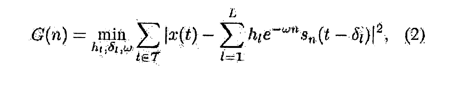
where G(n) is the residual power at the output of the adaptive compensator for the nth signal candidate, w, hl , and δ l are parameters representing the frequency offset, lth complex channel tap, and the corresponding delay. - Different techniques can be used for optimization in (2). The following simplified solution was used in one example:
- Frequency offset correction w is estimated for a single tap channel model (L = 1) by means of direct search in the interval [-wo , wo ] with a conventional correlation based estimation of the channel tap and delay.
- For the given w and L, the channel parameters hl and δ l are estimated by means of conventional iterative correlation based procedure of J iterations with consecutive estimation of each tap.
- For a relatively low sampling frequency of, for example, Frea = 20 MHz, the correlation based channel estimation is supported with additional precise synchronization procedure based on the oversampling of the signals in the training data based with factor Q. For records with higher sampling frequency, e.g. Frea = 200 MHz, the precise synchronization will usually not be necessary.
- Note that the training database of samples corresponding to different terminals may also use a plurality of samples obtained from the same terminal or device operated under significantly different conditions in terms of transmit power, temperature or other parameters. In an experiment the following parameter values were found to work well, T = 2500, Q = 8 and Ω0 = ± 0.4 RAD/S. These values were selected based upon experimental experience. Note that parameter T is the number of samples upon which the test is applied and this linearly relates to computational complexity but also effects algorithm performance, so a value should be selected that provides a reasonable trade off between both. Parameter L is set according to the particular circumstances.
- Thus, in embodiments the actual candidate device is considered to be that which generated signal no (equation 1) in which, from all the samples and comparisons, the value of the residual power G(n) of the signal candidate (the nth signal) which is least for a particular combination of test and training signals is considered to be the candidate device, i.e. the training signal for which the nth residual power is the lowest is considered to be from the same device.
- External changes may affect the signal radiated by a transmitter. These effects can include ageing, transmit power, temperature, supply voltage and others. The algorithm training set can be extended, as described, to include signal variation caused by these external variations. Hence, for each particular transmitter in the training phase a number of different values can be stored and a number of entries made in the database for a range of temperatures, transmit powers, supply voltage and ageing variations. Thus, the transmitter can be recognised under any normal variation of external conditions. Alternatively, if a value can be fixed, it may not be necessary to make an entry for the possibilities. For example, since the transmit power of a UMTS phone can be controlled by the base station, it would not normally be necessary to store values for more than one transmit power.
- If all training signals stored in the database are to be compared with each signal under test, then a large number of comparisons is necessary. In order to reduce this, various means may be used to provide a subset of the training signals against which the test device is measured. One method of doing this is to use the transient signal which is radiated at transmission switch on and switch off. When sampled at relatively low sample frequency, the transient signals still exhibit distinguishing features and these can be used as a first level of categorisation. Low sampling frequency is a low multiple of the data carrying bandwidth. For UMTS the chip rate is 3.84MChips/s so, for example, 20MSamples per second might be considered a low sample rate. As a comparison, Transient techniques typically use 500M-1000MSamples/s. For example, the distinguishing features measured by these initial filtering techniques may be used to determine the manufacturer of a device. If the manufacturer of the device under test is known, then clearly the subset of training signal against which it is to be compared only need be those from devices of that manufacturer.
- Transient techniques are well known in themselves and will not be described further here. Once a subset of data has been determined, then the coherency algorithms described above can be used to do the fine level categorisation using (taps) using the determined subsets.
- The number of multipath simulations achieved through iteration in the
adaptive filter 45 may be set to a predetermined number such a 5 or 10. The algorithm then examines the error signal G(n) for test device 10a upon each iteration of the loop l = 1:L. In practice, when the error signal G(n) stops decreasing, the loop is exited since the minimum value of G(n) has been found. This conditional loop termination optimises execution to the correct number of paths and ensures that only valid paths are removed from the residual signals. - The frequency offset correction is necessary to vary the frequency of the training signal to bring it in line with the frequency of the test signal. Frequency offset correction is performed by modifying the training signal by a number of different frequency offsets and choosing the offset that results in a modified training signal with minimal difference to the test signal.
- If the test signal, in a particular circumstance, is received via four different paths, for example, each representing a different multipath and therefore having different time and phase delays, then in the adaptive filter four sets of delays and taps may be used on four sets of the same training data. These are cross correlated and techniques used to determine if any of them is particularly close to the test signal. The multipath signal is distinguished in difference in time delay and phase delay and these are the parameters that can be simulated in the components of the adaptive filter.
- In embodiments, a technique for performing identification (testing is used) based upon successive subtraction of training signal candidate (modified for frequency, timing offsets and channel effects). To do this, one must be able to construct the reference training database by summing several measurements together after adjusting each for single path phase, frequency offset and timing synchronisation offsets.
- The description and drawings merely illustrate the principles of the invention. It will thus be appreciated that those skilled in the art will be able to devise various arrangements that, although not explicitly described or shown herein, embody the principles of the invention and are included within its spirit and scope. Furthermore, all examples recited herein are principally intended expressly to be only for pedagogical purposes to aid the reader in understanding the principles of the invention and the concepts contributed by the inventor(s) for furthering the art, and are to be construed as being without limitation to such specifically recited examples and conditions. Moreover, all statements herein reciting principles, aspects, and embodiments of the invention, as well as specific examples thereof, are intended to encompass equivalents thereof.
Claims (15)
causing the device to transmit a particular known signal to a receiver and comparing the received signal with a plurality of training signals from a database, the signals being samples of the same known signal transmitted by one or more known devices, and comparing the received signal from the unknown device with the plurality of training signals in order to classify the unknown device as one of the known devices.
means for receiving a signal transmitted from a device under test,
means for receiving signals from a training database and;
an adaptive compensator for comparing the two to determine a residual power for each comparison and for comparing the residual powers to determine the identity of the transmitter.
Priority Applications (1)
| Application Number | Priority Date | Filing Date | Title |
|---|---|---|---|
| EP20100290227 EP2383915B1 (en) | 2010-04-30 | 2010-04-30 | Method and apparatus for identifying a transmitting device |
Applications Claiming Priority (1)
| Application Number | Priority Date | Filing Date | Title |
|---|---|---|---|
| EP20100290227 EP2383915B1 (en) | 2010-04-30 | 2010-04-30 | Method and apparatus for identifying a transmitting device |
Publications (2)
| Publication Number | Publication Date |
|---|---|
| EP2383915A1 true EP2383915A1 (en) | 2011-11-02 |
| EP2383915B1 EP2383915B1 (en) | 2013-04-17 |
Family
ID=42782203
Family Applications (1)
| Application Number | Title | Priority Date | Filing Date |
|---|---|---|---|
| EP20100290227 Not-in-force EP2383915B1 (en) | 2010-04-30 | 2010-04-30 | Method and apparatus for identifying a transmitting device |
Country Status (1)
| Country | Link |
|---|---|
| EP (1) | EP2383915B1 (en) |
Families Citing this family (1)
| Publication number | Priority date | Publication date | Assignee | Title |
|---|---|---|---|---|
| CN111050315B (en) * | 2019-11-27 | 2021-04-13 | 北京邮电大学 | A wireless transmitter identification method based on multi-core dual-channel network |
Citations (3)
| Publication number | Priority date | Publication date | Assignee | Title |
|---|---|---|---|---|
| US20070025265A1 (en) * | 2005-07-22 | 2007-02-01 | Porras Phillip A | Method and apparatus for wireless network security |
| US20080244707A1 (en) * | 2007-03-26 | 2008-10-02 | Bowser Robert A | Wireless transmitter identity validation in a wireless network |
| US20090305665A1 (en) * | 2008-06-04 | 2009-12-10 | Irwin Oliver Kennedy | Method of identifying a transmitting device |
-
2010
- 2010-04-30 EP EP20100290227 patent/EP2383915B1/en not_active Not-in-force
Patent Citations (3)
| Publication number | Priority date | Publication date | Assignee | Title |
|---|---|---|---|---|
| US20070025265A1 (en) * | 2005-07-22 | 2007-02-01 | Porras Phillip A | Method and apparatus for wireless network security |
| US20080244707A1 (en) * | 2007-03-26 | 2008-10-02 | Bowser Robert A | Wireless transmitter identity validation in a wireless network |
| US20090305665A1 (en) * | 2008-06-04 | 2009-12-10 | Irwin Oliver Kennedy | Method of identifying a transmitting device |
Non-Patent Citations (2)
| Title |
|---|
| JACKSON E: "Detecting intrusions at layer one: device fingerprinting for network access authorization", THESIS IOWA STATE UNIVERSITY,, 1 May 2006 (2006-05-01), pages 1 - 51, XP007912242 * |
| KENNEDY I O ET AL: "Passive Steady State RF Fingerprinting: A Cognitive Technique for Scalable Deployment of Co-Channel Femto Cell Underlays", NEW FRONTIERS IN DYNAMIC SPECTRUM ACCESS NETWORKS, 2008. DYSPAN 2008. 3RD IEEE SYMPOSIUM ON, IEEE, PISCATAWAY, NJ, USA, 14 October 2008 (2008-10-14), pages 1 - 12, XP031353285, ISBN: 978-1-4244-2016-2 * |
Also Published As
| Publication number | Publication date |
|---|---|
| EP2383915B1 (en) | 2013-04-17 |
Similar Documents
| Publication | Publication Date | Title |
|---|---|---|
| Merchant et al. | Toward receiver-agnostic RF fingerprint verification | |
| US20100002816A1 (en) | Method and apparatus for multiple signal identification and finding the basis functions of the received signal | |
| JP2008249333A (en) | Direction-of-arrival estimation apparatus and wireless communication apparatus including the same | |
| Talebi et al. | Channel sounding and parameter estimation for a wideband correlation-based MIMO model | |
| KR20180101132A (en) | Method and apparatus for reference signal time difference(rstd) measurment | |
| Edward et al. | Enhancing the capture capabilities of LoRa receivers | |
| KR20050049540A (en) | Method and system for interference assessment and reduction in a wireless communication system | |
| US9014154B2 (en) | Method and apparatus for improved base station cell synchronization in LTE downlink | |
| US9001877B2 (en) | Signal processing for diversity combining radio receiver | |
| EP3503438B1 (en) | Test arrangement and test method | |
| KR20050092127A (en) | Channel estimating method for multi-set of code in slotted cdma system | |
| US8045448B2 (en) | Apparatus and method for detecting packet of zero-padded OFDM signal | |
| EP2383915B1 (en) | Method and apparatus for identifying a transmitting device | |
| Hälsig et al. | Statistical properties and variations of LOS MIMO channels at millimeter wave frequencies | |
| Arsalane et al. | 3GPP channel model emulation with analysis of MIMO‐LTE performances in reverberation chamber | |
| JP7541031B2 (en) | Wireless communication performance measurements that meet gain flatness criteria | |
| US20100014560A1 (en) | Methods of synchronizing with first multipath component in ultra wideband receiver and ultra wideband receivers using the same | |
| KR101126682B1 (en) | Ranging apparatus and method for ranging improving in ODFMA system | |
| Saadane et al. | On the estimation of the degrees of freedom of indoor UWB channel | |
| US20240348318A1 (en) | Method and apparatus for testing disaggregated components of a radio access network | |
| Amatetti et al. | Preamble detection in NB-IoT via satellite: A wavelet based approach | |
| Sung et al. | Interference mitigation based on Bayesian compressive sensing for wireless localization systems in unlicensed band | |
| WO2015066157A1 (en) | Systems and methods for acquiring service using multiple channels | |
| US20260106680A1 (en) | Method for providing a power delay profile for a fading simulator | |
| AU726149B2 (en) | Iterative timing of GSM bursts |
Legal Events
| Date | Code | Title | Description |
|---|---|---|---|
| AK | Designated contracting states |
Kind code of ref document: A1 Designated state(s): AT BE BG CH CY CZ DE DK EE ES FI FR GB GR HR HU IE IS IT LI LT LU LV MC MK MT NL NO PL PT RO SE SI SK SM TR |
|
| AX | Request for extension of the european patent |
Extension state: AL BA ME RS |
|
| PUAI | Public reference made under article 153(3) epc to a published international application that has entered the european phase |
Free format text: ORIGINAL CODE: 0009012 |
|
| RAP1 | Party data changed (applicant data changed or rights of an application transferred) |
Owner name: ALCATEL LUCENT |
|
| 17P | Request for examination filed |
Effective date: 20120502 |
|
| GRAP | Despatch of communication of intention to grant a patent |
Free format text: ORIGINAL CODE: EPIDOSNIGR1 |
|
| GRAS | Grant fee paid |
Free format text: ORIGINAL CODE: EPIDOSNIGR3 |
|
| GRAA | (expected) grant |
Free format text: ORIGINAL CODE: 0009210 |
|
| AK | Designated contracting states |
Kind code of ref document: B1 Designated state(s): AT BE BG CH CY CZ DE DK EE ES FI FR GB GR HR HU IE IS IT LI LT LU LV MC MK MT NL NO PL PT RO SE SI SK SM TR |
|
| REG | Reference to a national code |
Ref country code: GB Ref legal event code: FG4D |
|
| REG | Reference to a national code |
Ref country code: CH Ref legal event code: EP |
|
| REG | Reference to a national code |
Ref country code: IE Ref legal event code: FG4D |
|
| REG | Reference to a national code |
Ref country code: AT Ref legal event code: REF Ref document number: 607851 Country of ref document: AT Kind code of ref document: T Effective date: 20130515 |
|
| REG | Reference to a national code |
Ref country code: DE Ref legal event code: R096 Ref document number: 602010006260 Country of ref document: DE Effective date: 20130613 |
|
| REG | Reference to a national code |
Ref country code: AT Ref legal event code: MK05 Ref document number: 607851 Country of ref document: AT Kind code of ref document: T Effective date: 20130417 |
|
| REG | Reference to a national code |
Ref country code: LT Ref legal event code: MG4D |
|
| 111Z | Information provided on other rights and legal means of execution |
Free format text: AT BE BG CH CY CZ DE DK EE ES FI FR GB GR HR HU IE IS IT LI LT LU LV MC MK MT NL NO PL PT RO SE SI SK SM TR Effective date: 20130410 |
|
| REG | Reference to a national code |
Ref country code: NL Ref legal event code: VDEP Effective date: 20130417 |
|
| PG25 | Lapsed in a contracting state [announced via postgrant information from national office to epo] |
Ref country code: BE Free format text: LAPSE BECAUSE OF FAILURE TO SUBMIT A TRANSLATION OF THE DESCRIPTION OR TO PAY THE FEE WITHIN THE PRESCRIBED TIME-LIMIT Effective date: 20130417 Ref country code: ES Free format text: LAPSE BECAUSE OF FAILURE TO SUBMIT A TRANSLATION OF THE DESCRIPTION OR TO PAY THE FEE WITHIN THE PRESCRIBED TIME-LIMIT Effective date: 20130728 Ref country code: PT Free format text: LAPSE BECAUSE OF FAILURE TO SUBMIT A TRANSLATION OF THE DESCRIPTION OR TO PAY THE FEE WITHIN THE PRESCRIBED TIME-LIMIT Effective date: 20130819 Ref country code: SE Free format text: LAPSE BECAUSE OF FAILURE TO SUBMIT A TRANSLATION OF THE DESCRIPTION OR TO PAY THE FEE WITHIN THE PRESCRIBED TIME-LIMIT Effective date: 20130417 Ref country code: LT Free format text: LAPSE BECAUSE OF FAILURE TO SUBMIT A TRANSLATION OF THE DESCRIPTION OR TO PAY THE FEE WITHIN THE PRESCRIBED TIME-LIMIT Effective date: 20130417 Ref country code: FI Free format text: LAPSE BECAUSE OF FAILURE TO SUBMIT A TRANSLATION OF THE DESCRIPTION OR TO PAY THE FEE WITHIN THE PRESCRIBED TIME-LIMIT Effective date: 20130417 Ref country code: NO Free format text: LAPSE BECAUSE OF FAILURE TO SUBMIT A TRANSLATION OF THE DESCRIPTION OR TO PAY THE FEE WITHIN THE PRESCRIBED TIME-LIMIT Effective date: 20130717 Ref country code: GR Free format text: LAPSE BECAUSE OF FAILURE TO SUBMIT A TRANSLATION OF THE DESCRIPTION OR TO PAY THE FEE WITHIN THE PRESCRIBED TIME-LIMIT Effective date: 20130718 Ref country code: IS Free format text: LAPSE BECAUSE OF FAILURE TO SUBMIT A TRANSLATION OF THE DESCRIPTION OR TO PAY THE FEE WITHIN THE PRESCRIBED TIME-LIMIT Effective date: 20130817 Ref country code: AT Free format text: LAPSE BECAUSE OF FAILURE TO SUBMIT A TRANSLATION OF THE DESCRIPTION OR TO PAY THE FEE WITHIN THE PRESCRIBED TIME-LIMIT Effective date: 20130417 Ref country code: SI Free format text: LAPSE BECAUSE OF FAILURE TO SUBMIT A TRANSLATION OF THE DESCRIPTION OR TO PAY THE FEE WITHIN THE PRESCRIBED TIME-LIMIT Effective date: 20130417 |
|
| PG25 | Lapsed in a contracting state [announced via postgrant information from national office to epo] |
Ref country code: BG Free format text: LAPSE BECAUSE OF FAILURE TO SUBMIT A TRANSLATION OF THE DESCRIPTION OR TO PAY THE FEE WITHIN THE PRESCRIBED TIME-LIMIT Effective date: 20130717 Ref country code: CY Free format text: LAPSE BECAUSE OF FAILURE TO SUBMIT A TRANSLATION OF THE DESCRIPTION OR TO PAY THE FEE WITHIN THE PRESCRIBED TIME-LIMIT Effective date: 20130417 Ref country code: HR Free format text: LAPSE BECAUSE OF FAILURE TO SUBMIT A TRANSLATION OF THE DESCRIPTION OR TO PAY THE FEE WITHIN THE PRESCRIBED TIME-LIMIT Effective date: 20130417 Ref country code: LV Free format text: LAPSE BECAUSE OF FAILURE TO SUBMIT A TRANSLATION OF THE DESCRIPTION OR TO PAY THE FEE WITHIN THE PRESCRIBED TIME-LIMIT Effective date: 20130417 Ref country code: PL Free format text: LAPSE BECAUSE OF FAILURE TO SUBMIT A TRANSLATION OF THE DESCRIPTION OR TO PAY THE FEE WITHIN THE PRESCRIBED TIME-LIMIT Effective date: 20130417 |
|
| REG | Reference to a national code |
Ref country code: IE Ref legal event code: MM4A |
|
| PG25 | Lapsed in a contracting state [announced via postgrant information from national office to epo] |
Ref country code: SK Free format text: LAPSE BECAUSE OF FAILURE TO SUBMIT A TRANSLATION OF THE DESCRIPTION OR TO PAY THE FEE WITHIN THE PRESCRIBED TIME-LIMIT Effective date: 20130417 Ref country code: MC Free format text: LAPSE BECAUSE OF FAILURE TO SUBMIT A TRANSLATION OF THE DESCRIPTION OR TO PAY THE FEE WITHIN THE PRESCRIBED TIME-LIMIT Effective date: 20130417 Ref country code: CZ Free format text: LAPSE BECAUSE OF FAILURE TO SUBMIT A TRANSLATION OF THE DESCRIPTION OR TO PAY THE FEE WITHIN THE PRESCRIBED TIME-LIMIT Effective date: 20130417 Ref country code: EE Free format text: LAPSE BECAUSE OF FAILURE TO SUBMIT A TRANSLATION OF THE DESCRIPTION OR TO PAY THE FEE WITHIN THE PRESCRIBED TIME-LIMIT Effective date: 20130417 Ref country code: DK Free format text: LAPSE BECAUSE OF FAILURE TO SUBMIT A TRANSLATION OF THE DESCRIPTION OR TO PAY THE FEE WITHIN THE PRESCRIBED TIME-LIMIT Effective date: 20130417 |
|
| PLBE | No opposition filed within time limit |
Free format text: ORIGINAL CODE: 0009261 |
|
| STAA | Information on the status of an ep patent application or granted ep patent |
Free format text: STATUS: NO OPPOSITION FILED WITHIN TIME LIMIT |
|
| PG25 | Lapsed in a contracting state [announced via postgrant information from national office to epo] |
Ref country code: NL Free format text: LAPSE BECAUSE OF FAILURE TO SUBMIT A TRANSLATION OF THE DESCRIPTION OR TO PAY THE FEE WITHIN THE PRESCRIBED TIME-LIMIT Effective date: 20130417 Ref country code: IT Free format text: LAPSE BECAUSE OF FAILURE TO SUBMIT A TRANSLATION OF THE DESCRIPTION OR TO PAY THE FEE WITHIN THE PRESCRIBED TIME-LIMIT Effective date: 20130417 Ref country code: RO Free format text: LAPSE BECAUSE OF FAILURE TO SUBMIT A TRANSLATION OF THE DESCRIPTION OR TO PAY THE FEE WITHIN THE PRESCRIBED TIME-LIMIT Effective date: 20130417 |
|
| 26N | No opposition filed |
Effective date: 20140120 |
|
| PG25 | Lapsed in a contracting state [announced via postgrant information from national office to epo] |
Ref country code: IE Free format text: LAPSE BECAUSE OF NON-PAYMENT OF DUE FEES Effective date: 20130430 |
|
| REG | Reference to a national code |
Ref country code: DE Ref legal event code: R097 Ref document number: 602010006260 Country of ref document: DE Effective date: 20140120 |
|
| REG | Reference to a national code |
Ref country code: CH Ref legal event code: PCOW Free format text: NEW ADDRESS: 148/152 ROUTE DE LA REINE, 92100 BOULOGNE-BILLANCOURT (FR) |
|
| REG | Reference to a national code |
Ref country code: CH Ref legal event code: PL |
|
| PG25 | Lapsed in a contracting state [announced via postgrant information from national office to epo] |
Ref country code: LI Free format text: LAPSE BECAUSE OF NON-PAYMENT OF DUE FEES Effective date: 20140430 Ref country code: CH Free format text: LAPSE BECAUSE OF NON-PAYMENT OF DUE FEES Effective date: 20140430 |
|
| PG25 | Lapsed in a contracting state [announced via postgrant information from national office to epo] |
Ref country code: MT Free format text: LAPSE BECAUSE OF FAILURE TO SUBMIT A TRANSLATION OF THE DESCRIPTION OR TO PAY THE FEE WITHIN THE PRESCRIBED TIME-LIMIT Effective date: 20130417 |
|
| REG | Reference to a national code |
Ref country code: FR Ref legal event code: PLFP Year of fee payment: 6 |
|
| PG25 | Lapsed in a contracting state [announced via postgrant information from national office to epo] |
Ref country code: SM Free format text: LAPSE BECAUSE OF FAILURE TO SUBMIT A TRANSLATION OF THE DESCRIPTION OR TO PAY THE FEE WITHIN THE PRESCRIBED TIME-LIMIT Effective date: 20130417 |
|
| PG25 | Lapsed in a contracting state [announced via postgrant information from national office to epo] |
Ref country code: TR Free format text: LAPSE BECAUSE OF FAILURE TO SUBMIT A TRANSLATION OF THE DESCRIPTION OR TO PAY THE FEE WITHIN THE PRESCRIBED TIME-LIMIT Effective date: 20130417 |
|
| PG25 | Lapsed in a contracting state [announced via postgrant information from national office to epo] |
Ref country code: MK Free format text: LAPSE BECAUSE OF FAILURE TO SUBMIT A TRANSLATION OF THE DESCRIPTION OR TO PAY THE FEE WITHIN THE PRESCRIBED TIME-LIMIT Effective date: 20130417 Ref country code: HU Free format text: LAPSE BECAUSE OF FAILURE TO SUBMIT A TRANSLATION OF THE DESCRIPTION OR TO PAY THE FEE WITHIN THE PRESCRIBED TIME-LIMIT; INVALID AB INITIO Effective date: 20100430 Ref country code: LU Free format text: LAPSE BECAUSE OF NON-PAYMENT OF DUE FEES Effective date: 20130430 |
|
| REG | Reference to a national code |
Ref country code: FR Ref legal event code: PLFP Year of fee payment: 7 |
|
| REG | Reference to a national code |
Ref country code: FR Ref legal event code: PLFP Year of fee payment: 8 |
|
| REG | Reference to a national code |
Ref country code: FR Ref legal event code: PLFP Year of fee payment: 9 |
|
| PGFP | Annual fee paid to national office [announced via postgrant information from national office to epo] |
Ref country code: DE Payment date: 20180420 Year of fee payment: 9 |
|
| PGFP | Annual fee paid to national office [announced via postgrant information from national office to epo] |
Ref country code: FR Payment date: 20180420 Year of fee payment: 9 |
|
| PGFP | Annual fee paid to national office [announced via postgrant information from national office to epo] |
Ref country code: GB Payment date: 20180418 Year of fee payment: 9 |
|
| REG | Reference to a national code |
Ref country code: DE Ref legal event code: R119 Ref document number: 602010006260 Country of ref document: DE |
|
| GBPC | Gb: european patent ceased through non-payment of renewal fee |
Effective date: 20190430 |
|
| PG25 | Lapsed in a contracting state [announced via postgrant information from national office to epo] |
Ref country code: DE Free format text: LAPSE BECAUSE OF NON-PAYMENT OF DUE FEES Effective date: 20191101 Ref country code: GB Free format text: LAPSE BECAUSE OF NON-PAYMENT OF DUE FEES Effective date: 20190430 |
|
| PG25 | Lapsed in a contracting state [announced via postgrant information from national office to epo] |
Ref country code: FR Free format text: LAPSE BECAUSE OF NON-PAYMENT OF DUE FEES Effective date: 20190430 |