EP2383896A1 - Methods and devices for detecting electromagnetic interference on data transmission lines - Google Patents
Methods and devices for detecting electromagnetic interference on data transmission lines Download PDFInfo
- Publication number
- EP2383896A1 EP2383896A1 EP10305467A EP10305467A EP2383896A1 EP 2383896 A1 EP2383896 A1 EP 2383896A1 EP 10305467 A EP10305467 A EP 10305467A EP 10305467 A EP10305467 A EP 10305467A EP 2383896 A1 EP2383896 A1 EP 2383896A1
- Authority
- EP
- European Patent Office
- Prior art keywords
- power supply
- supply unit
- frequency
- determining
- power spectrum
- Prior art date
- Legal status (The legal status is an assumption and is not a legal conclusion. Google has not performed a legal analysis and makes no representation as to the accuracy of the status listed.)
- Granted
Links
- 238000000034 method Methods 0.000 title claims abstract description 31
- 230000005540 biological transmission Effects 0.000 title claims abstract description 18
- 238000001228 spectrum Methods 0.000 claims abstract description 48
- 238000004891 communication Methods 0.000 claims abstract description 5
- 238000005311 autocorrelation function Methods 0.000 claims description 7
- 238000005259 measurement Methods 0.000 claims description 5
- 238000004364 calculation method Methods 0.000 claims description 2
- 238000001514 detection method Methods 0.000 abstract description 2
- 230000003252 repetitive effect Effects 0.000 abstract description 2
- 239000011159 matrix material Substances 0.000 description 5
- 239000000969 carrier Substances 0.000 description 4
- 230000001419 dependent effect Effects 0.000 description 4
- 230000003116 impacting effect Effects 0.000 description 3
- 230000001186 cumulative effect Effects 0.000 description 1
- 230000002452 interceptive effect Effects 0.000 description 1
- 238000010606 normalization Methods 0.000 description 1
- 230000000737 periodic effect Effects 0.000 description 1
- 230000003595 spectral effect Effects 0.000 description 1
- 238000011179 visual inspection Methods 0.000 description 1
Images


Classifications
-
- H—ELECTRICITY
- H04—ELECTRIC COMMUNICATION TECHNIQUE
- H04B—TRANSMISSION
- H04B3/00—Line transmission systems
- H04B3/02—Details
- H04B3/46—Monitoring; Testing
-
- H—ELECTRICITY
- H04—ELECTRIC COMMUNICATION TECHNIQUE
- H04B—TRANSMISSION
- H04B3/00—Line transmission systems
- H04B3/02—Details
Definitions
- the present invention relates to the field of methods and devices for resolving problems related to the impact of electromagnetic interference on data transmission lines, as for instance DSL lines.
- Power supply units (PSU) of many household appliances comprise switching converters, working at switching frequencies laying within the range of frequencies associated with DSL signals.
- switching converters are known to be a common source of electromagnetic interference (EMI) for in-house cabling networks (usually untwisted, low category cables) that carry for instance DSL signals.
- EMI electromagnetic interference
- the DSL performance can degrade substantially because of such interference.
- a method for remotely detecting electromagnetic interference on a data transmission line of a communication network, in particular for electromagnetic interference caused by a power supply unit located at a client site, the power supply unit comprising a switching converter (e.g. a DC/DC or AC/DC convertor) having a switching frequency, comprising
- a switching converter e.g. a DC/DC or AC/DC convertor
- the method further comprises determining a YIN estimator, the YIN estimator being defined as d ⁇ ⁇ f ⁇ ⁇ 1 , if ⁇ f ⁇ 0 d ⁇ 1 ⁇ f ⁇ j ⁇ 1 ⁇ f d j , otherwise with d ⁇ f ⁇ ⁇ j ⁇ 1 N x j ⁇ x j ⁇ ⁇ f 2 wherein ⁇ f is a frequency difference value, x j is the power spectrum value of the signal for discrete signal frequencies j, and N is the number of discrete signal frequencies within the predetermined width of the power spectrum of the signal;
- said minimum value is the minimum value different from the value corresponding to frequency 0.
- determining periodicities in the power spectrum comprises;
- said maximum is the maximum different from the value corresponding to frequency 0.
- determining periodicities in the power spectrum comprises;
- the largest peak value is the largest peak value different from the value corresponding to frequency 0.
- determining periodicities in the power spectrum comprises
- the predetermined frequency range comprises the whole power spectrum of the noise signal.
- the method further comprises detecting which frequency range of signals on the line is impacted by the power supply unit, by performing any of the methods described before a plurality of times for a plurality of different frequency ranges of a predetermined width, the predetermined width being smaller than the width of the whole noise spectrum.
- the method comprises detecting which frequency range of signals on the line is impacted by the power supply unit, comprising
- the method comprises detecting which frequency range of signals on the line is impacted by the power supply unit, comprising
- the method comprises looking up the determined switching frequency in a predetermined information list, the list comprising information relating to predetermined types of power supply units and their associated switching frequencies, thereby identifying the type of the power supply unit.
- the method comprises forwarding information regarding the type of power supply unit by the remote computing means to at least one client device on the client site.
- the method comprises storing the switching frequencies for use in network management purposes.
- a remote computing means for detecting electromagnetic interference on a data transmission line of a communication network, in particular for electromagnetic interference caused by a power supply unit located at a client site, the power supply unit comprising a switching converter having a predetermined switching frequency, comprising
- the remote computer means comprises a means for forwarding information regarding the type of power supply unit to at least one client device on the client site.
- Figure 1 which represents a noise power spectrum graph as a function of frequency, more specifically a QLN graph
- the main characteristic of PSU related interference is the periodicity in the affected frequencies. This can be explained by the fact that a PSU of switching type typically generates a square current waveform.
- the spectral content of the radiated interference is made of a fundamental frequency corresponding to the PSU switching frequency, and all of its harmonics.
- the fundamental frequency may also not be visible, for instance because of the PSU internal filter, or because the power level of the interference is smaller than the crosstalk level or the modem noise floor, being the level below which the modem cannot detect any signal (noise).
- the usual signature of a PSU impacting a DSL line is typically thus a sequence of harmonics, regularly spaced by a frequency interval equal to the PSU switching frequency.
- an algorithm is disclosed which is based on a list of perturbed carriers:
- a distance matrix is computed, i.e. a matrix that contains the differences of frequencies between all pairs of Radio Frequency Interferences (RFIs).
- RFIs Radio Frequency Interferences
- 13 RFIs are detected.
- a 13x13 matrix is generated comprising the absolute differences between the frequencies.
- Table 1 Distance matrix based on detected RFIs.
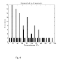
- a histogram is filled with the data comprised in the distance matrix (illustrated in Fig. 4 ).
- the maximum filling of the histogram occurs for a frequency distance of 16, and corresponds to the fundamental frequency of all the harmonics detected in the power spectrum, here the QLN.
- the presence of a repetitive pattern in the QLN can be detected and this corresponds or can be associated with the switching frequency of the PSU.
- the power cepstrum of a signal is the square of the Fourier transform of the logarithm of the squared magnitude of the Fourier transform; Cepstrum x ⁇ FT ⁇ log FT x 2 2
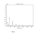
- Finding the maximum of the cepstrum is equivalent to finding the fundamental frequency of the signal. This is illustrated at the Figure 2 , which is the power cepstrum of the QLN showed at Figure 1 . As one can see, there is a peak at a frequency value of 16, which indeed corresponds to the fundamental frequency of the PSU impacting the DSL line.
- the second equation is a difference function between the signal and the same signal shifted by a certain frequency difference ( ⁇ f).
- the first equation is the estimator function d' ( ⁇ f), and is a normalization by the cumulative mean of the difference function.
- Finding the minimum of this estimator function allows determining a fundamental frequency of the input signal, which can be associated with the switching frequency of the PSU.
- a fifth embodiment provides a modified version of the YIN estimator.
- the difference function is calculated along a sliding window.
- the method comprises in choosing a window, the width of which is smaller than the signal width, applying the YIN estimator inside this window.
- the window is then shifted and the YIN estimator is computed in the shifted window.
- the window is shifted again etc., until the window reaches the end of the noise signal.
- This allows applying the algorithm for different starting points f 0 , in a certain view as if the computation window slides over the input signal from left to right.
- the sliding window approach as described above can also be applied in the content of the autocorrelation embodiment or the cepstrum embodiment.
- the window preferably comprises a sufficient number of the observed signal periods.
- a signal that varies slowly (long periodicity) would need a relatively large window to be observed.
- the method of a sixth embodiment makes the window width dependent of the frequency difference ⁇ f.
- the output of methods according to the fifth and sixth embodiment is a 2D space. Finding a minimum of this space allows determining the fundamental frequency of the disturbing signal, as well as localizing the impacted frequency range. This is illustrated for instance in Figure 3 .
- the projection of the minimum area on the frequency axis gives the fundamental frequency (PSU switching frequency).
- the projection on the horizontal axis allows determining the portion of the power spectrum that is impacted.
- electromagnetic interference can proactively be detected and analysed.
- a PSU unit which is causing interference can be identified by looking up which PSU unit is present at the client site based on the determined PSU switching frequency and a list of switching frequencies of commercially available PSU's.
- the list can for instance comprise information relating to the PSU of the DSL modem itself (or IPTV set-top box usually close to the DSL modem).
- This information can then be provided to a client device at the client site. Based thereon the client may recognize a bad cable or may for instance displace the respective PSU to another location.
- the interference frequency and/or associated PSU's can also be stored at a server on a network operator side for network management purposes.
- the information can then be forwarded at appropriate times, to a client.
Landscapes
- Engineering & Computer Science (AREA)
- Computer Networks & Wireless Communication (AREA)
- Signal Processing (AREA)
- Monitoring And Testing Of Transmission In General (AREA)
- Noise Elimination (AREA)
- Testing Electric Properties And Detecting Electric Faults (AREA)
- Cable Transmission Systems, Equalization Of Radio And Reduction Of Echo (AREA)
Abstract
- measuring at a client site a noise power spectrum on said data transmission line as a function of frequency, for a predetermined frequency range, said noise being present when said data transmission line is not carrying a data signal;
- forwarding said measured noise power spectrum to a remote computing means at a network operator's site;
- determining periodicities in said measured power spectrum by said remote computing means;
- determining the switching frequency of said power supply unit by said remote computing means, based on periodicities in said power spectrum; and remote computing means.
The method is based on REIN: Repetitive Electrical Impulse Noise detection.
Description
- The present invention relates to the field of methods and devices for resolving problems related to the impact of electromagnetic interference on data transmission lines, as for instance DSL lines.
- Power supply units (PSU) of many household appliances comprise switching converters, working at switching frequencies laying within the range of frequencies associated with DSL signals. Such switching converters are known to be a common source of electromagnetic interference (EMI) for in-house cabling networks (usually untwisted, low category cables) that carry for instance DSL signals. The DSL performance can degrade substantially because of such interference.
- Today, the detection of Power Supply Unit related problems impacting a DSL line can only be performed by means of visual inspection by an expert of carrier data measured by the modem.
- As this analysis can only be performed by an expert, it can only be performed after a customer complaint (reactive way), by the
level - It is an object of the present invention to provide methods and devices for detecting electromagnetic interference on data transmission lines which solves at least one of the above problems.
- This is achieved by the features of
claim 1 and 11. - According to a first aspect of the present invention a method is disclosed for remotely detecting electromagnetic interference on a data transmission line of a communication network, in particular for electromagnetic interference caused by a power supply unit located at a client site, the power supply unit comprising a switching converter (e.g. a DC/DC or AC/DC convertor) having a switching frequency, comprising
- measuring at a client site a power spectrum of a noise signal on the data transmission line as a function of frequency, for a predetermined frequency range, the noise being present when the data transmission line is not carrying a data signal;
- forwarding the measured noise power spectrum to a remote computing means at a network operator's site;
- determining periodicities in the measured power spectrum by the remote computing means;
- determining the switching frequency of the power supply unit by the remote computing means, based on periodicities in the power spectrum.
- According to embodiments of the first aspect of the present invention, the method further comprises determining a YIN estimator, the YIN estimator being defined as


wherein □f is a frequency difference value, xj is the power spectrum value of the signal for discrete signal frequencies j, and N is the number of discrete signal frequencies within the predetermined width of the power spectrum of the signal; - determining the minimum value for the YIN estimator;
- associating the minimum value of the YIN estimator with the switching frequency of the power supply unit.
- Preferably, said minimum value is the minimum value different from the value corresponding to
frequency 0. - According to embodiments of the first aspect of the present invention, determining periodicities in the power spectrum comprises;
- determining an autocorrelation function for the measured power spectrum;
- determining the maximum of the autocorrelation function;
- associating the switching frequency of the power supply unit with the maximum of the autocorrelation function.
- Preferably said maximum is the maximum different from the value corresponding to
frequency 0. - According to embodiments of the first aspect of the present invention, determining periodicities in the power spectrum comprises;
- determining a cepstrum of the noise signal, the cepstrum being the square of the Fourier transform of the 10-based logarithm of the squared magnitude of the fourier transform of the noise signal;
- derive a frequency value corresponding to the largest peak value for the cepstrum;
- associating the switching frequency of the power supply unit with the frequency value.
- Preferably the largest peak value is the largest peak value different from the value corresponding to
frequency 0. - According to embodiments of the first aspect of the present invention, determining periodicities in the power spectrum comprises
- a. detecting a set of peak values and associated peak frequencies in the power spectrum;
- b. determining a set of difference values, the values consisting of the differences between each pair of frequencies of the set of peak frequencies;
- c. counting the number of occurrences of similar difference values for the set of difference values;
- d. associating the switching frequency of the power supply unit with the difference value which has the largest number of occurrences.
- According to embodiments of the first aspect of the present invention, the predetermined frequency range comprises the whole power spectrum of the noise signal.
- According to embodiments of the first aspect of the present invention, the method further comprises detecting which frequency range of signals on the line is impacted by the power supply unit, by performing any of the methods described before a plurality of times for a plurality of different frequency ranges of a predetermined width, the predetermined width being smaller than the width of the whole noise spectrum.
- According to embodiments of the first aspect of the present invention, the method comprises detecting which frequency range of signals on the line is impacted by the power supply unit, comprising
- determining a two-dimensional Yin estimator defined as;


wherein □f is a frequency difference value, f0 a start frequency, xj is the power spectrum value of the signal for discrete signal frequency j, and W is the width of the part of the power spectrum for which the YIN estimator is estimated, this width being smaller than the whole power spectrum of the noise signal; - determining a two-dimensional minimum value area of the two-dimensional estimator;
- associating the two-dimensional minimum value area with the switching frequency of the power supply unit and with the frequency range which is impacted by the power supply unit.
- According to embodiments of the first aspect of the present invention, the method comprises detecting which frequency range of signals on the line is impacted by the power supply unit, comprising
- determining a two-dimensional Yin estimator defined as;


wherein □f is a frequency difference value, f0 a start frequency, xj is the power spectrum value of the signal for discrete signal frequencies j, and k is a predetermined multiplication factor; - determining a two-dimensional minimum value area of the two-dimensional estimator;
- associating the two-dimensional minimum value area with the switching frequency of the power supply unit and with the a frequency range which is impacted by the power supply unit.
- According to embodiments of the first aspect of the present invention, the method comprises looking up the determined switching frequency in a predetermined information list, the list comprising information relating to predetermined types of power supply units and their associated switching frequencies, thereby identifying the type of the power supply unit.
- According to embodiments of the first aspect of the present invention, the method comprises forwarding information regarding the type of power supply unit by the remote computing means to at least one client device on the client site.
- According to embodiments of the first aspect of the present invention, the method comprises storing the switching frequencies for use in network management purposes.
- According to a second aspect of the present invention a remote computing means is disclosed for detecting electromagnetic interference on a data transmission line of a communication network, in particular for electromagnetic interference caused by a power supply unit located at a client site, the power supply unit comprising a switching converter having a predetermined switching frequency, comprising
- a reception means for receiving power spectrum measurements for a noise signal on a transmission line as a function of frequency for a predetermined frequency range from a client site, the noise signal being present when the transmission line is not carrying a data signal;
- a calculation means for determining periodicities in the power spectrum measurements and for determining the switching frequency of the power supply unit, based on periodicities in the power spectrum.
- According to embodiments of the second aspect of the present invention the remote computing means further comprises
- a means for looking up the determined switching frequency in a predetermined information list, the list comprising information relating to predetermined types of power supply units and their associated switching frequencies, thereby identifying the type of the power - supply unit.
- According to embodiments of the second aspect of the present invention the remote computer means comprises a means for forwarding information regarding the type of power supply unit to at least one client device on the client site. Further aspects of the present invention are described by the dependent claims. The features from the dependent claims, features of any of the independent claims and any features of other dependent claims may be combined as considered appropriate to the person of ordinary skill, and not only in the particular combinations as defined by the claims.
- The accompanying drawings are used to illustrate embodiments of the present invention.
-
Fig. 1 is a graph illustrating a case wherein the interference of the power supply unit can be recognised visually in the power spectrum represented by the Quite-Line Noise (QLN). -
Fig. 2 shows a QLN power cepstrum graph. -
Fig. 3 illustrates the use of a two-dimensional estimator according to embodiments of the present invention. -
Fig. 4 illustrates a histogram used according to embodiment of the present invention. - The above and other advantageous features and objects of the invention will become more apparent and the invention will be better understood from the following detailed description when read in conjunction with the respective drawings.
- As illustrated in
Figure 1 , which represents a noise power spectrum graph as a function of frequency, more specifically a QLN graph, the main characteristic of PSU related interference is the periodicity in the affected frequencies. This can be explained by the fact that a PSU of switching type typically generates a square current waveform. The spectral content of the radiated interference is made of a fundamental frequency corresponding to the PSU switching frequency, and all of its harmonics. - Note that usually not all the harmonics are visible and that the fundamental frequency may also not be visible, for instance because of the PSU internal filter, or because the power level of the interference is smaller than the crosstalk level or the modem noise floor, being the level below which the modem cannot detect any signal (noise).
- The usual signature of a PSU impacting a DSL line is typically thus a sequence of harmonics, regularly spaced by a frequency interval equal to the PSU switching frequency.
- In embodiments of the present invention methods and devices are disclosed that can automatically detect this interference and that can deduce the presence of an interfering PSU.
- According to a first embodiment of the present invention, an algorithm is disclosed which is based on a list of perturbed carriers:
- This algorithm comprises retrieving a list of the impacted carriers, corresponding to the peaks in a QLN graph.
- This list for the measurements illustrated in
figure 1 is for instance;
57,83,100,116,132,149,165,182,197,214,231,235,247 - Nearly all the peaks are separated by a gap of around 16 tones (strictly the gap can be 15, 16 or 17 due to the frequency resolution of exactly 1 carrier).
- This can be automatically detected, for instance by computing the carrier gaps between all the detected peaks and taking the most frequent value, preferably within a range of +1/-1 carrier.
- First, a distance matrix is computed, i.e. a matrix that contains the differences of frequencies between all pairs of Radio Frequency Interferences (RFIs). In this example, 13 RFIs are detected. A 13x13 matrix is generated comprising the absolute differences between the frequencies.
Table 1: Distance matrix based on detected RFIs. 57 83 100 116 132 149 165 182 197 214 231 235 247 57 0 26 43 59 75 92 108 125 140 157 174 178 190 83 26 0 17 33 49 66 82 99 114 131 148 152 164 100 43 17 0 16 32 49 65 82 97 114 131 135 147 116 59 33 16 0 16 33 49 66 81 98 115 119 131 132 75 49 32 16 0 17 33 50 65 82 99 103 115 149 92 66 49 33 17 0 16 33 48 65 82 86 98 165 108 82 65 49 33 16 0 17 32 49 66 70 82 182 125 99 82 66 50 33 17 0 15 32 49 53 65 197 140 114 97 81 65 48 32 15 0 17 34 38 50 214 157 131 114 98 82 65 49 32 17 0 17 21 33 231 174 148 131 115 99 82 66 49 34 17 0 4 16 235 178 152 135 119 103 86 70 53 38 21 4 0 12 247 190 164 147 131 115 98 82 65 50 33 16 12 0 - Then a histogram is filled with the data comprised in the distance matrix (illustrated in
Fig. 4 ). The maximum filling of the histogram occurs for a frequency distance of 16, and corresponds to the fundamental frequency of all the harmonics detected in the power spectrum, here the QLN. - In this example, it can be concluded that the DSL line is impacted by a PSU whose switching frequency is equal to 16 DSL carriers (16*4.3125kHz=69kHz); 4,3125 kHz being the frequency spacing between 2 adjacent DSL carriers.
- According to a second embodiment of the present invention, use is made of the autocorrelation function of the power spectrum. This autocorrelation is defined by the formula: w

- By finding the maximum of the autocorrelation of the QLN, the presence of a repetitive pattern in the QLN can be detected and this corresponds or can be associated with the switching frequency of the PSU.
- According to a third of embodiment, use is made of the power cepstrum of the noise signal. By definition, the power cepstrum of a signal is the square of the Fourier transform of the logarithm of the squared magnitude of the Fourier transform;

- As the QLN is already the logarithm of the square magnitude of the Fourier transform on the noise, the cepstrum of the noise on a DSL line is given by the square of the Fourier transform on the QLN.

- Finding the maximum of the cepstrum is equivalent to finding the fundamental frequency of the signal. This is illustrated at the
Figure 2 , which is the power cepstrum of the QLN showed atFigure 1 . As one can see, there is a peak at a frequency value of 16, which indeed corresponds to the fundamental frequency of the PSU impacting the DSL line. - According to a fourth embodiment, use can be made of a YIN estimator, defined by the following equations:


- The second equation is a difference function between the signal and the same signal shifted by a certain frequency difference (Δf).
- The first equation is the estimator function d' (Δf), and is a normalization by the cumulative mean of the difference function.
- Finding the minimum of this estimator function allows determining a fundamental frequency of the input signal, which can be associated with the switching frequency of the PSU.
- The main drawback of these embodiments, (as well as the embodiments which make use of the autocorrelation or cepstrum), is that they work well only if a substantial part of the input signal is impacted by the harmonics of the periodic noise. They do typically not allow localizing which frequency range on the signal is impacted by the electromagnetic interference.
- To overcome this limitation, a fifth embodiment provides a modified version of the YIN estimator. Hereby, the difference function is calculated along a sliding window. The method comprises in choosing a window, the width of which is smaller than the signal width, applying the YIN estimator inside this window. The window is then shifted and the YIN estimator is computed in the shifted window. Then the window is shifted again etc., until the window reaches the end of the noise signal. This allows applying the algorithm for different starting points f0, in a certain view as if the computation window slides over the input signal from left to right. The sliding window approach as described above can also be applied in the content of the autocorrelation embodiment or the cepstrum embodiment.
- Mathematically, it can be formulated as


- In this algorithm based on a "sliding window", the window preferably comprises a sufficient number of the observed signal periods. A signal that varies slowly (long periodicity) would need a relatively large window to be observed.
- To overcome this possible limitation, the method of a sixth embodiment makes the window width dependent of the frequency difference Δf. This can mathematically be expressed for instance by:


- The output of methods according to the fifth and sixth embodiment is a 2D space. Finding a minimum of this space allows determining the fundamental frequency of the disturbing signal, as well as localizing the impacted frequency range. This is illustrated for instance in
Figure 3 . - The projection of the minimum area on the frequency axis gives the fundamental frequency (PSU switching frequency). The projection on the horizontal axis allows determining the portion of the power spectrum that is impacted.
- It is an advantage of aspects of the present invention that electromagnetic interference can proactively be detected and analysed.
- It is an advantage of aspects of the present invention that a PSU unit which is causing interference can be identified by looking up which PSU unit is present at the client site based on the determined PSU switching frequency and a list of switching frequencies of commercially available PSU's.
- The list can for instance comprise information relating to the PSU of the DSL modem itself (or IPTV set-top box usually close to the DSL modem).
- This information can then be provided to a client device at the client site. Based thereon the client may recognize a bad cable or may for instance displace the respective PSU to another location.
- The interference frequency and/or associated PSU's can also be stored at a server on a network operator side for network management purposes. The information can then be forwarded at appropriate times, to a client.
- While some embodiments described herein include some but not other features included in other embodiments, combinations of features of different embodiments are meant to be within the scope of the invention, and form different embodiments, as would be understood by the skilled person.
- While the principles of the invention have been set out above in connection with specific embodiments, it is to be clearly understood that this description is merely made by way of example and not as a limitation of the scope of protection which is determined by the appended claims.
Claims (15)
- A method for remotely detecting electromagnetic interference on a data transmission line of a communication network, in particular for electromagnetic interference caused by a power supply unit located at a client site, said power supply unit comprising a switching converter having a switching frequency, comprising- measuring at a client site a power spectrum of a noise signal on said data transmission line as a function of frequency, for a predetermined frequency range, said noise being present when said data transmission line is not carrying a data signal;- forwarding said measured noise power spectrum to a remote computing means at a network operator's site;- determining periodicities in said measured power spectrum by said remote computing means;- determining the switching frequency of said power supply unit by said remote computing means, based on periodicities in said power spectrum.
- A method according to claim 1, comprising- determining a YIN estimator, said YIN estimator being defined as

with
wherein Δf is a frequency difference value, xj is the power spectrum value of the signal for discrete signal frequencies j, and N is the number of discrete signal frequencies within said predetermined width of the power spectrum of said noise signal;- determining the minimum value for said YIN estimator;- associating the minimum value of said YIN estimator with the switching frequency of said power supply unit. - A method according to claim 1, wherein determining periodicities in said power spectrum comprises;- determining an autocorrelation function for said measured power spectrum;- determining the maximum of said autocorrelation function;- associating said switching frequency of said power supply unit with the maximum of said autocorrelation function.
- A method according to claim 1, wherein determining periodicities in said power spectrum comprises;- determining a cepstrum of said noise signal, said cepstrum being the square of the Fourier transform of the 10-based logarithm of the squared magnitude of the fourier transform of said noise signal;- derive a frequency value corresponding to the largest peak value for said cepstrum;- associating said switching frequency of said power supply unit with said frequency value.
- A method according to claim 1, wherein determining periodicities in said power spectrum comprisesa. detecting a set of peak values and associated peak frequencies in said power spectrum;b. determining a set of difference values, said values consisting of the differences between each pair of frequencies of said set of peak frequencies;c. counting the number of occurrences of similar difference values for said set of difference values;d. associating said switching frequency of said power supply unit with the difference value which has the largest number of occurrences.
- A method according to any of the previous claims, wherein said predetermined frequency range comprises the whole power spectrum of said noise signal.
- A method according to any of said previous claims 1 to 6, further comprising detecting which frequency range of signals on said line is impacted by said power supply unit, by performing any of the methods according to claims 2 to 6 a plurality of times for a plurality of different frequency ranges of a predetermined width, said predetermined width being smaller than the width of said whole noise spectrum.
- A method according to claim 1, further comprising detecting which frequency range of signals on said line is impacted by said power supply unit, comprising- determining a two-dimensional Yin estimator defined as;


wherein Δf is a frequency difference value, f0 a start frequency, xj is the power spectrum value of the signal for discrete signal frequencies j, and W is width of the part of the signal for which the YIN estimator is computed, this width being smaller than the whole power spectrum of said noise signal;- determining a two-dimensional minimum value area of said two-dimensional estimator;- associating said two-dimensional minimum value area with the switching frequency of said power supply unit and with said a frequency range which is impacted by said power supply unit. - A method according to claim 1, further comprising detecting which frequency range of signals on said line is impacted by said power supply unit, comprising- determining a two-dimensional Yin estimator defined as;


wherein Δf is a frequency difference value, f0 a start frequency, xj is the power spectrum value of the signal for discrete signal frequencies j, and k is a predetermined multiplication factor;- determining a two-dimensional minimum value area of said two-dimensional estimator;- associating said two-dimensional minimum value area with the switching frequency of said power supply unit and with said a frequency range which is impacted by said power supply unit. - A method according to any of the previous claims, further comprising looking up said determined switching frequency in a predetermined information list, said list comprising information relating to predetermined types of power supply units and their associated switching frequencies, thereby identifying said type of said power supply unit.
- A method according to claim 10, further comprising forwarding information regarding said type of power supply unit by said remote computing means to at least one client device on said client site.
- A method according to any of claims 10 or 11, further comprising storing said switching frequencies for use in network management purposes.
- A remote computing means for detecting electromagnetic interference on a data transmission line of a communication network, in particular for electromagnetic interference caused by a power supply unit located at a client site, said power supply unit comprising a switching converter, comprising- a reception means for receiving power spectrum measurements for a noise signal on a transmission line as a function of frequency for a predetermined frequency range from said client site, said noise signal being present when said transmission line is not carrying a data signal;- a calculation means for determining periodicities in said power spectrum measurements and for determining the switching frequency of said power supply unit, based on periodicities in said power spectrum.
- A remote computing means according to claim 13, further comprising a means for looking up said determined switching frequency in a predetermined information list, said list comprising information relating to predetermined types of power supply units and their associated switching frequencies, thereby identifying said type of said power supply unit.
- A remote computing means according to claim 13 or 14, further comprising a means for forwarding information regarding said type of power supply unit to at least one client device on said client site.
Priority Applications (6)
| Application Number | Priority Date | Filing Date | Title |
|---|---|---|---|
| EP10305467.2A EP2383896B1 (en) | 2010-04-30 | 2010-04-30 | Methods and devices for detecting electromagnetic interference on data transmission lines |
| US13/639,007 US8644435B2 (en) | 2010-04-30 | 2011-04-26 | Methods and devices for detecting electromagnetic interference on data transmission lines |
| KR1020127031021A KR101463728B1 (en) | 2010-04-30 | 2011-04-26 | Method and devices for detecting electromagnetic interference on data transmission lines |
| JP2013506619A JP5571242B2 (en) | 2010-04-30 | 2011-04-26 | Method and device for detecting electromagnetic interference on a data transmission line |
| PCT/EP2011/056536 WO2011134936A1 (en) | 2010-04-30 | 2011-04-26 | Method and devices for detecting electromagnetic interference on data transmission lines |
| CN201180021019.9A CN102870335B (en) | 2010-04-30 | 2011-04-26 | Method and devices for detecting electromagnetic interference on data transmission lines |
Applications Claiming Priority (1)
| Application Number | Priority Date | Filing Date | Title |
|---|---|---|---|
| EP10305467.2A EP2383896B1 (en) | 2010-04-30 | 2010-04-30 | Methods and devices for detecting electromagnetic interference on data transmission lines |
Publications (2)
| Publication Number | Publication Date |
|---|---|
| EP2383896A1 true EP2383896A1 (en) | 2011-11-02 |
| EP2383896B1 EP2383896B1 (en) | 2013-07-31 |
Family
ID=42664615
Family Applications (1)
| Application Number | Title | Priority Date | Filing Date |
|---|---|---|---|
| EP10305467.2A Not-in-force EP2383896B1 (en) | 2010-04-30 | 2010-04-30 | Methods and devices for detecting electromagnetic interference on data transmission lines |
Country Status (6)
| Country | Link |
|---|---|
| US (1) | US8644435B2 (en) |
| EP (1) | EP2383896B1 (en) |
| JP (1) | JP5571242B2 (en) |
| KR (1) | KR101463728B1 (en) |
| CN (1) | CN102870335B (en) |
| WO (1) | WO2011134936A1 (en) |
Cited By (5)
| Publication number | Priority date | Publication date | Assignee | Title |
|---|---|---|---|---|
| WO2012128676A1 (en) * | 2011-03-18 | 2012-09-27 | Telefonaktiebolaget L M Ericsson (Publ) | Method and arrangement for supporting transmission over digital subscriber lines |
| EP2784943A1 (en) | 2013-03-29 | 2014-10-01 | Alcatel Lucent | A device and method for identifying a digital subscriber line holding a disturbing power supply unit |
| DE102016109202B4 (en) * | 2015-05-28 | 2019-11-07 | Fujitsu Ten Limited | Recognition device, receiving device and recognition method |
| CN111060755A (en) * | 2019-11-28 | 2020-04-24 | 北京济松科技有限公司 | Electromagnetic interference diagnosis method and device |
| CN115801155A (en) * | 2022-10-19 | 2023-03-14 | 湖南艾科诺维科技有限公司 | Interference detection estimation method and system based on communication signal spectrum cancellation |
Families Citing this family (9)
| Publication number | Priority date | Publication date | Assignee | Title |
|---|---|---|---|---|
| CN103166722B (en) * | 2013-02-27 | 2015-08-12 | 北京福星晓程电子科技股份有限公司 | A kind of noise energy estimating method |
| US9277421B1 (en) * | 2013-12-03 | 2016-03-01 | Marvell International Ltd. | System and method for estimating noise in a wireless signal using order statistics in the time domain |
| CN105182070B (en) * | 2015-08-13 | 2017-12-05 | 西华大学 | A kind of signal detecting method |
| CN109587373A (en) * | 2017-09-28 | 2019-04-05 | 晨星半导体股份有限公司 | Circuit and relevant signal processing method applied to display device |
| EP3528432B1 (en) * | 2018-02-16 | 2020-09-02 | Nokia Solutions and Networks Oy | Method and apparatus for monitoring a telecommunication network |
| US10666490B1 (en) * | 2019-01-24 | 2020-05-26 | Rohde & Schwarz Gmbh & Co. Kg | Method and apparatus for estimation of a bit rate of a digital signal |
| WO2020200712A1 (en) | 2019-03-29 | 2020-10-08 | British Telecommunications Public Limited Company | Dsl line interference susceptibility |
| US12498404B2 (en) * | 2022-09-30 | 2025-12-16 | Silicon Laboratories Inc. | Asynchronous peak hold circuit on an integrated circuit trace to monitor for voltage spikes caused by an electromagnetic pulse |
| US12392822B2 (en) | 2023-08-17 | 2025-08-19 | Silicon Laboratories Inc. | Voltage glitch detectors |
Citations (2)
| Publication number | Priority date | Publication date | Assignee | Title |
|---|---|---|---|---|
| WO2008094082A1 (en) * | 2007-02-01 | 2008-08-07 | Telefonaktiebolaget Lm Ericsson (Publ) | Arrangement and method relating to digital subscribe lines |
| US20090252234A1 (en) * | 2008-04-07 | 2009-10-08 | Conexant Systems, Inc. | Systems and methods for monitoring impulse noise |
Family Cites Families (8)
| Publication number | Priority date | Publication date | Assignee | Title |
|---|---|---|---|---|
| JP3657860B2 (en) * | 2000-06-09 | 2005-06-08 | 株式会社東芝 | Supervisory control system using power line carrier |
| DE60142800D1 (en) * | 2001-03-28 | 2010-09-23 | Mitsubishi Electric Corp | NOISE IN HOUR |
| US7924937B2 (en) * | 2002-03-04 | 2011-04-12 | Stmicroelectronics N.V. | Resonant power converter for radio frequency transmission and method |
| US6980039B1 (en) * | 2004-03-03 | 2005-12-27 | Rf Micro Devices, Inc. | DC-DC converter with noise spreading to meet spectral mask requirements |
| JP2006140792A (en) * | 2004-11-12 | 2006-06-01 | Pioneer Electronic Corp | Switching frequency controller and program for switching frequency control |
| JP2008034975A (en) * | 2006-07-26 | 2008-02-14 | Ad-Sol Nissin Corp | Communication apparatus and communication system |
| JP2008118267A (en) * | 2006-11-01 | 2008-05-22 | Daikin Ind Ltd | Industrial equipment |
| JP4535145B2 (en) * | 2008-02-26 | 2010-09-01 | ソニー株式会社 | Communication device, noise removal method, and program |
-
2010
- 2010-04-30 EP EP10305467.2A patent/EP2383896B1/en not_active Not-in-force
-
2011
- 2011-04-26 WO PCT/EP2011/056536 patent/WO2011134936A1/en not_active Ceased
- 2011-04-26 KR KR1020127031021A patent/KR101463728B1/en not_active Expired - Fee Related
- 2011-04-26 JP JP2013506619A patent/JP5571242B2/en not_active Expired - Fee Related
- 2011-04-26 US US13/639,007 patent/US8644435B2/en not_active Expired - Fee Related
- 2011-04-26 CN CN201180021019.9A patent/CN102870335B/en not_active Expired - Fee Related
Patent Citations (2)
| Publication number | Priority date | Publication date | Assignee | Title |
|---|---|---|---|---|
| WO2008094082A1 (en) * | 2007-02-01 | 2008-08-07 | Telefonaktiebolaget Lm Ericsson (Publ) | Arrangement and method relating to digital subscribe lines |
| US20090252234A1 (en) * | 2008-04-07 | 2009-10-08 | Conexant Systems, Inc. | Systems and methods for monitoring impulse noise |
Non-Patent Citations (1)
| Title |
|---|
| ITU-T DRAFT STUDY PERIOD 2005-2008, INTERNATIONAL TELECOMMUNICATION UNION, GENEVA ; CH, vol. STUDY GROUP 5, 1 September 2006 (2006-09-01), pages 1 - 2, XP017405252 * |
Cited By (6)
| Publication number | Priority date | Publication date | Assignee | Title |
|---|---|---|---|---|
| WO2012128676A1 (en) * | 2011-03-18 | 2012-09-27 | Telefonaktiebolaget L M Ericsson (Publ) | Method and arrangement for supporting transmission over digital subscriber lines |
| EP2784943A1 (en) | 2013-03-29 | 2014-10-01 | Alcatel Lucent | A device and method for identifying a digital subscriber line holding a disturbing power supply unit |
| WO2014154650A1 (en) * | 2013-03-29 | 2014-10-02 | Alcatel Lucent | A device and method for identifying a digital subscriber line holding a disturbing power supply unit |
| DE102016109202B4 (en) * | 2015-05-28 | 2019-11-07 | Fujitsu Ten Limited | Recognition device, receiving device and recognition method |
| CN111060755A (en) * | 2019-11-28 | 2020-04-24 | 北京济松科技有限公司 | Electromagnetic interference diagnosis method and device |
| CN115801155A (en) * | 2022-10-19 | 2023-03-14 | 湖南艾科诺维科技有限公司 | Interference detection estimation method and system based on communication signal spectrum cancellation |
Also Published As
| Publication number | Publication date |
|---|---|
| KR20130020895A (en) | 2013-03-04 |
| WO2011134936A1 (en) | 2011-11-03 |
| KR101463728B1 (en) | 2014-11-21 |
| US8644435B2 (en) | 2014-02-04 |
| JP5571242B2 (en) | 2014-08-13 |
| US20130142237A1 (en) | 2013-06-06 |
| JP2013529429A (en) | 2013-07-18 |
| CN102870335A (en) | 2013-01-09 |
| CN102870335B (en) | 2014-08-13 |
| EP2383896B1 (en) | 2013-07-31 |
Similar Documents
| Publication | Publication Date | Title |
|---|---|---|
| EP2383896A1 (en) | Methods and devices for detecting electromagnetic interference on data transmission lines | |
| Lima et al. | High impedance fault detection method based on the short‐time Fourier transform | |
| EP2912481B1 (en) | Method and system for monitoring a condition of electrical cables | |
| Yan et al. | Improved Hilbert–Huang transform based weak signal detection methodology and its application on incipient fault diagnosis and ECG signal analysis | |
| US20200326385A1 (en) | Method for processing direct current electric arc and apparatus | |
| CN103675617A (en) | Anti-interference method for high-frequency partial discharge signal detection | |
| Song et al. | Second generation wavelet transform for data denoising in PD measurement | |
| US20030125893A1 (en) | Frequency domain reflectometry system for testing wires and cables utilizing in-situ connectors, passive connectivity, cable fray detection, and live wire testing | |
| WO2013079933A1 (en) | Fault location in power distribution systems | |
| FI107082B (en) | Method and arrangement for determining the location of partial discharge sources | |
| Liang et al. | Partial discharge location of power cables based on an improved single-terminal method | |
| EP2801156B1 (en) | A multi-carrier method in a measurement device | |
| CN118011147A (en) | A method, device, terminal and medium for locating insulation fault of distribution network line | |
| CN103068215B (en) | Design method for electromagnetic shielding box body of vacuum circuit breaker control circuit board | |
| DE112022002877T5 (en) | Detection device and detection method | |
| Naderi et al. | Application of wavelet analysis to the determination of partial discharge location in multiple-α transformer windings | |
| Choi et al. | Development of a partial discharge detection algorithm and verification test for extra‐high‐voltage cable system | |
| CN119716379A (en) | Novel single-phase earth fault line selection method and related device for power distribution network | |
| JP7366708B2 (en) | Inspection equipment, inspection system, inspection method and program | |
| EP2686966B1 (en) | Method and arrangement for supporting transmission over digital subscriber lines | |
| CN110244144B (en) | Lightning arrester state monitoring method and alternating current data acquisition method | |
| Herath et al. | Field verification of a novel and simple partial discharge detection method for generator applications | |
| Milioudis et al. | Modelling for on-line partial discharge monitoring on MV cables by using a modified universal line model | |
| Guillén-García et al. | Short-time transient tracking algorithm for a non-residential facility based on characteristic indices | |
| Elhaffar et al. | Evaluation of probabilistic-based selectivity technique for earth fault protection in MV networks |
Legal Events
| Date | Code | Title | Description |
|---|---|---|---|
| AK | Designated contracting states |
Kind code of ref document: A1 Designated state(s): AT BE BG CH CY CZ DE DK EE ES FI FR GB GR HR HU IE IS IT LI LT LU LV MC MK MT NL NO PL PT RO SE SI SK SM TR |
|
| AX | Request for extension of the european patent |
Extension state: AL BA ME RS |
|
| PUAI | Public reference made under article 153(3) epc to a published international application that has entered the european phase |
Free format text: ORIGINAL CODE: 0009012 |
|
| RAP1 | Party data changed (applicant data changed or rights of an application transferred) |
Owner name: ALCATEL LUCENT |
|
| 17P | Request for examination filed |
Effective date: 20120502 |
|
| 17Q | First examination report despatched |
Effective date: 20120806 |
|
| GRAP | Despatch of communication of intention to grant a patent |
Free format text: ORIGINAL CODE: EPIDOSNIGR1 |
|
| GRAS | Grant fee paid |
Free format text: ORIGINAL CODE: EPIDOSNIGR3 |
|
| GRAA | (expected) grant |
Free format text: ORIGINAL CODE: 0009210 |
|
| RIN1 | Information on inventor provided before grant (corrected) |
Inventor name: BERTRAND, ARNAUD Inventor name: DROOGHAAG, BENOIT Inventor name: DORME, MARTIN |
|
| AK | Designated contracting states |
Kind code of ref document: B1 Designated state(s): AT BE BG CH CY CZ DE DK EE ES FI FR GB GR HR HU IE IS IT LI LT LU LV MC MK MT NL NO PL PT RO SE SI SK SM TR |
|
| REG | Reference to a national code |
Ref country code: GB Ref legal event code: FG4D Ref country code: CH Ref legal event code: EP |
|
| REG | Reference to a national code |
Ref country code: AT Ref legal event code: REF Ref document number: 625156 Country of ref document: AT Kind code of ref document: T Effective date: 20130815 |
|
| REG | Reference to a national code |
Ref country code: IE Ref legal event code: FG4D |
|
| REG | Reference to a national code |
Ref country code: DE Ref legal event code: R096 Ref document number: 602010009027 Country of ref document: DE Effective date: 20130926 |
|
| 111Z | Information provided on other rights and legal means of execution |
Free format text: AT BE BG CH CY CZ DE DK EE ES FI FR GB GR HR HU IE IS IT LI LT LU LV MC MK MT NL NO PL PT RO SE SI SK SM TR Effective date: 20130410 |
|
| REG | Reference to a national code |
Ref country code: AT Ref legal event code: MK05 Ref document number: 625156 Country of ref document: AT Kind code of ref document: T Effective date: 20130731 |
|
| REG | Reference to a national code |
Ref country code: NL Ref legal event code: VDEP Effective date: 20130731 |
|
| REG | Reference to a national code |
Ref country code: LT Ref legal event code: MG4D |
|
| PG25 | Lapsed in a contracting state [announced via postgrant information from national office to epo] |
Ref country code: SE Free format text: LAPSE BECAUSE OF FAILURE TO SUBMIT A TRANSLATION OF THE DESCRIPTION OR TO PAY THE FEE WITHIN THE PRESCRIBED TIME-LIMIT Effective date: 20130731 Ref country code: IS Free format text: LAPSE BECAUSE OF FAILURE TO SUBMIT A TRANSLATION OF THE DESCRIPTION OR TO PAY THE FEE WITHIN THE PRESCRIBED TIME-LIMIT Effective date: 20131130 Ref country code: CY Free format text: LAPSE BECAUSE OF FAILURE TO SUBMIT A TRANSLATION OF THE DESCRIPTION OR TO PAY THE FEE WITHIN THE PRESCRIBED TIME-LIMIT Effective date: 20130724 Ref country code: NO Free format text: LAPSE BECAUSE OF FAILURE TO SUBMIT A TRANSLATION OF THE DESCRIPTION OR TO PAY THE FEE WITHIN THE PRESCRIBED TIME-LIMIT Effective date: 20131031 Ref country code: LT Free format text: LAPSE BECAUSE OF FAILURE TO SUBMIT A TRANSLATION OF THE DESCRIPTION OR TO PAY THE FEE WITHIN THE PRESCRIBED TIME-LIMIT Effective date: 20130731 Ref country code: PT Free format text: LAPSE BECAUSE OF FAILURE TO SUBMIT A TRANSLATION OF THE DESCRIPTION OR TO PAY THE FEE WITHIN THE PRESCRIBED TIME-LIMIT Effective date: 20131202 Ref country code: BE Free format text: LAPSE BECAUSE OF FAILURE TO SUBMIT A TRANSLATION OF THE DESCRIPTION OR TO PAY THE FEE WITHIN THE PRESCRIBED TIME-LIMIT Effective date: 20130731 Ref country code: AT Free format text: LAPSE BECAUSE OF FAILURE TO SUBMIT A TRANSLATION OF THE DESCRIPTION OR TO PAY THE FEE WITHIN THE PRESCRIBED TIME-LIMIT Effective date: 20130731 Ref country code: HR Free format text: LAPSE BECAUSE OF FAILURE TO SUBMIT A TRANSLATION OF THE DESCRIPTION OR TO PAY THE FEE WITHIN THE PRESCRIBED TIME-LIMIT Effective date: 20130731 |
|
| PG25 | Lapsed in a contracting state [announced via postgrant information from national office to epo] |
Ref country code: PL Free format text: LAPSE BECAUSE OF FAILURE TO SUBMIT A TRANSLATION OF THE DESCRIPTION OR TO PAY THE FEE WITHIN THE PRESCRIBED TIME-LIMIT Effective date: 20130731 Ref country code: NL Free format text: LAPSE BECAUSE OF FAILURE TO SUBMIT A TRANSLATION OF THE DESCRIPTION OR TO PAY THE FEE WITHIN THE PRESCRIBED TIME-LIMIT Effective date: 20130731 Ref country code: SI Free format text: LAPSE BECAUSE OF FAILURE TO SUBMIT A TRANSLATION OF THE DESCRIPTION OR TO PAY THE FEE WITHIN THE PRESCRIBED TIME-LIMIT Effective date: 20130731 Ref country code: GR Free format text: LAPSE BECAUSE OF FAILURE TO SUBMIT A TRANSLATION OF THE DESCRIPTION OR TO PAY THE FEE WITHIN THE PRESCRIBED TIME-LIMIT Effective date: 20131101 Ref country code: FI Free format text: LAPSE BECAUSE OF FAILURE TO SUBMIT A TRANSLATION OF THE DESCRIPTION OR TO PAY THE FEE WITHIN THE PRESCRIBED TIME-LIMIT Effective date: 20130731 Ref country code: LV Free format text: LAPSE BECAUSE OF FAILURE TO SUBMIT A TRANSLATION OF THE DESCRIPTION OR TO PAY THE FEE WITHIN THE PRESCRIBED TIME-LIMIT Effective date: 20130731 |
|
| PG25 | Lapsed in a contracting state [announced via postgrant information from national office to epo] |
Ref country code: CY Free format text: LAPSE BECAUSE OF FAILURE TO SUBMIT A TRANSLATION OF THE DESCRIPTION OR TO PAY THE FEE WITHIN THE PRESCRIBED TIME-LIMIT Effective date: 20130731 |
|
| PG25 | Lapsed in a contracting state [announced via postgrant information from national office to epo] |
Ref country code: EE Free format text: LAPSE BECAUSE OF FAILURE TO SUBMIT A TRANSLATION OF THE DESCRIPTION OR TO PAY THE FEE WITHIN THE PRESCRIBED TIME-LIMIT Effective date: 20130731 Ref country code: DK Free format text: LAPSE BECAUSE OF FAILURE TO SUBMIT A TRANSLATION OF THE DESCRIPTION OR TO PAY THE FEE WITHIN THE PRESCRIBED TIME-LIMIT Effective date: 20130731 Ref country code: CZ Free format text: LAPSE BECAUSE OF FAILURE TO SUBMIT A TRANSLATION OF THE DESCRIPTION OR TO PAY THE FEE WITHIN THE PRESCRIBED TIME-LIMIT Effective date: 20130731 Ref country code: RO Free format text: LAPSE BECAUSE OF FAILURE TO SUBMIT A TRANSLATION OF THE DESCRIPTION OR TO PAY THE FEE WITHIN THE PRESCRIBED TIME-LIMIT Effective date: 20130731 Ref country code: SK Free format text: LAPSE BECAUSE OF FAILURE TO SUBMIT A TRANSLATION OF THE DESCRIPTION OR TO PAY THE FEE WITHIN THE PRESCRIBED TIME-LIMIT Effective date: 20130731 |
|
| PG25 | Lapsed in a contracting state [announced via postgrant information from national office to epo] |
Ref country code: IT Free format text: LAPSE BECAUSE OF FAILURE TO SUBMIT A TRANSLATION OF THE DESCRIPTION OR TO PAY THE FEE WITHIN THE PRESCRIBED TIME-LIMIT Effective date: 20130731 Ref country code: ES Free format text: LAPSE BECAUSE OF FAILURE TO SUBMIT A TRANSLATION OF THE DESCRIPTION OR TO PAY THE FEE WITHIN THE PRESCRIBED TIME-LIMIT Effective date: 20130731 |
|
| PLBE | No opposition filed within time limit |
Free format text: ORIGINAL CODE: 0009261 |
|
| STAA | Information on the status of an ep patent application or granted ep patent |
Free format text: STATUS: NO OPPOSITION FILED WITHIN TIME LIMIT |
|
| 26N | No opposition filed |
Effective date: 20140502 |
|
| REG | Reference to a national code |
Ref country code: CH Ref legal event code: PCOW Free format text: NEW ADDRESS: 148/152 ROUTE DE LA REINE, 92100 BOULOGNE-BILLANCOURT (FR) |
|
| REG | Reference to a national code |
Ref country code: DE Ref legal event code: R097 Ref document number: 602010009027 Country of ref document: DE Effective date: 20140502 |
|
| PG25 | Lapsed in a contracting state [announced via postgrant information from national office to epo] |
Ref country code: MC Free format text: LAPSE BECAUSE OF FAILURE TO SUBMIT A TRANSLATION OF THE DESCRIPTION OR TO PAY THE FEE WITHIN THE PRESCRIBED TIME-LIMIT Effective date: 20130731 Ref country code: LU Free format text: LAPSE BECAUSE OF FAILURE TO SUBMIT A TRANSLATION OF THE DESCRIPTION OR TO PAY THE FEE WITHIN THE PRESCRIBED TIME-LIMIT Effective date: 20140430 |
|
| REG | Reference to a national code |
Ref country code: CH Ref legal event code: PL |
|
| REG | Reference to a national code |
Ref country code: IE Ref legal event code: MM4A |
|
| PG25 | Lapsed in a contracting state [announced via postgrant information from national office to epo] |
Ref country code: CH Free format text: LAPSE BECAUSE OF NON-PAYMENT OF DUE FEES Effective date: 20140430 Ref country code: LI Free format text: LAPSE BECAUSE OF NON-PAYMENT OF DUE FEES Effective date: 20140430 |
|
| REG | Reference to a national code |
Ref country code: FR Ref legal event code: PLFP Year of fee payment: 6 |
|
| PG25 | Lapsed in a contracting state [announced via postgrant information from national office to epo] |
Ref country code: IE Free format text: LAPSE BECAUSE OF NON-PAYMENT OF DUE FEES Effective date: 20140430 |
|
| PG25 | Lapsed in a contracting state [announced via postgrant information from national office to epo] |
Ref country code: MT Free format text: LAPSE BECAUSE OF FAILURE TO SUBMIT A TRANSLATION OF THE DESCRIPTION OR TO PAY THE FEE WITHIN THE PRESCRIBED TIME-LIMIT Effective date: 20130731 |
|
| REG | Reference to a national code |
Ref country code: FR Ref legal event code: PLFP Year of fee payment: 7 |
|
| PG25 | Lapsed in a contracting state [announced via postgrant information from national office to epo] |
Ref country code: SM Free format text: LAPSE BECAUSE OF FAILURE TO SUBMIT A TRANSLATION OF THE DESCRIPTION OR TO PAY THE FEE WITHIN THE PRESCRIBED TIME-LIMIT Effective date: 20130731 |
|
| PG25 | Lapsed in a contracting state [announced via postgrant information from national office to epo] |
Ref country code: BG Free format text: LAPSE BECAUSE OF FAILURE TO SUBMIT A TRANSLATION OF THE DESCRIPTION OR TO PAY THE FEE WITHIN THE PRESCRIBED TIME-LIMIT Effective date: 20130731 |
|
| PG25 | Lapsed in a contracting state [announced via postgrant information from national office to epo] |
Ref country code: TR Free format text: LAPSE BECAUSE OF FAILURE TO SUBMIT A TRANSLATION OF THE DESCRIPTION OR TO PAY THE FEE WITHIN THE PRESCRIBED TIME-LIMIT Effective date: 20130731 Ref country code: HU Free format text: LAPSE BECAUSE OF FAILURE TO SUBMIT A TRANSLATION OF THE DESCRIPTION OR TO PAY THE FEE WITHIN THE PRESCRIBED TIME-LIMIT; INVALID AB INITIO Effective date: 20100430 |
|
| REG | Reference to a national code |
Ref country code: FR Ref legal event code: PLFP Year of fee payment: 8 |
|
| PGFP | Annual fee paid to national office [announced via postgrant information from national office to epo] |
Ref country code: GB Payment date: 20170419 Year of fee payment: 8 Ref country code: DE Payment date: 20170419 Year of fee payment: 8 Ref country code: FR Payment date: 20170419 Year of fee payment: 8 |
|
| PG25 | Lapsed in a contracting state [announced via postgrant information from national office to epo] |
Ref country code: MK Free format text: LAPSE BECAUSE OF FAILURE TO SUBMIT A TRANSLATION OF THE DESCRIPTION OR TO PAY THE FEE WITHIN THE PRESCRIBED TIME-LIMIT Effective date: 20130731 |
|
| REG | Reference to a national code |
Ref country code: DE Ref legal event code: R119 Ref document number: 602010009027 Country of ref document: DE |
|
| GBPC | Gb: european patent ceased through non-payment of renewal fee |
Effective date: 20180430 |
|
| PG25 | Lapsed in a contracting state [announced via postgrant information from national office to epo] |
Ref country code: DE Free format text: LAPSE BECAUSE OF NON-PAYMENT OF DUE FEES Effective date: 20181101 |
|
| PG25 | Lapsed in a contracting state [announced via postgrant information from national office to epo] |
Ref country code: GB Free format text: LAPSE BECAUSE OF NON-PAYMENT OF DUE FEES Effective date: 20180430 |
|
| PG25 | Lapsed in a contracting state [announced via postgrant information from national office to epo] |
Ref country code: FR Free format text: LAPSE BECAUSE OF NON-PAYMENT OF DUE FEES Effective date: 20180430 |