EP2383834A1 - Battery pack - Google Patents
Battery pack Download PDFInfo
- Publication number
- EP2383834A1 EP2383834A1 EP20110152163 EP11152163A EP2383834A1 EP 2383834 A1 EP2383834 A1 EP 2383834A1 EP 20110152163 EP20110152163 EP 20110152163 EP 11152163 A EP11152163 A EP 11152163A EP 2383834 A1 EP2383834 A1 EP 2383834A1
- Authority
- EP
- European Patent Office
- Prior art keywords
- refrigerant circulation
- circulation pipe
- pipe
- refrigerant
- battery pack
- Prior art date
- Legal status (The legal status is an assumption and is not a legal conclusion. Google has not performed a legal analysis and makes no representation as to the accuracy of the status listed.)
- Granted
Links
Images




Classifications
-
- H—ELECTRICITY
- H01—ELECTRIC ELEMENTS
- H01M—PROCESSES OR MEANS, e.g. BATTERIES, FOR THE DIRECT CONVERSION OF CHEMICAL ENERGY INTO ELECTRICAL ENERGY
- H01M10/00—Secondary cells; Manufacture thereof
- H01M10/60—Heating or cooling; Temperature control
- H01M10/66—Heat-exchange relationships between the cells and other systems, e.g. central heating systems or fuel cells
-
- H—ELECTRICITY
- H01—ELECTRIC ELEMENTS
- H01M—PROCESSES OR MEANS, e.g. BATTERIES, FOR THE DIRECT CONVERSION OF CHEMICAL ENERGY INTO ELECTRICAL ENERGY
- H01M10/00—Secondary cells; Manufacture thereof
- H01M10/42—Methods or arrangements for servicing or maintenance of secondary cells or secondary half-cells
- H01M10/48—Accumulators combined with arrangements for measuring, testing or indicating the condition of cells, e.g. the level or density of the electrolyte
- H01M10/486—Accumulators combined with arrangements for measuring, testing or indicating the condition of cells, e.g. the level or density of the electrolyte for measuring temperature
-
- F—MECHANICAL ENGINEERING; LIGHTING; HEATING; WEAPONS; BLASTING
- F25—REFRIGERATION OR COOLING; COMBINED HEATING AND REFRIGERATION SYSTEMS; HEAT PUMP SYSTEMS; MANUFACTURE OR STORAGE OF ICE; LIQUEFACTION SOLIDIFICATION OF GASES
- F25D—REFRIGERATORS; COLD ROOMS; ICE-BOXES; COOLING OR FREEZING APPARATUS NOT OTHERWISE PROVIDED FOR
- F25D17/00—Arrangements for circulating cooling fluids; Arrangements for circulating gas, e.g. air, within refrigerated spaces
-
- G—PHYSICS
- G05—CONTROLLING; REGULATING
- G05D—SYSTEMS FOR CONTROLLING OR REGULATING NON-ELECTRIC VARIABLES
- G05D7/00—Control of flow
-
- H—ELECTRICITY
- H01—ELECTRIC ELEMENTS
- H01M—PROCESSES OR MEANS, e.g. BATTERIES, FOR THE DIRECT CONVERSION OF CHEMICAL ENERGY INTO ELECTRICAL ENERGY
- H01M10/00—Secondary cells; Manufacture thereof
- H01M10/60—Heating or cooling; Temperature control
- H01M10/61—Types of temperature control
- H01M10/613—Cooling or keeping cold
-
- H—ELECTRICITY
- H01—ELECTRIC ELEMENTS
- H01M—PROCESSES OR MEANS, e.g. BATTERIES, FOR THE DIRECT CONVERSION OF CHEMICAL ENERGY INTO ELECTRICAL ENERGY
- H01M10/00—Secondary cells; Manufacture thereof
- H01M10/60—Heating or cooling; Temperature control
- H01M10/61—Types of temperature control
- H01M10/617—Types of temperature control for achieving uniformity or desired distribution of temperature
-
- H—ELECTRICITY
- H01—ELECTRIC ELEMENTS
- H01M—PROCESSES OR MEANS, e.g. BATTERIES, FOR THE DIRECT CONVERSION OF CHEMICAL ENERGY INTO ELECTRICAL ENERGY
- H01M10/00—Secondary cells; Manufacture thereof
- H01M10/60—Heating or cooling; Temperature control
- H01M10/62—Heating or cooling; Temperature control specially adapted for specific applications
- H01M10/625—Vehicles
-
- H—ELECTRICITY
- H01—ELECTRIC ELEMENTS
- H01M—PROCESSES OR MEANS, e.g. BATTERIES, FOR THE DIRECT CONVERSION OF CHEMICAL ENERGY INTO ELECTRICAL ENERGY
- H01M10/00—Secondary cells; Manufacture thereof
- H01M10/60—Heating or cooling; Temperature control
- H01M10/64—Heating or cooling; Temperature control characterised by the shape of the cells
- H01M10/647—Prismatic or flat cells, e.g. pouch cells
-
- H—ELECTRICITY
- H01—ELECTRIC ELEMENTS
- H01M—PROCESSES OR MEANS, e.g. BATTERIES, FOR THE DIRECT CONVERSION OF CHEMICAL ENERGY INTO ELECTRICAL ENERGY
- H01M10/00—Secondary cells; Manufacture thereof
- H01M10/60—Heating or cooling; Temperature control
- H01M10/65—Means for temperature control structurally associated with the cells
- H01M10/655—Solid structures for heat exchange or heat conduction
- H01M10/6554—Rods or plates
-
- H—ELECTRICITY
- H01—ELECTRIC ELEMENTS
- H01M—PROCESSES OR MEANS, e.g. BATTERIES, FOR THE DIRECT CONVERSION OF CHEMICAL ENERGY INTO ELECTRICAL ENERGY
- H01M10/00—Secondary cells; Manufacture thereof
- H01M10/60—Heating or cooling; Temperature control
- H01M10/65—Means for temperature control structurally associated with the cells
- H01M10/655—Solid structures for heat exchange or heat conduction
- H01M10/6556—Solid parts with flow channel passages or pipes for heat exchange
-
- H—ELECTRICITY
- H01—ELECTRIC ELEMENTS
- H01M—PROCESSES OR MEANS, e.g. BATTERIES, FOR THE DIRECT CONVERSION OF CHEMICAL ENERGY INTO ELECTRICAL ENERGY
- H01M10/00—Secondary cells; Manufacture thereof
- H01M10/60—Heating or cooling; Temperature control
- H01M10/65—Means for temperature control structurally associated with the cells
- H01M10/656—Means for temperature control structurally associated with the cells characterised by the type of heat-exchange fluid
- H01M10/6567—Liquids
-
- H—ELECTRICITY
- H01—ELECTRIC ELEMENTS
- H01M—PROCESSES OR MEANS, e.g. BATTERIES, FOR THE DIRECT CONVERSION OF CHEMICAL ENERGY INTO ELECTRICAL ENERGY
- H01M10/00—Secondary cells; Manufacture thereof
- H01M10/60—Heating or cooling; Temperature control
- H01M10/65—Means for temperature control structurally associated with the cells
- H01M10/656—Means for temperature control structurally associated with the cells characterised by the type of heat-exchange fluid
- H01M10/6567—Liquids
- H01M10/6568—Liquids characterised by flow circuits, e.g. loops, located externally to the cells or cell casings
-
- Y—GENERAL TAGGING OF NEW TECHNOLOGICAL DEVELOPMENTS; GENERAL TAGGING OF CROSS-SECTIONAL TECHNOLOGIES SPANNING OVER SEVERAL SECTIONS OF THE IPC; TECHNICAL SUBJECTS COVERED BY FORMER USPC CROSS-REFERENCE ART COLLECTIONS [XRACs] AND DIGESTS
- Y02—TECHNOLOGIES OR APPLICATIONS FOR MITIGATION OR ADAPTATION AGAINST CLIMATE CHANGE
- Y02E—REDUCTION OF GREENHOUSE GAS [GHG] EMISSIONS, RELATED TO ENERGY GENERATION, TRANSMISSION OR DISTRIBUTION
- Y02E60/00—Enabling technologies; Technologies with a potential or indirect contribution to GHG emissions mitigation
- Y02E60/10—Energy storage using batteries
Definitions
- Embodiments relate to a battery pack.
- a secondary battery is a rechargeable and dischargeable battery.
- Such a secondary battery is used as a battery pack formed by electrically connecting a plurality of battery cells to each other, so that the secondary battery can be used in a device such as electric vehicles and uninterruptable power supplies, which have larger capacity requirements than portable electronic devices.
- each battery cell of a battery pack When being repeatedly charged and discharged, each battery cell of a battery pack is heated. If heat generated by the repeated charging and discharging is not cooled in the battery pack, each battery cell is degraded. Furthermore, heat generated from each battery cell degrades the whole performance of the battery pack. In addition, when a plurality of heated battery cells is unevenly cooled, the whole performance of a battery pack is degraded.
- An aspect of the present invention provides a battery pack that can uniformly cool a plurality of battery cells so as to significantly improve stability.
- a battery pack comprising: a plurality of battery cells electrically connected to one another and arranged to extend from a first side to a second side of the battery pack; a first refrigerant circulation pipe arranged adjacent to the plurality of battery cells; a second refrigerant circulation pipe arranged adjacent to the first refrigerant circulation pipe; wherein the first refrigerant circulation pipe is adapted to guide a refrigerant from the first side to the second side of the battery pack and the second refrigerant circulation pipe is adapted to guide a refrigerant from the second side of the battery pack to the first side of the battery pack.
- At least one of the first refrigerant circulation pipe and the second refrigerant circulation pipe directly contacts the plurality of battery cells.
- the first refrigerant circulation pipe directly contacts the second refrigerant circulation pipe.
- an intermediate medium adapted to uniformly transfer heat is interposed between the plurality of battery cells and the first refrigerant circulation pipe.
- an intermediate medium adapted to uniformly transfer heat is interposed between the first refrigerant circulation pipe and the second refrigerant circulation pipe.
- the battery pack further comprises: a first refrigerant supply pipe connected to a first end of the first refrigerant circulation pipe, the first end of the first refrigerant circulation pipe being located adjacent to the first side of the battery pack; a first refrigerant discharge pipe connected to a second end of the first refrigerant circulation pipe, the second end of the first refrigerant circulation pipe being located adjacent to the second side of the battery pack; a second refrigerant supply pipe connected to a first end of the second refrigerant circulation pipe, the first end of the second refrigerant circulation pipe being located adjacent to the second side of the battery pack; a second refrigerant discharge pipe connected to a second end of the second refrigerant circulation pipe, the second end of the second refrigerant circulation pipe being located adjacent to the first side of the battery pack; at least one pump adapted to supply a refrigerant to the first refrigerant supply pipe and to the second refrigerant supply pipe; and a heat dissipation storage unit connected to the first refriger
- the battery pack further comprises a control unit adapted to determine a temperature of each of the plurality of battery cells and to control the at least one pump depending on the determined temperatures of the plurality of battery cells.
- the control unit is adapted to activate the at least one pump when a highest temperature of the plurality of battery cells is greater than a first predetermined value.
- the control unit is adapted to deactivate the at least one pump when a highest temperature of the plurality of battery cells is smaller than a second predetermined value.
- the first predetermined value is greater than the second predetermined value.
- each of the first refrigerant circulation pipe and/or the second refrigerant circulation pipe is formed of a material with a thermal conductivity of greater than 100 W/(m*K).
- the first refrigerant circulation pipe is formed along a first circulation path between the first side and the second side of the battery pack and the second refrigerant circulation pipe is formed along a second circulation path between the first side and the second side of the battery pack, wherein the first circulation path is arranged concurrent with the second circulation path.
- first refrigerant circulation pipe and the second refrigerant circulation pipe are arranged side by side.
- the second refrigerant circulation pipe is stacked on the first refrigerant circulation pipe.
- the shape of the first refrigerant circulation pipe is the same as the shape of the second refrigerant circulation pipe.
- a width of the first refrigerant circulation pipe and a width of the second refrigerant circulation pipe is the same as a width of the plurality of battery cells.
- the sum of a width of the first refrigerant circulation pipe and a width of the second refrigerant circulation pipe is the same as a width of the plurality of battery cells.
- each of the first refrigerant circulation pipe and the second refrigerant circulation pipe comprises a longish, strip-like shape having a uniform width along its extension from the first side to the second side of the battery pack.
- each of the first refrigerant circulation pipe and the second refrigerant circulation pipe comprises parallel portions corresponding to the number and location of the plurality of battery cells, each parallel portion contacting one of the plurality of battery cells and extending in a direction perpendicular to an axis extending from the first side to the second side of the battery pack, wherein the parallel portions of the first refrigerant circulation pipe interdigitate with the parallel portions of the second refrigerant circulation pipe, and wherein adjacent parallel portions are connected by connecting portions.
- the connecting portions are formed as vertical portions having a stripe-like shape, the longitudinal axes of the connecting portions being perpendicular to the parallel portions.
- the connecting portions are formed as curved portions.
- a zigzag configuration for the refrigerant circulation pipes is preferably used.
- the use of a zigzag configuration is advantageous in that the detrimental effects of a locally non uniform heat dissipation environment (adjacent to the refrigerant circulation pipes) can be efficiently compensation or suppressed compared to longish, strip-like circulation pipes.
- the first refrigerant circulation pipe is formed of a material with a high thermal conductivity.
- the second refrigerant circulation pipe is formed of a material with a high thermal conductivity.
- the intermediate medium is formed of a material with a high thermal conductivity.
- a material with a high thermal conductivity preferably comprises a thermal conductivity of greater than 100 W/(m*K), more preferably greater than 200 W/(m*K), more preferably greater than 300 W/(m*K) and still more preferably greater than 400 W/(m*K).
- the refrigerant is a liquid refrigerant (at a temperature of 20°C).
- the refrigerant comprises a material having a heat capacity which is at least 20% of the heat capacity of carbon dioxide, more preferably at least 50% of the heat capacity of carbon dioxide, more preferably at least 70% of the heat capacity of carbon dioxide, and still more preferably at least 90% of the heat capacity of carbon dioxide(at a temperature of 20°C).
- the surface area of the refrigerant circulation pipes i.e. first refrigerant circulation pipe and/or second refrigerant circulation pipe
- the surface area of the refrigerant circulation pipes is at least 50% of the surface area of the lower side of the battery cells, more preferably more than 70%, still preferably more than 90% and still more preferably equal to 100%.
- a refrigerant supply device may include two heat dissipation storage units and/or two pumps connected between the control unit and the heat dissipation storage units.
- the refrigerant supply device uses the two pumps to independently control circulation of refrigerant through the first refrigerant circulation pipe and circulation of refrigerant through the second refrigerant circulation pipe, so as to prevent a pump overload occurring in the case where a single pump is used to control both circulation of refrigerant through the first refrigerant circulation pipe and circulation of refrigerant through the second refrigerant circulation pipe.
- the two pumps may circulate the refrigerants in the first and second refrigerant circulation pipes with different speeds.
- Such a modified cooling process may result in a better balancing, for example if the first end of the battery stack would is exposed to heat from adjacent (other) devices (located in the close periphery of the first end of the battery stack), then the speed of the first refrigerant circulation pipe might be controlled to be greater than that of the second refrigerant circulation pipe.
- the control unit is adapted to determine the temperature profile of the battery stack along a direction extending from the first side to the second side (by determining the respective temperature of each of the battery cells) and to circulate the refrigerants in the first and second refrigerant circulation pipes with different speeds so as to balance the temperature profile of the battery stack.
- a battery pack includes: a plurality of battery cells arrayed from a first side to a second side; a first refrigerant circulation pipe having a first surface adjacent to outer surfaces of the battery cells, the first refrigerant circulation pipe extending from the first side of the battery cells to the second side, the first refrigerant circulation pipe being configured to supply refrigerant from the first side; and a second refrigerant circulation pipe adjacent to a second surface of the first refrigerant circulation pipe and extending from the first side of the battery cells to the second side, the second refrigerant circulation pipe being configured to supply refrigerant from the second side.
- the battery pack may further include a first refrigerant supply pipe connected to a first side of the first refrigerant circulation pipe; a second refrigerant supply pipe connected to a second side of the second refrigerant circulation pipe; a pump configured to supply refrigerant to the first and second refrigerant supply pipes; a first refrigerant discharge pipe connected to a second side of the first refrigerant circulation pipe; a second refrigerant discharge pipe connected to a first side of the second refrigerant circulation pipe; and a heat dissipation storage unit configured to cool and store refrigerant discharged from the first and second refrigerant supply pipes and supply the cooled refrigerant to the pump.
- a first refrigerant supply pipe connected to a first side of the first refrigerant circulation pipe
- a second refrigerant supply pipe connected to a second side of the second refrigerant circulation pipe
- a heat dissipation storage unit configured to cool and store refrigerant discharged from the first and second
- the battery pack may further include a control unit configured to measure temperature of the battery cells and control operations of the pump and the heat dissipation storage unit according to a predetermined reference temperature value.
- the first and second refrigerant supply pipes may receive refrigerant through branch supply pipes connected to the pump.
- the first and second refrigerant circulation pipes each may have a pipe shape with a hollow at an inside from the first side of the battery cells to the second side.
- the battery cell, the first refrigerant circulation pipe, and the second refrigerant circulation pipe may be identical in width.
- the first refrigerant circulation pipe may include a first parallel pipe adjacent to one of the battery cells and extending along a width direction of the battery cell; a vertical pipe bent and extending from the first parallel pipe to the second side of the battery cells; and a second parallel pipe bent from the vertical pipe and extending along the width direction of the battery cell.
- the second refrigerant circulation pipe may be identical in shape as the first refrigerant circulation pipe, and be adjacent to the second surface of the first refrigerant circulation pipe to correspond to a position of the first refrigerant circulation pipe.
- the first refrigerant circulation pipe may include a first extension pipe adjacent to one of the battery cells and extending along the width direction of the battery cell; a second extension pipe adjacent to the battery cell adjacent to the battery cell to which the first extension pipe is adjacent, and extending along the width direction of the battery cell; and a curve pipe connecting the first extension pipe to the second extension pipe in a curve shape.
- the second refrigerant circulation pipe may be identical in shape as the first refrigerant circulation pipe, and be adjacent to the second surface of the first refrigerant circulation pipe to correspond to the position of the first refrigerant circulation pipe.
- the first surface of the first refrigerant circulation pipe may (preferably directly) contact the outer surfaces of the battery cells, and the second refrigerant circulation pipe may (preferably directly) contact the second surface of the first refrigerant circulation pipe.
- a battery pack includes: a plurality of battery cells arrayed from a first side to a second side; a first refrigerant circulation pipe adjacent to outer surfaces of the battery cells, the first refrigerant circulation pipe extending from the first side of the battery cells to the second side, the first refrigerant circulation pipe being configured to supply refrigerant from the first side; and a second refrigerant circulation pipe adjacent to the outer surfaces of the battery cells, and the first refrigerant circulation pipe, the second refrigerant circulation pipe extending from the first side of the battery cells to the second side, the second refrigerant circulation pipe being configured to supply refrigerant from the second side.
- the battery pack may further include a first refrigerant supply pipe connected to a first side of the first refrigerant circulation pipe; a second refrigerant supply pipe connected to a second side of the second refrigerant circulation pipe; a pump configured to supply refrigerant to the first and second refrigerant supply pipes; a first refrigerant discharge pipe connected to a second side of the first refrigerant circulation pipe; a second refrigerant discharge pipe connected to a first side of the second refrigerant circulation pipe; a heat dissipation storage unit configured to cool and store refrigerant discharged from the first and second refrigerant supply pipes and supply the cooled refrigerant to the pump; and a control unit configured to measure temperature of the battery cells and control operations of the pump and the heat dissipation storage unit according to a predetermined reference temperature value.
- the first and second refrigerant supply pipes may receive refrigerant through branch supply pipes connected to the pump.
- the first and second refrigerant circulation pipes each may have a pipe shape with a hollow at an inside from the first side of the battery cells to the second side.
- the sum of a width of the first refrigerant circulation pipe and a width of the second refrigerant circulation pipe may be equal to a width of the battery cell.
- the first refrigerant circulation pipe may include a first parallel pipe adjacent to one of the battery cells and extending along a width direction of the battery cell; a first vertical pipe bent and extending from the first parallel pipe to the second side of the battery cells; and a second parallel pipe bent from the first vertical pipe and extending along the width direction of the battery cell.
- the second refrigerant circulation pipe may include a third parallel pipe adjacent to one of the battery cells and the first parallel pipe and extending along the width direction of the battery cell; a second vertical pipe adjacent to the first vertical pipe and bent and extending from the third parallel pipe to the second side; and a fourth parallel pipe adjacent to the second parallel pipe and bent from the second vertical pipe and extending along the width direction of the battery cell.
- the first refrigerant circulation pipe may include a first extension pipe adjacent to one of the battery cells and extending along the width direction of the battery cell; a second extension pipe adjacent to the battery cell adjacent to the battery cell to which the first extension pipe is adjacent, and extending along the width direction of the battery cell; and a first curve pipe connecting the first extension pipe to the second extension pipe in a curve shape.
- the second refrigerant circulation pipe may include a third extension pipe adjacent to one of the battery cells and the first extension pipe and extending along the width direction of the battery cell; a fourth extension pipe adjacent to the battery cell adjacent to the battery cell to which the third extension pipe is adjacent, the fourth extension pipe being adjacent to the second extension pipe and extending along the width direction of the battery cell; and a second curve pipe adjacent to the first curve pipe and connecting the third extension pipe to the fourth extension pipe in a curve shape.
- the first refrigerant circulation pipe may (preferably directly) contact the outer surfaces of the battery cells, and the second refrigerant circulation pipe may (preferably directly) contact the outer surfaces of the battery cells and the first refrigerant circulation pipe.
- the first and second refrigerant circulation pipes may be formed of one of copper and aluminum.
- a battery pack includes refrigerant circulation pipes to cool heat generated when battery cells are repeatedly charged and discharged.
- the refrigerant circulation pipes in both directions uniformly cool the battery cells in the battery pack, so as to improve the stability and service life of the battery pack.
- a battery pack includes a control unit configured to circulate refrigerant only at a necessary time and minimize the loss of power.
- FIG. 1 is a perspective view illustrating the battery pack according to the current embodiment.
- a battery pack 100 includes battery cells 110, a first refrigerant circulation pipe 121, and a second refrigerant circulation pipe 122.
- the battery cell 110 includes a first electrode terminal 111 and a second electrode terminal 112.
- the first electrode terminal 111 and the second electrode terminal 112 may be disposed at the upper portion of the battery cell 110. However, the positions of the first electrode terminal 111 and the second electrode terminal 112 are not limited thereto.
- the first electrode terminal 111 may have a positive or negative pole.
- the second electrode terminal 112 has the opposite pole to that of the first electrode terminal 111.
- the battery cells 110 are arrayed from a first side to a second side.
- the battery cells 110 are classified into first through sixth battery cells 110a, 110b, 110c, 1 1 0d, 110e, and 110f in order from the first side to the second side.
- the number of the battery cells 110 is not limited thereto. Secondary batteries, which are chargeable and dischargeable, may be used as the battery cells 110.
- the large side of the battery cell 110 is referred to as a width, and a direction along the width is referred to as a width direction.
- the first refrigerant circulation pipe 121 extends from the first side of the battery cells 110 to the second side, may have a pipe shape with a hollow at the inside.
- the first refrigerant circulation pipe 121 has a first surface that is adjacent to the outer surfaces of the battery cells 110.
- the upper surface of the first refrigerant circulation pipe 121 may directly contact the lower surfaces of the battery cells 110.
- a width W of the battery pack 100 may be equal to a width W of the first refrigerant circulation pipe 121. Accordingly, heat generated when the battery cells 110 are charged and discharged can be effectively cooled. Since the width of the battery cells 110 is equal to the width of the first refrigerant circulation pipe 121, the arrangement and structure of the battery cells 110 can be stably formed in the battery pack 100.
- the first refrigerant circulation pipe 121 may be formed of one of copper and aluminum, which have high heat conductivity.
- the first refrigerant circulation pipe 121 is configured to supply refrigerant from the first side of the battery cells 110 through the hollow at the inside.
- the first refrigerant circulation pipe 121 may be configured to supply refrigerant from the side where the first battery cell 110a is disposed.
- the second refrigerant circulation pipe 122 extends from the first side of the battery cells 110 to the second side, may have a pipe shape with a hollow at the inside.
- the second refrigerant circulation pipe 122 is adjacent to a second surface of the first refrigerant circulation pipe 121.
- the upper surface of the second refrigerant circulation pipe 122 may directly contact the lower surface of the first refrigerant circulation pipe 121.
- the width W of the battery cells 110, the width W of the first refrigerant circulation pipe 121, and a width W of the second refrigerant circulation pipe 122 may be identical, and thus, the battery cells 110, the first refrigerant circulation pipe 121, and the second refrigerant circulation pipe 122 can be structurally stable in the battery pack 100.
- the second refrigerant circulation pipe 122 may be formed of one of copper and aluminum, which have high heat conductivity.
- the second refrigerant circulation pipe 122 is configured to supply refrigerant from the second side of the battery cells 110 through the hollow at the inside.
- the second refrigerant circulation pipe 122 may be configured to supply refrigerant from the side where the sixth battery cell 110f is disposed.
- the second refrigerant circulation pipe 122 supplies refrigerant from the second side to effectively cool heated refrigerant at the second side of the first refrigerant circulation pipe 121 directly contacting the second refrigerant circulation pipe 122.
- Refrigerant in the first refrigerant circulation pipe 121 is heated while passing through the first through sixth battery cells 110a, 110b, 110c, 110d, 110e, and 110f. Since refrigerant absorbs heat from a battery cell, the temperature of the refrigerant is varied from the first side of a refrigerant circulation pipe to the second side. Thus, temperature variation may occur between a battery cell at the first side and a battery cell at the second side. However, in the battery pack 100 according to the current embodiment, the second refrigerant circulation pipe 122 directly contacts the first refrigerant circulation pipe 121 to decrease the temperature of heated refrigerant at the second side of the first refrigerant circulation pipe 121. Thus, the battery pack 100 can uniformly cool the battery cells 110.
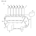
- FIG. 2A is a schematic view illustrating the refrigerant supply device and the circulation process of refrigerant in the battery pack according to the current embodiment.
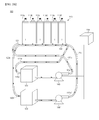
- FIG. 2B is another schematic view illustrating the refrigerant supply device and the circulation process of refrigerant in the battery pack according to the current embodiment.
- the battery pack 100 may further include a refrigerant supply device.
- the refrigerant supply device includes a branch supply pipe 120a, a first refrigerant supply pipe 120b, a second refrigerant supply pipe 120c, a first refrigerator discharge pipe 120d, a second refrigerator discharge pipe 120e, a branch discharge pipe 120f, a heat dissipation storage unit 130, a pump 140, and a control unit 150.
- the branch supply pipe 120a is connected to the pump 140 to be described later to function as a passage to which refrigerant is introduced.
- the first refrigerant supply pipe 120b may have a pipe shape with a hollow at the inside. A first end of the first refrigerant supply pipe 120b is connected to the branch supply pipe 120a. A second end of the first refrigerant supply pipe 120b is connected to the first side of the first refrigerant circulation pipe 121.
- the first refrigerant supply pipe 120b functions as a passage configured to introduce refrigerant introduced from the branch supply pipe 120a to the first refrigerant circulation pipe 121.
- the second refrigerant supply pipe 120c may have a pipe shape with a hollow at the inside. A first end of the second refrigerant supply pipe 120c is connected to the branch supply pipe 120a. A second end of the second refrigerant supply pipe 120c is connected to the second side of the second refrigerant circulation pipe 122.
- the second refrigerant supply pipe 120c functions as a passage configured to introduce refrigerant introduced from the branch supply pipe 120a to the second refrigerant circulation pipe 122.
- the first refrigerant discharge pipe 120d may have a pipe shape with a hollow at the inside. A first end of the first refrigerant discharge pipe 120d is connected to the second side of the first refrigerant circulation pipe 121.
- the first refrigerant discharge pipe 120d functions as a passage through which refrigerant of the first refrigerant circulation pipe 121 is discharged after cooling the battery cells 110.
- the second refrigerant discharge pipe 120e may have a pipe shape with a hollow at the inside. A first end of the second refrigerant discharge pipe 120e is connected to the first side of the second refrigerant circulation pipe 122.
- the second refrigerant discharge pipe 120e functions as a passage through which refrigerant of the second refrigerant circulation pipe 122 is discharged after cooling refrigerant of the first refrigerant circulation pipe 121.
- the branch discharge pipe 120f may have a pipe shape with a hollow at the inside.
- the branch discharge pipe 120f is connected to a second end of the first refrigerant discharge pipe 120d and a second end of the second refrigerant discharge pipe 120e.
- the branch discharge pipe 120f functions as a passage to discharge refrigerator of the first refrigerant discharge pipe 120d and refrigerator of the second refrigerant discharge pipe 120e to the heat dissipation storage unit 130 to be described later.
- the heat dissipation storage unit 130 cools refrigerant introduced through the branch discharge pipe 120f.
- the heat dissipation storage unit 130 may include a heat dissipation plate.
- the heat dissipation storage unit 130 stores cooled refrigerant.
- the pump 140 introduces refrigerant cooled and stored at the heat dissipation storage unit 130 to the branch supply pipe 120a.
- the control unit 150 measures the temperature of the battery cells 110 to control the heat dissipation storage unit 130 and the pump 140. In detail, when a temperature value of the battery cell 110 is greater than a predetermined reference temperature value, the control unit 150 operates the heat dissipation storage unit 130 and the pump 140. When a temperature value of the battery cell 110 is less than the predetermined reference temperature value, the control unit 150 may stop the heat dissipation storage unit 130 and the pump 140.
- the predetermined reference temperature value is temperature staring to degrade the performance of the battery pack 100 and may be about 60 °C. Instead of continually circulating refrigerant, the battery cells 110 are cooled only at a necessary time by the operation of the control unit 150. Thus, the control unit 150 can suppress the loss of the entire power of the battery pack 100.
- the refrigerant supply device illustrated in FIG. 2A includes the single heat dissipation storage unit 130 and the single pump 140
- the refrigerant supply device may include a plurality of heat dissipation storage units and a plurality of single pumps.
- a refrigerant supply device may include two heat dissipation storage units 130 and 130' and two pumps 140 and 140' connected between the control unit 150 and the heat dissipation storage units 130 and 130'.
- the second refrigerant supply pipe 120c for supplying refrigerant to the second refrigerant circulation pipe 122 is connected to a branch supply pipe 120a' connected to the pump 140'.
- the second refrigerant discharge pipe 120e for discharging refrigerant from the second refrigerant circulation pipe 122 is connected to a branch discharge pipe 120f' connected to the heat dissipation storage unit 130'.
- the refrigerant supply device illustrated in FIG. 2B uses the two pumps 140 and 140' to independently control circulation of refrigerant through the first refrigerant circulation pipe 121 and circulation of refrigerant through the second refrigerant circulation pipe 122, so as to prevent a pump overload occurring in the case where a single pump is used to control both circulation of refrigerant through the first refrigerant circulation pipe 121 and circulation of refrigerant through the second refrigerant circulation pipe 122.
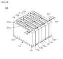
- FIG. 3 is a perspective view illustrating the lower portion of the battery pack according to the current embodiment.
- a battery pack 200 according to the current embodiment is different from the battery pack 100 of FIG. 1 in structures of a first refrigerant circulation pipe 221 and a second refrigerant circulation pipe 222.
- the battery pack 200 will now be described with respect to the first refrigerant circulation pipe 221 and the second refrigerant circulation pipe 222.
- Like reference numerals denote like elements in the battery pack 100 of FIG. 1 and the battery pack 200, and descriptions thereof will be omitted.
- the first refrigerant circulation pipe 221 extends from the first side of the battery cells 110 to the second side, may have a pipe shape with a hollow at the inside.
- the first refrigerant circulation pipe 221 has a first surface that is adjacent to the outer surfaces of the battery cells 110. In detail, the upper surface of the first refrigerant circulation pipe 221 may directly contact the lower surfaces of the battery cells 110.
- the first refrigerant circulation pipe 221 is configured to supply refrigerant from the first side of the battery cells 110 through the hollow at the inside.
- the first refrigerant circulation pipe 221 may be configured to supply refrigerant from the side where the first battery cell 110a is disposed.
- the first refrigerant circulation pipe 221 may include a first parallel pipe 221 a, a vertical pipe 221b, and a second parallel pipe 221c.
- a first surface of the first parallel pipe 221a is adjacent to or in direct contact with a battery cell, for example the first battery cell 110a.
- the first parallel pipe 221a extends along the width direction of the first battery cell 110a.
- the vertical pipe 221b is bent and extended from the first parallel pipe 221 a to the second side of the battery cells 110.
- the second parallel pipe 221c is bent and extended from the vertical pipe 221b.
- a first surface of the second parallel pipe 221c is adjacent to or in direct contact with the second battery cell 110b adjacent to the first battery cell 110a.
- the second parallel pipe 221c extends along the width direction of the second battery cell 110b.
- the first parallel pipe 221a, the vertical pipe 221b, and the second parallel pipe 221c of the first refrigerant circulation pipe 221 may be repeatedly formed according to the number and the size of the battery cells 110.
- the second refrigerant circulation pipe 222 may be the same in shape as the first refrigerant circulation pipe 221.
- the second refrigerant circulation pipe 222 is adjacent to a second surface of the first refrigerant circulation pipe 221.
- the second refrigerant circulation pipe 222 may directly contact the lower surface of the first refrigerant circulation pipe 221.
- the second refrigerant circulation pipe 222 is configured to supply refrigerant from the second side of the battery cells 110 through the hollow at the inside.
- the second refrigerant circulation pipe 222 may overlap and be parallel to the second surface of the first refrigerant circulation pipe 221 to correspond to the position of the first refrigerant circulation pipe 221.
- the second refrigerant circulation pipe 222 may include a first parallel pipe 222a, a vertical pipe 222b, and a second parallel pipe 222c.
- a first surface of the first parallel pipe 222a is adjacent to or in direct contact with the second surface of the first parallel pipe 221 a of the first refrigerant circulation pipe 221.
- the first parallel pipe 222a extends along the width direction of the first battery cell 110a.
- the vertical pipe 222b is bent and extended from the first parallel pipe 222a to the second side of the battery cells 110.
- the vertical pipe 222b is adj acent to or in direct contact with the vertical pipe 221b of the first refrigerant circulation pipe 221.
- the second parallel pipe 222c is bent and extended from the vertical pipe 222b.
- the second parallel pipe 222c is adjacent to or in direct contact with the second parallel pipe 221c of the first refrigerant circulation pipe 221.
- the second parallel pipe 222c extends along the width direction of the second battery cell 110b.
- the first parallel pipe 222a, the vertical pipe 222b, and the second parallel pipe 222c of the second refrigerant circulation pipe 222 may be repeatedly formed according to the number and the size of the battery cells 110.
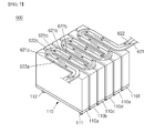
- FIG. 4 is a perspective view illustrating the lower portion of the battery pack according to the current embodiment.
- a battery pack 300 according to the current embodiment is different from the battery pack 100 of FIG. 1 in structures of a first refrigerant circulation pipe 321 and a second refrigerant circulation pipe 322.
- the battery pack 300 will now be described with respect to the first refrigerant circulation pipe 321 and the second refrigerant circulation pipe 322.
- Like reference numerals denote like elements in the battery pack 100 of FIG. 1 and the battery pack 300, and descriptions thereof will be omitted.
- the first refrigerant circulation pipe 321 extends from the first side of the battery cells 110 to the second side, may have a pipe shape with a hollow at the inside.
- the first refrigerant circulation pipe 321 has a first surface adjacent to the battery cells 110.
- the upper surface of the first refrigerant circulation pipe 321 may directly contact the lower surfaces of the battery cells 110.
- the first refrigerant circulation pipe 321 is configured to supply refrigerant from the first side of the battery cells 110 through the hollow at the inside.
- the first refrigerant circulation pipe 321 may be configured to supply refrigerant from the side where the first battery cell 110a is disposed.
- the first refrigerant circulation pipe 321 may include a first extension pipe 321a, a second extension pipe 321b, and a curve pipe 321c.
- the first extension pipe 321a has a first surface that is adjacent to or in direct contact with a battery cell, for example the first battery cell 110a.
- the first extension pipe 321a extends along the width direction of the first battery cell 110a.
- the second extension pipe 321b has a first surface that is adjacent to or in direct contact with the second battery cell 110b adjacent to the first battery cell 110a.
- the second extension pipe 321b extends along the width direction of the second battery cell 110b.
- the curve pipe 321c connects the first extension pipe 321a to the second extension pipe 321b in a curve shape. Due to the curve shape of the curve pipe 321c, refrigerant flows efficiently.
- the first extension pipe 321a, the second extension pipe 321b, and the curve pipe 321c of the first refrigerant circulation pipe 321 may be repeatedly formed according to the number and the size of the battery cells 110.
- the second refrigerant circulation pipe 322 may be the same in shape as the first refrigerant circulation pipe 321.
- the second refrigerant circulation pipe 322 is adjacent to a second surface of the first refrigerant circulation pipe 321.
- the second refrigerant circulation pipe 322 may be adjacent to or in direct contact with the lower surface of the first refrigerant circulation pipe 321.
- the second refrigerant circulation pipe 322 is configured to supply refrigerant to the second side of the battery cells 110 through the hollow at the inside.
- the second refrigerant circulation pipe 322 may overlap and be parallel to the second surface of the first refrigerant circulation pipe 321 to correspond to the position of the first refrigerant circulation pipe 321.
- the second refrigerant circulation pipe 322 may include a first extension pipe 322a, a second extension pipe 322b, and a curve pipe 322c.
- the first extension pipe 322a has a first surface that is adjacent to or in direct contact with a second surface of the first extension pipe 321a of the first refrigerant circulation pipe 321.
- the first extension pipe 322a extends along the width direction of the first battery cell 110a.
- the second extension pipe 322b has a first surface that is in direct contact with a second surface of the second extension pipe 321b of the first refrigerant circulation pipe 321.
- the second extension pipe 322b extends along the width direction of the second battery cell 110b.
- the curve pipe 322c connects the first extension pipe 322a to the second extension pipe 322b in a curve shape. Due to the curve shape of the curve pipe 322c, refrigerant flows efficiently.
- the first extension pipe 322a, the second extension pipe 322b, and the curve pipe 322c of the second refrigerant circulation pipe 322 may be repeatedly formed according to the number and the size of the battery cells 110.
- FIG. 5 is a perspective view illustrating the battery pack according to the current embodiment.
- a battery pack 400 according to the current embodiment is different from the battery pack 100 of FIG. 1 in structures of a first refrigerant circulation pipe 421 and a second refrigerant circulation pipe 422.
- the battery pack 400 will now be described with respect to the first refrigerant circulation pipe 421 and the second refrigerant circulation pipe 422.
- Like reference numerals denote like elements in the battery pack 100 of FIG. 1 and the battery pack 400, and descriptions thereof will be omitted.
- the first refrigerant circulation pipe 421 extends from the first side of the battery cells 110 to the second side, may have a pipe shape with a hollow at the inside.
- the first refrigerant circulation pipe 421 is adjacent to the outer surfaces of the battery cells 110.
- the upper surface of the first refrigerant circulation pipe 421 may directly contact the lower surfaces of the battery cells 110.
- the first refrigerant circulation pipe 421 may be formed of one of copper and aluminum, which have high heat conductivity.
- the first refrigerant circulation pipe 421 is configured to supply refrigerant from the first side of the battery cells 110 through the hollow at the inside.
- the first refrigerant circulation pipe 421 may be configured to supply refrigerant from the side where the first battery cell 110a is disposed.
- the second refrigerant circulation pipe 422 extends from the first side of the battery cells 110 to the second side, may have a pipe shape with a hollow at the inside.
- the second refrigerant circulation pipe 422 is adjacent to the outer surfaces of the battery cells 110 and to the first refrigerant circulation pipe 421.
- the second refrigerant circulation pipe 422 may directly contact the lower surfaces of the battery cells 110 and a side surface of the first refrigerant circulation pipe 421.
- the second refrigerant circulation pipe 422 may be formed of one of copper and aluminum, which have high heat conductivity.
- the second refrigerant circulation pipe 422 is configured to supply refrigerant from the second side of the battery cells 110 through the hollow at the inside.
- the second refrigerant circulation pipe 422 may be configured to supply refrigerant from the side where the sixth battery cell 110f is disposed.
- the sum of a width W1 of the first refrigerant circulation pipe 421 and a width W2 of the second refrigerant circulation pipe 422 may be equal to the width W of the battery cell 110. Accordingly, heat generated when the battery cells 110 are charged and discharged is effectively cooled by the first refrigerant circulation pipe 421 and the second refrigerant circulation pipe 422. Since the sum of the width W1 of the first refrigerant circulation pipe 421 and the width W2 of the second refrigerant circulation pipe 422 is equal to the width W of the battery cell 110, the arrangement and structure of the battery cells 110, the first refrigerant circulation pipe 421, and the second refrigerant circulation pipe 422 can be stable.
- the battery cells 110 can be effectively cooled in a balance state.
- FIG. 6 is a perspective view illustrating the lower portion of the battery pack according to the current embodiment.
- a battery pack 500 according to the current embodiment is different from the battery pack 100 of FIG. 1 in structures of a first refrigerant circulation pipe 521 and a second refrigerant circulation pipe 522.
- the battery pack 500 will now be described with respect to the first refrigerant circulation pipe 521 and the second refrigerant circulation pipe 522.
- Like reference numerals denote like elements in the battery pack 100 of FIG. 1 and the battery pack 500, and descriptions thereof will be omitted.
- the first refrigerant circulation pipe 521 extends from the first side of the battery cells 110 to the second side, may have a pipe shape with a hollow at the inside.
- the first refrigerant circulation pipe 521 has a first surface adjacent to the battery cells 110.
- the upper surface of the first refrigerant circulation pipe 521 may directly contact the lower surfaces of the battery cells 110.
- the first refrigerant circulation pipe 521 is configured to supply refrigerant from the first side of the battery cells 110 through the hollow at the inside.
- the first refrigerant circulation pipe 521 may be configured to supply refrigerant from the side where the first battery cell 110a is disposed.
- the first refrigerant circulation pipe 521 may include a first parallel pipe 521a, a first vertical pipe 521b, and a second parallel pipe 521c.
- a first surface of the first parallel pipe 52 1 a is adj acent to or in direct contact with a battery cell, for example the first battery cell 110a.
- the first parallel pipe 521 a extends along the width direction of the first battery cell 110a.
- the first vertical pipe 521b is bent and extended from the first parallel pipe 521 a to the second side of the battery cells 110.
- the second parallel pipe 521c is bent and extended from the first vertical pipe 521b.
- a first surface of the second parallel pipe 521c is adjacent to or in direct contact with the second battery cell 110b adjacent to the first battery cell 110a.
- the second parallel pipe 521c extends along the width direction of the second battery cell 110b.
- the first parallel pipe 521a, the first vertical pipe 521b, and the second parallel pipe 521c of the first refrigerant circulation pipe 521 may be repeatedly formed according to the number and the size of the battery cells 110.
- the second refrigerant circulation pipe 522 extends from the first side of the battery cells 110 to the second side, may have a pipe shape with a hollow at the inside.
- the second refrigerant circulation pipe 522 is adjacent to the battery cells 110 and the first refrigerant circulation pipe 521.
- the second refrigerant circulation pipe 522 is configured to supply refrigerant from the second side of the battery cells 110 through the hollow at the inside.
- the second refrigerant circulation pipe 522 may be configured to supply refrigerant from the side where the sixth battery cell 110f is disposed.
- the second refrigerant circulation pipe 522 may include a third parallel pipe 522a, a second vertical pipe 522b, and a fourth parallel pipe 522c.
- a first surface of the third parallel pipe 522a is adjacent to or in direct contact with the first battery cell 110a and the first parallel pipe 521a.
- the third parallel pipe 522a extends along the width direction of the first battery cell 110a.
- the second vertical pipe 522b is bent and extended from the third parallel pipe 522a to the second side of the battery cells 110.
- the second vertical pipe 522b is adjacent to or in direct contact with the first vertical pipe 521b.
- the fourth parallel pipe 522c is bent and extended from the second vertical pipe 522b.
- the fourth parallel pipe 522c is adjacent to or in direct contact with the second parallel pipe 521c and the second battery cell 110b.
- the fourth parallel pipe 522c extends along the width direction of the second battery cell 110b.
- the third parallel pipe 522a, the second vertical pipe 522b, and the fourth parallel pipe 522c of the second refrigerant circulation pipe 522 may be repeatedly formed according to the number and the size of the battery cells 110.
- FIG. 7 is a perspective view illustrating the lower portion of the battery pack according to the current embodiment.
- a battery pack 600 according to the current embodiment is different from the battery pack 100 of FIG. 1 in structures of a first refrigerant circulation pipe 621 and a second refrigerant circulation pipe 622.
- the battery pack 600 will now be described with respect to the first refrigerant circulation pipe 621 and the second refrigerant circulation pipe 622.
- Like reference numerals denote like elements in the battery pack 100 of FIG. 1 and the battery pack 600, and descriptions thereof will be omitted.
- the first refrigerant circulation pipe 621 extends from the first side of the battery cells 110 to the second side, may have a pipe shape with a hollow at the inside.
- the first refrigerant circulation pipe 621 has a first surface adjacent to the battery cells 110.
- the upper surface of the first refrigerant circulation pipe 621 may directly contact the lower surfaces of the battery cells 110.
- the first refrigerant circulation pipe 621 is configured to supply refrigerant from the first side of the battery cells 110 through the hollow at the inside.
- the first refrigerant circulation pipe 621 may be configured to supply refrigerant from the side where the first battery cell 110a is disposed.
- the first refrigerant circulation pipe 621 may include a first extension pipe 621a, a second extension pipe 621b, and a first curve pipe 621c.
- a first surface of the first extension pipe 621a is adjacent to or in direct contact with a battery cell, for example the first battery cell 110a.
- the first extension pipe 621a extends along the width direction of the first battery cell 110a.
- a first surface of the second extension pipe 621b is adjacent to or in direct contact with the second battery cell 110b adjacent to the first battery cell 110a.
- the second extension pipe 621b extends along the width direction of the second battery cell 110b.
- the first curve pipe 621c connects the first extension pipe 621a to the second extension pipe 621b in a curve shape. Due to the curve shape of the first curve pipe 621 c, refrigerant flows efficiently.
- the first extension pipe 621a, the second extension pipe 621b, and the first curve pipe 621c of the first refrigerant circulation pipe 621 may be repeatedly formed according to the number and the size of the battery cells 110.
- the second refrigerant circulation pipe 622 extends from the first side of the battery cells 110 to the second side, may have a pipe shape with a hollow at the inside.
- the second refrigerant circulation pipe 622 is adjacent to the first refrigerant circulation pipe 621 and the battery cells 110.
- the second refrigerant circulation pipe 622 may directly contact a side surface of the first refrigerant circulation pipe 621 and the lower surfaces of the battery cells 110.
- the second refrigerant circulation pipe 622 is configured to supply refrigerant from the second side of the battery cells 110 through the hollow at the inside.
- the second refrigerant circulation pipe 622 may be configured to supply refrigerant from the side where the sixth battery cell 110f is disposed.
- the second refrigerant circulation pipe 622 may include a third extension pipe 622a, a fourth extension pipe 622b, and a second curve pipe 622c.
- the third extension pipe 622a is adjacent to or in direct contact with the first extension pipe 621a of the first refrigerant circulation pipe 621, and the first battery cell 110a.
- the third extension pipe 622a extends along the width direction of the first battery cell 110a.
- the fourth extension pipe 622b is adjacent to or in direct contact with the second extension pipe 621b of the first refrigerant circulation pipe 621, and the second battery cell 110b.
- the fourth extension pipe 622b extends along the width direction of the second battery cell 110b.
- the second curve pipe 622c is adjacent to or in direct contact with the first curve pipe 621c of the first refrigerant circulation pipe 621.
- the second curve pipe 622c connects the third extension pipe 622a to the fourth extension pipe 622b in a curve shape. Due to the curve shape of the second curve pipe 622c, refrigerant flows efficiently.
- the third extension pipe 622a, the fourth extension pipe 622b, and the second curve pipe 622c of the second refrigerant circulation pipe 622 may be repeatedly formed according to the number and the size of the battery cells 110.
- FIG. 8 is a perspective view illustrating the battery pack according to the current embodiment.
- a battery pack 700 according to the current embodiment is different from the battery pack 100 of FIG. 1 in that the battery pack 700 includes an intermediate medium 710.
- the battery pack 700 will now be described with respect to the intermediate medium 710.
- Like reference numerals denote like elements in the battery pack 100 of FIG. 1 and the battery pack 700, and descriptions thereof will be omitted.
- the intermediate medium 710 is disposed between the battery cells 110 and the first refrigerant circulation pipe 121. When heat is generated during charge/discharge of the battery cells 110, the intermediate medium 710 uniformly transfers the heat to the first refrigerant circulation pipe 121, without concentrating the heat on a place. Accordingly, the intermediate medium 710 effectively removes heat generated during charge/discharge of the battery cells 110.
- the intermediate medium 710 may be formed of a material with a thermal conductivity of greater than 100 W/(m*K).
- the intermediate medium 710 may have a thin plate shape, and be formed of a metal material having high heat conductivity, such as copper and aluminum.
- the intermediate medium 710 is disposed between the battery cells 110 and the first refrigerant circulation pipe 121 in FIG. 8 , when the battery cells 110 contact the first and second refrigerant circulation pipes 421 and 422 at the same time as illustrated in FIG. 5 , the intermediate medium 710 may be disposed between the battery cells 110 and the first refrigerant circulation pipe 421, and simultaneously, be disposed between the battery cells 110 and the second refrigerant circulation pipe 422.
- FIG. 9 is a perspective view illustrating the battery pack according to the current embodiment.
- a battery pack 800 according to the current embodiment is different from the battery pack 100 of FIG. 1 in that the battery pack 800 includes an intermediate medium 810.
- the battery pack 800 will now be described with respect to the intermediate medium 810.
- Like reference numerals denote like elements in the battery pack 100 of FIG. 1 and the battery pack 800, and descriptions thereof will be omitted.
- the intermediate medium 810 is disposed between the first refrigerant circulation pipe 121 and the second refrigerant circulation pipe 122.
- the intermediate medium 810 uniformly transfers the heat to the second refrigerant circulation pipe 122, without concentrating the heat on a place. Accordingly, the intermediate medium 810 effectively removes heat generated during charge/discharge of the battery cells 110.
- the intermediate medium 810 may be formed of a material with a thermal conductivity of greater than 100 W/(m*K).
- the intermediate medium 810 may have a thin plate shape, and be formed of a metal material having high heat conductivity, such as copper and aluminum.
Landscapes
- Engineering & Computer Science (AREA)
- Chemical & Material Sciences (AREA)
- Manufacturing & Machinery (AREA)
- Chemical Kinetics & Catalysis (AREA)
- Electrochemistry (AREA)
- General Chemical & Material Sciences (AREA)
- Physics & Mathematics (AREA)
- Combustion & Propulsion (AREA)
- Mechanical Engineering (AREA)
- Thermal Sciences (AREA)
- General Engineering & Computer Science (AREA)
- General Physics & Mathematics (AREA)
- Automation & Control Theory (AREA)
- Secondary Cells (AREA)
- Battery Mounting, Suspending (AREA)
Abstract
Description
- Embodiments relate to a battery pack.
- Unlike a primary battery that is not rechargeable, a secondary battery is a rechargeable and dischargeable battery. Such a secondary battery is used as a battery pack formed by electrically connecting a plurality of battery cells to each other, so that the secondary battery can be used in a device such as electric vehicles and uninterruptable power supplies, which have larger capacity requirements than portable electronic devices.
- When being repeatedly charged and discharged, each battery cell of a battery pack is heated. If heat generated by the repeated charging and discharging is not cooled in the battery pack, each battery cell is degraded. Furthermore, heat generated from each battery cell degrades the whole performance of the battery pack. In addition, when a plurality of heated battery cells is unevenly cooled, the whole performance of a battery pack is degraded.
- An aspect of the present invention provides a battery pack that can uniformly cool a plurality of battery cells so as to significantly improve stability.
- According to an aspect of the present invention, a battery pack is disclosed, comprising: a plurality of battery cells electrically connected to one another and arranged to extend from a first side to a second side of the battery pack; a first refrigerant circulation pipe arranged adjacent to the plurality of battery cells; a second refrigerant circulation pipe arranged adjacent to the first refrigerant circulation pipe; wherein the first refrigerant circulation pipe is adapted to guide a refrigerant from the first side to the second side of the battery pack and the second refrigerant circulation pipe is adapted to guide a refrigerant from the second side of the battery pack to the first side of the battery pack.
- Preferably at least one of the first refrigerant circulation pipe and the second refrigerant circulation pipe directly contacts the plurality of battery cells. Preferably the first refrigerant circulation pipe directly contacts the second refrigerant circulation pipe.
- Preferably an intermediate medium adapted to uniformly transfer heat is interposed between the plurality of battery cells and the first refrigerant circulation pipe. Preferably an intermediate medium adapted to uniformly transfer heat is interposed between the first refrigerant circulation pipe and the second refrigerant circulation pipe.
- Preferably the battery pack further comprises: a first refrigerant supply pipe connected to a first end of the first refrigerant circulation pipe, the first end of the first refrigerant circulation pipe being located adjacent to the first side of the battery pack; a first refrigerant discharge pipe connected to a second end of the first refrigerant circulation pipe, the second end of the first refrigerant circulation pipe being located adjacent to the second side of the battery pack; a second refrigerant supply pipe connected to a first end of the second refrigerant circulation pipe, the first end of the second refrigerant circulation pipe being located adjacent to the second side of the battery pack; a second refrigerant discharge pipe connected to a second end of the second refrigerant circulation pipe, the second end of the second refrigerant circulation pipe being located adjacent to the first side of the battery pack; at least one pump adapted to supply a refrigerant to the first refrigerant supply pipe and to the second refrigerant supply pipe; and a heat dissipation storage unit connected to the first refrigerant supply pipe, the second refrigerant supply pipe, the first refrigerant discharge pipe and the second refrigerant discharge pipe and being adapted to cool a refrigerant from the first refrigerant discharge pipe and the second refrigerant discharge pipe.
- Preferably the battery pack further comprises a control unit adapted to determine a temperature of each of the plurality of battery cells and to control the at least one pump depending on the determined temperatures of the plurality of battery cells. Preferably the control unit is adapted to activate the at least one pump when a highest temperature of the plurality of battery cells is greater than a first predetermined value. Preferably the control unit is adapted to deactivate the at least one pump when a highest temperature of the plurality of battery cells is smaller than a second predetermined value. Preferably the
first predetermined value is greater than the second predetermined value. Preferably each of the first refrigerant circulation pipe and/or the second refrigerant circulation pipe is formed of a material with a thermal conductivity of greater than 100 W/(m*K). - Preferably the first refrigerant circulation pipe is formed along a first circulation path between the first side and the second side of the battery pack and the second refrigerant circulation pipe is formed along a second circulation path between the first side and the second side of the battery pack, wherein the first circulation path is arranged concurrent with the second circulation path.
- Preferably the first refrigerant circulation pipe and the second refrigerant circulation pipe are arranged side by side.
- Preferably the second refrigerant circulation pipe is stacked on the first refrigerant circulation pipe.
- Preferably the shape of the first refrigerant circulation pipe is the same as the shape of the second refrigerant circulation pipe.
- Preferably a width of the first refrigerant circulation pipe and a width of the second refrigerant circulation pipe is the same as a width of the plurality of battery cells. Preferably the sum of a width of the first refrigerant circulation pipe and a width of the second refrigerant circulation pipe is the same as a width of the plurality of battery cells.
- Preferably each of the first refrigerant circulation pipe and the second refrigerant circulation pipe comprises a longish, strip-like shape having a uniform width along its extension from the first side to the second side of the battery pack.
- Preferably each of the first refrigerant circulation pipe and the second refrigerant circulation pipe comprises parallel portions corresponding to the number and location of the plurality of battery cells, each parallel portion contacting one of the plurality of battery cells and extending in a direction perpendicular to an axis extending from the first side to the second side of the battery pack, wherein the parallel portions of the first refrigerant circulation pipe interdigitate with the parallel portions of the second refrigerant circulation pipe, and wherein adjacent parallel portions are connected by connecting portions. Preferably the connecting portions are formed as vertical portions having a stripe-like shape, the longitudinal axes of the connecting portions being perpendicular to the parallel portions. Preferably the connecting portions are formed as curved portions. In other words, a zigzag configuration for the refrigerant circulation pipes is preferably used. The use of a zigzag configuration is advantageous in that the detrimental effects of a locally non uniform heat dissipation environment (adjacent to the refrigerant circulation pipes) can be efficiently compensation or suppressed compared to longish, strip-like circulation pipes.
- Preferably the first refrigerant circulation pipe is formed of a material with a high thermal conductivity. Preferably, the second refrigerant circulation pipe is formed of a material with a high thermal conductivity. Preferably, the intermediate medium is formed of a material with a high thermal conductivity. In the sense of the present invention, a material with a high thermal conductivity preferably comprises a thermal conductivity of greater than 100 W/(m*K), more preferably greater than 200 W/(m*K), more preferably greater than 300 W/(m*K) and still more preferably greater than 400 W/(m*K).
- Preferably the refrigerant is a liquid refrigerant (at a temperature of 20°C). Preferably the refrigerant comprises a material having a heat capacity which is at least 20% of the heat capacity of carbon dioxide, more preferably at least 50% of the heat capacity of carbon dioxide, more preferably at least 70% of the heat capacity of carbon dioxide, and still more preferably at least 90% of the heat capacity of carbon dioxide(at a temperature of 20°C).
- Preferably the surface area of the refrigerant circulation pipes (i.e. first refrigerant circulation pipe and/or second refrigerant circulation pipe) which cover the lower side of the battery cells is at least 50% of the surface area of the lower side of the battery cells, more preferably more than 70%, still preferably more than 90% and still more preferably equal to 100%.
- Preferably, a refrigerant supply device may include two heat dissipation storage units and/or two pumps connected between the control unit and the heat dissipation storage units. Preferably the refrigerant supply device uses the two pumps to independently control circulation of refrigerant through the first refrigerant circulation pipe and circulation of refrigerant through the second refrigerant circulation pipe, so as to prevent a pump overload occurring in the case where a single pump is used to control both circulation of refrigerant through the first refrigerant circulation pipe and circulation of refrigerant through the second refrigerant circulation pipe. Preferably the two pumps may circulate the refrigerants in the first and second refrigerant circulation pipes with different speeds. Such a modified cooling process may result in a better balancing, for example if the first end of the battery stack would is exposed to heat from adjacent (other) devices (located in the close periphery of the first end of the battery stack), then the speed of the first refrigerant circulation pipe might be controlled to be greater than that of the second refrigerant circulation pipe. Preferably the control unit is adapted to determine the temperature profile of the battery stack along a direction extending from the first side to the second side (by determining the respective temperature of each of the battery cells) and to circulate the refrigerants in the first and second refrigerant circulation pipes with different speeds so as to balance the temperature profile of the battery stack.
- According to at least one of embodiments, a battery pack includes: a plurality of battery cells arrayed from a first side to a second side; a first refrigerant circulation pipe having a first surface adjacent to outer surfaces of the battery cells, the first refrigerant circulation pipe extending from the first side of the battery cells to the second side, the first refrigerant circulation pipe being configured to supply refrigerant from the first side; and a second refrigerant circulation pipe adjacent to a second surface of the first refrigerant circulation pipe and extending from the first side of the battery cells to the second side, the second refrigerant circulation pipe being configured to supply refrigerant from the second side.
- The battery pack may further include a first refrigerant supply pipe connected to a first side of the first refrigerant circulation pipe; a second refrigerant supply pipe connected to a second side of the second refrigerant circulation pipe; a pump configured to supply refrigerant to the first and second refrigerant supply pipes; a first refrigerant discharge pipe connected to a second side of the first refrigerant circulation pipe; a second refrigerant discharge pipe connected to a first side of the second refrigerant circulation pipe; and a heat dissipation storage unit configured to cool and store refrigerant discharged from the first and second refrigerant supply pipes and supply the cooled refrigerant to the pump.
- The battery pack may further include a control unit configured to measure temperature of the battery cells and control operations of the pump and the heat dissipation storage unit according to a predetermined reference temperature value.
- The first and second refrigerant supply pipes may receive refrigerant through branch supply pipes connected to the pump.
- The first and second refrigerant circulation pipes each may have a pipe shape with a hollow at an inside from the first side of the battery cells to the second side.
- The battery cell, the first refrigerant circulation pipe, and the second refrigerant circulation pipe may be identical in width.
- The first refrigerant circulation pipe may include a first parallel pipe adjacent to one of the battery cells and extending along a width direction of the battery cell; a vertical pipe bent and extending from the first parallel pipe to the second side of the battery cells; and a second parallel pipe bent from the vertical pipe and extending along the width direction of the battery cell.
- The second refrigerant circulation pipe may be identical in shape as the first refrigerant circulation pipe, and be adjacent to the second surface of the first refrigerant circulation pipe to correspond to a position of the first refrigerant circulation pipe.
- The first refrigerant circulation pipe may include a first extension pipe adjacent to one of the battery cells and extending along the width direction of the battery cell; a second extension pipe adjacent to the battery cell adjacent to the battery cell to which the first extension pipe is adjacent, and extending along the width direction of the battery cell; and a curve pipe connecting the first extension pipe to the second extension pipe in a curve shape.
- The second refrigerant circulation pipe may be identical in shape as the first refrigerant circulation pipe, and be adjacent to the second surface of the first refrigerant circulation pipe to correspond to the position of the first refrigerant circulation pipe.
- The first surface of the first refrigerant circulation pipe may (preferably directly) contact the outer surfaces of the battery cells, and the second refrigerant circulation pipe may (preferably directly) contact the second surface of the first refrigerant circulation pipe.
- According to another embodiment, a battery pack includes: a plurality of battery cells arrayed from a first side to a second side; a first refrigerant circulation pipe adjacent to outer surfaces of the battery cells, the first refrigerant circulation pipe extending from the first side of the battery cells to the second side, the first refrigerant circulation pipe being configured to supply refrigerant from the first side; and a second refrigerant circulation pipe adjacent to the outer surfaces of the battery cells, and the first refrigerant circulation pipe, the second refrigerant circulation pipe extending from the first side of the battery cells to the second side, the second refrigerant circulation pipe being configured to supply refrigerant from the second side.
- The battery pack may further include a first refrigerant supply pipe connected to a first side of the first refrigerant circulation pipe; a second refrigerant supply pipe connected to a second side of the second refrigerant circulation pipe; a pump configured to supply refrigerant to the first and second refrigerant supply pipes; a first refrigerant discharge pipe connected to a second side of the first refrigerant circulation pipe; a second refrigerant discharge pipe connected to a first side of the second refrigerant circulation pipe; a heat dissipation storage unit configured to cool and store refrigerant discharged from the first and second refrigerant supply pipes and supply the cooled refrigerant to the pump; and a control unit configured to measure temperature of the battery cells and control operations of the pump and the heat dissipation storage unit according to a predetermined reference temperature value.
- The first and second refrigerant supply pipes may receive refrigerant through branch supply pipes connected to the pump.
- The first and second refrigerant circulation pipes each may have a pipe shape with a hollow at an inside from the first side of the battery cells to the second side.
- The sum of a width of the first refrigerant circulation pipe and a width of the second refrigerant circulation pipe may be equal to a width of the battery cell.
- The first refrigerant circulation pipe may include a first parallel pipe adjacent to one of the battery cells and extending along a width direction of the battery cell; a first vertical pipe bent and extending from the first parallel pipe to the second side of the battery cells; and a second parallel pipe bent from the first vertical pipe and extending along the width direction of the battery cell.
- The second refrigerant circulation pipe may include a third parallel pipe adjacent to one of the battery cells and the first parallel pipe and extending along the width direction of the battery cell; a second vertical pipe adjacent to the first vertical pipe and bent and extending from the third parallel pipe to the second side; and a fourth parallel pipe adjacent to the second parallel pipe and bent from the second vertical pipe and extending along the width direction of the battery cell.
- The first refrigerant circulation pipe may include a first extension pipe adjacent to one of the battery cells and extending along the width direction of the battery cell; a second extension pipe adjacent to the battery cell adjacent to the battery cell to which the first extension pipe is adjacent, and extending along the width direction of the battery cell; and a first curve pipe connecting the first extension pipe to the second extension pipe in a curve shape.
- The second refrigerant circulation pipe may include a third extension pipe adjacent to one of the battery cells and the first extension pipe and extending along the width direction of the battery cell; a fourth extension pipe adjacent to the battery cell adjacent to the battery cell to which the third extension pipe is adjacent, the fourth extension pipe being adjacent to the second extension pipe and extending along the width direction of the battery cell; and a second curve pipe adjacent to the first curve pipe and connecting the third extension pipe to the fourth extension pipe in a curve shape.
- The first refrigerant circulation pipe may (preferably directly) contact the outer surfaces of the battery cells, and the second refrigerant circulation pipe may (preferably directly) contact the outer surfaces of the battery cells and the first refrigerant circulation pipe.
- The first and second refrigerant circulation pipes may be formed of one of copper and aluminum.
- A battery pack according to embodiments includes refrigerant circulation pipes to cool heat generated when battery cells are repeatedly charged and discharged. The refrigerant circulation pipes in both directions uniformly cool the battery cells in the battery pack, so as to improve the stability and service life of the battery pack.
- A battery pack according to embodiments includes a control unit configured to circulate refrigerant only at a necessary time and minimize the loss of power.
-
-
FIG. 1 is a perspective view illustrating a battery pack according to an embodiment. -
FIG. 2A is a schematic view illustrating a refrigerant supply device and the circulation process of refrigerant in a battery pack according to an embodiment. -
FIG. 2B is a schematic view illustrating a refrigerant supply device and the circulation process of refrigerant in a battery pack according to an embodiment. -
FIG. 3 is a perspective view illustrating the lower portion of a battery pack according to an embodiment. -
FIG. 4 is a perspective view illustrating the lower portion of a battery pack according to another embodiment. -
FIG. 5 is a perspective view illustrating a battery pack according to another embodiment. -
FIG. 6 is a perspective view illustrating the lower portion of a battery pack according to another embodiment. -
FIG. 7 is a perspective view illustrating the lower portion of a battery pack according to another embodiment. -
FIG. 8 is a perspective view illustrating a battery pack according to another embodiment. -
FIG. 9 is a perspective view illustrating a battery pack according to another embodiment. - Example embodiments will now be described more fully hereinafter with reference to the accompanying drawings; however, they may be embodied in different forms and should not be construed as limited to the embodiments set forth herein. Rather, these embodiments are provided so that this disclosure will be thorough and complete, and will fully convey the scope of the disclosure to those skilled in the art.
- Hereinafter, a configuration of a battery pack according to an embodiment will now be described.
-
FIG. 1 is a perspective view illustrating the battery pack according to the current embodiment. - Referring to
FIG. 1 , abattery pack 100 according to the current embodiment includesbattery cells 110, a firstrefrigerant circulation pipe 121, and a secondrefrigerant circulation pipe 122. - The
battery cell 110 includes afirst electrode terminal 111 and asecond electrode terminal 112. Thefirst electrode terminal 111 and thesecond electrode terminal 112 may be disposed at the upper portion of thebattery cell 110. However, the positions of thefirst electrode terminal 111 and thesecond electrode terminal 112 are not limited thereto. Thefirst electrode terminal 111 may have a positive or negative pole. Thesecond electrode terminal 112 has the opposite pole to that of thefirst electrode terminal 111. Thebattery cells 110 are arrayed from a first side to a second side. Thebattery cells 110 are classified into first throughsixth battery cells battery cells 110 is not limited thereto. Secondary batteries, which are chargeable and dischargeable, may be used as thebattery cells 110. Hereinafter, the large side of thebattery cell 110 is referred to as a width, and a direction along the width is referred to as a width direction. - The first
refrigerant circulation pipe 121 extends from the first side of thebattery cells 110 to the second side, may have a pipe shape with a hollow at the inside. The firstrefrigerant circulation pipe 121 has a first surface that is adjacent to the outer surfaces of thebattery cells 110. In detail, the upper surface of the firstrefrigerant circulation pipe 121 may directly contact the lower surfaces of thebattery cells 110. A width W of thebattery pack 100 may be equal to a width W of the firstrefrigerant circulation pipe 121. Accordingly, heat generated when thebattery cells 110 are charged and discharged can be effectively cooled. Since the width of thebattery cells 110 is equal to the width of the firstrefrigerant circulation pipe 121, the arrangement and structure of thebattery cells 110 can be stably formed in thebattery pack 100. In detail, the firstrefrigerant circulation pipe 121 may be formed of one of copper and aluminum, which have high heat conductivity. The firstrefrigerant circulation pipe 121 is configured to supply refrigerant from the first side of thebattery cells 110 through the hollow at the inside. In detail, the firstrefrigerant circulation pipe 121 may be configured to supply refrigerant from the side where thefirst battery cell 110a is disposed. - The second
refrigerant circulation pipe 122 extends from the first side of thebattery cells 110 to the second side, may have a pipe shape with a hollow at the inside. The secondrefrigerant circulation pipe 122 is adjacent to a second surface of the firstrefrigerant circulation pipe 121. In detail, the upper surface of the secondrefrigerant circulation pipe 122 may directly contact the lower surface of the firstrefrigerant circulation pipe 121. The width W of thebattery cells 110, the width W of the firstrefrigerant circulation pipe 121, and a width W of the secondrefrigerant circulation pipe 122 may be identical, and thus, thebattery cells 110, the firstrefrigerant circulation pipe 121, and the secondrefrigerant circulation pipe 122 can be structurally stable in thebattery pack 100. The secondrefrigerant circulation pipe 122 may be formed of one of copper and aluminum, which have high heat conductivity. The secondrefrigerant circulation pipe 122 is configured to supply refrigerant from the second side of thebattery cells 110 through the hollow at the inside. In detail, the secondrefrigerant circulation pipe 122 may be configured to supply refrigerant from the side where thesixth battery cell 110f is disposed. The secondrefrigerant circulation pipe 122 supplies refrigerant from the second side to effectively cool heated refrigerant at the second side of the firstrefrigerant circulation pipe 121 directly contacting the secondrefrigerant circulation pipe 122. - Refrigerant in the first
refrigerant circulation pipe 121 is heated while passing through the first throughsixth battery cells battery pack 100 according to the current embodiment, the secondrefrigerant circulation pipe 122 directly contacts the firstrefrigerant circulation pipe 121 to decrease the temperature of heated refrigerant at the second side of the firstrefrigerant circulation pipe 121. Thus, thebattery pack 100 can uniformly cool thebattery cells 110. - Hereinafter, a refrigerant supply device and a circulation process of refrigerant in a battery pack according to an embodiment will now be described.
-
FIG. 2A is a schematic view illustrating the refrigerant supply device and the circulation process of refrigerant in the battery pack according to the current embodiment.FIG. 2B is another schematic view illustrating the refrigerant supply device and the circulation process of refrigerant in the battery pack according to the current embodiment. - Referring to
FIG. 2A , thebattery pack 100 may further include a refrigerant supply device. The refrigerant supply device includes abranch supply pipe 120a, a firstrefrigerant supply pipe 120b, a secondrefrigerant supply pipe 120c, a firstrefrigerator discharge pipe 120d, a secondrefrigerator discharge pipe 120e, abranch discharge pipe 120f, a heatdissipation storage unit 130, apump 140, and acontrol unit 150. - The
branch supply pipe 120a is connected to thepump 140 to be described later to function as a passage to which refrigerant is introduced. - The first
refrigerant supply pipe 120b may have a pipe shape with a hollow at the inside. A first end of the firstrefrigerant supply pipe 120b is connected to thebranch supply pipe 120a. A second end of the firstrefrigerant supply pipe 120b is connected to the first side of the firstrefrigerant circulation pipe 121. The firstrefrigerant supply pipe 120b functions as a passage configured to introduce refrigerant introduced from thebranch supply pipe 120a to the firstrefrigerant circulation pipe 121. - The second
refrigerant supply pipe 120c may have a pipe shape with a hollow at the inside. A first end of the secondrefrigerant supply pipe 120c is connected to thebranch supply pipe 120a. A second end of the secondrefrigerant supply pipe 120c is connected to the second side of the secondrefrigerant circulation pipe 122. The secondrefrigerant supply pipe 120c functions as a passage configured to introduce refrigerant introduced from thebranch supply pipe 120a to the secondrefrigerant circulation pipe 122. - The first
refrigerant discharge pipe 120d may have a pipe shape with a hollow at the inside. A first end of the firstrefrigerant discharge pipe 120d is connected to the second side of the firstrefrigerant circulation pipe 121. The firstrefrigerant discharge pipe 120d functions as a passage through which refrigerant of the firstrefrigerant circulation pipe 121 is discharged after cooling thebattery cells 110. - The second
refrigerant discharge pipe 120e may have a pipe shape with a hollow at the inside. A first end of the secondrefrigerant discharge pipe 120e is connected to the first side of the secondrefrigerant circulation pipe 122. The secondrefrigerant discharge pipe 120e functions as a passage through which refrigerant of the secondrefrigerant circulation pipe 122 is discharged after cooling refrigerant of the firstrefrigerant circulation pipe 121. - The
branch discharge pipe 120f may have a pipe shape with a hollow at the inside. Thebranch discharge pipe 120f is connected to a second end of the firstrefrigerant discharge pipe 120d and a second end of the secondrefrigerant discharge pipe 120e. Thebranch discharge pipe 120f functions as a passage to discharge refrigerator of the firstrefrigerant discharge pipe 120d and refrigerator of the secondrefrigerant discharge pipe 120e to the heatdissipation storage unit 130 to be described later. - The heat
dissipation storage unit 130 cools refrigerant introduced through thebranch discharge pipe 120f. In detail, the heatdissipation storage unit 130 may include a heat dissipation plate. The heatdissipation storage unit 130 stores cooled refrigerant. - The
pump 140 introduces refrigerant cooled and stored at the heatdissipation storage unit 130 to thebranch supply pipe 120a. - The
control unit 150 measures the temperature of thebattery cells 110 to control the heatdissipation storage unit 130 and thepump 140. In detail, when a temperature value of thebattery cell 110 is greater than a predetermined reference temperature value, thecontrol unit 150 operates the heatdissipation storage unit 130 and thepump 140. When a temperature value of thebattery cell 110 is less than the predetermined reference temperature value, thecontrol unit 150 may stop the heatdissipation storage unit 130 and thepump 140. Here, the predetermined reference temperature value is temperature staring to degrade the performance of thebattery pack 100 and may be about 60 °C. Instead of continually circulating refrigerant, thebattery cells 110 are cooled only at a necessary time by the operation of thecontrol unit 150. Thus, thecontrol unit 150 can suppress the loss of the entire power of thebattery pack 100. - Although the refrigerant supply device illustrated in
FIG. 2A includes the single heatdissipation storage unit 130 and thesingle pump 140, the refrigerant supply device may include a plurality of heat dissipation storage units and a plurality of single pumps. For example, as illustrated inFIG. 2B , a refrigerant supply device may include two heatdissipation storage units 130 and 130' and twopumps 140 and 140' connected between thecontrol unit 150 and the heatdissipation storage units 130 and 130'. The secondrefrigerant supply pipe 120c for supplying refrigerant to the secondrefrigerant circulation pipe 122 is connected to abranch supply pipe 120a' connected to the pump 140'. The secondrefrigerant discharge pipe 120e for discharging refrigerant from the secondrefrigerant circulation pipe 122 is connected to abranch discharge pipe 120f' connected to the heat dissipation storage unit 130'. The refrigerant supply device illustrated inFIG. 2B uses the twopumps 140 and 140' to independently control circulation of refrigerant through the firstrefrigerant circulation pipe 121 and circulation of refrigerant through the secondrefrigerant circulation pipe 122, so as to prevent a pump overload occurring in the case where a single pump is used to control both circulation of refrigerant through the firstrefrigerant circulation pipe 121 and circulation of refrigerant through the secondrefrigerant circulation pipe 122. - Hereinafter, a configuration of a battery pack according to another embodiment will now be described.
-
FIG. 3 is a perspective view illustrating the lower portion of the battery pack according to the current embodiment. - Referring to
FIG. 3 , abattery pack 200 according to the current embodiment is different from thebattery pack 100 ofFIG. 1 in structures of a firstrefrigerant circulation pipe 221 and a secondrefrigerant circulation pipe 222. Thus, thebattery pack 200 will now be described with respect to the firstrefrigerant circulation pipe 221 and the secondrefrigerant circulation pipe 222. Like reference numerals denote like elements in thebattery pack 100 ofFIG. 1 and thebattery pack 200, and descriptions thereof will be omitted. - The first
refrigerant circulation pipe 221 extends from the first side of thebattery cells 110 to the second side, may have a pipe shape with a hollow at the inside. The firstrefrigerant circulation pipe 221 has a first surface that is adjacent to the outer surfaces of thebattery cells 110. In detail, the upper surface of the firstrefrigerant circulation pipe 221 may directly contact the lower surfaces of thebattery cells 110. The firstrefrigerant circulation pipe 221 is configured to supply refrigerant from the first side of thebattery cells 110 through the hollow at the inside. In detail, the firstrefrigerant circulation pipe 221 may be configured to supply refrigerant from the side where thefirst battery cell 110a is disposed. The firstrefrigerant circulation pipe 221 may include a firstparallel pipe 221 a, avertical pipe 221b, and a secondparallel pipe 221c. - A first surface of the first
parallel pipe 221a is adjacent to or in direct contact with a battery cell, for example thefirst battery cell 110a. The firstparallel pipe 221a extends along the width direction of thefirst battery cell 110a. - The
vertical pipe 221b is bent and extended from the firstparallel pipe 221 a to the second side of thebattery cells 110. - The second
parallel pipe 221c is bent and extended from thevertical pipe 221b. A first surface of the secondparallel pipe 221c is adjacent to or in direct contact with thesecond battery cell 110b adjacent to thefirst battery cell 110a. The secondparallel pipe 221c extends along the width direction of thesecond battery cell 110b. - The first
parallel pipe 221a, thevertical pipe 221b, and the secondparallel pipe 221c of the firstrefrigerant circulation pipe 221 may be repeatedly formed according to the number and the size of thebattery cells 110. - The second
refrigerant circulation pipe 222 may be the same in shape as the firstrefrigerant circulation pipe 221. The secondrefrigerant circulation pipe 222 is adjacent to a second surface of the firstrefrigerant circulation pipe 221. In detail, the secondrefrigerant circulation pipe 222 may directly contact the lower surface of the firstrefrigerant circulation pipe 221. The secondrefrigerant circulation pipe 222 is configured to supply refrigerant from the second side of thebattery cells 110 through the hollow at the inside. The secondrefrigerant circulation pipe 222 may overlap and be parallel to the second surface of the firstrefrigerant circulation pipe 221 to correspond to the position of the firstrefrigerant circulation pipe 221. The secondrefrigerant circulation pipe 222 may include a firstparallel pipe 222a, avertical pipe 222b, and a secondparallel pipe 222c. - A first surface of the first
parallel pipe 222a is adjacent to or in direct contact with the second surface of the firstparallel pipe 221 a of the firstrefrigerant circulation pipe 221. The firstparallel pipe 222a extends along the width direction of thefirst battery cell 110a. - The
vertical pipe 222b is bent and extended from the firstparallel pipe 222a to the second side of thebattery cells 110. Thevertical pipe 222b is adj acent to or in direct contact with thevertical pipe 221b of the firstrefrigerant circulation pipe 221. - The second
parallel pipe 222c is bent and extended from thevertical pipe 222b. The secondparallel pipe 222c is adjacent to or in direct contact with the secondparallel pipe 221c of the firstrefrigerant circulation pipe 221. The secondparallel pipe 222c extends along the width direction of thesecond battery cell 110b. - The first
parallel pipe 222a, thevertical pipe 222b, and the secondparallel pipe 222c of the secondrefrigerant circulation pipe 222 may be repeatedly formed according to the number and the size of thebattery cells 110. - Hereinafter, a configuration of a battery pack according to another embodiment will now be described.
-
FIG. 4 is a perspective view illustrating the lower portion of the battery pack according to the current embodiment. - Referring to
FIG. 4 , abattery pack 300 according to the current embodiment is different from thebattery pack 100 ofFIG. 1 in structures of a firstrefrigerant circulation pipe 321 and a secondrefrigerant circulation pipe 322. Thus, thebattery pack 300 will now be described with respect to the firstrefrigerant circulation pipe 321 and the secondrefrigerant circulation pipe 322. Like reference numerals denote like elements in thebattery pack 100 ofFIG. 1 and thebattery pack 300, and descriptions thereof will be omitted. - The first
refrigerant circulation pipe 321 extends from the first side of thebattery cells 110 to the second side, may have a pipe shape with a hollow at the inside. The firstrefrigerant circulation pipe 321 has a first surface adjacent to thebattery cells 110. In detail, the upper surface of the firstrefrigerant circulation pipe 321 may directly contact the lower surfaces of thebattery cells 110. The firstrefrigerant circulation pipe 321 is configured to supply refrigerant from the first side of thebattery cells 110 through the hollow at the inside. In detail, the firstrefrigerant circulation pipe 321 may be configured to supply refrigerant from the side where thefirst battery cell 110a is disposed. The firstrefrigerant circulation pipe 321 may include afirst extension pipe 321a, asecond extension pipe 321b, and acurve pipe 321c. - The
first extension pipe 321a has a first surface that is adjacent to or in direct contact with a battery cell, for example thefirst battery cell 110a. Thefirst extension pipe 321a extends along the width direction of thefirst battery cell 110a. - The
second extension pipe 321b has a first surface that is adjacent to or in direct contact with thesecond battery cell 110b adjacent to thefirst battery cell 110a. Thesecond extension pipe 321b extends along the width direction of thesecond battery cell 110b. - The
curve pipe 321c connects thefirst extension pipe 321a to thesecond extension pipe 321b in a curve shape. Due to the curve shape of thecurve pipe 321c, refrigerant flows efficiently. - The
first extension pipe 321a, thesecond extension pipe 321b, and thecurve pipe 321c of the firstrefrigerant circulation pipe 321 may be repeatedly formed according to the number and the size of thebattery cells 110. - The second
refrigerant circulation pipe 322 may be the same in shape as the firstrefrigerant circulation pipe 321. The secondrefrigerant circulation pipe 322 is adjacent to a second surface of the firstrefrigerant circulation pipe 321. In detail, the secondrefrigerant circulation pipe 322 may be adjacent to or in direct contact with the lower surface of the firstrefrigerant circulation pipe 321. The secondrefrigerant circulation pipe 322 is configured to supply refrigerant to the second side of thebattery cells 110 through the hollow at the inside. The secondrefrigerant circulation pipe 322 may overlap and be parallel to the second surface of the firstrefrigerant circulation pipe 321 to correspond to the position of the firstrefrigerant circulation pipe 321. The secondrefrigerant circulation pipe 322 may include afirst extension pipe 322a, asecond extension pipe 322b, and acurve pipe 322c. - The
first extension pipe 322a has a first surface that is adjacent to or in direct contact with a second surface of thefirst extension pipe 321a of the firstrefrigerant circulation pipe 321. Thefirst extension pipe 322a extends along the width direction of thefirst battery cell 110a. - The
second extension pipe 322b has a first surface that is in direct contact with a second surface of thesecond extension pipe 321b of the firstrefrigerant circulation pipe 321. Thesecond extension pipe 322b extends along the width direction of thesecond battery cell 110b. - The
curve pipe 322c connects thefirst extension pipe 322a to thesecond extension pipe 322b in a curve shape. Due to the curve shape of thecurve pipe 322c, refrigerant flows efficiently. - The
first extension pipe 322a, thesecond extension pipe 322b, and thecurve pipe 322c of the secondrefrigerant circulation pipe 322 may be repeatedly formed according to the number and the size of thebattery cells 110. - Hereinafter, a configuration of a battery pack according to another embodiment will now be described.
-
FIG. 5 is a perspective view illustrating the battery pack according to the current embodiment. - Referring to
FIG. 5 , abattery pack 400 according to the current embodiment is different from thebattery pack 100 ofFIG. 1 in structures of a firstrefrigerant circulation pipe 421 and a secondrefrigerant circulation pipe 422. Thus, thebattery pack 400 will now be described with respect to the firstrefrigerant circulation pipe 421 and the secondrefrigerant circulation pipe 422. Like reference numerals denote like elements in thebattery pack 100 ofFIG. 1 and thebattery pack 400, and descriptions thereof will be omitted. - The first
refrigerant circulation pipe 421 extends from the first side of thebattery cells 110 to the second side, may have a pipe shape with a hollow at the inside. The firstrefrigerant circulation pipe 421 is adjacent to the outer surfaces of thebattery cells 110. In detail, the upper surface of the firstrefrigerant circulation pipe 421 may directly contact the lower surfaces of thebattery cells 110. The firstrefrigerant circulation pipe 421 may be formed of one of copper and aluminum, which have high heat conductivity. The firstrefrigerant circulation pipe 421 is configured to supply refrigerant from the first side of thebattery cells 110 through the hollow at the inside. In detail, the firstrefrigerant circulation pipe 421 may be configured to supply refrigerant from the side where thefirst battery cell 110a is disposed. - The second
refrigerant circulation pipe 422 extends from the first side of thebattery cells 110 to the second side, may have a pipe shape with a hollow at the inside. The secondrefrigerant circulation pipe 422 is adjacent to the outer surfaces of thebattery cells 110 and to the firstrefrigerant circulation pipe 421. In detail, the secondrefrigerant circulation pipe 422 may directly contact the lower surfaces of thebattery cells 110 and a side surface of the firstrefrigerant circulation pipe 421. The secondrefrigerant circulation pipe 422 may be formed of one of copper and aluminum, which have high heat conductivity. The secondrefrigerant circulation pipe 422 is configured to supply refrigerant from the second side of thebattery cells 110 through the hollow at the inside. In detail, the secondrefrigerant circulation pipe 422 may be configured to supply refrigerant from the side where thesixth battery cell 110f is disposed. - The sum of a width W1 of the first
refrigerant circulation pipe 421 and a width W2 of the secondrefrigerant circulation pipe 422 may be equal to the width W of thebattery cell 110. Accordingly, heat generated when thebattery cells 110 are charged and discharged is effectively cooled by the firstrefrigerant circulation pipe 421 and the secondrefrigerant circulation pipe 422. Since the sum of the width W1 of the firstrefrigerant circulation pipe 421 and the width W2 of the secondrefrigerant circulation pipe 422 is equal to the width W of thebattery cell 110, the arrangement and structure of thebattery cells 110, the firstrefrigerant circulation pipe 421, and the secondrefrigerant circulation pipe 422 can be stable. - Since the first
refrigerant circulation pipe 421 through which refrigerant is supplied from the first side directly contacts the secondrefrigerant circulation pipe 422 through which refrigerant is supplied from the second side, thebattery cells 110 can be effectively cooled in a balance state. - Hereinafter, a configuration of a battery pack according to another embodiment will now be described.
-
FIG. 6 is a perspective view illustrating the lower portion of the battery pack according to the current embodiment. - Referring to
FIG. 6 , abattery pack 500 according to the current embodiment is different from thebattery pack 100 ofFIG. 1 in structures of a firstrefrigerant circulation pipe 521 and a secondrefrigerant circulation pipe 522. Thus, thebattery pack 500 will now be described with respect to the firstrefrigerant circulation pipe 521 and the secondrefrigerant circulation pipe 522. Like reference numerals denote like elements in thebattery pack 100 ofFIG. 1 and thebattery pack 500, and descriptions thereof will be omitted. - The first
refrigerant circulation pipe 521 extends from the first side of thebattery cells 110 to the second side, may have a pipe shape with a hollow at the inside. The firstrefrigerant circulation pipe 521 has a first surface adjacent to thebattery cells 110. In detail, the upper surface of the firstrefrigerant circulation pipe 521 may directly contact the lower surfaces of thebattery cells 110. The firstrefrigerant circulation pipe 521 is configured to supply refrigerant from the first side of thebattery cells 110 through the hollow at the inside. In detail, the firstrefrigerant circulation pipe 521 may be configured to supply refrigerant from the side where thefirst battery cell 110a is disposed. The firstrefrigerant circulation pipe 521 may include a firstparallel pipe 521a, a firstvertical pipe 521b, and a secondparallel pipe 521c. - A first surface of the first parallel pipe 52 1 a is adj acent to or in direct contact with a battery cell, for example the
first battery cell 110a. The firstparallel pipe 521 a extends along the width direction of thefirst battery cell 110a. - The first
vertical pipe 521b is bent and extended from the firstparallel pipe 521 a to the second side of thebattery cells 110. - The second
parallel pipe 521c is bent and extended from the firstvertical pipe 521b. A first surface of the secondparallel pipe 521c is adjacent to or in direct contact with thesecond battery cell 110b adjacent to thefirst battery cell 110a. The secondparallel pipe 521c extends along the width direction of thesecond battery cell 110b. - The first
parallel pipe 521a, the firstvertical pipe 521b, and the secondparallel pipe 521c of the firstrefrigerant circulation pipe 521 may be repeatedly formed according to the number and the size of thebattery cells 110. - The second
refrigerant circulation pipe 522 extends from the first side of thebattery cells 110 to the second side, may have a pipe shape with a hollow at the inside. The secondrefrigerant circulation pipe 522 is adjacent to thebattery cells 110 and the firstrefrigerant circulation pipe 521. The secondrefrigerant circulation pipe 522 is configured to supply refrigerant from the second side of thebattery cells 110 through the hollow at the inside. In detail, the secondrefrigerant circulation pipe 522 may be configured to supply refrigerant from the side where thesixth battery cell 110f is disposed. The secondrefrigerant circulation pipe 522 may include a thirdparallel pipe 522a, a secondvertical pipe 522b, and a fourthparallel pipe 522c. - A first surface of the third
parallel pipe 522a is adjacent to or in direct contact with thefirst battery cell 110a and the firstparallel pipe 521a. The thirdparallel pipe 522a extends along the width direction of thefirst battery cell 110a. - The second
vertical pipe 522b is bent and extended from the thirdparallel pipe 522a to the second side of thebattery cells 110. The secondvertical pipe 522b is adjacent to or in direct contact with the firstvertical pipe 521b. - The fourth
parallel pipe 522c is bent and extended from the secondvertical pipe 522b. The fourthparallel pipe 522c is adjacent to or in direct contact with the secondparallel pipe 521c and thesecond battery cell 110b. The fourthparallel pipe 522c extends along the width direction of thesecond battery cell 110b. - The third
parallel pipe 522a, the secondvertical pipe 522b, and the fourthparallel pipe 522c of the secondrefrigerant circulation pipe 522 may be repeatedly formed according to the number and the size of thebattery cells 110. - Hereinafter, a configuration of a battery pack according to another embodiment will now be described.
-
FIG. 7 is a perspective view illustrating the lower portion of the battery pack according to the current embodiment. - Referring to
FIG. 7 , abattery pack 600 according to the current embodiment is different from thebattery pack 100 ofFIG. 1 in structures of a firstrefrigerant circulation pipe 621 and a secondrefrigerant circulation pipe 622. Thus, thebattery pack 600 will now be described with respect to the firstrefrigerant circulation pipe 621 and the secondrefrigerant circulation pipe 622. Like reference numerals denote like elements in thebattery pack 100 ofFIG. 1 and thebattery pack 600, and descriptions thereof will be omitted. - The first
refrigerant circulation pipe 621 extends from the first side of thebattery cells 110 to the second side, may have a pipe shape with a hollow at the inside. The firstrefrigerant circulation pipe 621 has a first surface adjacent to thebattery cells 110. In detail, the upper surface of the firstrefrigerant circulation pipe 621 may directly contact the lower surfaces of thebattery cells 110. The firstrefrigerant circulation pipe 621 is configured to supply refrigerant from the first side of thebattery cells 110 through the hollow at the inside. In detail, the firstrefrigerant circulation pipe 621 may be configured to supply refrigerant from the side where thefirst battery cell 110a is disposed. The firstrefrigerant circulation pipe 621 may include afirst extension pipe 621a, asecond extension pipe 621b, and afirst curve pipe 621c. - A first surface of the
first extension pipe 621a is adjacent to or in direct contact with a battery cell, for example thefirst battery cell 110a. Thefirst extension pipe 621a extends along the width direction of thefirst battery cell 110a. - A first surface of the
second extension pipe 621b is adjacent to or in direct contact with thesecond battery cell 110b adjacent to thefirst battery cell 110a. Thesecond extension pipe 621b extends along the width direction of thesecond battery cell 110b. - The
first curve pipe 621c connects thefirst extension pipe 621a to thesecond extension pipe 621b in a curve shape. Due to the curve shape of thefirst curve pipe 621 c, refrigerant flows efficiently. - The
first extension pipe 621a, thesecond extension pipe 621b, and thefirst curve pipe 621c of the firstrefrigerant circulation pipe 621 may be repeatedly formed according to the number and the size of thebattery cells 110. - The second
refrigerant circulation pipe 622 extends from the first side of thebattery cells 110 to the second side, may have a pipe shape with a hollow at the inside. The secondrefrigerant circulation pipe 622 is adjacent to the firstrefrigerant circulation pipe 621 and thebattery cells 110. In detail, the secondrefrigerant circulation pipe 622 may directly contact a side surface of the firstrefrigerant circulation pipe 621 and the lower surfaces of thebattery cells 110. The secondrefrigerant circulation pipe 622 is configured to supply refrigerant from the second side of thebattery cells 110 through the hollow at the inside. In detail, the secondrefrigerant circulation pipe 622 may be configured to supply refrigerant from the side where thesixth battery cell 110f is disposed. The secondrefrigerant circulation pipe 622 may include athird extension pipe 622a, afourth extension pipe 622b, and asecond curve pipe 622c. - The
third extension pipe 622a is adjacent to or in direct contact with thefirst extension pipe 621a of the firstrefrigerant circulation pipe 621, and thefirst battery cell 110a. Thethird extension pipe 622a extends along the width direction of thefirst battery cell 110a. - The
fourth extension pipe 622b is adjacent to or in direct contact with thesecond extension pipe 621b of the firstrefrigerant circulation pipe 621, and thesecond battery cell 110b. Thefourth extension pipe 622b extends along the width direction of thesecond battery cell 110b. - The
second curve pipe 622c is adjacent to or in direct contact with thefirst curve pipe 621c of the firstrefrigerant circulation pipe 621. Thesecond curve pipe 622c connects thethird extension pipe 622a to thefourth extension pipe 622b in a curve shape. Due to the curve shape of thesecond curve pipe 622c, refrigerant flows efficiently. - The
third extension pipe 622a, thefourth extension pipe 622b, and thesecond curve pipe 622c of the secondrefrigerant circulation pipe 622 may be repeatedly formed according to the number and the size of thebattery cells 110. - Hereinafter, a configuration of a battery pack according to another embodiment will now be described.
-
FIG. 8 is a perspective view illustrating the battery pack according to the current embodiment. - Referring to
FIG. 8 , abattery pack 700 according to the current embodiment is different from thebattery pack 100 ofFIG. 1 in that thebattery pack 700 includes anintermediate medium 710. Thus, thebattery pack 700 will now be described with respect to theintermediate medium 710. Like reference numerals denote like elements in thebattery pack 100 ofFIG. 1 and thebattery pack 700, and descriptions thereof will be omitted. - The
intermediate medium 710 is disposed between thebattery cells 110 and the firstrefrigerant circulation pipe 121. When heat is generated during charge/discharge of thebattery cells 110, theintermediate medium 710 uniformly transfers the heat to the firstrefrigerant circulation pipe 121, without concentrating the heat on a place. Accordingly, theintermediate medium 710 effectively removes heat generated during charge/discharge of thebattery cells 110. Theintermediate medium 710 may be formed of a material with a thermal conductivity of greater than 100 W/(m*K). Theintermediate medium 710 may have a thin plate shape, and be formed of a metal material having high heat conductivity, such as copper and aluminum. - Although the
intermediate medium 710 is disposed between thebattery cells 110 and the firstrefrigerant circulation pipe 121 inFIG. 8 , when thebattery cells 110 contact the first and secondrefrigerant circulation pipes FIG. 5 , theintermediate medium 710 may be disposed between thebattery cells 110 and the firstrefrigerant circulation pipe 421, and simultaneously, be disposed between thebattery cells 110 and the secondrefrigerant circulation pipe 422. - Hereinafter, a configuration of a battery pack according to another embodiment will now be described.
-
FIG. 9 is a perspective view illustrating the battery pack according to the current embodiment. - Referring to
FIG. 9 , abattery pack 800 according to the current embodiment is different from thebattery pack 100 ofFIG. 1 in that thebattery pack 800 includes anintermediate medium 810. Thus, thebattery pack 800 will now be described with respect to theintermediate medium 810. Like reference numerals denote like elements in thebattery pack 100 ofFIG. 1 and thebattery pack 800, and descriptions thereof will be omitted. - The
intermediate medium 810 is disposed between the firstrefrigerant circulation pipe 121 and the secondrefrigerant circulation pipe 122. When heat is generated from the refrigerant of the firstrefrigerant circulation pipe 121 by thebattery cells 110, theintermediate medium 810 uniformly transfers the heat to the secondrefrigerant circulation pipe 122, without concentrating the heat on a place. Accordingly, theintermediate medium 810 effectively removes heat generated during charge/discharge of thebattery cells 110. Theintermediate medium 810 may be formed of a material with a thermal conductivity of greater than 100 W/(m*K). Theintermediate medium 810 may have a thin plate shape, and be formed of a metal material having high heat conductivity, such as copper and aluminum. - Exemplary embodiments have been disclosed herein, and although specific terms are employed, they are used and are to be interpreted in a generic and descriptive sense only and not for purpose of limitation. Accordingly, it will be understood by those of ordinary skill in the art that various changes in form and details may be made without departing from the scope of the present disclosure as set forth in the following claims.
-
- 100, 200, 300, 400, 500, 600: Battery pack
- 110: Battery cell
- 121, 221, 321, 421, 521, 621: First refrigerant circulation pipe
- 122, 222, 322, 422, 522, 622: Second refrigerant circulation pipe
- 130: Heat dissipation storage unit
- 140: Pump
- 150: Control unit
Claims (15)
- A battery pack, comprising:a plurality of battery cells (110a, 110b, 110c, 110d, 110e, 110f) electrically connected to one another and arranged to extend from a first side to a second side of the battery pack;a first refrigerant circulation pipe (121) arranged adjacent to the plurality of battery cells (110a, 110b, 110c, 110d, 110e, 110f);a second refrigerant circulation pipe (122) arranged adjacent to the first refrigerant circulation pipe (121);wherein the first refrigerant circulation pipe (121) is adapted to guide a refrigerant from the first side to the second side of the battery pack and the second refrigerant circulation pipe (122) is adapted to guide a refrigerant from the second side of the battery pack (100) to the first side of the battery pack (100).
- The battery pack of claim 1, wherein at least one of the first refrigerant circulation pipe (121) and the second refrigerant circulation pipe (122) directly contacts the plurality of battery cells (110a, 110b, 110c, 110d, 110e, 110f), and/or wherein the first refrigerant circulation pipe (121) directly contacts the second refrigerant circulation pipe (122).
- The battery pack of claim 1, wherein an intermediate medium (710) adapted to uniformly transfer heat is interposed between the plurality of battery cells (110a, 110b, 110c, 110d, 110e, 110f) and the first refrigerant circulation pipe (121) and/or wherein an intermediate medium (810) adapted to uniformly transfer heat is interposed between the first refrigerant circulation pipe (121) and the second refrigerant circulation pipe (122).
- The battery pack according to any one of the preceding claims, further comprising:a first refrigerant supply pipe (120b) connected to a first end of the first refrigerant circulation pipe (121), the first end of the first refrigerant circulation pipe (121) being located adjacent to the first side of the battery pack;a first refrigerant discharge pipe (120d) connected to a second end of the first refrigerant circulation pipe (121), the second end of the first refrigerant circulation pipe (121) being located adjacent to the second side of the battery pack;a second refrigerant supply pipe (120c) connected to a first end of the second refrigerant circulation pipe (122), the first end of the second refrigerant circulation pipe (122) being located adjacent to the second side of the battery pack;a second refrigerant discharge pipe (120e) connected to a second end of the second refrigerant circulation pipe (122), the second end of the second refrigerant circulation pipe (122) being located adjacent to the first side of the battery pack;at least one pump (140) adapted to supply a refrigerant to the first refrigerant supply pipe (120b) and to the second refrigerant supply pipe (120c); anda heat dissipation storage unit (130) connected to the first refrigerant supply pipe (120b), the second refrigerant supply pipe (120c), the first refrigerant discharge pipe (120d) and the second refrigerant discharge pipe (120e) and being adapted to cool a refrigerant from the first refrigerant discharge pipe (120d) and the second refrigerant discharge pipe (120e).
- The battery pack according to any one of the preceding claims, further comprising a control unit (150) adapted to determine a temperature of each of the plurality of battery cells (110a, 110b, 110c, 110d, 110e, 110f) and to control the at least one pump (140) depending on the determined temperatures of the plurality of battery cells (110a, 110b, 110c, 110d, 110e, 110f).
- The battery pack according to claim 5, wherein the control unit (150) is adapted to activate the at least one pump (140) when a highest temperature of the plurality of battery cells (110a, 110b, 110c, 110d, 110e, 110f) is greater than a first predetermined value and/or wherein the control unit (150) is adapted to deactivate the at least one pump (140) when a highest temperature of the plurality of battery cells (110a, 110b, 110c, 110d, 110e, 110f) is smaller than a second predetermined value.
- The battery pack according to any one of the preceding claims, wherein each of the first refrigerant circulation pipe (121) and/or the second refrigerant circulation pipe (122) is formed of a material with a thermal conductivity of greater than 100 W/(m*K).
- The battery pack according to any one of the preceding claims, wherein the first refrigerant circulation pipe (121) is formed along a first circulation path between the first side and the second side of the battery pack and the second refrigerant circulation pipe (122) is formed along a second circulation path between the first side and the second side of the battery pack, wherein the first circulation path is arranged concurrent with the second circulation path.
- The battery pack according to any one of the preceding claims, wherein the first refrigerant circulation pipe (421, 521, 621) and the second refrigerant circulation pipe (422, 522, 622) are arranged side by side.
- The battery pack according to any one of claims 2 to 8, wherein the second refrigerant circulation pipe (422, 522, 622) is stacked on the first refrigerant circulation pipe (121, 221, 321).
- The battery pack according to any one of the preceding claims, wherein the shape of the first refrigerant circulation pipe (121, 221, 321, 421) is the same as the shape of the second refrigerant circulation pipe (122, 222, 322, 422).
- The battery pack according to any one of the preceding claims, wherein a width of the first refrigerant circulation pipe (121) and a width of the second refrigerant circulation pipe (122) is the same as a width of the plurality of battery cells (110a, 110b, 110c, 110d, 110e, 110f) or wherein the sum of a width of the first refrigerant circulation pipe (421) and a width of the second refrigerant circulation pipe (422) is the same as a width of the plurality of battery cells (110a, 110b, 110c, 110d, 110e, 110f).
- The battery pack according to any one of the preceding claims, wherein each of the first refrigerant circulation pipe (121, 221, 321, 421, 521, 621) and the second refrigerant circulation pipe (122, 222, 322, 422, 522, 622) comprises a longish, strip-like shape having a uniform width along its extension from the first side to the second side of the battery pack.
- The battery pack according to any one of the preceding claims, wherein each of the first refrigerant circulation pipe (221, 321, 521, 621) and the second refrigerant circulation pipe (222, 322, 522, 622) comprises parallel portions (221a, 221c, 222a, 222c, 321a, 322a, 322b, 521a, 521c, 522a, 522c, 621a, 621b, 622a, 622b) corresponding to the number and location of the plurality of battery cells (110a, 110b, 110c, 110d, 110e, 110f), each parallel portion (221a, 221c, 222a, 222c, 321a, 322a, 322b, 521a, 521c, 522a, 522c, 621a, 621b, 622a, 622b) contacting one of the plurality of battery cells (110a, 110b, 110c, 110d, 110e, 110f) and extending in a direction perpendicular to an axis extending from the first side to the second side of the battery pack, wherein the parallel portions (221a, 221c, 321a, 321a, 521a, 521c, 621a, 621b) of the first refrigerant circulation pipe (221, 321, 521, 621) interdigitate with the parallel portions (222a, 222c, 322a, 322b, 522a, 522c, 622a, 622b) of the second refrigerant circulation pipe (222, 322, 522, 622), and wherein adjacent parallel portions (221a, 221c, 222a, 222c, 321a, 322a, 322b, 521a, 521c, 522a, 522c, 621a, 621b, 622a, 622b) are connected by connecting portions (221b, 222b, 321c, 322c, 521b, 522b, 621c, 622c).
- The battery pack according to claim 14, wherein the connecting portions (221b, 222b, 521b, 522b) are formed as vertical portions having a stripe-like shape, the longitudinal axes of the connecting portions (221b, 222b, 521b, 522b) being perpendicular to the parallel portions (221 a, 221 c, 222a, 222c, 521a, 521c, 522a, 522c) or wherein the connecting portions (321c, 322c, 621 c, 622c) are formed as curved portions.
Applications Claiming Priority (2)
| Application Number | Priority Date | Filing Date | Title |
|---|---|---|---|
| US28291110P | 2010-04-21 | 2010-04-21 | |
| US12/982,254 US20110262794A1 (en) | 2010-04-21 | 2010-12-30 | Battery pack and cooling system for a battery pack |
Publications (2)
| Publication Number | Publication Date |
|---|---|
| EP2383834A1 true EP2383834A1 (en) | 2011-11-02 |
| EP2383834B1 EP2383834B1 (en) | 2012-08-22 |
Family
ID=44816064
Family Applications (1)
| Application Number | Title | Priority Date | Filing Date |
|---|---|---|---|
| EP20110152163 Active EP2383834B1 (en) | 2010-04-21 | 2011-01-26 | Battery pack |
Country Status (5)
| Country | Link |
|---|---|
| US (1) | US20110262794A1 (en) |
| EP (1) | EP2383834B1 (en) |
| JP (1) | JP5255669B2 (en) |
| KR (1) | KR101363684B1 (en) |
| CN (1) | CN102237561B (en) |
Cited By (2)
| Publication number | Priority date | Publication date | Assignee | Title |
|---|---|---|---|---|
| CN104538664A (en) * | 2014-12-21 | 2015-04-22 | 北京工业大学 | Cooling system with heat transfer enhancement effect and capable of effectively maintaining temperature uniformity of galvanic pile |
| CN107039706A (en) * | 2017-05-09 | 2017-08-11 | 中国第汽车股份有限公司 | Electrokinetic cell liquid cooling plate |
Families Citing this family (80)
| Publication number | Priority date | Publication date | Assignee | Title |
|---|---|---|---|---|
| US8999547B2 (en) * | 2011-12-22 | 2015-04-07 | Samsung Sdi Co., Ltd. | Battery module |
| JP6020786B2 (en) * | 2012-01-05 | 2016-11-02 | 三菱自動車工業株式会社 | Secondary battery cell and secondary battery module |
| JP2013157182A (en) * | 2012-01-30 | 2013-08-15 | Denso Corp | Battery temperature controller |
| US10256514B2 (en) * | 2012-04-12 | 2019-04-09 | Johnson Controls Technology Llc | Air cooled thermal management system for HEV battery pack |
| CN103682511B (en) * | 2012-09-13 | 2017-03-29 | 微宏动力系统(湖州)有限公司 | Electric automobile |
| WO2014062702A1 (en) | 2012-10-16 | 2014-04-24 | Ambri, Inc. | Electrochemical energy storage devices and housings |
| US11211641B2 (en) | 2012-10-18 | 2021-12-28 | Ambri Inc. | Electrochemical energy storage devices |
| US11721841B2 (en) | 2012-10-18 | 2023-08-08 | Ambri Inc. | Electrochemical energy storage devices |
| WO2015066359A1 (en) * | 2013-11-01 | 2015-05-07 | Ambri Inc. | Thermal management of liquid metal batteries |
| US9735450B2 (en) | 2012-10-18 | 2017-08-15 | Ambri Inc. | Electrochemical energy storage devices |
| US10541451B2 (en) | 2012-10-18 | 2020-01-21 | Ambri Inc. | Electrochemical energy storage devices |
| US9520618B2 (en) | 2013-02-12 | 2016-12-13 | Ambri Inc. | Electrochemical energy storage devices |
| US9312522B2 (en) | 2012-10-18 | 2016-04-12 | Ambri Inc. | Electrochemical energy storage devices |
| US11387497B2 (en) | 2012-10-18 | 2022-07-12 | Ambri Inc. | Electrochemical energy storage devices |
| US10270139B1 (en) | 2013-03-14 | 2019-04-23 | Ambri Inc. | Systems and methods for recycling electrochemical energy storage devices |
| US9502737B2 (en) | 2013-05-23 | 2016-11-22 | Ambri Inc. | Voltage-enhanced energy storage devices |
| DE102013210585A1 (en) * | 2013-06-07 | 2014-12-11 | Robert Bosch Gmbh | Housing device for at least one energy storage cell and method for producing a housing device for at least one energy storage cell |
| US12347832B2 (en) | 2013-09-18 | 2025-07-01 | Ambri, LLC | Electrochemical energy storage devices |
| CN103490117B (en) * | 2013-09-26 | 2017-07-28 | 宁波吉利汽车研究开发有限公司 | The pile cooling of electric automobile |
| DK3058605T3 (en) | 2013-10-16 | 2024-03-04 | Ambri Inc | SEALS FOR DEVICES OF REACTIVE HIGH TEMPERATURE MATERIAL |
| WO2015058165A1 (en) | 2013-10-17 | 2015-04-23 | Ambri Inc. | Battery management systems for energy storage devices |
| US12142735B1 (en) | 2013-11-01 | 2024-11-12 | Ambri, Inc. | Thermal management of liquid metal batteries |
| DE102013225521A1 (en) * | 2013-12-11 | 2015-06-11 | Bayerische Motoren Werke Aktiengesellschaft | Battery system and battery module |
| US9731622B2 (en) * | 2014-01-07 | 2017-08-15 | Atieva, Inc. | EV battery pack multi-mode cooling system |
| CA2973021A1 (en) * | 2015-01-09 | 2016-07-14 | Dana Canada Corporation | Counter-flow heat exchanger for battery thermal management applications |
| US10181800B1 (en) | 2015-03-02 | 2019-01-15 | Ambri Inc. | Power conversion systems for energy storage devices |
| WO2016141354A2 (en) | 2015-03-05 | 2016-09-09 | Ambri Inc. | Ceramic materials and seals for high temperature reactive material devices |
| WO2016168932A1 (en) | 2015-04-21 | 2016-10-27 | Dana Canada Corporation | Counter-flow heat exchanger for battery thermal management applications |
| US9893385B1 (en) | 2015-04-23 | 2018-02-13 | Ambri Inc. | Battery management systems for energy storage devices |
| DE102015108611A1 (en) * | 2015-06-01 | 2016-12-01 | Dr. Ing. H.C. F. Porsche Aktiengesellschaft | vehicle component |
| JP6329930B2 (en) * | 2015-09-29 | 2018-05-23 | 本田技研工業株式会社 | DRIVE DEVICE, TRANSPORTATION DEVICE, AND CONTROL METHOD |
| DE112017002349B4 (en) | 2016-05-06 | 2026-03-26 | Dana Canada Corporation | HEAT EXCHANGER |
| JP6720752B2 (en) * | 2016-07-25 | 2020-07-08 | 富士通株式会社 | Immersion cooling device, immersion cooling system, and method of controlling immersion cooling device |
| DE102016215851A1 (en) * | 2016-08-23 | 2018-03-01 | Bayerische Motoren Werke Aktiengesellschaft | Cooling device for a battery assembly and unit of a battery assembly and a cooling device |
| US11929466B2 (en) | 2016-09-07 | 2024-03-12 | Ambri Inc. | Electrochemical energy storage devices |
| CN108074893B (en) * | 2016-11-07 | 2019-10-11 | 比亚迪股份有限公司 | Radiators and Radiator Components |
| JP6756278B2 (en) * | 2017-02-08 | 2020-09-16 | トヨタ自動車株式会社 | Battery cooling system |
| EP3607603A4 (en) | 2017-04-07 | 2021-01-13 | Ambri Inc. | MOLTEN SALT BATTERY WITH SOLID METAL CATHODE |
| KR102394801B1 (en) * | 2017-10-20 | 2022-05-04 | 현대자동차주식회사 | Battery cooling device for vehicle |
| KR101997180B1 (en) * | 2017-11-10 | 2019-07-08 | 포스코에너지 주식회사 | Water cooling system for energy storage system |
| EP3499634A1 (en) * | 2017-12-14 | 2019-06-19 | Mahle International GmbH | Battery thermal management system for a vehicle |
| CN108172932B (en) * | 2017-12-26 | 2019-09-20 | 浙江零跑科技有限公司 | The two-way cooling device of battery pack |
| JP6975943B2 (en) * | 2018-02-06 | 2021-12-01 | パナソニックIpマネジメント株式会社 | Cooling device and battery temperature control system |
| CN108638888B (en) * | 2018-05-14 | 2020-05-12 | 浙江工贸职业技术学院 | Cooling system of pure electric vehicle |
| KR102726742B1 (en) * | 2018-06-07 | 2024-11-05 | 현대자동차주식회사 | Battery cooling device for vehicle |
| CN108520930A (en) * | 2018-06-07 | 2018-09-11 | 华南理工大学 | A kind of battery case smart battery pack heat management system with runner and heat pipe |
| KR102120157B1 (en) * | 2018-07-31 | 2020-06-08 | 주식회사 성우하이텍 | Thermal management system of battery for electric vehicle |
| AU2019405440A1 (en) | 2018-12-17 | 2021-08-12 | Ambri, LLC | High temperature energy storage systems and methods |
| JP7209220B2 (en) * | 2019-03-30 | 2023-01-20 | パナソニックIpマネジメント株式会社 | Cooling device and enclosure |
| DE112020001699T5 (en) * | 2019-03-30 | 2021-12-16 | Panasonic Intellectual Property Management Co., Ltd. | Cooling device and housing |
| JP7209219B2 (en) * | 2019-03-30 | 2023-01-20 | パナソニックIpマネジメント株式会社 | Cooling device and enclosure |
| JP7153240B2 (en) * | 2019-04-25 | 2022-10-14 | マツダ株式会社 | vehicle battery system |
| JP6876744B2 (en) * | 2019-05-16 | 2021-05-26 | 本田技研工業株式会社 | Vehicle battery unit |
| JP6830980B2 (en) * | 2019-05-16 | 2021-02-17 | 本田技研工業株式会社 | Cooling structure of vehicle battery unit |
| FR3097373B1 (en) * | 2019-06-11 | 2023-01-06 | Hutchinson | Thermally controlled enclosure assembly, for electric cells |
| US11254236B2 (en) * | 2019-10-25 | 2022-02-22 | Hanon Systems | High performance uniform temperature cold plate |
| KR102140658B1 (en) | 2019-12-19 | 2020-08-04 | 주식회사 코렌스 | Battery temperature management system for electric vehicle |
| WO2021138875A1 (en) * | 2020-01-09 | 2021-07-15 | 鸿富锦精密工业(武汉)有限公司 | Heat dissipation device and battery heat dissipation system |
| GB202000389D0 (en) * | 2020-01-10 | 2020-02-26 | Bp Plc | Thermal management of battery system |
| JP7480510B2 (en) * | 2020-01-16 | 2024-05-10 | 株式会社デンソー | Battery temperature control device |
| CN120462078A (en) * | 2020-03-27 | 2025-08-12 | 松下汽车电子系统株式会社 | Vehicle and climate control systems |
| CN113571795B (en) * | 2020-04-29 | 2023-10-13 | 比亚迪股份有限公司 | Temperature control assembly and battery pack |
| CN113571796B (en) * | 2020-04-29 | 2023-10-17 | 比亚迪股份有限公司 | Temperature control assembly and battery pack |
| EP4166364B1 (en) * | 2020-06-16 | 2026-04-15 | Valeo Electrification | Battery cooling device |
| CN111540982A (en) * | 2020-06-18 | 2020-08-14 | 中南林业科技大学 | A bidirectional flow channel battery cooling plate and a liquid-cooled power battery module |
| CN111668575A (en) * | 2020-06-22 | 2020-09-15 | 台州市黄岩双盛塑模有限公司 | A pipeline, system, battery case and method for controlling temperature of battery pack |
| CN111490313B (en) * | 2020-06-28 | 2020-11-13 | 四川大学 | Counter-flow cooling system for power battery pack and power battery pack |
| DE102020209925A1 (en) | 2020-08-06 | 2022-02-10 | Volkswagen Aktiengesellschaft | Cooling arrangement for a motor vehicle battery and method for cooling a motor vehicle battery |
| KR20220041428A (en) * | 2020-09-25 | 2022-04-01 | 주식회사 엘지에너지솔루션 | Battery module, battery pack and vehicle including the same |
| JP7426609B2 (en) * | 2020-09-28 | 2024-02-02 | パナソニックIpマネジメント株式会社 | Vehicle and battery pack |
| JP7507538B2 (en) * | 2020-10-07 | 2024-06-28 | パナソニックオートモーティブシステムズ株式会社 | Vehicle and battery pack |
| JP7426610B2 (en) * | 2020-09-28 | 2024-02-02 | パナソニックIpマネジメント株式会社 | Vehicle and battery pack |
| DE112021005081T5 (en) * | 2020-09-28 | 2023-07-20 | Panasonic Intellectual Property Management Co., Ltd. | vehicle and battery pack |
| JP7478922B2 (en) * | 2020-09-28 | 2024-05-08 | パナソニックオートモーティブシステムズ株式会社 | Vehicle and battery pack |
| DE102021115810A1 (en) | 2021-06-18 | 2022-12-22 | Audi Aktiengesellschaft | Cooling device for a battery, battery, motor vehicle and method for producing a cooling device |
| CN117117377A (en) * | 2022-05-17 | 2023-11-24 | 优跑汽车技术(上海)有限公司 | Dual flow channel temperature control board, battery pack, thermal management system and thermal management control method |
| KR102805649B1 (en) * | 2022-07-19 | 2025-05-09 | 엘지전자 주식회사 | Energy Storage System |
| KR20250057338A (en) | 2023-10-20 | 2025-04-29 | 주식회사 엘지에너지솔루션 | Battery pack and electric vehicle |
| EP4583253A1 (en) * | 2024-01-03 | 2025-07-09 | Nemak, S.A.B. de C.V. | Battery tray and method for low pressure die casting a battery tray |
| CN119275419B (en) * | 2024-10-25 | 2025-10-03 | 湖南行必达网联科技有限公司 | Thermal management method of battery pack, thermal management system and vehicle |
Citations (5)
| Publication number | Priority date | Publication date | Assignee | Title |
|---|---|---|---|---|
| US4578324A (en) * | 1984-10-05 | 1986-03-25 | Ford Aerospace & Communications Corporation | Active cooling system for electrochemical cells |
| US20050170240A1 (en) * | 2004-02-04 | 2005-08-04 | Daimlerchrysler Ag | Electrochemical energy store |
| US20080311468A1 (en) * | 2007-06-18 | 2008-12-18 | Weston Arthur Hermann | Optimized cooling tube geometry for intimate thermal contact with cells |
| US20090023056A1 (en) * | 2007-07-18 | 2009-01-22 | Tesla Motors, Inc. | Battery pack thermal management system |
| DE102008034885A1 (en) * | 2008-07-26 | 2010-01-28 | Daimler Ag | Cooling device for battery for e.g. motor vehicle, has cooling channels formed such that temperature of surface of cooling plate is spatially constant under operating conditions provided for cooling plate |
Family Cites Families (8)
| Publication number | Priority date | Publication date | Assignee | Title |
|---|---|---|---|---|
| US4945010A (en) * | 1983-06-02 | 1990-07-31 | Engelhard Corporation | Cooling assembly for fuel cells |
| JPS607066A (en) * | 1983-06-02 | 1985-01-14 | エンゲルハード・コーポレーション | Heat transfer assembly |
| DE4419281C1 (en) * | 1994-06-01 | 1995-12-14 | Daimler Benz Ag | High temperature battery |
| US7147071B2 (en) * | 2004-02-04 | 2006-12-12 | Battelle Energy Alliance, Llc | Thermal management systems and methods |
| DE10034134A1 (en) * | 2000-07-13 | 2002-01-31 | Daimler Chrysler Ag | Heat exchanger structure for several electrochemical storage cells |
| US6512347B1 (en) * | 2001-10-18 | 2003-01-28 | General Motors Corporation | Battery having an integral cooling system |
| JP2003331932A (en) * | 2002-05-10 | 2003-11-21 | Toyota Motor Corp | Collective battery and battery system |
| JP4513815B2 (en) * | 2007-02-20 | 2010-07-28 | トヨタ自動車株式会社 | Power storage device |
-
2010
- 2010-12-30 US US12/982,254 patent/US20110262794A1/en not_active Abandoned
-
2011
- 2011-01-26 EP EP20110152163 patent/EP2383834B1/en active Active
- 2011-02-24 KR KR1020110016722A patent/KR101363684B1/en active Active
- 2011-03-23 CN CN201110075903.2A patent/CN102237561B/en active Active
- 2011-04-13 JP JP2011089292A patent/JP5255669B2/en active Active
Patent Citations (5)
| Publication number | Priority date | Publication date | Assignee | Title |
|---|---|---|---|---|
| US4578324A (en) * | 1984-10-05 | 1986-03-25 | Ford Aerospace & Communications Corporation | Active cooling system for electrochemical cells |
| US20050170240A1 (en) * | 2004-02-04 | 2005-08-04 | Daimlerchrysler Ag | Electrochemical energy store |
| US20080311468A1 (en) * | 2007-06-18 | 2008-12-18 | Weston Arthur Hermann | Optimized cooling tube geometry for intimate thermal contact with cells |
| US20090023056A1 (en) * | 2007-07-18 | 2009-01-22 | Tesla Motors, Inc. | Battery pack thermal management system |
| DE102008034885A1 (en) * | 2008-07-26 | 2010-01-28 | Daimler Ag | Cooling device for battery for e.g. motor vehicle, has cooling channels formed such that temperature of surface of cooling plate is spatially constant under operating conditions provided for cooling plate |
Cited By (2)
| Publication number | Priority date | Publication date | Assignee | Title |
|---|---|---|---|---|
| CN104538664A (en) * | 2014-12-21 | 2015-04-22 | 北京工业大学 | Cooling system with heat transfer enhancement effect and capable of effectively maintaining temperature uniformity of galvanic pile |
| CN107039706A (en) * | 2017-05-09 | 2017-08-11 | 中国第汽车股份有限公司 | Electrokinetic cell liquid cooling plate |
Also Published As
| Publication number | Publication date |
|---|---|
| JP2011228301A (en) | 2011-11-10 |
| KR20110117598A (en) | 2011-10-27 |
| US20110262794A1 (en) | 2011-10-27 |
| EP2383834B1 (en) | 2012-08-22 |
| CN102237561A (en) | 2011-11-09 |
| KR101363684B1 (en) | 2014-02-19 |
| JP5255669B2 (en) | 2013-08-07 |
| CN102237561B (en) | 2015-09-02 |
Similar Documents
| Publication | Publication Date | Title |
|---|---|---|
| EP2383834B1 (en) | Battery pack | |
| US11742540B2 (en) | Methods and systems for battery pack thermal management | |
| US8552683B2 (en) | Charging apparatus | |
| US11462797B2 (en) | Battery module with selective temperature control | |
| US10892528B2 (en) | Battery module, battery pack comprising battery module, and vehicle comprising battery pack | |
| KR101736886B1 (en) | Storage element and storage apparatus | |
| EP2426777B1 (en) | Battery system, battery module and method for cooling the battery module | |
| KR101097226B1 (en) | Battery pack | |
| US20160190663A1 (en) | Busbars with integrated cooling system for vehicle battery assemblies | |
| CN114365334B (en) | Energy storage device and energy storage system | |
| EP3654446A1 (en) | Battery pack having bidirectional cooling structure | |
| US20210184289A1 (en) | Battery module and battery pack comprising same | |
| EP2337112A1 (en) | Battery pack and vehicle including the battery pack | |
| KR101391094B1 (en) | Battery Pack | |
| US20150007589A1 (en) | Secondary cell module using direct hydrocooling and cooling method thereof | |
| KR101816843B1 (en) | Cooling Device for Battery Charge/Discharge Device | |
| Alaoui | Thermal management for energy storage system for smart grid | |
| US20120177982A1 (en) | Secondary battery | |
| WO2021221597A1 (en) | Convection-based tab cooling methods for batteries | |
| KR20180113811A (en) | Battery module and battery pack including the same | |
| KR20160068446A (en) | Battery module, and battery pack including the same | |
| KR20210070105A (en) | Battery cell holder | |
| Wang et al. | Synthetic ester immersion cooling for lithium-ion batteries: A comparison of electro-thermal balancing under static and dynamic conditions and heat transfer analysis | |
| US20190221900A1 (en) | High power battery/capacitor module | |
| WO2024139200A1 (en) | Insulated battery pack and thermal management method |
Legal Events
| Date | Code | Title | Description |
|---|---|---|---|
| 17P | Request for examination filed |
Effective date: 20110126 |
|
| AK | Designated contracting states |
Kind code of ref document: A1 Designated state(s): AL AT BE BG CH CY CZ DE DK EE ES FI FR GB GR HR HU IE IS IT LI LT LU LV MC MK MT NL NO PL PT RO RS SE SI SK SM TR |
|
| AX | Request for extension of the european patent |
Extension state: BA ME |
|
| PUAI | Public reference made under article 153(3) epc to a published international application that has entered the european phase |
Free format text: ORIGINAL CODE: 0009012 |
|
| GRAP | Despatch of communication of intention to grant a patent |
Free format text: ORIGINAL CODE: EPIDOSNIGR1 |
|
| GRAC | Information related to communication of intention to grant a patent modified |
Free format text: ORIGINAL CODE: EPIDOSCIGR1 |
|
| GRAS | Grant fee paid |
Free format text: ORIGINAL CODE: EPIDOSNIGR3 |
|
| RIN1 | Information on inventor provided before grant (corrected) |
Inventor name: YOON, JIHYOUNG |
|
| GRAA | (expected) grant |
Free format text: ORIGINAL CODE: 0009210 |
|
| AK | Designated contracting states |
Kind code of ref document: B1 Designated state(s): AL AT BE BG CH CY CZ DE DK EE ES FI FR GB GR HR HU IE IS IT LI LT LU LV MC MK MT NL NO PL PT RO RS SE SI SK SM TR |
|
| REG | Reference to a national code |
Ref country code: GB Ref legal event code: FG4D |
|
| REG | Reference to a national code |
Ref country code: CH Ref legal event code: EP |
|
| REG | Reference to a national code |
Ref country code: IE Ref legal event code: FG4D |
|
| REG | Reference to a national code |
Ref country code: AT Ref legal event code: REF Ref document number: 572374 Country of ref document: AT Kind code of ref document: T Effective date: 20120915 |
|
| REG | Reference to a national code |
Ref country code: DE Ref legal event code: R096 Ref document number: 602011000144 Country of ref document: DE Effective date: 20121018 |
|
| REG | Reference to a national code |
Ref country code: NL Ref legal event code: VDEP Effective date: 20120822 |
|
| REG | Reference to a national code |
Ref country code: AT Ref legal event code: MK05 Ref document number: 572374 Country of ref document: AT Kind code of ref document: T Effective date: 20120822 |
|
| REG | Reference to a national code |
Ref country code: LT Ref legal event code: MG4D Effective date: 20120822 |
|
| PG25 | Lapsed in a contracting state [announced via postgrant information from national office to epo] |
Ref country code: AT Free format text: LAPSE BECAUSE OF FAILURE TO SUBMIT A TRANSLATION OF THE DESCRIPTION OR TO PAY THE FEE WITHIN THE PRESCRIBED TIME-LIMIT Effective date: 20120822 Ref country code: FI Free format text: LAPSE BECAUSE OF FAILURE TO SUBMIT A TRANSLATION OF THE DESCRIPTION OR TO PAY THE FEE WITHIN THE PRESCRIBED TIME-LIMIT Effective date: 20120822 Ref country code: HR Free format text: LAPSE BECAUSE OF FAILURE TO SUBMIT A TRANSLATION OF THE DESCRIPTION OR TO PAY THE FEE WITHIN THE PRESCRIBED TIME-LIMIT Effective date: 20120822 Ref country code: LT Free format text: LAPSE BECAUSE OF FAILURE TO SUBMIT A TRANSLATION OF THE DESCRIPTION OR TO PAY THE FEE WITHIN THE PRESCRIBED TIME-LIMIT Effective date: 20120822 Ref country code: NO Free format text: LAPSE BECAUSE OF FAILURE TO SUBMIT A TRANSLATION OF THE DESCRIPTION OR TO PAY THE FEE WITHIN THE PRESCRIBED TIME-LIMIT Effective date: 20121122 Ref country code: IS Free format text: LAPSE BECAUSE OF FAILURE TO SUBMIT A TRANSLATION OF THE DESCRIPTION OR TO PAY THE FEE WITHIN THE PRESCRIBED TIME-LIMIT Effective date: 20121222 |
|
| PG25 | Lapsed in a contracting state [announced via postgrant information from national office to epo] |
Ref country code: LV Free format text: LAPSE BECAUSE OF FAILURE TO SUBMIT A TRANSLATION OF THE DESCRIPTION OR TO PAY THE FEE WITHIN THE PRESCRIBED TIME-LIMIT Effective date: 20120822 Ref country code: PT Free format text: LAPSE BECAUSE OF FAILURE TO SUBMIT A TRANSLATION OF THE DESCRIPTION OR TO PAY THE FEE WITHIN THE PRESCRIBED TIME-LIMIT Effective date: 20121224 Ref country code: GR Free format text: LAPSE BECAUSE OF FAILURE TO SUBMIT A TRANSLATION OF THE DESCRIPTION OR TO PAY THE FEE WITHIN THE PRESCRIBED TIME-LIMIT Effective date: 20121123 Ref country code: SI Free format text: LAPSE BECAUSE OF FAILURE TO SUBMIT A TRANSLATION OF THE DESCRIPTION OR TO PAY THE FEE WITHIN THE PRESCRIBED TIME-LIMIT Effective date: 20120822 Ref country code: BE Free format text: LAPSE BECAUSE OF FAILURE TO SUBMIT A TRANSLATION OF THE DESCRIPTION OR TO PAY THE FEE WITHIN THE PRESCRIBED TIME-LIMIT Effective date: 20120822 Ref country code: SE Free format text: LAPSE BECAUSE OF FAILURE TO SUBMIT A TRANSLATION OF THE DESCRIPTION OR TO PAY THE FEE WITHIN THE PRESCRIBED TIME-LIMIT Effective date: 20120822 |
|
| REG | Reference to a national code |
Ref country code: FR Ref legal event code: TQ Owner name: SAMSUNG SDI CO., LTD., KR Effective date: 20130218 Ref country code: FR Ref legal event code: TQ Owner name: ROBERT BOSCH GMBH, DE Effective date: 20130218 |
|
| PG25 | Lapsed in a contracting state [announced via postgrant information from national office to epo] |
Ref country code: NL Free format text: LAPSE BECAUSE OF FAILURE TO SUBMIT A TRANSLATION OF THE DESCRIPTION OR TO PAY THE FEE WITHIN THE PRESCRIBED TIME-LIMIT Effective date: 20120822 |
|
| REG | Reference to a national code |
Ref country code: DE Ref legal event code: R082 Ref document number: 602011000144 Country of ref document: DE Representative=s name: GULDE HENGELHAUPT ZIEBIG & SCHNEIDER, DE Effective date: 20130221 Ref country code: DE Ref legal event code: R081 Ref document number: 602011000144 Country of ref document: DE Owner name: SAMSUNG SDI CO., LTD., KR Free format text: FORMER OWNER: SB LIMOTIVE CO., LTD., YONGIN, KR Effective date: 20130221 Ref country code: DE Ref legal event code: R081 Ref document number: 602011000144 Country of ref document: DE Owner name: ROBERT BOSCH GMBH, DE Free format text: FORMER OWNER: SB LIMOTIVE CO., LTD., YONGIN, KR Effective date: 20130221 Ref country code: DE Ref legal event code: R082 Ref document number: 602011000144 Country of ref document: DE Representative=s name: GULDE & PARTNER PATENT- UND RECHTSANWALTSKANZL, DE Effective date: 20130221 Ref country code: DE Ref legal event code: R081 Ref document number: 602011000144 Country of ref document: DE Owner name: SAMSUNG SDI CO., LTD., YONGIN, KR Free format text: FORMER OWNER: SB LIMOTIVE CO., LTD., YONGIN, KYONGGI, KR Effective date: 20130221 Ref country code: DE Ref legal event code: R081 Ref document number: 602011000144 Country of ref document: DE Owner name: ROBERT BOSCH GMBH, DE Free format text: FORMER OWNER: SB LIMOTIVE CO., LTD., YONGIN, KYONGGI, KR Effective date: 20130221 |
|
| PG25 | Lapsed in a contracting state [announced via postgrant information from national office to epo] |
Ref country code: EE Free format text: LAPSE BECAUSE OF FAILURE TO SUBMIT A TRANSLATION OF THE DESCRIPTION OR TO PAY THE FEE WITHIN THE PRESCRIBED TIME-LIMIT Effective date: 20120822 Ref country code: CZ Free format text: LAPSE BECAUSE OF FAILURE TO SUBMIT A TRANSLATION OF THE DESCRIPTION OR TO PAY THE FEE WITHIN THE PRESCRIBED TIME-LIMIT Effective date: 20120822 Ref country code: RO Free format text: LAPSE BECAUSE OF FAILURE TO SUBMIT A TRANSLATION OF THE DESCRIPTION OR TO PAY THE FEE WITHIN THE PRESCRIBED TIME-LIMIT Effective date: 20120822 Ref country code: DK Free format text: LAPSE BECAUSE OF FAILURE TO SUBMIT A TRANSLATION OF THE DESCRIPTION OR TO PAY THE FEE WITHIN THE PRESCRIBED TIME-LIMIT Effective date: 20120822 |
|
| REG | Reference to a national code |
Ref country code: GB Ref legal event code: 732E Free format text: REGISTERED BETWEEN 20130418 AND 20130424 |
|
| PG25 | Lapsed in a contracting state [announced via postgrant information from national office to epo] |
Ref country code: PL Free format text: LAPSE BECAUSE OF FAILURE TO SUBMIT A TRANSLATION OF THE DESCRIPTION OR TO PAY THE FEE WITHIN THE PRESCRIBED TIME-LIMIT Effective date: 20120822 Ref country code: IT Free format text: LAPSE BECAUSE OF FAILURE TO SUBMIT A TRANSLATION OF THE DESCRIPTION OR TO PAY THE FEE WITHIN THE PRESCRIBED TIME-LIMIT Effective date: 20120822 Ref country code: SK Free format text: LAPSE BECAUSE OF FAILURE TO SUBMIT A TRANSLATION OF THE DESCRIPTION OR TO PAY THE FEE WITHIN THE PRESCRIBED TIME-LIMIT Effective date: 20120822 |
|
| PLBE | No opposition filed within time limit |
Free format text: ORIGINAL CODE: 0009261 |
|
| STAA | Information on the status of an ep patent application or granted ep patent |
Free format text: STATUS: NO OPPOSITION FILED WITHIN TIME LIMIT |
|
| 26N | No opposition filed |
Effective date: 20130523 |
|
| PG25 | Lapsed in a contracting state [announced via postgrant information from national office to epo] |
Ref country code: BG Free format text: LAPSE BECAUSE OF FAILURE TO SUBMIT A TRANSLATION OF THE DESCRIPTION OR TO PAY THE FEE WITHIN THE PRESCRIBED TIME-LIMIT Effective date: 20121122 Ref country code: RS Free format text: LAPSE BECAUSE OF FAILURE TO SUBMIT A TRANSLATION OF THE DESCRIPTION OR TO PAY THE FEE WITHIN THE PRESCRIBED TIME-LIMIT Effective date: 20120822 |
|
| PG25 | Lapsed in a contracting state [announced via postgrant information from national office to epo] |
Ref country code: MC Free format text: LAPSE BECAUSE OF NON-PAYMENT OF DUE FEES Effective date: 20130131 |
|
| REG | Reference to a national code |
Ref country code: DE Ref legal event code: R097 Ref document number: 602011000144 Country of ref document: DE Effective date: 20130523 |
|
| REG | Reference to a national code |
Ref country code: IE Ref legal event code: MM4A |
|
| PG25 | Lapsed in a contracting state [announced via postgrant information from national office to epo] |
Ref country code: ES Free format text: LAPSE BECAUSE OF FAILURE TO SUBMIT A TRANSLATION OF THE DESCRIPTION OR TO PAY THE FEE WITHIN THE PRESCRIBED TIME-LIMIT Effective date: 20121203 |
|
| PG25 | Lapsed in a contracting state [announced via postgrant information from national office to epo] |
Ref country code: CY Free format text: LAPSE BECAUSE OF FAILURE TO SUBMIT A TRANSLATION OF THE DESCRIPTION OR TO PAY THE FEE WITHIN THE PRESCRIBED TIME-LIMIT Effective date: 20120822 |
|
| PG25 | Lapsed in a contracting state [announced via postgrant information from national office to epo] |
Ref country code: AL Free format text: LAPSE BECAUSE OF FAILURE TO SUBMIT A TRANSLATION OF THE DESCRIPTION OR TO PAY THE FEE WITHIN THE PRESCRIBED TIME-LIMIT Effective date: 20120822 Ref country code: IE Free format text: LAPSE BECAUSE OF NON-PAYMENT OF DUE FEES Effective date: 20130126 |
|
| PG25 | Lapsed in a contracting state [announced via postgrant information from national office to epo] |
Ref country code: MT Free format text: LAPSE BECAUSE OF FAILURE TO SUBMIT A TRANSLATION OF THE DESCRIPTION OR TO PAY THE FEE WITHIN THE PRESCRIBED TIME-LIMIT Effective date: 20120822 |
|
| REG | Reference to a national code |
Ref country code: CH Ref legal event code: PL |
|
| PG25 | Lapsed in a contracting state [announced via postgrant information from national office to epo] |
Ref country code: LI Free format text: LAPSE BECAUSE OF NON-PAYMENT OF DUE FEES Effective date: 20140131 Ref country code: CH Free format text: LAPSE BECAUSE OF NON-PAYMENT OF DUE FEES Effective date: 20140131 |
|
| PG25 | Lapsed in a contracting state [announced via postgrant information from national office to epo] |
Ref country code: SM Free format text: LAPSE BECAUSE OF FAILURE TO SUBMIT A TRANSLATION OF THE DESCRIPTION OR TO PAY THE FEE WITHIN THE PRESCRIBED TIME-LIMIT Effective date: 20120822 |
|
| PG25 | Lapsed in a contracting state [announced via postgrant information from national office to epo] |
Ref country code: TR Free format text: LAPSE BECAUSE OF FAILURE TO SUBMIT A TRANSLATION OF THE DESCRIPTION OR TO PAY THE FEE WITHIN THE PRESCRIBED TIME-LIMIT Effective date: 20120822 |
|
| PG25 | Lapsed in a contracting state [announced via postgrant information from national office to epo] |
Ref country code: MK Free format text: LAPSE BECAUSE OF FAILURE TO SUBMIT A TRANSLATION OF THE DESCRIPTION OR TO PAY THE FEE WITHIN THE PRESCRIBED TIME-LIMIT Effective date: 20120822 Ref country code: LU Free format text: LAPSE BECAUSE OF NON-PAYMENT OF DUE FEES Effective date: 20130126 Ref country code: HU Free format text: LAPSE BECAUSE OF FAILURE TO SUBMIT A TRANSLATION OF THE DESCRIPTION OR TO PAY THE FEE WITHIN THE PRESCRIBED TIME-LIMIT; INVALID AB INITIO Effective date: 20110126 |
|
| REG | Reference to a national code |
Ref country code: FR Ref legal event code: PLFP Year of fee payment: 6 |
|
| REG | Reference to a national code |
Ref country code: FR Ref legal event code: PLFP Year of fee payment: 7 |
|
| REG | Reference to a national code |
Ref country code: FR Ref legal event code: PLFP Year of fee payment: 8 |
|
| P01 | Opt-out of the competence of the unified patent court (upc) registered |
Effective date: 20230528 |
|
| PGFP | Annual fee paid to national office [announced via postgrant information from national office to epo] |
Ref country code: FR Payment date: 20251231 Year of fee payment: 16 |
|
| PGFP | Annual fee paid to national office [announced via postgrant information from national office to epo] |
Ref country code: GB Payment date: 20260106 Year of fee payment: 16 |
|
| PGFP | Annual fee paid to national office [announced via postgrant information from national office to epo] |
Ref country code: DE Payment date: 20251230 Year of fee payment: 16 |