EP2383832A2 - Storage battery system - Google Patents
Storage battery system Download PDFInfo
- Publication number
- EP2383832A2 EP2383832A2 EP20110160365 EP11160365A EP2383832A2 EP 2383832 A2 EP2383832 A2 EP 2383832A2 EP 20110160365 EP20110160365 EP 20110160365 EP 11160365 A EP11160365 A EP 11160365A EP 2383832 A2 EP2383832 A2 EP 2383832A2
- Authority
- EP
- European Patent Office
- Prior art keywords
- cooling
- secondary battery
- coefficient
- cooling medium
- battery
- Prior art date
- Legal status (The legal status is an assumption and is not a legal conclusion. Google has not performed a legal analysis and makes no representation as to the accuracy of the status listed.)
- Granted
Links
Images







Classifications
-
- H—ELECTRICITY
- H01—ELECTRIC ELEMENTS
- H01M—PROCESSES OR MEANS, e.g. BATTERIES, FOR THE DIRECT CONVERSION OF CHEMICAL ENERGY INTO ELECTRICAL ENERGY
- H01M10/00—Secondary cells; Manufacture thereof
- H01M10/42—Methods or arrangements for servicing or maintenance of secondary cells or secondary half-cells
- H01M10/48—Accumulators combined with arrangements for measuring, testing or indicating the condition of cells, e.g. the level or density of the electrolyte
- H01M10/486—Accumulators combined with arrangements for measuring, testing or indicating the condition of cells, e.g. the level or density of the electrolyte for measuring temperature
-
- H—ELECTRICITY
- H01—ELECTRIC ELEMENTS
- H01M—PROCESSES OR MEANS, e.g. BATTERIES, FOR THE DIRECT CONVERSION OF CHEMICAL ENERGY INTO ELECTRICAL ENERGY
- H01M10/00—Secondary cells; Manufacture thereof
- H01M10/60—Heating or cooling; Temperature control
- H01M10/61—Types of temperature control
- H01M10/613—Cooling or keeping cold
-
- H—ELECTRICITY
- H01—ELECTRIC ELEMENTS
- H01M—PROCESSES OR MEANS, e.g. BATTERIES, FOR THE DIRECT CONVERSION OF CHEMICAL ENERGY INTO ELECTRICAL ENERGY
- H01M10/00—Secondary cells; Manufacture thereof
- H01M10/60—Heating or cooling; Temperature control
- H01M10/63—Control systems
- H01M10/633—Control systems characterised by algorithms, flow charts, software details or the like
-
- H—ELECTRICITY
- H01—ELECTRIC ELEMENTS
- H01M—PROCESSES OR MEANS, e.g. BATTERIES, FOR THE DIRECT CONVERSION OF CHEMICAL ENERGY INTO ELECTRICAL ENERGY
- H01M10/00—Secondary cells; Manufacture thereof
- H01M10/60—Heating or cooling; Temperature control
- H01M10/65—Means for temperature control structurally associated with the cells
- H01M10/655—Solid structures for heat exchange or heat conduction
- H01M10/6554—Rods or plates
-
- H—ELECTRICITY
- H01—ELECTRIC ELEMENTS
- H01M—PROCESSES OR MEANS, e.g. BATTERIES, FOR THE DIRECT CONVERSION OF CHEMICAL ENERGY INTO ELECTRICAL ENERGY
- H01M10/00—Secondary cells; Manufacture thereof
- H01M10/60—Heating or cooling; Temperature control
- H01M10/65—Means for temperature control structurally associated with the cells
- H01M10/656—Means for temperature control structurally associated with the cells characterised by the type of heat-exchange fluid
- H01M10/6567—Liquids
- H01M10/6568—Liquids characterised by flow circuits, e.g. loops, located externally to the cells or cell casings
-
- H—ELECTRICITY
- H01—ELECTRIC ELEMENTS
- H01M—PROCESSES OR MEANS, e.g. BATTERIES, FOR THE DIRECT CONVERSION OF CHEMICAL ENERGY INTO ELECTRICAL ENERGY
- H01M10/00—Secondary cells; Manufacture thereof
- H01M10/60—Heating or cooling; Temperature control
- H01M10/65—Means for temperature control structurally associated with the cells
- H01M10/656—Means for temperature control structurally associated with the cells characterised by the type of heat-exchange fluid
- H01M10/6561—Gases
- H01M10/6563—Gases with forced flow, e.g. by blowers
-
- Y—GENERAL TAGGING OF NEW TECHNOLOGICAL DEVELOPMENTS; GENERAL TAGGING OF CROSS-SECTIONAL TECHNOLOGIES SPANNING OVER SEVERAL SECTIONS OF THE IPC; TECHNICAL SUBJECTS COVERED BY FORMER USPC CROSS-REFERENCE ART COLLECTIONS [XRACs] AND DIGESTS
- Y02—TECHNOLOGIES OR APPLICATIONS FOR MITIGATION OR ADAPTATION AGAINST CLIMATE CHANGE
- Y02E—REDUCTION OF GREENHOUSE GAS [GHG] EMISSIONS, RELATED TO ENERGY GENERATION, TRANSMISSION OR DISTRIBUTION
- Y02E60/00—Enabling technologies; Technologies with a potential or indirect contribution to GHG emissions mitigation
- Y02E60/10—Energy storage using batteries
Definitions
- the present invention relates to a storage battery system using a secondary battery.
- Cooling methods of secondary batteries can be divided into two methods, namely, an air-cooling method in which air is supplied by a fan to cool a secondary battery and a liquid-cooling method in which a liquid cooling medium is circulated to a secondary battery to transfer heat to the outside.
- Conceivable causes of degradation of a cooling performance in an air-cooling method include fan failure and accumulation of dust and extraneous matter on the secondary battery or in a draft air duct.
- Conceivable causes of degradation of a cooling performance in a liquid-cooling method include a failure of a pump that circulates a cooling medium, a change in components of the cooling medium, and deterioration due to metal corrosion in a cooling medium flow channel.
- Japanese Patent Laid-Open No. 2001-313092 discloses a storage battery system configured so as to estimate a temperature of a secondary battery from a charge and discharge current and a cooling state of the secondary battery, and to judge an abnormality in cooling performance by comparing the estimated temperature with a measured temperature of the secondary battery.
- a storage battery system comprises: a secondary battery; a holding member comprising a flow channel of a cooling medium for cooling the secondary battery, which holds the secondary battery; a medium temperature measuring means for measuring temperatures T1 and T2 of the cooling medium at two locations in the flow channel; a battery temperature measuring means for measuring a temperature T3 of the secondary battery; and/or a judging means for repetitively calculating a coefficient ⁇ and/or judging a cooling performance of the secondary battery based on a variation of the coefficient ⁇ , the coefficient ⁇ being defined as (T3 - T1)/(T2 - T1), (T3 - T2)/(T2 - T1), or (T3 - T2)/(T3 - T1).
- the judgment means of a storage battery system may judge that the cooling performance of the secondary battery is abnormal when a difference between a currently calculated value and a previously calculated value of the coefficient ⁇ exceeds a range set in advance.
- the medium temperature measuring means of a storage battery system may measure temperatures T1 and T2 at an entry-side and an exit-side of the holding member of the flow channel passing through the holding member.
- the holding member of a storage battery system according to any one of the 1st through 3rd aspects holds the secondary battery via a thermal conductive sheet.
- the judgment means judges that an abnormality of the cooling performance is caused by a failure in the thermal conductive sheet when a difference between a currently calculated value and a previously calculated value of the coefficient ⁇ exceeds a range set in advance and/or the currently calculated value is greater than the previously calculated value.
- the judgment means judges that an abnormality of the cooling performance is caused by a failure in a cooling system of the secondary battery due to the cooling medium when a difference between a currently calculated value and a previously calculated value of the coefficient ⁇ exceeds a range set in advance and/or the currently calculated value is smaller than the previously calculated value.
- the judgment means of a storage battery system according to the 6th aspect may increase the cooling performance of the cooling system when a failure of the cooling system of the secondary battery due to the cooling medium is judged.
- a cooling performance of a battery cooling system can be judged accurately.
- Heat generated by the secondary battery 8 during charge and discharge is primarily transferred via the thermal conductive sheet 9 surrounding a circumference of a side surface of the secondary battery 8 and via the cooling block 10, and is absorbed by the cooling medium 4 that flows through the cooling pipe 11.
- the thermal conductive sheet 9 has a thickness of around 1 mm, features superior insulating performance and thermal conductivity in a thickness direction, has high sheet surface adhesion, and facilitates heat transfer while insulating the secondary battery 8 and the cooling block 10 from each other.
- the insulating performance of the thermal conductive sheet 9 is not a requisite, and a structure may be adopted in which the secondary battery 8 is brought into direct contact with and held by the cooling block 10 without using the thermal conductive sheet 9.
- the cooling block 10 is formed of a metal with high thermal conductivity such as aluminum.
- the cooling pipe 11 is also metallic and penetrates the inside of the cooling block 10.
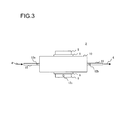
- Temperature sensors 12a and 12b are respectively installed on a cooling block entry-side pipe surface and a cooling block exit-side pipe surface of the cooling pipe 11 to measure an entry-side cooling medium temperature Tin and an exit-side cooling medium temperature Tout. It is to be noted that while the installation location of the temperature sensor 12a for measuring the entry-side cooling medium temperature Tin is desirably near a block inlet of the cooling pipe 11 that penetrates the inside of the cooling block 10, a location near the block entry-side is to suffice. In a similar manner, while the installation location of the temperature sensor 12b for measuring the exit-side cooling medium temperature Tout is desirably near a block outlet of the cooling pipe 11 that penetrates the inside of the cooling block 10, a location near the block exit-side is to suffice.
- the temperature sensors 12a and 12b may be installed near the block entry-side and the block exit-side of the cooling pipe 11 that penetrates the cooling block 10.
- a temperature sensor 12c is installed on a surface of the secondary battery 8 to measure a surface temperature Ts of the secondary battery 8. While the embodiment illustrates an example in which the surface temperature Ts of the secondary battery 8 is assumed to be a battery temperature, the battery temperature is not limited to the surface temperature of the secondary battery 8 and may instead be an internal temperature of the secondary battery 8.
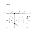
- FIG. 5 is a diagram illustrating a thermal equivalent circuit around the single secondary battery illustrated in FIGS. 3 and 4 .
- Q0 denotes an amount of heat generated by the secondary battery 8
- Rc denotes an internal thermal resistance of the secondary battery 8
- Ra denotes an atmosphere thermal resistance
- Rs denotes a thermal resistance of the thermal conductive sheet 9
- Rb denotes a thermal resistance of the cooling block 10
- Rp denotes a thermal resistance of the cooling medium 4.
- Ta denotes an ambient temperature
- Tc denotes an internal temperature of the secondary battery 8
- Ts denotes a surface temperature of the secondary battery 8
- Tin denotes a block entry-side temperature of the cooling medium 4
- Tout denotes a block exit-side temperature of the cooling medium 4.
- the battery internal thermal resistance Rc defines a thermal resistance between the inside and the surface of the secondary battery 8, and the atmosphere thermal resistance Ra defines a thermal resistance between the surface of the secondary battery 8 and surrounding air.
- the ambient temperature Ta is a temperature of air surrounding the secondary battery 8 and is treated as a voltage source in an electric circuit.
- the thermal conductive sheet thermal resistance Rs defines a thermal resistance from the surface of the secondary battery 8 via the thermal conductive sheet 9 to the surface of the cooling block 10
- the cooling block thermal resistance Rb defines a thermal resistance from the surface of the cooling block 10 that is in contact with the thermal conductive sheet 9, through the inside of the cooling block 10 and a wall of the cooling pipe 11, and to the cooling medium 4.
- the cooling medium thermal resistance Rp defines a thermal resistance of the cooling medium 4 until the cooling medium 4 releases the heat absorbed in a cooling medium circulating pathway constituted by the cooling pipe 11 and the cooling system 3.
- the amount of heat generated by battery Q0 is the amount of heat generated by the secondary battery 8 during charge and discharge, and is treated as a current source in an electric current.
- the cooling medium exit-side temperature Tout is a temperature of the cooling medium 4 on the cooling block exit-side of the cooling pipe 11 after the cooling medium 4 has absorbed heat.
- the cooling medium entry-side temperature Tin is a temperature of the cooling medium 4 cooled by the cooling system 3 and flowing into a cooling block entry-side of the pipe 11.
- the cooling medium entry-side temperature Tin can be arranged so as to be variable according to operation control of the heat exchanger 7 of the cooling system 3 and, in this case, is treated as a voltage source of in electric circuit.
- the amount of heat generated by battery Q0 first flows via the battery internal thermal resistance Rc, and subsequently splits into the amount of heat absorbed by cooling medium Q1 that is an amount of heat absorbed by the cooling medium 4 and the amount of heat discharged into atmosphere Q2 that is an amount of heat discharged into air.
- the superiority or inferiority of the cooling performance is judged based on whether or not the amount of heat generated by battery Q0 is being efficiently transferred by the cooling medium 4. In other words, it is conceivable that the higher the ratio of the amount of heat generated by battery Q0 being transferred as the amount of heat absorbed by cooling medium Q1, the greater the cooling performance.
- the battery internal thermal resistance Rc, the thermal conductive sheet thermal resistance Rs, the cooling block thermal resistance Rb, and the cooling medium thermal resistance Rp exist in a pathway through which the amount of heat absorbed by cooling medium Q1 flows. Conceivably, an increase in these thermal resistances slows down the flow of the amount of heat absorbed by cooling medium Q1 and causes the cooling performance to deteriorate.
- the thermal conductive sheet thermal resistance Rs and the cooling medium thermal resistance Rp are susceptible to deterioration or variation over time.
- an alteration of sheet material or a decrease in adhesion of the sheet surface makes it difficult for heat to be transferred from the surface of the secondary battery 8 to the cooling block 10.
- an increase in the thermal resistances can conceivably occur due to contamination of impurities into the cooling medium 4 or by a component change of the cooling medium 4, an abnormal operation of the circulating pump 5, an increase of pressure loss caused by corrosion or a form change on a surface that comes into contact with the cooling medium 4 of the pipe 11 or the like constituting the flow channel of the cooling medium 4, and a reduction in a flow rate of the cooling medium 4 caused by these above.
- temperature sensors 12a, 12b, and 12c are installed on the battery module 2 as illustrated in FIGS. 3 and 4 to measure the cooling medium entry-side temperature Tin, the cooling medium exit-side temperature Tout, and the battery surface temperature Ts. Furthermore, the right sides of expressions (2) and (4) that represent the amount of heat absorbed by cooling medium Q1 are connected by an equal sign and modified to define the coefficient ⁇ as represented by expression (6) below.
- FIGS. 6 and 7 illustrate relationships of the coefficient ⁇ with respect to cooling medium flow rate.
- the relationships have been created from results of a thermal analysis by simulation performed on a liquid-cooled battery module 2 mounted with 72 secondary batteries 8.
- surface temperature information of a single secondary battery 8 at a representative position has been adopted as the battery surface temperature Ts.
- FIG. 6 illustrates relationships of the coefficient ⁇ with respect to cooling medium flow rate when an amount of heat generation per one secondary battery 8 is set to 7 W and 20 W. These relationships correspond to cases where the amount of heat generation Q0 of the secondary battery 8 is varied.
- the coefficient ⁇ does not include the amount of heat generated by battery Q0 and therefore is not dependent on the amount of heat generated by battery Q0, and remains approximately constant even if the amount of heat generated by battery Q0 varies.
- the coefficient ⁇ tends to increase as the flow rate increases. Therefore, when the cooling medium flow rate decreases due to an abnormality in the cooling medium circulating system, the coefficient ⁇ is expected to decrease.
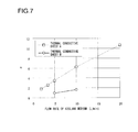
- FIG. 7 illustrates relationships between cooling medium flow rate and the coefficient ⁇ with respect to two types of thermal conductive sheets 9 having different thermal conductive properties.
- a thermal conductive sheet A represents a thermal analysis simulation performed under conditions in which a thermal conductivity of 1 W/m ⁇ K and a sheet thickness of 1.0 mm are respectively set
- a thermal conductive sheet B represents a thermal analysis simulation performed under conditions in which a thermal conductivity of 3 W/m ⁇ K and a sheet thickness of 0.1 mm are respectively set. Under these conditions, the thermal resistance Rs of the thermal conductive sheet 9 is smaller for the thermal conductive sheet B than the thermal conductive sheet A.
- the coefficient ⁇ is greater for the thermal conductive sheet A than the thermal conductive sheet B.
- the coefficient ⁇ is expected to increase.
- the temperature sensors 12a, 12b, and 12c on the battery module 2 to measure the cooling medium entry-side temperature Tin, the cooling medium exit-side temperature Tout, and the battery surface temperature Ts, and calculating the coefficient ⁇ and comparing the coefficient ⁇ with a coefficient ⁇ in previous history, a state of the cooling performance of the battery module 2 can be accurately detected and the cooling performance of the battery module 2 can be accurately judged.
- a state of the cooling performance of the battery module 2 can be accurately detected and the cooling performance of the battery module 2 can be accurately judged.
- the coefficient ⁇ is not dependent on the amount of heat generation Q0 of the secondary battery 8, the cooling performance can be detected and judged regardless of the load or operating state of the storage battery system 1.
- the thermal conductive sheet 9 is sandwiched between the secondary battery 8 and the cooling block 10 has been described as illustrated in FIGS. 3 to 5 .
- the secondary battery 8 is structured such that the surface thereof does not have a potential
- the secondary battery 8 and the cooling block 10 may be directly bonded, metal against metal, to each other in a thermal bonding without sandwiching the thermal conductive sheet 9.
- the secondary battery 8 and the cooling block 10 may be welded to each other or mechanically connected with each other by fastening using a bracket or a screw.
- the control system comprises a controller 13, a memory 14, an indicator 15, a pump control signal 16, a heat exchanger control signal 17, indication information 18, a cooling medium entry-side temperature signal STin, a cooling medium exit-side temperature signal STout, a battery surface temperature signal STs, and the like.
- the controller 13 is constituted by a microcomputer including an interface such as an AD converter and controls arithmetic processing and input/output of information and signals.
- the memory 14 stores an initial value and historical values of the coefficient ⁇ .
- the indicator 15 is a device such as a display, a lamp, a speaker, or the like that visually or auditorily informs a state of the cooling performance.
- the pump control signal 16 is a signal for controlling a motor rotation speed or the like of the circulating pump 5
- the heat exchanger control signal 17 is a signal for controlling operations of the heat exchanger 7.
- indication information 18 is information to be indicated on the indicator 15.
- the cooling medium entry-side temperature signal STin, the cooling medium exit-side temperature signal STout, and the battery surface temperature signal STs are respectively outputs of the temperature sensors 12a, 12b, and 12c in the battery module 2 illustrated in FIGS. 3 and 4 .
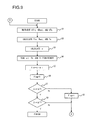
- FIG. 9 is a flow chart illustrating an example of a process for measuring and judging the cooling performance.
- the controller 13 retrieves the cooling medium entry-side temperature signal STin, the cooling medium exit-side temperature signal STout, and the battery surface temperature signal STs from the sensors 12a, 12b, and 12c, and reads a voltage value or a current value of these signals.
- the controller 13 obtains a cooling medium entry-side temperature Tin, a cooling medium exit-side temperature Tout, and a battery surface temperature Ts based on the signals STin, STout, and STs from the sensors 12a, 12b, and 12c.
- step 4 the controller 13 reads a coefficient historical value ⁇ i of the coefficient ⁇ stored in the memory 14, and in step 5, the controller 13 compares the coefficient ⁇ with the coefficient historical value ⁇ i and obtains a difference ⁇ .
- step 6 the controller 13 sets a flag "Flag" that denotes an abnormal state of the cooling performance to 0.
- step 7 the controller 13 reads an upper limit threshold Th set in advance from the memory 14 and compares the difference ⁇ with the upper limit threshold Th. When the difference ⁇ is equal to or lower than the upper limit threshold Th, the controller 13 judges that the cooling performance is normal and proceeds to step 9. Otherwise, the controller 13 judges that the cooling performance is abnormal and proceeds to step 8.
- step 9 the controller 13 reads a lower limit threshold T1 set in advance from the memory 14 and compares the difference ⁇ with the lower limit threshold T1. When the difference ⁇ is equal to or higher than the lower limit threshold T1, the controller 13 judges that the cooling performance is normal and ends the judgment process. Otherwise, the controller 13 judges that the cooling performance is abnormal and proceeds to step 11 in FIG. 10 (or step 11 in FIG. 11 ).
- FIG. 10 is a flow chart illustrating an example of a process when the cooling performance is judged to be abnormal by the controller 13.
- the controller 13 sets indication information 18 to be outputted to the indicator 15 according to the value of the flag "Flag” denoting an abnormal state of cooling performance.
- flag "Flag” 0
- An abnormality "A” indicates that the coefficient ⁇ has become abnormally smaller than the coefficient historical value ⁇ i using an error code or a message, an indication state of the lamp, or the like.
- an abnormality "B" indicates that the coefficient ⁇ has become abnormally greater than a coefficient initial value ⁇ 0 using an error code or a message, an indication state of the lamp, or the like by a method that differs from that of the abnormality "A”.
- An abnormality of the cooling medium circulating system is suspected in the case of the abnormality "A”
- a deterioration of the thermal conductive sheet is suspected in the case of the abnormality "B”.
- FIG. 11 is a flow chart illustrating another example of a process when the cooling performance is judged to be abnormal by the controller 13.
- the controller 13 sets indication information 18 to be outputted to the indicator 15 according to the value of the flag "Flag” denoting an abnormal state of cooling performance.
- flag "Flag” 0
- step 14 the controller 13 increases the motor rotation speed of the circulating pump 5 and controls the pump so as to increase the flow rate of the cooling medium 4. Furthermore, in step 15, the controller 13 controls the heat exchanger so as to lower a target temperature of the cooling medium 4 that is cooled by the heat exchanger 7. Subsequently, the controller 13 returns to step 1 in FIG. 9 to once again execute a calculating process of the coefficient ⁇ so that the difference ⁇ eventually falls between the upper limit threshold Th and the lower limit threshold T1.
- the controller 13 compares a measured coefficient ⁇ with a coefficient historical value ⁇ i and judges the cooling performance based on the comparison result.
- the controller 13 stores the coefficient ⁇ at predetermined time intervals from an initial value as coefficient historical values ⁇ i in the memory 14, and executes a process for detecting a tendency time-dependent variation of the coefficient historical values ⁇ i. By this detection process, the controller 13 judges whether a measured coefficient ⁇ is consistent with the variation tendency of the coefficient historical values ⁇ i or is an abrupt variation.
- FIG. 12 is a perspective view illustrating a battery module 102 of an air-cooled storage battery system 101 according to an embodiment.
- an approximately cuboid chassis block 110 internally holds a plurality of secondary batteries 108.
- the chassis block 110 is constituted by five resin or resin-molded chassis members 110a to 110e, and a plurality of cylindrical secondary batteries 108 are held within the chassis block 110.
- a cooling air inlet 110f is formed on one end in a longitudinal direction of the chassis block 110, and a cooling air outlet 110g is formed on another end of the chassis block 110.
- a cooling air passage is formed along the longitudinal direction in the chassis block 110, and the plurality of secondary batteries 108 is arranged in a single row along the cooling air passage in the chassis block 110.
- the secondary batteries 108 are arranged in a single row along the longitudinal direction of the chassis block 110 is shown in the air-cooled battery module 102 illustrated in FIG. 12 , the arrangement of the secondary batteries 108 in the chassis block 110 is not limited to this example.
- Temperature sensors 112a, 112b, 112c, and 112d are installed in the chassis block 110.
- the temperature sensor 112a is arranged near the cooling air inlet 110f of the chassis block 110 and outputs an entry-side cooling medium (in this case, cooling air) temperature signal STin.
- the temperature sensor 112b is arranged near the cooling air outlet 110g of the chassis block 110 and outputs an exit-side cooling medium (in this case, cooling air) temperature signal STout.
- the temperature sensors 112c and 112d are arranged on surfaces of two representative secondary batteries among the secondary batteries 108 held in the chassis block 110 and output surface temperature signals STs of the secondary batteries 108. Output signal lines of the sensors 112a to 112d are bundled by a harness 131 and connected to the controller 13 illustrated in FIG. 8 .
- a cooling system (corresponding to the liquid cooling-type cooling system 3 illustrated in FIG. 1 ) constituted by an air-conditioning duct and a cooling fan, not shown, is connected to the air-cooled battery module 102 illustrated in FIG. 12 , and air is blown by the cooling fan to the secondary batteries 108 in the battery module 102 through the air-conditioning duct.
- the cooling fan is controlled by a fan control signal (not shown) from the controller 13 illustrated in FIG. 8 .
- a configuration of a control system of the air-cooled battery module 102 is similar to that of the control system of the aforementioned liquid-cooled battery module 2 which is constituted by a controller, an indicator, a memory, and the like and which is illustrated in FIG. 8 , and a depiction and a description thereof will be omitted.
- a secondary battery is held by a holding member (the aforementioned cooling block, chassis block, or the like) having a flow channel (the aforementioned cooling pipe, cooling air flow channel, or the like) of a cooling medium that cools the secondary battery.
- a holding member the aforementioned cooling block, chassis block, or the like
- a flow channel the aforementioned cooling pipe, cooling air flow channel, or the like
- temperatures T1 and T2 of the cooling medium taken at two locations in the flow channel and a temperature T3 of the secondary battery are measured, a coefficient ⁇ defined as (T3 - T1)/(T2 - T1), (T3 - T2)/(T2 - T1), or (T3 - T2)/(T3 - T1) is repetitively calculated, and the cooling performance of the secondary battery is judged based on a variation of the coefficient ⁇ .
- the cooling performance of the battery cooling system can be accurately judged based on measured values and without using estimated values.
- the cooling performance of the secondary battery is judged to be abnormal when a difference between a currently calculated value and a previously calculated value of the coefficient ⁇ exceeds a range set in advance. Therefore, the cooling performance of the battery cooling system can be judged accurately.
- the cooling performance of the battery cooling system can be accurately judged even with a holding member (the aforementioned cooling block, chassis block, or the like) having a structure in which the secondary battery is held via a thermal conductive sheet.
- an abnormality of the cooling performance is judged to be caused by a failure in the thermal conductive sheet when a difference between a currently calculated value and a previously calculated value of the coefficient ⁇ exceeds a range set in advance and the currently calculated value is greater than the previously calculated value.
- an abnormality of the cooling performance is judged to be caused by a failure in a battery cooling system due to a cooling medium when a difference between a currently calculated value and a previously calculated value of the coefficient ⁇ exceeds a range set in advance and the currently calculated value is smaller than the previously calculated value. Therefore, a cause of an abnormality of the cooling performance of the battery cooling system can be identified.
- the failure of the battery cooling system can be solved.
Landscapes
- Engineering & Computer Science (AREA)
- Manufacturing & Machinery (AREA)
- Chemical & Material Sciences (AREA)
- Chemical Kinetics & Catalysis (AREA)
- Electrochemistry (AREA)
- General Chemical & Material Sciences (AREA)
- Automation & Control Theory (AREA)
- Secondary Cells (AREA)
Abstract
Description
- The disclosure of the following priority application is herein incorporated by reference:
- Japanese Patent Application No.
2010-102610 filed April 27, 2010 - The present invention relates to a storage battery system using a secondary battery.
- Performance and life time of a secondary battery strongly depend on the temperature of the secondary battery. Since the likelihood of deterioration increases at high temperatures, with a secondary battery system that requires a large current such as that of a hybrid vehicle, a cooling performance of a cooling system during charge and discharge must be accurately monitored. Cooling methods of secondary batteries can be divided into two methods, namely, an air-cooling method in which air is supplied by a fan to cool a secondary battery and a liquid-cooling method in which a liquid cooling medium is circulated to a secondary battery to transfer heat to the outside. Conceivable causes of degradation of a cooling performance in an air-cooling method include fan failure and accumulation of dust and extraneous matter on the secondary battery or in a draft air duct. Conceivable causes of degradation of a cooling performance in a liquid-cooling method include a failure of a pump that circulates a cooling medium, a change in components of the cooling medium, and deterioration due to metal corrosion in a cooling medium flow channel. As a technique for judging an abnormality in the cooling performance of such a secondary battery cooling system, Japanese Patent Laid-Open No.
2001-313092 - However, with the conventional storage battery system described above, since a battery temperature is estimated based on an amount of heat generation due to a charge and discharge current of a secondary battery, ambient temperature, an operating mode of a fan, a history of estimated temperatures, and the like, there is a problem in that an estimate contains error and whether or not the cooling performance of a battery cooling system is normal cannot be judged accurately.
- According to the 1st aspect of the present invention, a storage battery system comprises: a secondary battery; a holding member comprising a flow channel of a cooling medium for cooling the secondary battery, which holds the secondary battery; a medium temperature measuring means for measuring temperatures T1 and T2 of the cooling medium at two locations in the flow channel; a battery temperature measuring means for measuring a temperature T3 of the secondary battery; and/or a judging means for repetitively calculating a coefficient α and/or judging a cooling performance of the secondary battery based on a variation of the coefficient α, the coefficient α being defined as (T3 - T1)/(T2 - T1), (T3 - T2)/(T2 - T1), or (T3 - T2)/(T3 - T1).
- According to the 2nd aspect of the present invention, the judgment means of a storage battery system according to the 1st aspect may judge that the cooling performance of the secondary battery is abnormal when a difference between a currently calculated value and a previously calculated value of the coefficient α exceeds a range set in advance.
- According to the 3rd aspect of the present invention, the medium temperature measuring means of a storage battery system according to the 1st or 2nd aspect may measure temperatures T1 and T2 at an entry-side and an exit-side of the holding member of the flow channel passing through the holding member.
- According to the 4th aspect of the present invention, it is preferred that the holding member of a storage battery system according to any one of the 1st through 3rd aspects holds the secondary battery via a thermal conductive sheet.
- According to the 5th aspect of the present invention, it is preferred that in a storage battery system according to the 4th aspect, the judgment means judges that an abnormality of the cooling performance is caused by a failure in the thermal conductive sheet when a difference between a currently calculated value and a previously calculated value of the coefficient α exceeds a range set in advance and/or the currently calculated value is greater than the previously calculated value.
- According to the 6th aspect of the present invention, it is preferred that in a storage battery system according to any one of the 1st through 5th aspects, the judgment means judges that an abnormality of the cooling performance is caused by a failure in a cooling system of the secondary battery due to the cooling medium when a difference between a currently calculated value and a previously calculated value of the coefficient α exceeds a range set in advance and/or the currently calculated value is smaller than the previously calculated value.
- According to the 7th aspect of the present invention, the judgment means of a storage battery system according to the 6th aspect may increase the cooling performance of the cooling system when a failure of the cooling system of the secondary battery due to the cooling medium is judged.
- According to the present invention, a cooling performance of a battery cooling system can be judged accurately.
-
-
FIG. 1 is a diagram illustrating a configuration of a liquid-cooled storage battery system according to an embodiment; -
FIG. 2 is a diagram illustrating a partial configuration of a battery module illustrated inFIG. 1 ; -
FIG. 3 is a side view illustrating, in enlargement, a portion of a single secondary battery of the battery module illustrated inFIG. 2 ; -
FIG. 4 is a top view illustrating, in enlargement, a portion of a single secondary battery of the battery module illustrated inFIG. 2 ; -
FIG. 5 is a diagram illustrating a thermal equivalent circuit around the single secondary battery illustrated inFIGS. 3 and4 ; -
FIG. 6 is a diagram illustrating relationships of a coefficient α with respect to a cooling medium flow rate when an amount of heat generated per one secondary battery is set to 7 W and 20 W; -
FIG. 7 is a diagram illustrating relationships of a coefficient α with respect to a cooling medium flow rate in two types of thermal conductive sheets having different thermal conductive properties; -
FIG. 8 is a diagram illustrating a configuration of a control system of a storage battery system according to an embodiment; -
FIG. 9 is a flow chart illustrating an example of a process for performing measurement and judgment of cooling performance; -
FIG. 10 is a flow chart illustrating an example of a process when cooling performance is judged to be abnormal; -
FIG. 11 is a flow chart illustrating another example of a process when cooling performance is judged to be abnormal; and -
FIG. 12 is a perspective view illustrating a battery module of an air-cooled storage battery system according to an embodiment. -
-
FIG. 1 illustrates a configuration of a liquid-cooled storage battery system according to an embodiment. Astorage battery system 1 according to the embodiment comprises abattery module 2, acooling system 3, acooling medium 4, and the like. Thecooling system 3 circulates thecooling medium 4 to thebattery module 2. Thecooling medium 4 absorbs heat generated by thebattery module 2 and transfers the heat to the outside of thebattery module 2. For example, water, an antifreeze liquid, or the like can be used as thecooling medium 4. The liquid-coolingtype cooling system 3 comprises a circulatingpump 5, atank 6, aheat exchanger 7, and the like. The circulatingpump 5 supplies kinetic energy to thecooling medium 4 for sending thecooling medium 4 to thebattery module 2. Thetank 6 stores thecooling medium 4 to be circulated and supplies thecooling medium 4 to the circulatingpump 5. Theheat exchanger 7 cools thecooling medium 4 that has been reclaimed after absorbing the heat of thebattery module 2 by heat exchange with the outside, and stores thecooling medium 4 in thetank 6. -
FIG. 2 illustrates a partial configuration of thebattery module 2. In thebattery module 2, a plurality ofsecondary batteries 8 is covered by a thermalconductive sheet 9 and held by acooling block 10. WhileFIG. 2 illustrates a part of thebattery module 2 in which sixsecondary batteries 8 are held by thecooling block 10, a large number ofsecondary batteries 8 are further built into thebattery module 2 by similar structures. Acooling pipe 11 for passing thecooling medium 4 penetrates the inside of thecooling block 10. Moreover, whileFIG. 2 illustrates an example in which thecooling pipe 11 splits into two branches at an entry-side of the inside of thecooling block 10 and converges at an exit side, a configuration and a method of piping of thecooling pipe 11 inside thecooling block 10 are not limited to those illustrated inFIG. 2 . -
FIGS. 3 and4 illustrate an enlarged portion of a single secondary battery of thebattery module 2, whereinFIG. 3 is a side view andFIG. 4 is a top view. The cylindricalsecondary battery 8 is covered by the thermalconductive sheet 9 and held by thecooling block 10. Thecooling pipe 11 for passing thecooling medium 4 is laid out inside thecooling block 10. The shape of thesecondary battery 8 is not limited to a cylindrical shape and may be another shape such as a square or laminated shape. - Heat generated by the
secondary battery 8 during charge and discharge is primarily transferred via the thermalconductive sheet 9 surrounding a circumference of a side surface of thesecondary battery 8 and via thecooling block 10, and is absorbed by thecooling medium 4 that flows through thecooling pipe 11. The thermalconductive sheet 9 has a thickness of around 1 mm, features superior insulating performance and thermal conductivity in a thickness direction, has high sheet surface adhesion, and facilitates heat transfer while insulating thesecondary battery 8 and thecooling block 10 from each other. Moreover, with a secondary battery structured such that a surface of the secondary battery does not have a potential and the battery surface may come into direct contact with thecooling block 10 without causing any problems, the insulating performance of the thermalconductive sheet 9 is not a requisite, and a structure may be adopted in which thesecondary battery 8 is brought into direct contact with and held by thecooling block 10 without using the thermalconductive sheet 9. Thecooling block 10 is formed of a metal with high thermal conductivity such as aluminum. In addition, thecooling pipe 11 is also metallic and penetrates the inside of thecooling block 10. -
Temperature sensors cooling pipe 11 to measure an entry-side cooling medium temperature Tin and an exit-side cooling medium temperature Tout. It is to be noted that while the installation location of thetemperature sensor 12a for measuring the entry-side cooling medium temperature Tin is desirably near a block inlet of thecooling pipe 11 that penetrates the inside of thecooling block 10, a location near the block entry-side is to suffice. In a similar manner, while the installation location of thetemperature sensor 12b for measuring the exit-side cooling medium temperature Tout is desirably near a block outlet of thecooling pipe 11 that penetrates the inside of thecooling block 10, a location near the block exit-side is to suffice. It is to be noted that in thebattery module 2 where a plurality ofsecondary batteries 8 is held by asingle cooling block 10 as illustrated inFIG. 2 , thetemperature sensors cooling pipe 11 that penetrates thecooling block 10. - In addition, a
temperature sensor 12c is installed on a surface of thesecondary battery 8 to measure a surface temperature Ts of thesecondary battery 8. While the embodiment illustrates an example in which the surface temperature Ts of thesecondary battery 8 is assumed to be a battery temperature, the battery temperature is not limited to the surface temperature of thesecondary battery 8 and may instead be an internal temperature of thesecondary battery 8. -
FIG. 5 is a diagram illustrating a thermal equivalent circuit around the single secondary battery illustrated inFIGS. 3 and4 . InFIG. 5 , Q0 denotes an amount of heat generated by thesecondary battery 8, Rc denotes an internal thermal resistance of thesecondary battery 8, Ra denotes an atmosphere thermal resistance, Rs denotes a thermal resistance of the thermalconductive sheet 9, Rb denotes a thermal resistance of thecooling block 10, and Rp denotes a thermal resistance of thecooling medium 4. In addition, as temperatures of each node of the thermal equivalent circuit, Ta denotes an ambient temperature, Tc denotes an internal temperature of thesecondary battery 8, Ts denotes a surface temperature of thesecondary battery 8, Tin denotes a block entry-side temperature of thecooling medium 4, and Tout denotes a block exit-side temperature of thecooling medium 4. Furthermore, an amount of heat absorbed by cooling medium Q1 and amount of heat discharged into atmosphere Q2 indicating a flow of heat are defined. - The respective parameters of the thermal equivalent circuit illustrated in
FIG. 5 will be described in detail. The battery internal thermal resistance Rc defines a thermal resistance between the inside and the surface of thesecondary battery 8, and the atmosphere thermal resistance Ra defines a thermal resistance between the surface of thesecondary battery 8 and surrounding air. The ambient temperature Ta is a temperature of air surrounding thesecondary battery 8 and is treated as a voltage source in an electric circuit. In addition, the thermal conductive sheet thermal resistance Rs defines a thermal resistance from the surface of thesecondary battery 8 via the thermalconductive sheet 9 to the surface of thecooling block 10, and the cooling block thermal resistance Rb defines a thermal resistance from the surface of thecooling block 10 that is in contact with the thermalconductive sheet 9, through the inside of thecooling block 10 and a wall of the coolingpipe 11, and to thecooling medium 4. The cooling medium thermal resistance Rp defines a thermal resistance of the cooling medium 4 until the cooling medium 4 releases the heat absorbed in a cooling medium circulating pathway constituted by the coolingpipe 11 and thecooling system 3. - The amount of heat generated by battery Q0 is the amount of heat generated by the
secondary battery 8 during charge and discharge, and is treated as a current source in an electric current. The cooling medium exit-side temperature Tout is a temperature of the cooling medium 4 on the cooling block exit-side of the coolingpipe 11 after thecooling medium 4 has absorbed heat. In addition, the cooling medium entry-side temperature Tin is a temperature of the cooling medium 4 cooled by thecooling system 3 and flowing into a cooling block entry-side of thepipe 11. The cooling medium entry-side temperature Tin can be arranged so as to be variable according to operation control of theheat exchanger 7 of thecooling system 3 and, in this case, is treated as a voltage source of in electric circuit. - The amount of heat generated by battery Q0 first flows via the battery internal thermal resistance Rc, and subsequently splits into the amount of heat absorbed by cooling medium Q1 that is an amount of heat absorbed by the cooling
medium 4 and the amount of heat discharged into atmosphere Q2 that is an amount of heat discharged into air. In other words, the amount of heat generated by battery Q0 can be expressed as
- As is obvious from the thermal equivalent circuit illustrated in
FIG. 5 , the amount of heat absorbed by cooling medium Q1 can be expressed as


- In addition, the amount of heat discharged into atmosphere Q2 can be expressed as

- Next, a method of judging deterioration of a cooling performance will be described. The superiority or inferiority of the cooling performance is judged based on whether or not the amount of heat generated by battery Q0 is being efficiently transferred by the cooling
medium 4. In other words, it is conceivable that the higher the ratio of the amount of heat generated by battery Q0 being transferred as the amount of heat absorbed by cooling medium Q1, the greater the cooling performance. As illustrated inFIG. 5 , the battery internal thermal resistance Rc, the thermal conductive sheet thermal resistance Rs, the cooling block thermal resistance Rb, and the cooling medium thermal resistance Rp exist in a pathway through which the amount of heat absorbed by cooling medium Q1 flows. Conceivably, an increase in these thermal resistances slows down the flow of the amount of heat absorbed by cooling medium Q1 and causes the cooling performance to deteriorate. - Among the thermal resistances in the pathway through which the amount of heat absorbed by cooling medium Q1 flows, the thermal conductive sheet thermal resistance Rs and the cooling medium thermal resistance Rp are susceptible to deterioration or variation over time. With the thermal conductive sheet thermal resistance Rs, an alteration of sheet material or a decrease in adhesion of the sheet surface makes it difficult for heat to be transferred from the surface of the
secondary battery 8 to thecooling block 10. In addition, with the cooling medium thermal resistance Rp, an increase in the thermal resistances can conceivably occur due to contamination of impurities into the cooling medium 4 or by a component change of thecooling medium 4, an abnormal operation of the circulatingpump 5, an increase of pressure loss caused by corrosion or a form change on a surface that comes into contact with the coolingmedium 4 of thepipe 11 or the like constituting the flow channel of thecooling medium 4, and a reduction in a flow rate of the cooling medium 4 caused by these above. - In consideration thereof, with the
storage battery system 1 according to an embodiment, in order to detect variations in the thermal conductive sheet thermal resistance Rs and the cooling medium thermal resistance Rp,temperature sensors battery module 2 as illustrated inFIGS. 3 and4 to measure the cooling medium entry-side temperature Tin, the cooling medium exit-side temperature Tout, and the battery surface temperature Ts. Furthermore, the right sides of expressions (2) and (4) that represent the amount of heat absorbed by cooling medium Q1 are connected by an equal sign and modified to define the coefficient α as represented by expression (6) below.
- The coefficient α can be calculated based on measured values of the cooling medium entry-side temperature Tin, the cooling medium exit-side temperature Tout, and the battery surface temperature Ts. Since coefficient α = (Rs + Rb + Rp)/Rp, an increase in the thermal conductive sheet thermal resistance Rs due to an abnormality of the thermal
conductive sheet 9 is manifested as an increase of the coefficient α. In addition, an increase in the cooling medium thermal resistance Rp due to an abnormality of the cooling medium circulating system is manifested as a decrease of the coefficient α. -
FIGS. 6 and7 illustrate relationships of the coefficient α with respect to cooling medium flow rate. The relationships have been created from results of a thermal analysis by simulation performed on a liquid-cooledbattery module 2 mounted with 72secondary batteries 8. In addition, surface temperature information of a singlesecondary battery 8 at a representative position has been adopted as the battery surface temperature Ts. Referring to the drawings, variations in the coefficient α due to abnormalities of the thermalconductive sheet 9 and the cooling medium circulating system will be described. -
FIG. 6 illustrates relationships of the coefficient α with respect to cooling medium flow rate when an amount of heat generation per onesecondary battery 8 is set to 7 W and 20 W. These relationships correspond to cases where the amount of heat generation Q0 of thesecondary battery 8 is varied. As represented by the expression (6) above, the coefficient α does not include the amount of heat generated by battery Q0 and therefore is not dependent on the amount of heat generated by battery Q0, and remains approximately constant even if the amount of heat generated by battery Q0 varies. However, the coefficient α tends to increase as the flow rate increases. Therefore, when the cooling medium flow rate decreases due to an abnormality in the cooling medium circulating system, the coefficient α is expected to decrease. -
FIG. 7 illustrates relationships between cooling medium flow rate and the coefficient α with respect to two types of thermalconductive sheets 9 having different thermal conductive properties. A thermal conductive sheet A represents a thermal analysis simulation performed under conditions in which a thermal conductivity of 1 W/m·K and a sheet thickness of 1.0 mm are respectively set, and a thermal conductive sheet B represents a thermal analysis simulation performed under conditions in which a thermal conductivity of 3 W/m·K and a sheet thickness of 0.1 mm are respectively set. Under these conditions, the thermal resistance Rs of the thermalconductive sheet 9 is smaller for the thermal conductive sheet B than the thermal conductive sheet A. When comparing both thermal conductive sheets at the same flow rate of thecooling medium 4, the coefficient α is greater for the thermal conductive sheet A than the thermal conductive sheet B. In other words, in a case where the thermal resistance Rs increases due to an abnormality of the thermalconductive sheet 9, the coefficient α is expected to increase. - As described above, by installing the
temperature sensors battery module 2 to measure the cooling medium entry-side temperature Tin, the cooling medium exit-side temperature Tout, and the battery surface temperature Ts, and calculating the coefficient α and comparing the coefficient α with a coefficient α in previous history, a state of the cooling performance of thebattery module 2 can be accurately detected and the cooling performance of thebattery module 2 can be accurately judged. In addition, according to an increase/decrease of the calculated coefficient α, whether a reduction in cooling performance is due to thecooling system 3 by the cooling medium 4 or to an abnormality of the thermalconductive sheet 9 can be identified. Furthermore, since the coefficient α is not dependent on the amount of heat generation Q0 of thesecondary battery 8, the cooling performance can be detected and judged regardless of the load or operating state of thestorage battery system 1. - In the embodiment described above, as represented by the expression (6), an example has been illustrated where the coefficient α is defined as a ratio between (Ts - Tin) and (Tout - Tin). However, as represented by the expression (3) above, since the amount of heat absorbed by cooling medium Q1 can also be expressed using (Ts - Tout), two coefficients α' and α" expressed the expressions (7) and (8) as follows can be obtained, and even when the aforementioned coefficient α is replaced with the coefficients α' and α", an index may be obtained for detecting an increase in the thermal conductive sheet thermal resistance Rs or the cooling medium thermal resistance Rp.


- In addition, in the above embodiment, an example in which the thermal
conductive sheet 9 is sandwiched between thesecondary battery 8 and thecooling block 10 has been described as illustrated inFIGS. 3 to 5 . However, in a case where thesecondary battery 8 is structured such that the surface thereof does not have a potential, thesecondary battery 8 and thecooling block 10 may be directly bonded, metal against metal, to each other in a thermal bonding without sandwiching the thermalconductive sheet 9. For example, conceivably, thesecondary battery 8 and thecooling block 10 may be welded to each other or mechanically connected with each other by fastening using a bracket or a screw. - In a case where the
secondary battery 8 is directly held by thecooling block 10, the thermal conductive sheet thermal resistance Rs of the thermal equivalent circuit illustrated inFIG. 5 can be omitted, whereby the coefficient α may be expressed as
- Accordingly, even when the thermal
conductive sheet 9 is not present, in the same manner as the embodiment described above, an increase of the cooling medium thermal resistance Rp is manifested as a decrease in the coefficient α and an abnormality in the cooling medium circulating system can be detected. - Next, a configuration of a control system of the
storage battery system 1 according to an embodiment will be described with reference toFIG. 8 . Besides the components of the cooling system of thestorage battery system 1 illustrated inFIG. 1 , the control system comprises acontroller 13, amemory 14, anindicator 15, apump control signal 16, a heatexchanger control signal 17,indication information 18, a cooling medium entry-side temperature signal STin, a cooling medium exit-side temperature signal STout, a battery surface temperature signal STs, and the like. Thecontroller 13 is constituted by a microcomputer including an interface such as an AD converter and controls arithmetic processing and input/output of information and signals. Thememory 14 stores an initial value and historical values of the coefficient α. Theindicator 15 is a device such as a display, a lamp, a speaker, or the like that visually or auditorily informs a state of the cooling performance. - The
pump control signal 16 is a signal for controlling a motor rotation speed or the like of the circulatingpump 5, and the heatexchanger control signal 17 is a signal for controlling operations of theheat exchanger 7. In addition,indication information 18 is information to be indicated on theindicator 15. The cooling medium entry-side temperature signal STin, the cooling medium exit-side temperature signal STout, and the battery surface temperature signal STs are respectively outputs of thetemperature sensors battery module 2 illustrated inFIGS. 3 and4 . - A process performed by the
controller 13 to measure and judge cooling performance will be described with reference toFIGS. 9 to 11 .FIG. 9 is a flow chart illustrating an example of a process for measuring and judging the cooling performance. Instep 1, thecontroller 13 retrieves the cooling medium entry-side temperature signal STin, the cooling medium exit-side temperature signal STout, and the battery surface temperature signal STs from thesensors next step 2, thecontroller 13 obtains a cooling medium entry-side temperature Tin, a cooling medium exit-side temperature Tout, and a battery surface temperature Ts based on the signals STin, STout, and STs from thesensors step 3, thecontroller 13 calculates the coefficient α = (Ts - Tin)/(Tout - Tin) by using the cooling medium entry-side temperature Tin, the cooling medium exit-side temperature Tout, and the battery surface temperature Ts. - In
step 4, thecontroller 13 reads a coefficient historical value αi of the coefficient α stored in thememory 14, and instep 5, thecontroller 13 compares the coefficient α with the coefficient historical value αi and obtains a difference Δα. Instep 6, thecontroller 13 sets a flag "Flag" that denotes an abnormal state of the cooling performance to 0. Instep 7, thecontroller 13 reads an upper limit threshold Th set in advance from thememory 14 and compares the difference Δα with the upper limit threshold Th. When the difference Δα is equal to or lower than the upper limit threshold Th, thecontroller 13 judges that the cooling performance is normal and proceeds to step 9. Otherwise, thecontroller 13 judges that the cooling performance is abnormal and proceeds to step 8. When thecontroller 13 judges that the cooling performance is abnormal, thecontroller 13 sets the flag "Flag" to 1 instep 8 and proceeds to step 11 inFIG. 10 (or step 11 inFIG. 11 ). On the other hand, when thecontroller 13 judges that the cooling performance is normal, instep 9, thecontroller 13 reads a lower limit threshold T1 set in advance from thememory 14 and compares the difference Δα with the lower limit threshold T1. When the difference Δα is equal to or higher than the lower limit threshold T1, thecontroller 13 judges that the cooling performance is normal and ends the judgment process. Otherwise, thecontroller 13 judges that the cooling performance is abnormal and proceeds to step 11 inFIG. 10 (or step 11 inFIG. 11 ). -
FIG. 10 is a flow chart illustrating an example of a process when the cooling performance is judged to be abnormal by thecontroller 13. Instep 11, thecontroller 13sets indication information 18 to be outputted to theindicator 15 according to the value of the flag "Flag" denoting an abnormal state of cooling performance. When flag "Flag" = 0, thecontroller 13 proceeds to step 12 to indicate an abnormality "A" on theindicator 15, and when flag "Flag" = 1, thecontroller 13 proceeds to step 13 to indicate an abnormality "B" on theindicator 15. An abnormality "A" indicates that the coefficient α has become abnormally smaller than the coefficient historical value αi using an error code or a message, an indication state of the lamp, or the like. On the other hand, an abnormality "B" indicates that the coefficient α has become abnormally greater than a coefficient initial value α0 using an error code or a message, an indication state of the lamp, or the like by a method that differs from that of the abnormality "A". An abnormality of the cooling medium circulating system is suspected in the case of the abnormality "A", and a deterioration of the thermal conductive sheet is suspected in the case of the abnormality "B". -
FIG. 11 is a flow chart illustrating another example of a process when the cooling performance is judged to be abnormal by thecontroller 13. Instep 11, thecontroller 13sets indication information 18 to be outputted to theindicator 15 according to the value of the flag "Flag" denoting an abnormal state of cooling performance. When flag "Flag" = 0, thecontroller 13 proceeds to step 12 to indicate the abnormality "A" on theindicator 15, and when flag "Flag" = 1, thecontroller 13 proceeds to step 13 to indicate the abnormality "B" on theindicator 15. Since an abnormality of the cooling medium circulating system is suspected in the case of the abnormality "A", depending on the degree of the abnormality, changing operations of the circulatingpump 5 or theheat exchanger 7 may suffice as a countermeasure. Therefore, instep 14, thecontroller 13 increases the motor rotation speed of the circulatingpump 5 and controls the pump so as to increase the flow rate of thecooling medium 4. Furthermore, instep 15, thecontroller 13 controls the heat exchanger so as to lower a target temperature of the cooling medium 4 that is cooled by theheat exchanger 7. Subsequently, thecontroller 13 returns to step 1 inFIG. 9 to once again execute a calculating process of the coefficient α so that the difference Δα eventually falls between the upper limit threshold Th and the lower limit threshold T1. - In the cooling performance judgment process illustrated in
FIG. 9 , an example has been presented in which thecontroller 13 compares a measured coefficient α with a coefficient historical value αi and judges the cooling performance based on the comparison result. Thecontroller 13 stores the coefficient α at predetermined time intervals from an initial value as coefficient historical values αi in thememory 14, and executes a process for detecting a tendency time-dependent variation of the coefficient historical values αi. By this detection process, thecontroller 13 judges whether a measured coefficient α is consistent with the variation tendency of the coefficient historical values αi or is an abrupt variation. When the coefficient α has varied abruptly, an occurrence of some kind of abnormality is presumed in cooling performance, whereby a cause of the abnormality can be identified as described above from an increase or decrease of the coefficient α. Accordingly, the accuracy of judgment of the cooling performance can be improved and abnormalities can be processed more precisely. - While an example of a liquid-cooled
storage battery system 1 has been described as the above embodiment of the present invention, the present invention can also be applied to an air-cooled storage battery system.FIG. 12 is a perspective view illustrating abattery module 102 of an air-cooledstorage battery system 101 according to an embodiment. In thebattery module 102 of the air-cooledstorage battery system 101, an approximatelycuboid chassis block 110 internally holds a plurality ofsecondary batteries 108. Thechassis block 110 is constituted by five resin or resin-moldedchassis members 110a to 110e, and a plurality of cylindricalsecondary batteries 108 are held within thechassis block 110. - A cooling
air inlet 110f is formed on one end in a longitudinal direction of thechassis block 110, and a coolingair outlet 110g is formed on another end of thechassis block 110. In other words, a cooling air passage is formed along the longitudinal direction in thechassis block 110, and the plurality ofsecondary batteries 108 is arranged in a single row along the cooling air passage in thechassis block 110. It is to be noted that while an example in which thesecondary batteries 108 are arranged in a single row along the longitudinal direction of thechassis block 110 is shown in the air-cooledbattery module 102 illustrated inFIG. 12 , the arrangement of thesecondary batteries 108 in thechassis block 110 is not limited to this example. -
Temperature sensors chassis block 110. Thetemperature sensor 112a is arranged near the coolingair inlet 110f of thechassis block 110 and outputs an entry-side cooling medium (in this case, cooling air) temperature signal STin. Thetemperature sensor 112b is arranged near the coolingair outlet 110g of thechassis block 110 and outputs an exit-side cooling medium (in this case, cooling air) temperature signal STout. In addition, thetemperature sensors secondary batteries 108 held in thechassis block 110 and output surface temperature signals STs of thesecondary batteries 108. Output signal lines of thesensors 112a to 112d are bundled by aharness 131 and connected to thecontroller 13 illustrated inFIG. 8 . - A cooling system (corresponding to the liquid cooling-
type cooling system 3 illustrated inFIG. 1 ) constituted by an air-conditioning duct and a cooling fan, not shown, is connected to the air-cooledbattery module 102 illustrated inFIG. 12 , and air is blown by the cooling fan to thesecondary batteries 108 in thebattery module 102 through the air-conditioning duct. The cooling fan is controlled by a fan control signal (not shown) from thecontroller 13 illustrated inFIG. 8 . A configuration of a control system of the air-cooledbattery module 102 is similar to that of the control system of the aforementioned liquid-cooledbattery module 2 which is constituted by a controller, an indicator, a memory, and the like and which is illustrated inFIG. 8 , and a depiction and a description thereof will be omitted. - With such an air-cooled
storage battery system 101, a thermal conductive sheet is no longer necessary. Measurement and judgment of a cooling performance of the air-cooledstorage battery system 101 are similar to the measurement and judgment of the liquid-cooledstorage battery system 1 with the omission of the thermal conductive sheet. - In the embodiment and the modification thereof described above, as illustrated in
FIG. 8 , examples have been presented where the cooling performances of thebattery modules controller 13 and thememory 14 provided outside of thebattery modules controller 13 and thememory 14 are provided inside thebattery modules battery modules - It is to be noted that any combination of the embodiments and the modifications thereof described above including a combination of embodiments and a combination of an embodiment and a modification is possible.
- According to the embodiments and modifications thereof described above, the following operational advantages can be gained. First, a secondary battery is held by a holding member (the aforementioned cooling block, chassis block, or the like) having a flow channel (the aforementioned cooling pipe, cooling air flow channel, or the like) of a cooling medium that cools the secondary battery. Next, temperatures T1 and T2 of the cooling medium taken at two locations in the flow channel and a temperature T3 of the secondary battery are measured, a coefficient α defined as (T3 - T1)/(T2 - T1), (T3 - T2)/(T2 - T1), or (T3 - T2)/(T3 - T1) is repetitively calculated, and the cooling performance of the secondary battery is judged based on a variation of the coefficient α. As a result, the cooling performance of the battery cooling system can be accurately judged based on measured values and without using estimated values.
- In addition, according to an embodiment and a modification thereof, the cooling performance of the secondary battery is judged to be abnormal when a difference between a currently calculated value and a previously calculated value of the coefficient α exceeds a range set in advance. Therefore, the cooling performance of the battery cooling system can be judged accurately.
- According to an embodiment and a modification thereof, temperatures Tin and Tout at an entry-side and an exit-side of the aforementioned holding member of a flow channel passing through the holding member are measured, whereby the coefficient α is calculated assuming that T1 = Tin and T2 = Tout. Therefore, the coefficient α can be calculated which enables the cooling performance of the battery cooling system to be judged accurately.
- According to an embodiment and a modification thereof, the cooling performance of the battery cooling system can be accurately judged even with a holding member (the aforementioned cooling block, chassis block, or the like) having a structure in which the secondary battery is held via a thermal conductive sheet.
- According to an embodiment and a modification thereof, an abnormality of the cooling performance is judged to be caused by a failure in the thermal conductive sheet when a difference between a currently calculated value and a previously calculated value of the coefficient α exceeds a range set in advance and the currently calculated value is greater than the previously calculated value. As a result, a cause of an abnormality of the cooling performance of the battery cooling system can be identified.
- According to an embodiment and a modification thereof, an abnormality of the cooling performance is judged to be caused by a failure in a battery cooling system due to a cooling medium when a difference between a currently calculated value and a previously calculated value of the coefficient α exceeds a range set in advance and the currently calculated value is smaller than the previously calculated value. Therefore, a cause of an abnormality of the cooling performance of the battery cooling system can be identified.
- According to an embodiment and a modification thereof, since the cooling performance of the battery cooling system is increased when a failure of the battery cooling system due to the cooling medium is judged, the failure of the battery cooling system can be solved.
- The above described embodiments are examples, and various modifications can be made without departing from the scope of the invention.
Claims (7)
- A storage battery system comprising:a secondary battery (8; 108);a holding member comprising a flow channel of a cooling medium (4) for cooling the secondary battery (8; 108), which holds the secondary battery (8; 108);a medium temperature measuring means for measuring temperatures T1 and T2 of the cooling medium (4) at two locations in the flow channel;a battery temperature measuring means for measuring a temperature T3 of the secondary battery (8; 108); anda judging means for repetitively calculating a coefficient α and judging a cooling performance of the secondary battery (8; 108) based on a variation of the coefficient α, the coefficient α being defined as (T3 - T1)/(T2 - T1), (T3 - T2)/(T2 - T1), or (T3 - T2)/(T3 - T1).
- A storage battery system according to claim 1, wherein
the judgment means judges that the cooling performance of the secondary battery (8; 108) is abnormal when a difference between a currently calculated value and a previously calculated value of the coefficient α exceeds a range set in advance. - A storage battery system according to claims 1 or 2, wherein
the medium temperature measuring means measures temperatures T1 and T2 at an entry-side and an exit-side of the holding member of the flow channel passing through the holding member. - A storage battery system according to any one of claims 1 through 3, wherein
the holding member holds the secondary battery (8) via a thermal conductive sheet (9). - A storage battery system according to claim 4, wherein
the judgment means judges that an abnormality of the cooling performance is caused by a failure in the thermal conductive sheet (9) when a difference between a currently calculated value and a previously calculated value of the coefficient α exceeds a range set in advance and the currently calculated value is greater than the previously calculated value. - A storage battery system according to any one of claims 1 through 5, wherein
the judgment means judges that an abnormality of the cooling performance is caused by a failure in a cooling system (3) of the secondary battery (8; 108) due to the cooling medium (4) when a difference between a currently calculated value and a previously calculated value of the coefficient α exceeds a range set in advance and the currently calculated value is smaller than the previously calculated value. - A storage battery system according to claim 6, wherein
the judgment means increases the cooling performance of the cooling system (3) when a failure of the cooling system (3) of the secondary battery (8; 108) due to the cooling medium (4) is judged.
Applications Claiming Priority (1)
| Application Number | Priority Date | Filing Date | Title |
|---|---|---|---|
| JP2010102610A JP5572442B2 (en) | 2010-04-27 | 2010-04-27 | Liquid-cooled power storage system |
Publications (3)
| Publication Number | Publication Date |
|---|---|
| EP2383832A2 true EP2383832A2 (en) | 2011-11-02 |
| EP2383832A3 EP2383832A3 (en) | 2013-02-27 |
| EP2383832B1 EP2383832B1 (en) | 2016-07-27 |
Family
ID=44461926
Family Applications (1)
| Application Number | Title | Priority Date | Filing Date |
|---|---|---|---|
| EP11160365.0A Active EP2383832B1 (en) | 2010-04-27 | 2011-03-30 | Storage battery system |
Country Status (3)
| Country | Link |
|---|---|
| US (1) | US9425490B2 (en) |
| EP (1) | EP2383832B1 (en) |
| JP (1) | JP5572442B2 (en) |
Cited By (1)
| Publication number | Priority date | Publication date | Assignee | Title |
|---|---|---|---|---|
| WO2019052750A1 (en) * | 2017-09-13 | 2019-03-21 | Bayerische Motoren Werke Aktiengesellschaft | METHOD FOR MONITORING THE FUNCTIONALITY OF THE COOLING SYSTEM OF A HIGH-VOLTAGE MEMORY |
Families Citing this family (11)
| Publication number | Priority date | Publication date | Assignee | Title |
|---|---|---|---|---|
| US9168844B2 (en) * | 2012-07-30 | 2015-10-27 | GM Global Technology Operations LLC | Methods and systems for diagnosing performance of active cooling system in an electric vehicle |
| US9415700B2 (en) | 2012-09-04 | 2016-08-16 | GM Global Technology Operations LLC | Battery thermal system and diagnostic method |
| WO2014118911A1 (en) | 2013-01-30 | 2014-08-07 | 三菱電機株式会社 | Battery monitoring device, power storage system, and control system |
| US10249921B2 (en) * | 2013-05-23 | 2019-04-02 | Elwha Llc | Fast thermal dumping for batteries |
| KR101778675B1 (en) * | 2014-10-07 | 2017-09-14 | 주식회사 엘지화학 | Battery Pack Having Separable Temperature Sensor for Sensing The Temperature of Coolant |
| EP3205396B1 (en) | 2014-10-09 | 2020-04-29 | Toray Industries, Inc. | Photochemical reaction device, photochemical reaction method using same, and lactam production method for using said method |
| EP4567970A3 (en) * | 2016-12-27 | 2026-01-21 | Mitsubishi Chemical Corporation | Partition member, assembled battery, and heat transmission control method for assembled battery |
| CN108172930B (en) * | 2017-12-26 | 2020-05-22 | 智车优行科技(上海)有限公司 | Battery pack cooling control method and device and battery pack |
| WO2020004929A1 (en) * | 2018-06-29 | 2020-01-02 | 한국과학기술원 | Thermoelectric cooling method and device |
| CN111384466B (en) * | 2018-12-29 | 2020-12-08 | 广州汽车集团股份有限公司 | A method and system for handling water pump faults in a power battery thermal management system |
| US11901533B2 (en) * | 2021-06-02 | 2024-02-13 | Caterpillar Inc. | Sealed battery module with cooling and heating |
Citations (2)
| Publication number | Priority date | Publication date | Assignee | Title |
|---|---|---|---|---|
| JP2001313092A (en) | 2000-05-01 | 2001-11-09 | Toyota Motor Corp | Cooling device for secondary battery |
| JP2010102610A (en) | 2008-10-27 | 2010-05-06 | Sony Corp | Information processing apparatus and heat radiation method |
Family Cites Families (10)
| Publication number | Priority date | Publication date | Assignee | Title |
|---|---|---|---|---|
| JP3518198B2 (en) * | 1996-09-30 | 2004-04-12 | 松下電器産業株式会社 | Battery charging control system |
| JP3569152B2 (en) * | 1998-10-15 | 2004-09-22 | 株式会社マキタ | battery pack |
| JP4435327B2 (en) * | 1999-05-14 | 2010-03-17 | パナソニック株式会社 | Charge control device for battery pack |
| DE10223782B4 (en) * | 2002-05-29 | 2005-08-25 | Daimlerchrysler Ag | Battery with at least one electrochemical storage cell and a cooling device and use of a battery |
| JP2005293971A (en) * | 2004-03-31 | 2005-10-20 | Sanyo Electric Co Ltd | Power source device with battery |
| DE102005017648B4 (en) * | 2005-04-15 | 2008-01-10 | Daimlerchrysler Ag | Liquid cooled battery and method of operating such |
| DE602006009687D1 (en) * | 2005-11-08 | 2009-11-19 | Byd Co Ltd | HEAT LIGHTING DEVICE FOR A BATTERY PACK AND BATTERY PACK THEREWITH |
| JP5015649B2 (en) * | 2007-04-13 | 2012-08-29 | 本田技研工業株式会社 | Battery and electrical equipment cooling structure |
| US8409743B2 (en) * | 2007-11-28 | 2013-04-02 | Sanyo Electric Co., Ltd. | Battery system with battery cells arranged in array alignment |
| JP5244513B2 (en) * | 2008-09-11 | 2013-07-24 | 三洋電機株式会社 | Battery pack |
-
2010
- 2010-04-27 JP JP2010102610A patent/JP5572442B2/en active Active
-
2011
- 2011-03-30 EP EP11160365.0A patent/EP2383832B1/en active Active
- 2011-03-31 US US13/076,556 patent/US9425490B2/en active Active
Patent Citations (2)
| Publication number | Priority date | Publication date | Assignee | Title |
|---|---|---|---|---|
| JP2001313092A (en) | 2000-05-01 | 2001-11-09 | Toyota Motor Corp | Cooling device for secondary battery |
| JP2010102610A (en) | 2008-10-27 | 2010-05-06 | Sony Corp | Information processing apparatus and heat radiation method |
Cited By (2)
| Publication number | Priority date | Publication date | Assignee | Title |
|---|---|---|---|---|
| WO2019052750A1 (en) * | 2017-09-13 | 2019-03-21 | Bayerische Motoren Werke Aktiengesellschaft | METHOD FOR MONITORING THE FUNCTIONALITY OF THE COOLING SYSTEM OF A HIGH-VOLTAGE MEMORY |
| US11631910B2 (en) | 2017-09-13 | 2023-04-18 | Bayerische Motoren Werke Aktiengesellschaft | Method for monitoring the functional capability of the cooling system of a high-voltage accumulator |
Also Published As
| Publication number | Publication date |
|---|---|
| US9425490B2 (en) | 2016-08-23 |
| JP5572442B2 (en) | 2014-08-13 |
| EP2383832A3 (en) | 2013-02-27 |
| US20110262784A1 (en) | 2011-10-27 |
| JP2011233366A (en) | 2011-11-17 |
| EP2383832B1 (en) | 2016-07-27 |
Similar Documents
| Publication | Publication Date | Title |
|---|---|---|
| EP2383832B1 (en) | Storage battery system | |
| JP4591246B2 (en) | Power converter | |
| US7330046B2 (en) | Circuits and methods for failure prediction of parallel MOSFETs | |
| US9415700B2 (en) | Battery thermal system and diagnostic method | |
| US20110298472A1 (en) | Battery connection failure detection system | |
| KR102031368B1 (en) | Fault diagnosis device and method for the cooling system of construction machinery | |
| EP2437339A1 (en) | Secondary battery system for detecting distribution of heat generation | |
| CN111033873A (en) | Power storage system and management device | |
| JP6999860B2 (en) | Power converter | |
| CN105914415B (en) | Temperature monitoring device and power supply device | |
| US20230282897A1 (en) | Battery module preventing thermal runway | |
| KR20160091002A (en) | Safety control method and apparatus of the cooling-water heating type heater | |
| US12416688B2 (en) | Method to assess the ageing of an electrical connection installed in a vehicle | |
| CA2706503C (en) | A battery connection failure detection system | |
| CN111989816A (en) | Method for determining the status of a thermal connection of at least one component within an electrical energy storage system to a heat source or heat sink | |
| JP2021153008A (en) | Heat chain monitoring device | |
| JP2019149235A (en) | Power supply apparatus | |
| JP6119647B2 (en) | Electric vehicle | |
| CN118519415A (en) | Diagnostic method, control device and storage medium for cooling capacity of electric drive system | |
| JP2019187030A (en) | Power conversion apparatus | |
| JP2020064810A (en) | Cooling system | |
| JP5955213B2 (en) | Battery module | |
| JP2013011179A (en) | Abnormal condition detection device | |
| CN113454738B (en) | Power transformer assembly, method for determining the thermal state of a power transformer and determination device | |
| JP7380187B2 (en) | power converter |
Legal Events
| Date | Code | Title | Description |
|---|---|---|---|
| 17P | Request for examination filed |
Effective date: 20110801 |
|
| AK | Designated contracting states |
Kind code of ref document: A2 Designated state(s): AL AT BE BG CH CY CZ DE DK EE ES FI FR GB GR HR HU IE IS IT LI LT LU LV MC MK MT NL NO PL PT RO RS SE SI SK SM TR |
|
| AX | Request for extension of the european patent |
Extension state: BA ME |
|
| PUAI | Public reference made under article 153(3) epc to a published international application that has entered the european phase |
Free format text: ORIGINAL CODE: 0009012 |
|
| PUAL | Search report despatched |
Free format text: ORIGINAL CODE: 0009013 |
|
| AK | Designated contracting states |
Kind code of ref document: A3 Designated state(s): AL AT BE BG CH CY CZ DE DK EE ES FI FR GB GR HR HU IE IS IT LI LT LU LV MC MK MT NL NO PL PT RO RS SE SI SK SM TR |
|
| AX | Request for extension of the european patent |
Extension state: BA ME |
|
| RIC1 | Information provided on ipc code assigned before grant |
Ipc: H01M 10/50 20060101ALI20130124BHEP Ipc: H01M 10/48 20060101AFI20130124BHEP |
|
| 17Q | First examination report despatched |
Effective date: 20140123 |
|
| RAP1 | Party data changed (applicant data changed or rights of an application transferred) |
Owner name: HITACHI AUTOMOTIVE SYSTEMS, LTD. |
|
| GRAP | Despatch of communication of intention to grant a patent |
Free format text: ORIGINAL CODE: EPIDOSNIGR1 |
|
| RIC1 | Information provided on ipc code assigned before grant |
Ipc: H01M 10/6554 20140101ALI20160203BHEP Ipc: H01M 10/48 20060101AFI20160203BHEP Ipc: H01M 10/6568 20140101ALI20160203BHEP Ipc: H01M 10/633 20140101ALI20160203BHEP Ipc: H01M 10/6563 20140101ALN20160203BHEP Ipc: H01M 10/613 20140101ALI20160203BHEP |
|
| INTG | Intention to grant announced |
Effective date: 20160219 |
|
| GRAS | Grant fee paid |
Free format text: ORIGINAL CODE: EPIDOSNIGR3 |
|
| GRAA | (expected) grant |
Free format text: ORIGINAL CODE: 0009210 |
|
| AK | Designated contracting states |
Kind code of ref document: B1 Designated state(s): AL AT BE BG CH CY CZ DE DK EE ES FI FR GB GR HR HU IE IS IT LI LT LU LV MC MK MT NL NO PL PT RO RS SE SI SK SM TR |
|
| REG | Reference to a national code |
Ref country code: GB Ref legal event code: FG4D |
|
| REG | Reference to a national code |
Ref country code: CH Ref legal event code: EP |
|
| REG | Reference to a national code |
Ref country code: AT Ref legal event code: REF Ref document number: 816451 Country of ref document: AT Kind code of ref document: T Effective date: 20160815 |
|
| REG | Reference to a national code |
Ref country code: IE Ref legal event code: FG4D |
|
| REG | Reference to a national code |
Ref country code: DE Ref legal event code: R096 Ref document number: 602011028503 Country of ref document: DE |
|
| REG | Reference to a national code |
Ref country code: LT Ref legal event code: MG4D |
|
| REG | Reference to a national code |
Ref country code: NL Ref legal event code: MP Effective date: 20160727 |
|
| REG | Reference to a national code |
Ref country code: AT Ref legal event code: MK05 Ref document number: 816451 Country of ref document: AT Kind code of ref document: T Effective date: 20160727 |
|
| PG25 | Lapsed in a contracting state [announced via postgrant information from national office to epo] |
Ref country code: RS Free format text: LAPSE BECAUSE OF FAILURE TO SUBMIT A TRANSLATION OF THE DESCRIPTION OR TO PAY THE FEE WITHIN THE PRESCRIBED TIME-LIMIT Effective date: 20160727 Ref country code: IT Free format text: LAPSE BECAUSE OF FAILURE TO SUBMIT A TRANSLATION OF THE DESCRIPTION OR TO PAY THE FEE WITHIN THE PRESCRIBED TIME-LIMIT Effective date: 20160727 Ref country code: NL Free format text: LAPSE BECAUSE OF FAILURE TO SUBMIT A TRANSLATION OF THE DESCRIPTION OR TO PAY THE FEE WITHIN THE PRESCRIBED TIME-LIMIT Effective date: 20160727 Ref country code: NO Free format text: LAPSE BECAUSE OF FAILURE TO SUBMIT A TRANSLATION OF THE DESCRIPTION OR TO PAY THE FEE WITHIN THE PRESCRIBED TIME-LIMIT Effective date: 20161027 Ref country code: FI Free format text: LAPSE BECAUSE OF FAILURE TO SUBMIT A TRANSLATION OF THE DESCRIPTION OR TO PAY THE FEE WITHIN THE PRESCRIBED TIME-LIMIT Effective date: 20160727 Ref country code: LT Free format text: LAPSE BECAUSE OF FAILURE TO SUBMIT A TRANSLATION OF THE DESCRIPTION OR TO PAY THE FEE WITHIN THE PRESCRIBED TIME-LIMIT Effective date: 20160727 Ref country code: IS Free format text: LAPSE BECAUSE OF FAILURE TO SUBMIT A TRANSLATION OF THE DESCRIPTION OR TO PAY THE FEE WITHIN THE PRESCRIBED TIME-LIMIT Effective date: 20161127 Ref country code: HR Free format text: LAPSE BECAUSE OF FAILURE TO SUBMIT A TRANSLATION OF THE DESCRIPTION OR TO PAY THE FEE WITHIN THE PRESCRIBED TIME-LIMIT Effective date: 20160727 |
|
| PG25 | Lapsed in a contracting state [announced via postgrant information from national office to epo] |
Ref country code: PT Free format text: LAPSE BECAUSE OF FAILURE TO SUBMIT A TRANSLATION OF THE DESCRIPTION OR TO PAY THE FEE WITHIN THE PRESCRIBED TIME-LIMIT Effective date: 20161128 Ref country code: AT Free format text: LAPSE BECAUSE OF FAILURE TO SUBMIT A TRANSLATION OF THE DESCRIPTION OR TO PAY THE FEE WITHIN THE PRESCRIBED TIME-LIMIT Effective date: 20160727 Ref country code: PL Free format text: LAPSE BECAUSE OF FAILURE TO SUBMIT A TRANSLATION OF THE DESCRIPTION OR TO PAY THE FEE WITHIN THE PRESCRIBED TIME-LIMIT Effective date: 20160727 Ref country code: SE Free format text: LAPSE BECAUSE OF FAILURE TO SUBMIT A TRANSLATION OF THE DESCRIPTION OR TO PAY THE FEE WITHIN THE PRESCRIBED TIME-LIMIT Effective date: 20160727 Ref country code: ES Free format text: LAPSE BECAUSE OF FAILURE TO SUBMIT A TRANSLATION OF THE DESCRIPTION OR TO PAY THE FEE WITHIN THE PRESCRIBED TIME-LIMIT Effective date: 20160727 Ref country code: GR Free format text: LAPSE BECAUSE OF FAILURE TO SUBMIT A TRANSLATION OF THE DESCRIPTION OR TO PAY THE FEE WITHIN THE PRESCRIBED TIME-LIMIT Effective date: 20161028 Ref country code: BE Free format text: LAPSE BECAUSE OF FAILURE TO SUBMIT A TRANSLATION OF THE DESCRIPTION OR TO PAY THE FEE WITHIN THE PRESCRIBED TIME-LIMIT Effective date: 20160727 Ref country code: LV Free format text: LAPSE BECAUSE OF FAILURE TO SUBMIT A TRANSLATION OF THE DESCRIPTION OR TO PAY THE FEE WITHIN THE PRESCRIBED TIME-LIMIT Effective date: 20160727 |
|
| PG25 | Lapsed in a contracting state [announced via postgrant information from national office to epo] |
Ref country code: RO Free format text: LAPSE BECAUSE OF FAILURE TO SUBMIT A TRANSLATION OF THE DESCRIPTION OR TO PAY THE FEE WITHIN THE PRESCRIBED TIME-LIMIT Effective date: 20160727 Ref country code: EE Free format text: LAPSE BECAUSE OF FAILURE TO SUBMIT A TRANSLATION OF THE DESCRIPTION OR TO PAY THE FEE WITHIN THE PRESCRIBED TIME-LIMIT Effective date: 20160727 |
|
| REG | Reference to a national code |
Ref country code: DE Ref legal event code: R097 Ref document number: 602011028503 Country of ref document: DE |
|
| PG25 | Lapsed in a contracting state [announced via postgrant information from national office to epo] |
Ref country code: SM Free format text: LAPSE BECAUSE OF FAILURE TO SUBMIT A TRANSLATION OF THE DESCRIPTION OR TO PAY THE FEE WITHIN THE PRESCRIBED TIME-LIMIT Effective date: 20160727 Ref country code: SK Free format text: LAPSE BECAUSE OF FAILURE TO SUBMIT A TRANSLATION OF THE DESCRIPTION OR TO PAY THE FEE WITHIN THE PRESCRIBED TIME-LIMIT Effective date: 20160727 Ref country code: DK Free format text: LAPSE BECAUSE OF FAILURE TO SUBMIT A TRANSLATION OF THE DESCRIPTION OR TO PAY THE FEE WITHIN THE PRESCRIBED TIME-LIMIT Effective date: 20160727 Ref country code: BG Free format text: LAPSE BECAUSE OF FAILURE TO SUBMIT A TRANSLATION OF THE DESCRIPTION OR TO PAY THE FEE WITHIN THE PRESCRIBED TIME-LIMIT Effective date: 20161027 Ref country code: CZ Free format text: LAPSE BECAUSE OF FAILURE TO SUBMIT A TRANSLATION OF THE DESCRIPTION OR TO PAY THE FEE WITHIN THE PRESCRIBED TIME-LIMIT Effective date: 20160727 |
|
| PLBE | No opposition filed within time limit |
Free format text: ORIGINAL CODE: 0009261 |
|
| STAA | Information on the status of an ep patent application or granted ep patent |
Free format text: STATUS: NO OPPOSITION FILED WITHIN TIME LIMIT |
|
| 26N | No opposition filed |
Effective date: 20170502 |
|
| PG25 | Lapsed in a contracting state [announced via postgrant information from national office to epo] |
Ref country code: SI Free format text: LAPSE BECAUSE OF FAILURE TO SUBMIT A TRANSLATION OF THE DESCRIPTION OR TO PAY THE FEE WITHIN THE PRESCRIBED TIME-LIMIT Effective date: 20160727 |
|
| REG | Reference to a national code |
Ref country code: CH Ref legal event code: PL |
|
| GBPC | Gb: european patent ceased through non-payment of renewal fee |
Effective date: 20170330 |
|
| PG25 | Lapsed in a contracting state [announced via postgrant information from national office to epo] |
Ref country code: MC Free format text: LAPSE BECAUSE OF FAILURE TO SUBMIT A TRANSLATION OF THE DESCRIPTION OR TO PAY THE FEE WITHIN THE PRESCRIBED TIME-LIMIT Effective date: 20160727 |
|
| REG | Reference to a national code |
Ref country code: IE Ref legal event code: MM4A |
|
| REG | Reference to a national code |
Ref country code: FR Ref legal event code: ST Effective date: 20171130 |
|
| PG25 | Lapsed in a contracting state [announced via postgrant information from national office to epo] |
Ref country code: LU Free format text: LAPSE BECAUSE OF NON-PAYMENT OF DUE FEES Effective date: 20170330 Ref country code: FR Free format text: LAPSE BECAUSE OF NON-PAYMENT OF DUE FEES Effective date: 20170331 |
|
| PG25 | Lapsed in a contracting state [announced via postgrant information from national office to epo] |
Ref country code: CH Free format text: LAPSE BECAUSE OF NON-PAYMENT OF DUE FEES Effective date: 20170331 Ref country code: GB Free format text: LAPSE BECAUSE OF NON-PAYMENT OF DUE FEES Effective date: 20170330 Ref country code: IE Free format text: LAPSE BECAUSE OF NON-PAYMENT OF DUE FEES Effective date: 20170330 Ref country code: LI Free format text: LAPSE BECAUSE OF NON-PAYMENT OF DUE FEES Effective date: 20170331 |
|
| PG25 | Lapsed in a contracting state [announced via postgrant information from national office to epo] |
Ref country code: MT Free format text: LAPSE BECAUSE OF NON-PAYMENT OF DUE FEES Effective date: 20170330 |
|
| PG25 | Lapsed in a contracting state [announced via postgrant information from national office to epo] |
Ref country code: AL Free format text: LAPSE BECAUSE OF FAILURE TO SUBMIT A TRANSLATION OF THE DESCRIPTION OR TO PAY THE FEE WITHIN THE PRESCRIBED TIME-LIMIT Effective date: 20160727 |
|
| PG25 | Lapsed in a contracting state [announced via postgrant information from national office to epo] |
Ref country code: HU Free format text: LAPSE BECAUSE OF FAILURE TO SUBMIT A TRANSLATION OF THE DESCRIPTION OR TO PAY THE FEE WITHIN THE PRESCRIBED TIME-LIMIT; INVALID AB INITIO Effective date: 20110330 |
|
| PG25 | Lapsed in a contracting state [announced via postgrant information from national office to epo] |
Ref country code: CY Free format text: LAPSE BECAUSE OF NON-PAYMENT OF DUE FEES Effective date: 20160727 |
|
| PG25 | Lapsed in a contracting state [announced via postgrant information from national office to epo] |
Ref country code: MK Free format text: LAPSE BECAUSE OF FAILURE TO SUBMIT A TRANSLATION OF THE DESCRIPTION OR TO PAY THE FEE WITHIN THE PRESCRIBED TIME-LIMIT Effective date: 20160727 |
|
| REG | Reference to a national code |
Ref country code: DE Ref legal event code: R082 Ref document number: 602011028503 Country of ref document: DE Representative=s name: MERH-IP MATIAS ERNY REICHL HOFFMANN PATENTANWA, DE Ref country code: DE Ref legal event code: R081 Ref document number: 602011028503 Country of ref document: DE Owner name: VEHICLE ENERGY JAPAN INC., HITACHINAKA-SHI, JP Free format text: FORMER OWNER: HITACHI AUTOMOTIVE SYSTEMS, LTD., HITACHINAKA-SHI, IBARAKI, JP |
|
| PG25 | Lapsed in a contracting state [announced via postgrant information from national office to epo] |
Ref country code: TR Free format text: LAPSE BECAUSE OF FAILURE TO SUBMIT A TRANSLATION OF THE DESCRIPTION OR TO PAY THE FEE WITHIN THE PRESCRIBED TIME-LIMIT Effective date: 20160727 |
|
| PGFP | Annual fee paid to national office [announced via postgrant information from national office to epo] |
Ref country code: DE Payment date: 20260204 Year of fee payment: 16 |