EP2383704A1 - Coin dispenser - Google Patents
Coin dispenser Download PDFInfo
- Publication number
- EP2383704A1 EP2383704A1 EP08879130A EP08879130A EP2383704A1 EP 2383704 A1 EP2383704 A1 EP 2383704A1 EP 08879130 A EP08879130 A EP 08879130A EP 08879130 A EP08879130 A EP 08879130A EP 2383704 A1 EP2383704 A1 EP 2383704A1
- Authority
- EP
- European Patent Office
- Prior art keywords
- coin
- coins
- dispensing
- stopper
- dispensed
- Prior art date
- Legal status (The legal status is an assumption and is not a legal conclusion. Google has not performed a legal analysis and makes no representation as to the accuracy of the status listed.)
- Withdrawn
Links
Images




Classifications
-
- G—PHYSICS
- G07—CHECKING-DEVICES
- G07D—HANDLING OF COINS OR VALUABLE PAPERS, e.g. TESTING, SORTING BY DENOMINATIONS, COUNTING, DISPENSING, CHANGING OR DEPOSITING
- G07D1/00—Coin dispensers
- G07D1/02—Coin dispensers giving change
-
- G—PHYSICS
- G07—CHECKING-DEVICES
- G07D—HANDLING OF COINS OR VALUABLE PAPERS, e.g. TESTING, SORTING BY DENOMINATIONS, COUNTING, DISPENSING, CHANGING OR DEPOSITING
- G07D3/00—Sorting a mixed bulk of coins into denominations
- G07D3/14—Apparatus driven under control of coin-sensing elements
-
- G—PHYSICS
- G07—CHECKING-DEVICES
- G07D—HANDLING OF COINS OR VALUABLE PAPERS, e.g. TESTING, SORTING BY DENOMINATIONS, COUNTING, DISPENSING, CHANGING OR DEPOSITING
- G07D3/00—Sorting a mixed bulk of coins into denominations
- G07D3/16—Sorting a mixed bulk of coins into denominations in combination with coin-counting
Definitions
- the present invention relates to a coin dispenser that dispenses a predetermined number of coins.
- a coin depositing and dispensing machine that is installed at a teller counter of a bank or a cashier station of a shop for quickly receiving or paying cash from or to a customer by a teller or a cashier is equipped with a coin dispenser arranged to dispense coins stored in an unarrayed manner in a coin storing unit one by one.
- coins are transported to a dispensing port by a dispensing belt constituting the bottom surface of the coin storing unit, and when the last coin of a predetermined number of coins to be dispensed is detected by a sensor, a coin stopper blocks passage of the coin next in line to the last coin of the predetermined number of coins so that only the predetermined number of coins are dispensed.
- the coin stopper is provided at the tip end of a plunger of a solenoid, and retracts to a position above the dispensing belt due to excitation of the solenoid to allow a coin to pass in a dispensing direction.
- the coin stopper moves down by bias of a spring of the solenoid and comes into contact with a surface of the last coin of the predetermined number of coins, and the coin moves in the dispensing direction while sliding under the coin stopper, and accordingly, the coin stopper falls and advances to a position between the last coin of the predetermined number of coins and the coin next in line to dispense only the predetermined number of coins by blocking dispensing of the coin next in line (for example, refer to Patent Document 1).
- Patent Document 1 Japanese Laid-Open Patent Publication No. 2003-272024 (page 4, Fig. 6 ).
- a coin stopper is provided at the tip end of a plunger of a solenoid, and by excitation or canceling excitation of the solenoid, the coin stopper is advanced to and retract from a position on the dispensing belt.
- the plunger is a magnetic body, so that when the solenoid is excited, the plunger is magnetized, and a magnetic coin (for example, Euro coin) is adsorbed to the plunger and is not dispensed.
- the coin stopper When the last coin of a predetermined number of coins is dispensed, the coin stopper is brought into contact with the surface of the last coin of the predetermined number of coins by canceling excitation of the solenoid, and by moving the coin in the dispensing direction while sliding under the coin stopper, the coin is dispensed, however, in a case where the last coin of the predetermined number of coins is the last coin in the coin storing unit, when the coin is moved in the dispensing direction while sliding under the coin stopper, a pushing force by the following coin cannot be obtained, so that the coin cannot push the coin stopper away and a dispensing error may occur. In particular, when the very last coin is magnetic, a dispensing error easily occurs.
- the present invention has been made in view of these circumstances, and an object thereof is to provide a coin dispenser that can reliably dispense even a magnetic coin.
- a coin dispenser includes a coin storing unit that stores coins in an unarrayed state, a dispensing belt that constitutes a part of the bottom surface of the coin storing unit and dispenses coins in a single-layered state from the inside of the coin storing unit, and a coin stopper that is made of a nonmagnetic material at least at a portion to come into contact with a coin, advances to and retracts from a position on the dispensing belt, allows a coin to pass in a dispensing direction by retracting from the dispensing belt, and after advancing to a position on the surface of a coin to be dispensed, advances to the position on the dispensing belt before the coin next in line and blocks passage of the coin next in line.
- a coin dispenser according to Claim 2 of the invention includes, in the coin dispenser according to Claim 1 of the invention, an electromagnetic device having a plunger and an electromagnetic device main body that advances and retracts the plunger by electromagnetic action, and the coin stopper is the plunger.
- the entirety of the coin stopper is made of a nonmagnetic material.
- a coin dispenser according to Claim 4 of the invention includes, in the coin dispenser according to Claim 1 of the invention, a number-of-stored-coins memory unit that stores in memory the number of coins stored in the coin storing unit, a passage detection sensor that is provided in a region downstream in the dispensing direction relative to a position of the coin stopper, and detects passage of each coin to be dispensed counts the coin, and a control unit that performs control so that the coin stopper advances to the position on the dispensing belt after the last coin passes through the passage detection sensor when the last coin to be dispensed is the last coin of the stored coins based on a comparison between the number of coins stored in the number-of-stored-coins memory unit and the number of coins counted by the passage detection sensor.
- At least the portion that comes into contact with a coin of the coin stopper is made of a nonmagnetic material, so that even a magnetic coin can be reliably dispensed.
- the coin stopper in addition to the effect of the coin dispenser according to Claim 1 of the invention, even when the coin stopper is a plunger of an electromagnetic device, the coin stopper does not magnetically adsorb a coin, and coins can be reliably dispensed.
- the entirety of the coin stopper is made of a nonmagnetic material, so that the coin stopper does not magnetically adsorb a coin, and coins can be reliably dispensed.
- the last coin to be dispensed is the last coin of stored coins
- the timing to advance the coin stopper so that the coin stopper advances to the position on the dispensing belt after the last coin passes through the passage detection sensor
- Fig. 6 is a plan view of a coin handling machine to which a coin dispenser is applied.
- This coin handling machine is a coin depositing and dispensing machine 11 capable of depositing and dispensing coins by communication with a POS register at, for example, a cashier station of a shop.
- This coin depositing and dispensing machine 11 has a machine body 12 formed to be narrow and long in the front-rear direction, and an input port not shown for inputting coins (shown by the reference symbol C in the drawing) to be deposited is formed at an upper face front portion of the machine body 12, and at the front face of the machine body 12, an outlet 13 for dispensing coins to be dispensed is formed and a dispensing tray 14 that receives coins dispensed from the outlet 13 is disposed.
- a feeding unit 15 that feeds coins input from the input port one by one
- a deposit transport unit 16 that transports coins fed from the feeding unit 15 from the front side to the rear side along the left side face inside the machine body 12
- a recognition unit 17 that recognizes coins being transported by the deposit transport unit 16
- a plurality of diverting units 18 that divert coins being transported by the deposit transport unit 16 by denomination according to the results of recognition by the recognition unit 17
- denomination-specific coin dispensers 19 that are disposed in order from the front side to the rear side of the machine body 12 and store coins diverted by the diverting units 18 by denomination and dispense the stored coins one by one rightward inside the machine body 12, and a dispensing transport unit 20 that is disposed along the right side inside the machine body 12 and transports coins dispensed from the coin dispensers 19 to the outlet 13.
- the feeding unit 15 includes a rotary disk 21 that rotates at a position inclined at a predetermined angle with respect to the horizontal direction, and a hopper 22 that receives coins input from the input port, with the surface side of the rotary disk 21 facing the inside of the hopper 22.
- a plurality of pick-up members 23 are disposed at predetermined pitches along the circumferential direction. When the rotary disk 21 rotates, the pick-up members 23 pick up coins inside the hopper 22 one by one to a region above the rotary disk 21 and feed the picked-up coins to the deposit transport unit 16.
- the deposit transport unit 16 includes a deposit transport passage 24 formed from the front side to the rear side along the left side upper portion inside the machine body 12.
- a deposit transport belt 25 that transports coins along the deposit transport passage 24 is disposed.
- the recognition unit 17 and the plurality of diverting units 18 are disposed in the deposit transport passage 24, in order from the upstream side in the transporting direction.
- the recognition unit 17 recognizes whether coins are acceptable into the machine body 12 and denominations, etc., of acceptable coins by detecting the materials and diameters of the coins.
- the diverting unit 18 positioned at the extremely upstream side in the transporting direction diverts rejected coins that are unacceptable into the machine body 12.
- a plurality of diverting units 18 on the downstream side in the transporting direction relative to this rejected coin diverting unit 18 divert coins acceptable into the machine body 12 by denomination and store the coins in the denomination-specific coin dispensers 19.
- the rejected coins diverted by the rejected coin diverting unit 18 are returned to a return port not shown provided on the front face of the machine body 12.
- the dispensing transport unit 20 includes, as shown in Fig. 5 and Fig. 6 , an endless dispensing transport belt 26 disposed horizontally along the front-rear direction of the machine body 12 on the lateral portions in the coin dispensing direction of the plurality of coin dispensers 19.
- the upper surface of the dispensing transport belt 26 is disposed at a position lower than the coin dispensing positions of the coin dispensers 19, and coins dispensed from the coin dispensers 19 are received on the upper surface of the dispensing transport belt 26 and transported to the outlet 13.
- the upper surface of the dispensing transport belt 26 is surrounded by a passage wall not shown on the coin dispenser 19 side, a passage wall 27 on the opposite side, and a passage upper wall 28.
- the distance between the upper surface of the dispensing transport belt 26 and the passage upper wall 28 is set to be smaller than the diameter of a coin with the smallest diameter to be handled by the coin depositing and dispensing machine 11 so as to prevent coins from standing upright.
- the coin dispenser 19 includes a coin storing unit 31 that stores coins in an unarrayed state.
- a receiving port 32 for receiving coins diverted by the diverting unit 18 from the deposit transport passage 24 is formed.
- a dispensing belt 33 that supports coins stored in an unarrayed state is disposed.
- This dispensing belt 33 is an endless flat belt that is suspended so as to rise and incline toward the coin dispensing side by a plurality of rollers including rollers 34 and 35 on the both ends axially supported by a horizontal axis.
- An end portion in the dispensing direction on the dispensing belt 33 is formed as a dispensing port 36 for dispensing coins one by one.
- a reverse roller 37 is opposed to the upper surface of the dispensing belt 33 while forming a distance that allows only one coin to pass through.
- This reverse roller 37 rotates in a direction opposite to the dispensing direction in which the dispensing belt 33 rotates, and arrays coins to be dispensed in the dispensing direction by rotation of the dispensing belt 33 in one layer and causes the coins to pass through.
- guide members 38 and 39 that limit the width in a direction crossing the dispensing direction to a width corresponding to one coin to arrange coins to be dispensed from the dispensing port 36 in one row, are disposed.
- These guide members 38 and 39 have guide surfaces 40 and 41 opposed to each other on the dispensing belt 33, and the opposing distance of these guide surfaces 40 and 41 is formed to be larger than the diameter of one coin to be handled and smaller than the diameter of two coins.
- one-side-aligning portions 42 and 43 inclined in a direction from one side to the other side of the dispensing belt 33 as they become closer to the coin dispensing side are formed.
- the one-side-aligning portion 42 of one guide member 38 is disposed to advance to a position on the dispensing belt 33, and the one-side-aligning portion 43 of the other guide member 39 is disposed outward away from the other side of the dispensing belt 33, and a gap 44 is formed between the one-side-aligning portion 43 of the other guide member 39 and the other side of the dispensing belt 33.
- a light emitter and a light receiver of each one of the two sensors i.e. the first passage detection sensor 46 and the second passage detection sensor 47, are opposed to each other so that optical axes 45 pass through the gap 44 between the one-side-aligning portion 43 of the other guide member 39 and the other side of the dispensing belt 33.
- These passage detection sensors 46 and 47 are arranged in the dispensing direction, and an absence of coins is detected based on transmitted states of the optical axes 45 between light emitter and the light receiver of each respective passage detection sensor 46 and 47, and existence of coins is detected by a light-shielded state.
- a coin stopper 51 that stops a coin next in line to the last coin of a predetermined number of coins is disposed.
- This coin stopper 51 consists of a plunger 53 of a solenoid 52 as an electromagnetic device disposed above the dispensing belt 33 as shown in Fig. 1, Fig. 2 , and Fig. 5 , and can advance to and retract from a position on the dispensing belt 33 from a position above the dispensing belt 33 by driving of the solenoid 52.
- the solenoid 52 includes a solenoid main body 54 as an electromagnetic device main body and a plunger 53 that advances to and retracts from the solenoid main body 54.
- the solenoid main body 54 includes a coil 55 that generates a magnetic force for adsorbing and moving the plunger 53 by excitation, and a spring not shown that causes the plunger 53 to protrude by canceling excitation, etc.
- a portion on the base end side of the plunger 53 disposed inside the solenoid main body 54 is formed as a magnetic body portion 56 made of a magnetic material, and the tip end portion that comes into contact with a coin of the plunger 53 is formed as a nonmagnetic body portion 57 made of a nonmagnetic material, for example, plastic or stainless steel.
- the tip end portion of the plunger 53 is formed to be spherical.
- the solenoid 52 allows a coin to pass in the dispensing direction by pulling up the plunger 53 by excitation and retracting the coin stopper 51 upward, and can block passage of a coin next in line to the last coin of a predetermined number of coins in the dispensing direction by advancing the coin stopper 51 to the position on the dispensing belt 33 by making the plunger 53 protrude downward by the spring of the solenoid 52 by canceling excitation.
- a central portion that comes into contact with a coin surface of the coin stopper 51 is positioned between the first passage detection sensor 46 and the second passage detection sensor 47 in the dispensing direction.
- the second passage detection sensor 47 is disposed in the region downstream in the dispensing direction relative to the position of the coin stopper 51.
- Fig. 7 is a block diagram showing a control configuration for controlling the coin dispenser 19.
- the control unit 61 that controls the coin dispenser 19 inputs a signal from passage detection sensors 46 and 47 and the number-of-stored-coins memory unit 62, etc., that stores in memory the number of coins stored in the coin storing unit 31 and controls a motor 63 that drives and rotates the dispensing belt 33 and the reverse roller 37 and the solenoid 52, etc.
- the number-of-stored-coins memory unit 62 stores in memory a number of stored coins by summing the coins based on recognition by the recognition unit 17 when depositing coins, and stores in memory a number of stored coins by subtracting coins dispensed from the coin dispenser 19 detected by the second passage detection sensor 47 when dispensing coins.
- the control unit 61 has the following functions.
- a normal stop control function to advance the coin stopper 51 to the position on the surface of the last coin of a predetermined number of coins by canceling excitation of the solenoid 52 when the last coin of the predetermined number of coins passes through the first passage detection sensor 46 in a case where the last coin of the predetermined number of coins to be dispensed is not the last coin of the stored coins.
- a second retry control function to confirm whether the last coin of a predetermined number of coins is dispensed and the second passage detection sensor 47 enters a light-transmitting state by repeatedly rotating the dispensing belt 33 forward and reversely a predetermined number of times when the last coin of the predetermined number of coins is not dispensed for some reason such as catching by the coin stopper 51 and the second passage detection sensor 47 continuously detects the coin for a predetermined time or more.
- a function for final stop control to advance the coin stopper 51 to the position on the dispensing belt 33 by canceling excitation of the solenoid 52 after the last coin passes through the second passage detection sensor 47 when the last coin of a predetermined number of coins to be dispensed is the last coin of stored coins.
- the coins to be deposited input from the input port are received in the feeding unit 15, and fed one by one from this feeding unit 15 to the deposit transport unit 16, and transported one by one inside the deposit transport unit 16.
- Coins being transported inside the deposit transport unit 16 are recognized by the recognition unit 17.
- coins recognized as normal coins are diverted by denomination by the denomination-specific diverting units 18 and stored in the coin storing units 31 of the denomination-specific coin dispensers 19.
- rejected coins such as unidentified coins are excluded and returned by the diverting unit 18 on the extremely upstream side of the deposit transport unit 16.
- the dispensing belts 33 of the coin dispensers 19 rotate and the reverse rollers 37 reverse, and coins in an unarrayed state on the dispensing belts 33 inside the coin storing units 31 are arrayed in one layer and one row and moved in the dispensing direction.
- the coin stopper 51 is retracted, and coins are dispensed from the dispensing port 36 to the dispensing transport unit 20 by the dispensing belt 33. According to passage of the coins to be dispensed through the second passage detection sensor 47, the number of coins dispensed is counted.
- the coin stopper 51 is advanced to the position on the dispensing belt 33 to restrict dispensing of coins.
- the motor for driving the dispensing transport belt 26 is repeatedly rotated forward and reversely to move the dispensing transport belt 26 little by little in the belt longitudinal direction, and accordingly, the coins dispensed onto the dispensing transport belt 26 are dispersed in the belt longitudinal direction, and a predetermined number of coins can be reliably dispensed from the coin dispenser 19.
- the solenoid 52 in a standby state, the solenoid 52 is turned off, and by bias of the spring of the solenoid 52, the coin stopper 51 advances to the position on the dispensing belt 33 and blocks passage of coins.
- the coin stopper 51 when the solenoid 52 is off, the coin stopper 51 is indicated in black, and when the solenoid 52 is on, the coin stopper 51 is indicated in white.
- a coin to be dispensed is detected by the passage detection sensors 46 and 47, and when the coin passes through the second passage detection sensor 47 and the second passage detection sensor 47 enters a light-transmitting state, the number of coins dispensed is counted.
- the number of coins stored in the number-of-stored-coins memory unit 62 and the number of coins counted by the second passage detection sensor 47 are compared.
- the last coin of a predetermined number of coins to be dispensed is not the last coin of stored coins.
- the frictional force between the dispensing belt 33 and the last coin C1 of the predetermined number of coins is larger than the frictional force between the coin stopper 51 and the last coin C1 of the predetermined number of coins, and a pushing force is applied to the coin of the last coin C1 of the predetermined number of coins by the following coins, so that the last coin C1 of the predetermined number of coins is moved in the dispensing direction by the dispensing belt 33.
- the coin stopper 51 falls into the gap between the last coin C1 of the predetermined number of coins and the coin C2 next in line and advances to the position on the dispensing belt 33.
- the last coin C1 of the predetermined number of coins is dispensed from the dispensing port 36, the coin C2 next in line to the last coin of the predetermined number of coins comes into contact with the coin stopper 51 advanced to the position on the dispensing belt 33, and even if the dispensing belt 33 continuously rotates, the coin C2 next in line to the last coin of the predetermined number of coins is restricted from being dispensed.
- the coin stopper 51 is advanced to a position on the coin surface of the last coin C1 of the predetermined number of coins, so that the coin stopper 51 can be reliably advanced to the gap between the last coin C1 of the predetermined number of coins and the coin C2 next in line, and the coin C2 next in line to the last coin C1 of the predetermined number of coins can be reliable stopped.
- the solenoid 52 is turned off, and the coin stopper 51 is advanced downward by bias of the spring of the solenoid 52, and in a state where the tip end portion of the coin stopper 51 is in contact with the coin surface of the last coin C1 of a predetermined number of coins, if a dispensing failure in which the edge portion of the last coin C1 of the predetermined number of coins is caught by the coin stopper 51 and the coin is not dispensed occurs, this dispensing failure is detected by continuous detection of the coin for a predetermined time or more by the second passage detection sensor 47.
- a first retry control is performed to confirm whether the last coin C1 of the predetermined number of coins is dispensed and the second passage detection sensor 47 enters a light-transmitting state by turning the solenoid 52 on and off in a short time to temporarily retract the coin stopper 51.
- the solenoid 52 is turned on.
- the magnetic body portion 56 of the plunger 53 is magnetized, however, the member in contact with the coin surface of the coin C1 is the nonmagnetic body portion 57 at the tip end portion of the plunger 53, so that the even if the coin C1 is magnetic, the coin C1 is not adsorbed to the coin stopper 51. Therefore, as shown in Fig. 2 , when the coin stopper 51 is retracted upward, the coin C1 is moved in the dispensing direction by the dispensing belt 33 and the dispensing failure is eliminated.
- the contact portion of the coin stopper 51 which comes into contact with the coin, is made of a nonmagnetic material, so that even a magnetic coin can also be reliably dispensed. Therefore, even if the coin stopper 51 is the plunger 53 of the solenoid 52, the coin stopper 51 does not magnetically adsorb a coin, and coins can be reliably dispensed.
- the coin stopper 51 is advanced to the edge portion of the coin surface of the last coin C1 of a predetermined number of coins or the gap between the last coin C1 of the predetermined number of coins and the coin C2 next in line, and the coin C2 next in line to the last coin C1 of the predetermined number of coins can be reliably stopped.
- timing to advance the coin stopper 51 delays and the coin C2 next in line to the last coin C1 of a predetermined number of coins is dispensed, it is processed as an excessive dispensing error.
- the retry control is not limited to this first retry control, and a second retry control may be performed in which it is confirmed whether the last coin of a predetermined number of coins is dispensed and the second passage detection sensor 47 enters a light-transmitting state by repeatedly rotating the dispensing belt 33 forward and reversely a predetermined number of times.
- a coin of a predetermined number is reliably dispensed while restraining the coin next in line to the last coin of the predetermined number of coins from being dispensed.
- a dispensing operation in a case where the last coin of a predetermined number of coins to be dispensed is the last coin of stored coins when dispensing the predetermined number of coins from the coin dispenser 19 will be shown.
- Fig. 4(a) in a standby state, the solenoid 52 is turned off, and the coin stopper 51 is advanced to the position on the dispensing belt 33 by bias of the spring of the solenoid 52 and blocks passage of coins.
- the coin stopper 51 when the solenoid 52 is off, the coin stopper 51 is indicated in black, and when the solenoid 52 is on, the coin stopper 51 is indicated in white.
- the coin passes through the second passage detection sensor 47, and the second passage detection sensor 47 enters a light-transmitting state, the number of coins dispensed is counted.
- the number of coins stored in the number-of-stored-coins memory unit 62 and the number of coins counted by the second passage detection sensor 47 are compared.
- the last coin of a predetermined number of coins to be dispensed is the last coin of stored coins.
- the last coin C1 has passed through the position below the coin stopper 51, and is dispensed without contact with the coin stopper 51.
- the timing to advance the coin stopper 51 is changed so that the coin stopper 51 advances to the position on the dispensing belt 33 after the last coin C1 passes through the second passage detection sensor 47, and accordingly, the last coin C1 can be reliably dispensed.
- the coin stopper 51 is controlled by normal stop control shown in Fig. 3 , and at the time of retry in the case where a dispensing failure occurs, the coin stopper 51 is controlled by the final stop control shown in Fig. 4 .
- the coin stopper 51 is not limited to the plunger 53 of the solenoid 52, and may be disposed so as to advance to and retract from the position on the dispensing belt 33, and configured so as to transmit a driving force of a solenoid, etc., disposed at a different location via a link, etc.
- the entirety of the coin stopper 51 may be made of a nonmagnetic material, the coin stopper 51 does not magnetically adsorb a coin, and coins can be reliably dispensed.
- the present invention is applicable to a coin handling machine using a coin dispenser, such as a coin depositing and dispensing machine, a coin dispensing machine, and a coin wrapping machine.
- a coin dispenser such as a coin depositing and dispensing machine, a coin dispensing machine, and a coin wrapping machine.
Landscapes
- Physics & Mathematics (AREA)
- General Physics & Mathematics (AREA)
- Special Conveying (AREA)
- Cash Registers Or Receiving Machines (AREA)
Abstract
Description
- The present invention relates to a coin dispenser that dispenses a predetermined number of coins.
- Conventionally, a coin depositing and dispensing machine that is installed at a teller counter of a bank or a cashier station of a shop for quickly receiving or paying cash from or to a customer by a teller or a cashier is equipped with a coin dispenser arranged to dispense coins stored in an unarrayed manner in a coin storing unit one by one.
- In this coin dispenser, coins are transported to a dispensing port by a dispensing belt constituting the bottom surface of the coin storing unit, and when the last coin of a predetermined number of coins to be dispensed is detected by a sensor, a coin stopper blocks passage of the coin next in line to the last coin of the predetermined number of coins so that only the predetermined number of coins are dispensed.
- The coin stopper is provided at the tip end of a plunger of a solenoid, and retracts to a position above the dispensing belt due to excitation of the solenoid to allow a coin to pass in a dispensing direction. By detecting the last coin of a predetermined number of coins that should be dispensed by a sensor and canceling excitation of the solenoid, the coin stopper moves down by bias of a spring of the solenoid and comes into contact with a surface of the last coin of the predetermined number of coins, and the coin moves in the dispensing direction while sliding under the coin stopper, and accordingly, the coin stopper falls and advances to a position between the last coin of the predetermined number of coins and the coin next in line to dispense only the predetermined number of coins by blocking dispensing of the coin next in line (for example, refer to Patent Document 1). Patent Document 1: Japanese Laid-Open Patent Publication No.
2003-272024 Fig. 6 ). - In a conventional coin dispenser, a coin stopper is provided at the tip end of a plunger of a solenoid, and by excitation or canceling excitation of the solenoid, the coin stopper is advanced to and retract from a position on the dispensing belt. However, in this method, the plunger is a magnetic body, so that when the solenoid is excited, the plunger is magnetized, and a magnetic coin (for example, Euro coin) is adsorbed to the plunger and is not dispensed.
- When the last coin of a predetermined number of coins is dispensed, the coin stopper is brought into contact with the surface of the last coin of the predetermined number of coins by canceling excitation of the solenoid, and by moving the coin in the dispensing direction while sliding under the coin stopper, the coin is dispensed, however, in a case where the last coin of the predetermined number of coins is the last coin in the coin storing unit, when the coin is moved in the dispensing direction while sliding under the coin stopper, a pushing force by the following coin cannot be obtained, so that the coin cannot push the coin stopper away and a dispensing error may occur. In particular, when the very last coin is magnetic, a dispensing error easily occurs.
- The present invention has been made in view of these circumstances, and an object thereof is to provide a coin dispenser that can reliably dispense even a magnetic coin.
- A coin dispenser according to Claim 1 of the invention includes a coin storing unit that stores coins in an unarrayed state, a dispensing belt that constitutes a part of the bottom surface of the coin storing unit and dispenses coins in a single-layered state from the inside of the coin storing unit, and a coin stopper that is made of a nonmagnetic material at least at a portion to come into contact with a coin, advances to and retracts from a position on the dispensing belt, allows a coin to pass in a dispensing direction by retracting from the dispensing belt, and after advancing to a position on the surface of a coin to be dispensed, advances to the position on the dispensing belt before the coin next in line and blocks passage of the coin next in line.
- A coin dispenser according to Claim 2 of the invention includes, in the coin dispenser according to Claim 1 of the invention, an electromagnetic device having a plunger and an electromagnetic device main body that advances and retracts the plunger by electromagnetic action, and the coin stopper is the plunger.
- With a coin dispenser according to
Claim 3 of the invention, in the coin dispenser according to Claim 1 of the invention, the entirety of the coin stopper is made of a nonmagnetic material. - A coin dispenser according to Claim 4 of the invention includes, in the coin dispenser according to Claim 1 of the invention, a number-of-stored-coins memory unit that stores in memory the number of coins stored in the coin storing unit, a passage detection sensor that is provided in a region downstream in the dispensing direction relative to a position of the coin stopper, and detects passage of each coin to be dispensed counts the coin, and a control unit that performs control so that the coin stopper advances to the position on the dispensing belt after the last coin passes through the passage detection sensor when the last coin to be dispensed is the last coin of the stored coins based on a comparison between the number of coins stored in the number-of-stored-coins memory unit and the number of coins counted by the passage detection sensor.
- With the coin dispenser according to Claim 1 of the invention, at least the portion that comes into contact with a coin of the coin stopper is made of a nonmagnetic material, so that even a magnetic coin can be reliably dispensed.
- With the coin dispenser according to Claim 2 of the invention, in addition to the effect of the coin dispenser according to Claim 1 of the invention, even when the coin stopper is a plunger of an electromagnetic device, the coin stopper does not magnetically adsorb a coin, and coins can be reliably dispensed.
- With the coin dispenser according to
Claim 3 of the invention, in addition to the effect of the coin dispenser according to Claim 1 of the invention, the entirety of the coin stopper is made of a nonmagnetic material, so that the coin stopper does not magnetically adsorb a coin, and coins can be reliably dispensed. - With the coin dispenser according to Claim 4 of the invention, in addition to the effect of the coin dispenser according to the Claim 1 of the invention, when the last coin to be dispensed is the last coin of stored coins, by changing the timing to advance the coin stopper so that the coin stopper advances to the position on the dispensing belt after the last coin passes through the passage detection sensor, the last coin can be reliably dispensed.
-
-
Fig. 1 is a sectional view showing a state where a coin stopper of a coin dispenser showing an embodiment of the present invention is moved down. -
Fig. 2 is a sectional view showing a state where the coin stopper of the same coin dispenser as above is in a raised position. -
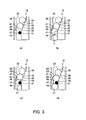
Fig. 3 is a plan view describing coin dispensing operations of the same coin dispenser as above in the order of (a) to (d). -
Fig. 4 is a sectional view describing operations for dispensing the last coin of the same coin dispenser as above in the order of (a) to (d). -
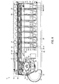
Fig. 5 is a sectional view of the same coin dispenser. -
Fig. 6 is a plan view of a coin handling machine to which the same coin dispenser as above is applied. -
Fig. 7 is a block diagram showing a control configuration for controlling the same coin dispenser as above. -
- 19
- Coin dispenser
- 31
- Coin storing unit
- 33
- Dispensing belt
- 47
- Second passage detection
- 51
- Coin stopper
- 52
- Solenoid as electromagnetic device
- 53
- Plunger
- 54
- Solenoid main body as electromagnetic device main body
- 61
- Control unit
- 62
- Number-of-stored-coins memory unit
- Hereinafter, an embodiment of the present invention will be described with reference to the drawings.
-
Fig. 6 is a plan view of a coin handling machine to which a coin dispenser is applied. - This coin handling machine is a coin depositing and dispensing
machine 11 capable of depositing and dispensing coins by communication with a POS register at, for example, a cashier station of a shop. - This coin depositing and dispensing
machine 11 has amachine body 12 formed to be narrow and long in the front-rear direction, and an input port not shown for inputting coins (shown by the reference symbol C in the drawing) to be deposited is formed at an upper face front portion of themachine body 12, and at the front face of themachine body 12, anoutlet 13 for dispensing coins to be dispensed is formed and a dispensingtray 14 that receives coins dispensed from theoutlet 13 is disposed. - Inside the
machine body 12, afeeding unit 15 that feeds coins input from the input port one by one, adeposit transport unit 16 that transports coins fed from thefeeding unit 15 from the front side to the rear side along the left side face inside themachine body 12, arecognition unit 17 that recognizes coins being transported by thedeposit transport unit 16, a plurality ofdiverting units 18 that divert coins being transported by thedeposit transport unit 16 by denomination according to the results of recognition by therecognition unit 17, denomination-specific coin dispensers 19 that are disposed in order from the front side to the rear side of themachine body 12 and store coins diverted by thediverting units 18 by denomination and dispense the stored coins one by one rightward inside themachine body 12, and a dispensingtransport unit 20 that is disposed along the right side inside themachine body 12 and transports coins dispensed from thecoin dispensers 19 to theoutlet 13. - The
feeding unit 15 includes arotary disk 21 that rotates at a position inclined at a predetermined angle with respect to the horizontal direction, and ahopper 22 that receives coins input from the input port, with the surface side of therotary disk 21 facing the inside of thehopper 22. On the surface of therotary disk 21, a plurality of pick-upmembers 23 are disposed at predetermined pitches along the circumferential direction. When therotary disk 21 rotates, the pick-upmembers 23 pick up coins inside thehopper 22 one by one to a region above therotary disk 21 and feed the picked-up coins to thedeposit transport unit 16. - The
deposit transport unit 16 includes adeposit transport passage 24 formed from the front side to the rear side along the left side upper portion inside themachine body 12. Adeposit transport belt 25 that transports coins along thedeposit transport passage 24 is disposed. In thedeposit transport passage 24, in order from the upstream side in the transporting direction, therecognition unit 17 and the plurality ofdiverting units 18 are disposed. - The
recognition unit 17 recognizes whether coins are acceptable into themachine body 12 and denominations, etc., of acceptable coins by detecting the materials and diameters of the coins. - Among the diverting
units 18, the divertingunit 18 positioned at the extremely upstream side in the transporting direction diverts rejected coins that are unacceptable into themachine body 12. A plurality of divertingunits 18 on the downstream side in the transporting direction relative to this rejectedcoin diverting unit 18 divert coins acceptable into themachine body 12 by denomination and store the coins in the denomination-specific coin dispensers 19. The rejected coins diverted by the rejectedcoin diverting unit 18 are returned to a return port not shown provided on the front face of themachine body 12. - The dispensing
transport unit 20 includes, as shown inFig. 5 andFig. 6 , an endlessdispensing transport belt 26 disposed horizontally along the front-rear direction of themachine body 12 on the lateral portions in the coin dispensing direction of the plurality ofcoin dispensers 19. The upper surface of the dispensingtransport belt 26 is disposed at a position lower than the coin dispensing positions of thecoin dispensers 19, and coins dispensed from thecoin dispensers 19 are received on the upper surface of the dispensingtransport belt 26 and transported to theoutlet 13. The upper surface of the dispensingtransport belt 26 is surrounded by a passage wall not shown on thecoin dispenser 19 side, apassage wall 27 on the opposite side, and a passageupper wall 28. The distance between the upper surface of the dispensingtransport belt 26 and the passageupper wall 28 is set to be smaller than the diameter of a coin with the smallest diameter to be handled by the coin depositing and dispensingmachine 11 so as to prevent coins from standing upright. - Next, the
coin dispenser 19 will be described. - As shown in
Fig. 5 andFig. 6 , thecoin dispenser 19 includes acoin storing unit 31 that stores coins in an unarrayed state. At the upper portion of thiscoin storing unit 31, a receivingport 32 for receiving coins diverted by the divertingunit 18 from thedeposit transport passage 24 is formed. At the bottom portion of thecoin storing unit 31, a dispensingbelt 33 that supports coins stored in an unarrayed state is disposed. This dispensingbelt 33 is an endless flat belt that is suspended so as to rise and incline toward the coin dispensing side by a plurality ofrollers including rollers belt 33 is formed as a dispensingport 36 for dispensing coins one by one. - Above the dispensing
belt 33 between thecoin storing unit 31 and the dispensingport 36 side, areverse roller 37 is opposed to the upper surface of the dispensingbelt 33 while forming a distance that allows only one coin to pass through. Thisreverse roller 37 rotates in a direction opposite to the dispensing direction in which the dispensingbelt 33 rotates, and arrays coins to be dispensed in the dispensing direction by rotation of the dispensingbelt 33 in one layer and causes the coins to pass through. - As shown in
Fig. 3 andFig. 6 , in both side regions of the dispensingbelt 33,guide members port 36 in one row, are disposed. Theseguide members guide surfaces belt 33, and the opposing distance of these guide surfaces 40 and 41 is formed to be larger than the diameter of one coin to be handled and smaller than the diameter of two coins. - On the end portion sides in the dispensing direction of the
guide members port 36, one-side-aligningportions belt 33 as they become closer to the coin dispensing side are formed. The one-side-aligningportion 42 of oneguide member 38 is disposed to advance to a position on the dispensingbelt 33, and the one-side-aligningportion 43 of theother guide member 39 is disposed outward away from the other side of the dispensingbelt 33, and agap 44 is formed between the one-side-aligningportion 43 of theother guide member 39 and the other side of the dispensingbelt 33. - A light emitter and a light receiver of each one of the two sensors, i.e. the first
passage detection sensor 46 and the secondpassage detection sensor 47, are opposed to each other so thatoptical axes 45 pass through thegap 44 between the one-side-aligningportion 43 of theother guide member 39 and the other side of the dispensingbelt 33. Thesepassage detection sensors optical axes 45 between light emitter and the light receiver of each respectivepassage detection sensor - On the one-
side aligning portion 42 side of oneguide member 38, acoin stopper 51 that stops a coin next in line to the last coin of a predetermined number of coins is disposed. Thiscoin stopper 51 consists of aplunger 53 of asolenoid 52 as an electromagnetic device disposed above the dispensingbelt 33 as shown inFig. 1, Fig. 2 , andFig. 5 , and can advance to and retract from a position on the dispensingbelt 33 from a position above the dispensingbelt 33 by driving of thesolenoid 52. - The
solenoid 52 includes a solenoidmain body 54 as an electromagnetic device main body and aplunger 53 that advances to and retracts from the solenoidmain body 54. The solenoidmain body 54 includes acoil 55 that generates a magnetic force for adsorbing and moving theplunger 53 by excitation, and a spring not shown that causes theplunger 53 to protrude by canceling excitation, etc. A portion on the base end side of theplunger 53 disposed inside the solenoidmain body 54 is formed as amagnetic body portion 56 made of a magnetic material, and the tip end portion that comes into contact with a coin of theplunger 53 is formed as anonmagnetic body portion 57 made of a nonmagnetic material, for example, plastic or stainless steel. The tip end portion of theplunger 53 is formed to be spherical. - The
solenoid 52 allows a coin to pass in the dispensing direction by pulling up theplunger 53 by excitation and retracting thecoin stopper 51 upward, and can block passage of a coin next in line to the last coin of a predetermined number of coins in the dispensing direction by advancing thecoin stopper 51 to the position on the dispensingbelt 33 by making theplunger 53 protrude downward by the spring of thesolenoid 52 by canceling excitation. - A central portion that comes into contact with a coin surface of the
coin stopper 51 is positioned between the firstpassage detection sensor 46 and the secondpassage detection sensor 47 in the dispensing direction. Specifically, the secondpassage detection sensor 47 is disposed in the region downstream in the dispensing direction relative to the position of thecoin stopper 51. -
Fig. 7 is a block diagram showing a control configuration for controlling thecoin dispenser 19. - The
control unit 61 that controls thecoin dispenser 19 inputs a signal frompassage detection sensors coins memory unit 62, etc., that stores in memory the number of coins stored in thecoin storing unit 31 and controls amotor 63 that drives and rotates the dispensingbelt 33 and thereverse roller 37 and thesolenoid 52, etc. - The number-of-stored-
coins memory unit 62 stores in memory a number of stored coins by summing the coins based on recognition by therecognition unit 17 when depositing coins, and stores in memory a number of stored coins by subtracting coins dispensed from thecoin dispenser 19 detected by the secondpassage detection sensor 47 when dispensing coins. - The
control unit 61 has the following functions. - A function to compare the number of coins stored in the number-of-stored-
coins memory unit 62 and the number of coins counted by the secondpassage detection sensor 47. - A normal stop control function to advance the
coin stopper 51 to the position on the surface of the last coin of a predetermined number of coins by canceling excitation of thesolenoid 52 when the last coin of the predetermined number of coins passes through the firstpassage detection sensor 46 in a case where the last coin of the predetermined number of coins to be dispensed is not the last coin of the stored coins. - A first retry function to confirm whether the last coin of a predetermined number of coins is dispensed and the second
passage detection sensor 47 enters a light-transmitting state by temporarily retracting thecoin stopper 51 by turning thesolenoid 52 on and off in a short time when the last coin of the predetermined number of coins is caught by thecoin stopper 51 and is not dispensed and the secondpassage detection sensor 47 continuously detects the coin for a predetermined time or more in normal stop control. Alternatively, a second retry control function to confirm whether the last coin of a predetermined number of coins is dispensed and the secondpassage detection sensor 47 enters a light-transmitting state by repeatedly rotating the dispensingbelt 33 forward and reversely a predetermined number of times when the last coin of the predetermined number of coins is not dispensed for some reason such as catching by thecoin stopper 51 and the secondpassage detection sensor 47 continuously detects the coin for a predetermined time or more. - A function for final stop control to advance the
coin stopper 51 to the position on the dispensingbelt 33 by canceling excitation of thesolenoid 52 after the last coin passes through the secondpassage detection sensor 47 when the last coin of a predetermined number of coins to be dispensed is the last coin of stored coins. - Next, operations of the coin depositing and dispensing
machine 11 will be described. - First, deposit processing of the coin depositing and dispensing
machine 11 will be described. - The coins to be deposited input from the input port are received in the
feeding unit 15, and fed one by one from thisfeeding unit 15 to thedeposit transport unit 16, and transported one by one inside thedeposit transport unit 16. - Coins being transported inside the
deposit transport unit 16 are recognized by therecognition unit 17. As a result of recognition, coins recognized as normal coins are diverted by denomination by the denomination-specific divertingunits 18 and stored in thecoin storing units 31 of the denomination-specific coin dispensers 19. On the other hand, as a result of recognition, rejected coins such as unidentified coins are excluded and returned by the divertingunit 18 on the extremely upstream side of thedeposit transport unit 16. - Next, dispensing processing of the coin depositing and dispensing
machine 11 will be described. - For example, in response to a signal of a dispensing command from a POS register, the dispensing
belts 33 of thecoin dispensers 19 rotate and thereverse rollers 37 reverse, and coins in an unarrayed state on the dispensingbelts 33 inside thecoin storing units 31 are arrayed in one layer and one row and moved in the dispensing direction. - In the
coin dispenser 19 for a denomination to be dispensed, thecoin stopper 51 is retracted, and coins are dispensed from the dispensingport 36 to the dispensingtransport unit 20 by the dispensingbelt 33. According to passage of the coins to be dispensed through the secondpassage detection sensor 47, the number of coins dispensed is counted. - In the
coin dispenser 19 for a denomination not to be dispensed and thecoin dispenser 19 for a denomination to be dispensed from which dispensing of the required number of coins has been finished, thecoin stopper 51 is advanced to the position on the dispensingbelt 33 to restrict dispensing of coins. - Then, coins are dispensed from the
outlet 13 into the dispensingtray 14 by the dispensingtransport unit 20. At this time, concurrently with start of a dispensing operation from thecoin dispensers 19, transportation to theoutlet 13 by the dispensingtransport unit 20 is started, and coins to be dispensed from thecoin dispensers 19 are successively dispensed to theoutlet 13, or after all coins to be dispensed from thecoin dispensers 19 are stored on the dispensingtransport belt 26 of the dispensingtransport unit 20, all the coins are dispensed at one time to theoutlet 13. - When all the coins are dispensed at one time to the
outlet 13, if the number of coins to be dispensed from onedispenser 19 is large, a plurality of coins may become stagnant on the dispensingtransport belt 26 near the dispensingport 36 of thecoin dispenser 19, and dispensing of the following coins to be dispensed from thecoin dispenser 19 may fail. Therefore, when the number of coins to be dispensed from thecoin dispenser 19 is large, the motor for driving the dispensingtransport belt 26 is repeatedly rotated forward and reversely to move the dispensingtransport belt 26 little by little in the belt longitudinal direction, and accordingly, the coins dispensed onto the dispensingtransport belt 26 are dispersed in the belt longitudinal direction, and a predetermined number of coins can be reliably dispensed from thecoin dispenser 19. - Next, a coin dispensing operation from the
coin dispenser 19 will be described. - First, as shown in
Fig. 3 , a case where the last coin of a predetermined number of coins to be dispensed is not the last coin of stored coins when dispensing the predetermined number of coins from thecoin dispenser 19 will be described. - As shown in
Fig. 3(a) , in a standby state, thesolenoid 52 is turned off, and by bias of the spring of thesolenoid 52, thecoin stopper 51 advances to the position on the dispensingbelt 33 and blocks passage of coins. InFigs. 3 , when thesolenoid 52 is off, thecoin stopper 51 is indicated in black, and when thesolenoid 52 is on, thecoin stopper 51 is indicated in white. - As shown in
Fig. 3(b) , when an operation for dispensing a predetermined number of coins from thecoin dispenser 19 is started, thesolenoid 52 is turned on and retracts thecoin stopper 51 upward. Coins that move in the dispensing direction by the dispensingbelt 33 rotating are dispensed by passing through the position below thecoin stopper 51. - A coin to be dispensed is detected by the
passage detection sensors passage detection sensor 47 and the secondpassage detection sensor 47 enters a light-transmitting state, the number of coins dispensed is counted. The number of coins stored in the number-of-stored-coins memory unit 62 and the number of coins counted by the secondpassage detection sensor 47 are compared. Here, the last coin of a predetermined number of coins to be dispensed is not the last coin of stored coins. - As shown in
Fig. 3(c) , when the last coin C1 of a predetermined number of coins passes through the firstpassage detection sensor 46 and the firstpassage detection sensor 46 enters a light-transmitting state, thesolenoid 52 is turned off, and by bias of the spring of thesolenoid 52, thecoin stopper 51 advances downward, and the tip end portion of thecoin stopper 51 comes into contact with the coin surface of the last coin C1 of the predetermined number of coins. - Even after the
coin stopper 51 comes into contact with the last coin C1 of the predetermined number of coins, the frictional force between the dispensingbelt 33 and the last coin C1 of the predetermined number of coins is larger than the frictional force between thecoin stopper 51 and the last coin C1 of the predetermined number of coins, and a pushing force is applied to the coin of the last coin C1 of the predetermined number of coins by the following coins, so that the last coin C1 of the predetermined number of coins is moved in the dispensing direction by the dispensingbelt 33. - As shown in
Fig. 3(d) , the last coin C1 of the predetermined number of coins passes through the position below thecoin stopper 51 and departs from thecoin stopper 51, thecoin stopper 51 falls into the gap between the last coin C1 of the predetermined number of coins and the coin C2 next in line and advances to the position on the dispensingbelt 33. - The last coin C1 of the predetermined number of coins is dispensed from the dispensing
port 36, the coin C2 next in line to the last coin of the predetermined number of coins comes into contact with thecoin stopper 51 advanced to the position on the dispensingbelt 33, and even if the dispensingbelt 33 continuously rotates, the coin C2 next in line to the last coin of the predetermined number of coins is restricted from being dispensed. - Thus, when the last coin C1 of a predetermined number of coins to be dispensed is not the last coin of the stored coins, at a timing at which the last coin C1 of the predetermined number of coins passes through the first
passage detection sensor 46, thecoin stopper 51 is advanced to a position on the coin surface of the last coin C1 of the predetermined number of coins, so that thecoin stopper 51 can be reliably advanced to the gap between the last coin C1 of the predetermined number of coins and the coin C2 next in line, and the coin C2 next in line to the last coin C1 of the predetermined number of coins can be reliable stopped. - Further, as shown in
Fig. 3(c) , thesolenoid 52 is turned off, and thecoin stopper 51 is advanced downward by bias of the spring of thesolenoid 52, and in a state where the tip end portion of thecoin stopper 51 is in contact with the coin surface of the last coin C1 of a predetermined number of coins, if a dispensing failure in which the edge portion of the last coin C1 of the predetermined number of coins is caught by thecoin stopper 51 and the coin is not dispensed occurs, this dispensing failure is detected by continuous detection of the coin for a predetermined time or more by the secondpassage detection sensor 47. When this dispensing failure is detected, a first retry control is performed to confirm whether the last coin C1 of the predetermined number of coins is dispensed and the secondpassage detection sensor 47 enters a light-transmitting state by turning thesolenoid 52 on and off in a short time to temporarily retract thecoin stopper 51. - In the first retry control, as shown in
Fig. 1 , in a state where the tip end portion of thecoin stopper 51 is in contact with the coin surface of the last coin C1 of a predetermined number of coins, thesolenoid 52 is turned on. In this case, themagnetic body portion 56 of theplunger 53 is magnetized, however, the member in contact with the coin surface of the coin C1 is thenonmagnetic body portion 57 at the tip end portion of theplunger 53, so that the even if the coin C1 is magnetic, the coin C1 is not adsorbed to thecoin stopper 51. Therefore, as shown inFig. 2 , when thecoin stopper 51 is retracted upward, the coin C1 is moved in the dispensing direction by the dispensingbelt 33 and the dispensing failure is eliminated. - Thus, the contact portion of the
coin stopper 51, which comes into contact with the coin, is made of a nonmagnetic material, so that even a magnetic coin can also be reliably dispensed. Therefore, even if thecoin stopper 51 is theplunger 53 of thesolenoid 52, thecoin stopper 51 does not magnetically adsorb a coin, and coins can be reliably dispensed. - By turning the
solenoid 52 on and off in a short time, thecoin stopper 51 is advanced to the edge portion of the coin surface of the last coin C1 of a predetermined number of coins or the gap between the last coin C1 of the predetermined number of coins and the coin C2 next in line, and the coin C2 next in line to the last coin C1 of the predetermined number of coins can be reliably stopped. - If the timing to advance the
coin stopper 51 delays and the coin C2 next in line to the last coin C1 of a predetermined number of coins is dispensed, it is processed as an excessive dispensing error. - The retry control is not limited to this first retry control, and a second retry control may be performed in which it is confirmed whether the last coin of a predetermined number of coins is dispensed and the second
passage detection sensor 47 enters a light-transmitting state by repeatedly rotating the dispensingbelt 33 forward and reversely a predetermined number of times. Alternatively, it is also possible that by combining the first retry control and the second retry control, a coin of a predetermined number is reliably dispensed while restraining the coin next in line to the last coin of the predetermined number of coins from being dispensed. - Subsequently, as shown in
Fig. 4 , a dispensing operation in a case where the last coin of a predetermined number of coins to be dispensed is the last coin of stored coins when dispensing the predetermined number of coins from thecoin dispenser 19 will be shown. - As shown in
Fig. 4(a) , in a standby state, thesolenoid 52 is turned off, and thecoin stopper 51 is advanced to the position on the dispensingbelt 33 by bias of the spring of thesolenoid 52 and blocks passage of coins. InFigs. 4 , when thesolenoid 52 is off, thecoin stopper 51 is indicated in black, and when thesolenoid 52 is on, thecoin stopper 51 is indicated in white. - As shown in
Fig. 4(b) , when an operation to dispense a predetermined number of coins from thecoin dispenser 19 is started, thesolenoid 52 is turned on and retracts thecoin stopper 51 upward. The coins moved in the dispensing direction by the dispensingbelt 33 rotating pass through the position below thecoin stopper 51 and are dispensed. - When a coin to be dispensed is detected by the
passage detection sensors passage detection sensor 47, and the secondpassage detection sensor 47 enters a light-transmitting state, the number of coins dispensed is counted. The number of coins stored in the number-of-stored-coins memory unit 62 and the number of coins counted by the secondpassage detection sensor 47 are compared. Here, the last coin of a predetermined number of coins to be dispensed is the last coin of stored coins. - As shown in
Fig. 4(c) , even after the last coin C1 that is the last coin of a predetermined number of coins and also the last coin of stored coins passes through the firstpassage detection sensor 46 and the firstpassage detection sensor 46 enters a light-transmitting state, the on state of thesolenoid 52 is maintained and thecoin stopper 51 is left retracted. - As shown in
Fig. 4(d) , when the last coin C1 passes through the secondpassage detection sensor 47 and the secondpassage detection sensor 47 enters a light-transmitting state, thesolenoid 52 is turned off, thecoin stopper 51 is advanced downward by bias of the spring of thesolenoid 52, and thecoin stopper 51 is advanced to the position on the dispensingbelt 33. - At this time, the last coin C1 has passed through the position below the
coin stopper 51, and is dispensed without contact with thecoin stopper 51. - Thus, in the case where the last coin C1 of a predetermined number of coins to be dispensed is the last coin of stored coins, the timing to advance the
coin stopper 51 is changed so that thecoin stopper 51 advances to the position on the dispensingbelt 33 after the last coin C1 passes through the secondpassage detection sensor 47, and accordingly, the last coin C1 can be reliably dispensed. - Even when the last coin C1 of a predetermined number of coins to be dispensed is the last coin of stored coins, it is also possible that the
coin stopper 51 is controlled by normal stop control shown inFig. 3 , and at the time of retry in the case where a dispensing failure occurs, thecoin stopper 51 is controlled by the final stop control shown inFig. 4 . - The
coin stopper 51 is not limited to theplunger 53 of thesolenoid 52, and may be disposed so as to advance to and retract from the position on the dispensingbelt 33, and configured so as to transmit a driving force of a solenoid, etc., disposed at a different location via a link, etc. In this case, the entirety of thecoin stopper 51 may be made of a nonmagnetic material, thecoin stopper 51 does not magnetically adsorb a coin, and coins can be reliably dispensed. - The present invention is applicable to a coin handling machine using a coin dispenser, such as a coin depositing and dispensing machine, a coin dispensing machine, and a coin wrapping machine.
Claims (4)
- A coin dispenser comprising:a coin storing unit that stores coins in an unarrayed state;a dispensing belt that constitutes a part of the bottom surface of the coin storing unit and dispenses coins in a single-layered state from the inside of the coin storing unit; anda coin stopper that is made of a nonmagnetic material at least at a portion to come into contact with a coin, advances to and retracts from a position on the dispensing belt, allows a coin to pass in a dispensing direction by retracting from the dispensing belt, and after advancing to a position on the surface of a coin to be dispensed, advances to the position on the dispensing belt before the coin next in line and blocks passage of the coin next in line.
- The coin dispenser according to Claim 1, comprising:an electromagnetic device having a plunger and an electromagnetic device main body that advances and retracts the plunger by electromagnetic action, whereinthe coin stopper is the plunger.
- The coin dispenser according to Claim 1, wherein
the entirety of the coin stopper is made of a nonmagnetic material. - The coin dispenser according to Claim 1, comprising:a number-of-stored-coins memory unit that stores in memory the number of coins stored in the coin storing unit;a passage detection sensor that is provided in a region downstream in the dispensing direction relative to a position of the coin stopper, and detects passage of each coin to be dispensed and counts the coins; anda control unit that performs control so that the coin stopper advances to the position on the dispensing belt after the last coin passes through the passage detection sensor when the last coin to be dispensed is the last coin of the stored coins based on a comparison between the number of coins stored in the number-of-stored-coins memory unit and the number of coins counted by the passage detection sensor.
Applications Claiming Priority (1)
| Application Number | Priority Date | Filing Date | Title |
|---|---|---|---|
| PCT/JP2008/073573 WO2010073334A1 (en) | 2008-12-25 | 2008-12-25 | Coin dispensing device |
Publications (2)
| Publication Number | Publication Date |
|---|---|
| EP2383704A1 true EP2383704A1 (en) | 2011-11-02 |
| EP2383704A4 EP2383704A4 (en) | 2012-08-01 |
Family
ID=42287003
Family Applications (1)
| Application Number | Title | Priority Date | Filing Date |
|---|---|---|---|
| EP08879130A Withdrawn EP2383704A4 (en) | 2008-12-25 | 2008-12-25 | Coin dispenser |
Country Status (3)
| Country | Link |
|---|---|
| EP (1) | EP2383704A4 (en) |
| JP (1) | JPWO2010073334A1 (en) |
| WO (1) | WO2010073334A1 (en) |
Family Cites Families (7)
| Publication number | Priority date | Publication date | Assignee | Title |
|---|---|---|---|---|
| JPS6347946Y2 (en) * | 1980-06-24 | 1988-12-09 | ||
| GB9217450D0 (en) * | 1992-08-17 | 1992-09-30 | Case Icc Limited | Coin transporting apparatus and coin validation apparatus employing same |
| JP3267697B2 (en) * | 1992-10-22 | 2002-03-18 | グローリー工業株式会社 | Coin processing machine |
| JP4119141B2 (en) | 2002-03-14 | 2008-07-16 | 東芝テック株式会社 | Coin dispenser |
| JP4997374B2 (en) * | 2005-10-19 | 2012-08-08 | 旭精工株式会社 | Coin denomination sorter |
| JP2007257545A (en) * | 2006-03-24 | 2007-10-04 | Toshiba Tec Corp | Coin dispenser |
| EP2116979A4 (en) * | 2007-02-01 | 2010-08-04 | Glory Kogyo Kk | Coin receiving/paying machine |
-
2008
- 2008-12-25 WO PCT/JP2008/073573 patent/WO2010073334A1/en not_active Ceased
- 2008-12-25 EP EP08879130A patent/EP2383704A4/en not_active Withdrawn
- 2008-12-25 JP JP2010543673A patent/JPWO2010073334A1/en active Pending
Also Published As
| Publication number | Publication date |
|---|---|
| WO2010073334A1 (en) | 2010-07-01 |
| JPWO2010073334A1 (en) | 2012-05-31 |
| EP2383704A4 (en) | 2012-08-01 |
Similar Documents
| Publication | Publication Date | Title |
|---|---|---|
| US9189905B2 (en) | Coin handling machine | |
| US8371911B2 (en) | Coin transporting device and coin handling machine | |
| EP2091026B1 (en) | Coin receiving and discharging device | |
| US8961276B2 (en) | Coin feeding device | |
| JPWO2008093420A1 (en) | Coin deposit and withdrawal machine | |
| US8961275B2 (en) | Coin depositing and dispensing machine | |
| US11989994B2 (en) | Bundle module of medium deposit device | |
| JP6197615B2 (en) | Coin storage, coin storage control method, and coin processing apparatus | |
| WO2008072545A1 (en) | Coin handling device | |
| JP6019579B2 (en) | Coin processing equipment | |
| KR101609458B1 (en) | Coin handling apparatus and financial device | |
| JP6540244B2 (en) | Coin sorting apparatus and coin handling apparatus | |
| JP2509366Y2 (en) | Circular coin depositing and dispensing machine | |
| JP4119141B2 (en) | Coin dispenser | |
| JP5203816B2 (en) | Coin dispenser | |
| JPH10241005A (en) | Automatic change payment device | |
| JP4897828B2 (en) | Coin storage and feeding device | |
| WO2010073334A1 (en) | Coin dispensing device | |
| JP2004256251A (en) | Paper money storage device and paper money receiving and paying machine | |
| KR101447823B1 (en) | Coin handling apparatus and financial device | |
| JP3552215B2 (en) | Coin deposit and withdrawal device |
Legal Events
| Date | Code | Title | Description |
|---|---|---|---|
| PUAI | Public reference made under article 153(3) epc to a published international application that has entered the european phase |
Free format text: ORIGINAL CODE: 0009012 |
|
| 17P | Request for examination filed |
Effective date: 20110725 |
|
| AK | Designated contracting states |
Kind code of ref document: A1 Designated state(s): AT BE BG CH CY CZ DE DK EE ES FI FR GB GR HR HU IE IS IT LI LT LU LV MC MT NL NO PL PT RO SE SI SK TR |
|
| DAX | Request for extension of the european patent (deleted) | ||
| A4 | Supplementary search report drawn up and despatched |
Effective date: 20120703 |
|
| RIC1 | Information provided on ipc code assigned before grant |
Ipc: G07D 3/14 20060101AFI20120627BHEP Ipc: G07D 1/02 20060101ALI20120627BHEP Ipc: G07D 3/16 20060101ALI20120627BHEP |
|
| 17Q | First examination report despatched |
Effective date: 20160712 |
|
| STAA | Information on the status of an ep patent application or granted ep patent |
Free format text: STATUS: THE APPLICATION IS DEEMED TO BE WITHDRAWN |
|
| 18D | Application deemed to be withdrawn |
Effective date: 20161123 |