EP2383634A2 - Input device - Google Patents
Input device Download PDFInfo
- Publication number
- EP2383634A2 EP2383634A2 EP10166876A EP10166876A EP2383634A2 EP 2383634 A2 EP2383634 A2 EP 2383634A2 EP 10166876 A EP10166876 A EP 10166876A EP 10166876 A EP10166876 A EP 10166876A EP 2383634 A2 EP2383634 A2 EP 2383634A2
- Authority
- EP
- European Patent Office
- Prior art keywords
- controller
- sensor
- data
- gyro
- mode
- Prior art date
- Legal status (The legal status is an assumption and is not a legal conclusion. Google has not performed a legal analysis and makes no representation as to the accuracy of the status listed.)
- Granted
Links
Images











Classifications
-
- G—PHYSICS
- G06—COMPUTING OR CALCULATING; COUNTING
- G06F—ELECTRIC DIGITAL DATA PROCESSING
- G06F3/00—Input arrangements for transferring data to be processed into a form capable of being handled by the computer; Output arrangements for transferring data from processing unit to output unit, e.g. interface arrangements
- G06F3/01—Input arrangements or combined input and output arrangements for interaction between user and computer
- G06F3/03—Arrangements for converting the position or the displacement of a member into a coded form
- G06F3/033—Pointing devices displaced or positioned by the user, e.g. mice, trackballs, pens or joysticks; Accessories therefor
- G06F3/0346—Pointing devices displaced or positioned by the user, e.g. mice, trackballs, pens or joysticks; Accessories therefor with detection of the device orientation or free movement in a three-dimensional [3D] space, e.g. 3D mice, 6-DOF [six degrees of freedom] pointers using gyroscopes, accelerometers or tilt-sensors
-
- A—HUMAN NECESSITIES
- A63—SPORTS; GAMES; AMUSEMENTS
- A63F—CARD, BOARD, OR ROULETTE GAMES; INDOOR GAMES USING SMALL MOVING PLAYING BODIES; VIDEO GAMES; GAMES NOT OTHERWISE PROVIDED FOR
- A63F13/00—Video games, i.e. games using an electronically generated display having two or more dimensions
- A63F13/20—Input arrangements for video game devices
- A63F13/23—Input arrangements for video game devices for interfacing with the game device, e.g. specific interfaces between game controller and console
-
- A—HUMAN NECESSITIES
- A63—SPORTS; GAMES; AMUSEMENTS
- A63F—CARD, BOARD, OR ROULETTE GAMES; INDOOR GAMES USING SMALL MOVING PLAYING BODIES; VIDEO GAMES; GAMES NOT OTHERWISE PROVIDED FOR
- A63F13/00—Video games, i.e. games using an electronically generated display having two or more dimensions
- A63F13/20—Input arrangements for video game devices
- A63F13/21—Input arrangements for video game devices characterised by their sensors, purposes or types
- A63F13/211—Input arrangements for video game devices characterised by their sensors, purposes or types using inertial sensors, e.g. accelerometers or gyroscopes
-
- A—HUMAN NECESSITIES
- A63—SPORTS; GAMES; AMUSEMENTS
- A63F—CARD, BOARD, OR ROULETTE GAMES; INDOOR GAMES USING SMALL MOVING PLAYING BODIES; VIDEO GAMES; GAMES NOT OTHERWISE PROVIDED FOR
- A63F13/00—Video games, i.e. games using an electronically generated display having two or more dimensions
- A63F13/20—Input arrangements for video game devices
- A63F13/23—Input arrangements for video game devices for interfacing with the game device, e.g. specific interfaces between game controller and console
- A63F13/235—Input arrangements for video game devices for interfacing with the game device, e.g. specific interfaces between game controller and console using a wireless connection, e.g. infrared or piconet
-
- A—HUMAN NECESSITIES
- A63—SPORTS; GAMES; AMUSEMENTS
- A63F—CARD, BOARD, OR ROULETTE GAMES; INDOOR GAMES USING SMALL MOVING PLAYING BODIES; VIDEO GAMES; GAMES NOT OTHERWISE PROVIDED FOR
- A63F13/00—Video games, i.e. games using an electronically generated display having two or more dimensions
- A63F13/20—Input arrangements for video game devices
- A63F13/24—Constructional details thereof, e.g. game controllers with detachable joystick handles
-
- G—PHYSICS
- G06—COMPUTING OR CALCULATING; COUNTING
- G06F—ELECTRIC DIGITAL DATA PROCESSING
- G06F3/00—Input arrangements for transferring data to be processed into a form capable of being handled by the computer; Output arrangements for transferring data from processing unit to output unit, e.g. interface arrangements
- G06F3/01—Input arrangements or combined input and output arrangements for interaction between user and computer
- G06F3/03—Arrangements for converting the position or the displacement of a member into a coded form
- G06F3/033—Pointing devices displaced or positioned by the user, e.g. mice, trackballs, pens or joysticks; Accessories therefor
- G06F3/038—Control and interface arrangements therefor, e.g. drivers or device-embedded control circuitry
-
- A—HUMAN NECESSITIES
- A63—SPORTS; GAMES; AMUSEMENTS
- A63F—CARD, BOARD, OR ROULETTE GAMES; INDOOR GAMES USING SMALL MOVING PLAYING BODIES; VIDEO GAMES; GAMES NOT OTHERWISE PROVIDED FOR
- A63F13/00—Video games, i.e. games using an electronically generated display having two or more dimensions
- A63F13/20—Input arrangements for video game devices
- A63F13/21—Input arrangements for video game devices characterised by their sensors, purposes or types
- A63F13/213—Input arrangements for video game devices characterised by their sensors, purposes or types comprising photodetecting means, e.g. cameras, photodiodes or infrared cells
-
- A—HUMAN NECESSITIES
- A63—SPORTS; GAMES; AMUSEMENTS
- A63F—CARD, BOARD, OR ROULETTE GAMES; INDOOR GAMES USING SMALL MOVING PLAYING BODIES; VIDEO GAMES; GAMES NOT OTHERWISE PROVIDED FOR
- A63F2300/00—Features of games using an electronically generated display having two or more dimensions, e.g. on a television screen, showing representations related to the game
- A63F2300/10—Features of games using an electronically generated display having two or more dimensions, e.g. on a television screen, showing representations related to the game characterized by input arrangements for converting player-generated signals into game device control signals
- A63F2300/1025—Features of games using an electronically generated display having two or more dimensions, e.g. on a television screen, showing representations related to the game characterized by input arrangements for converting player-generated signals into game device control signals details of the interface with the game device, e.g. USB version detection
-
- A—HUMAN NECESSITIES
- A63—SPORTS; GAMES; AMUSEMENTS
- A63F—CARD, BOARD, OR ROULETTE GAMES; INDOOR GAMES USING SMALL MOVING PLAYING BODIES; VIDEO GAMES; GAMES NOT OTHERWISE PROVIDED FOR
- A63F2300/00—Features of games using an electronically generated display having two or more dimensions, e.g. on a television screen, showing representations related to the game
- A63F2300/10—Features of games using an electronically generated display having two or more dimensions, e.g. on a television screen, showing representations related to the game characterized by input arrangements for converting player-generated signals into game device control signals
- A63F2300/1043—Features of games using an electronically generated display having two or more dimensions, e.g. on a television screen, showing representations related to the game characterized by input arrangements for converting player-generated signals into game device control signals being characterized by constructional details
-
- A—HUMAN NECESSITIES
- A63—SPORTS; GAMES; AMUSEMENTS
- A63F—CARD, BOARD, OR ROULETTE GAMES; INDOOR GAMES USING SMALL MOVING PLAYING BODIES; VIDEO GAMES; GAMES NOT OTHERWISE PROVIDED FOR
- A63F2300/00—Features of games using an electronically generated display having two or more dimensions, e.g. on a television screen, showing representations related to the game
- A63F2300/10—Features of games using an electronically generated display having two or more dimensions, e.g. on a television screen, showing representations related to the game characterized by input arrangements for converting player-generated signals into game device control signals
- A63F2300/105—Features of games using an electronically generated display having two or more dimensions, e.g. on a television screen, showing representations related to the game characterized by input arrangements for converting player-generated signals into game device control signals using inertial sensors, e.g. accelerometers, gyroscopes
Definitions
- the present invention relates to an input device. More specifically, the present invention relates to an input device for transmitting input data from at least one input portion to an information processing apparatus.
- an input device of such a kind is disclosed in Japanese Patent No. 4255510 (Patent Document 1).
- an operating device has an imaged information arithmetic section and an acceleration sensor, etc. as an input portion, and transmits position coordinate data from the imaged information arithmetic section, acceleration data from the acceleration sensor, etc. as input data to an information processing apparatus (game apparatus).
- the operating device is connected with an expansion operating device (gyro sensor unit) including a gyro sensor as another input potion via an expansion connector (common bus).
- the operating device is used so as to be integrated with the expansion operating device, and alternately transmits position coordinate data from the imaged information arithmetic section, acceleration data from the acceleration sensor, etc. as first input data and angular velocity data from the gyro sensor as second input data to the information processing apparatus.
- the expansion connector can be connected with other expansion operating device (second controller).
- the related art is for connecting the expansion operating device to the expansion connector, and therefore, the size of the operating device may be increased.
- the expansion connector can be connected with other expansion operating devices in order to maintain compatibility, so that the shape of the connector is required to be the same. Furthermore, depending on the expansion operating device, it is preferable that the shape of the housing is the same. Accordingly, even if the operating device integrated with the sensor is newly provided, it is assumed that it is provided to be physically connectable with the expansion operating device of the Patent Document 1.
- the user may erroneously connect the expansion operating device to the operating device integrated with the sensor, and in such a case, the same sensors may be connected to a common bus.
- the same address is assigned to both of the sensors, and data contention may occur on the common bus.
- Another object of the present invention is to provide, when in place of an input device to be used so as to be connected with an external expansion device, an input device integrated with a device having a function equivalent to that of the external expansion device is newly provided, the new input device with compatibility maintained.
- a still another object of the present invention is to provide a malfunction, etc. from occurring even when an erroneous external expansion device is connected to the aforementioned input device integrated with the device.
- the present invention adopts the following configurations for the purpose of solving the aforementioned problems.
- a controller which controls an input portion and acquires data is connected to a predetermined bus.
- the bus is connected with a predetermined external expansion device via an expansion connector, or may be connected with other device in place of or in addition to the external expansion device.
- the connection of the bus from the expansion connector to the controller is switched on or off by a switcher.
- the data acquired from the sensor having a function equivalent to the external expansion device is transmitted to the controller via the bus by a sensor controller which is connected to the side of the controller and the side of the expansion connector of the bus without interposing the switcher, and controls the switcher on or off.
- the sensor controller switches the connection of the switcher off when an access to itself is made from the controller.
- the connection from the expansion connector to the controller is switched off, and therefore, even if the external expansion device is connected with the expansion connector, a problem, such as data contention, etc. may be prevented between the sensor and the external expansion device.
- the shape of the housings may be the same, so that compatibility with the external expansion device is maintained.
- a second invention is an input device according to the first invention, and the sensor controller transmits a signal for transmitting data from the external expansion device to the side of the expansion connector, and discards data transmitted on the basis of the signal from the expansion connector when an access from the controller to itself is made.
- a signal for transmitting data from the external expansion device is transmitted from the sensor controller to the side of the expansion connector, and data transmitted from the external expansion device through the expansion connector is discarded by the sensor controller.
- the external expansion device when an access is made, by transmitting a signal to the external expansion device, the external expansion device is caused to transmit data, and the transmitted data is discarded, and therefore, even if an access reaches the device, the device can be returned to the original state.
- a third invention is an input device according to the first or the second invention, and the sensor is a gyro sensor.
- angular velocity data acquired from the gyro sensor is transmitted to the controller via the bus.
- the angular velocity is equal irrespective of which part of the input device the gyro sensor is attached, and therefore, the position of the sensor is changed due to be integrated, the information processing can be performed similar to a case that the sensor is externally attached.
- a fourth invention is an input device according to any one of the first to third inventions, and as to an access from the controller, a content of an instruction is transmitted following information indicating an object to be accessed, and the sensor controller determines whether or not the object to be accessed from the controller is itself, and switches the connection of the switcher off before the instruction from the controller is transmitted to the expansion connector if the object to be accessed from the controller is itself.
- an access from the controller includes information indicating an object and a content of an instruction.
- the information indicating the object is first transmitted, and the content of the instruction is secondly transmitted.
- the sensor controller determines whether or not the object is itself on the basis of the information first transmitted, and if it is determined that the object is itself, the connection of the switcher can be switched off before the content of the instruction is transmitted.
- the fourth invention even if the external expansion device is connected to the expansion connector, an instruction from the controller does not reach the external expansion device, and therefore, it is possible to prevent a malfunction of the external expansion device due to the instruction from the controller from occurring.
- a fifth invention is an input device according to the fourth invention, and the sensor controller has a plurality of modes including at least a mode in which the sensor is used and a mode in which the sensor is not used, and makes a mode transition, activates the sensor, and transmits data from the sensor to the controller thereafter if the content of the instruction from the controller is a mode transition from the mode in which the sensor is not used to the mode in which the sensor is used.
- a mode transition from the controller to the sensor controller does not reach the external expansion device, and this makes it possible to make only the sensor controller make a mode transition and start to use the sensor.
- a sixth invention is an input device according to the fifth invention, and the sensor controller, if other device is connected via the expansion connector in the mode in which the sensor is used, acquires data from the other device, and alternately transmits the data from the other device and data acquired from the sensor to the controller.
- a seventh invention is an input device according to the fifth or the sixth invention, and the sensor controller further switches the connection of the switcher on when a mode transition to the mode in which the sensor is not used is instructed from the controller in the mode in which the sensor is used.
- the connection of the switcher in accordance with a mode transition from the mode in which the sensor is used to the mode in which the sensor is not used, the connection of the switcher is changed from off to on.
- a bypass from the expansion connector to the controller is made, and therefore, the data from the other device connected to the expansion connector can be transmitted to the controller without interposing the sensor controller.
- the seventh invention it is possible to reduce load on the sensor controller.
- An eighth invention is an input device according to the fourth invention, and the information indicating the object to be accessed and the content of the instruction when the object to be accessed from the controller is itself is the same signal as that for controlling the external expansion device.
- the controller can access the sensor controller by using the signal the same as that (access data) for controlling the external expansion device, and therefore, the controller is not required to be changed.
- a ninth invention is an input device transmitting input data from at least one input potion to an information processing apparatus, and in the input device comprising: a controller which is connected to a predetermined bus, controls the input portion, and acquires data; an expansion connector which connects various devices including a predetermined external expansion device to the bus; a switcher which switches on or off a connection of the bus from the expansion connector to the controller; a sensor which has a function being equivalent to that of the external expansion device; and a sensor controlling computer which transmits data acquired from the sensor to the controller via the bus, is connected to a side of the controller and a side of the expansion connector of the bus without interposing the switcher, and controls the switcher on or off, the sensor controlling program causes the sensor controlling computer to function as a means which switches the connection of the switcher off when an access to itself is made from the controller.
- an input device integrated with a device having a function equivalent to that of the external expansion device is newly provided, the new input device with compatibility maintained. Additionally, even if a conventional external expansion device is erroneously connected to such an input device integrated with the device, it is possible to prevent a malfunction, etc. from occurring.
- Patent Document 1 Japanese Patent Laying-open No. 4255510
- This embodiment contains in an input device (first controller) a device (gyro sensor) being equivalent to a device provided to an expansion operating device (gyro sensor unit) described in the embodiment of the Patent Document 1.
- the input device (first controller) of this embodiment has a function being equivalent to the first controller with the gyro sensor unit in the Patent Document 1.
- a second controller and an information processing apparatus (game apparatus) of this embodiment have configurations the same as those in the Patent Document 1 and perform similar operations.
- the gyro sensor unit appearing in this embodiment is also equal to that in the Patent Document 1, and explained below is a case that another gyro sensor unit the same as that described in the Patent Document 1 is further erroneously connected.
- these are merely one embodiment, and it is needless to say that the present invention can be applied to ones other than the same thing as the device in the Patent Document 1. That is, the present invention can be applied when in place of the conventional external expansion device, an input device integrated with a function equivalent to that of this device is newly provided without being restricted to the device described in the Patent Document 1.
- the first controller of this embodiment contains a gyro sensor, and thus, another gyro sensor unit need not be connected, but the shapes of the connectors are common therebetween, so that the first controller may be erroneously connected with another connector.
- another gyro sensor is erroneously connected to the first controller of this embodiment, by the microcomputer control by the first controller, data contention between equivalent devices can be prevented to make the first controller function normally.
- the second controller is connected to the first controller via the gyro sensor unit as well, each controller works without question to allow the game apparatus to perform game processing based on the data from each controller.
- the first controller of this embodiment is characterized in that it maintains compatibility with a conventional expansion device, such as a second controller under the control of the microcomputer while integrating the gyro sensor in place of the conventional first controller described in the Patent Document 1.
- a conventional expansion device such as a second controller under the control of the microcomputer while integrating the gyro sensor in place of the conventional first controller described in the Patent Document 1.
- the internal configuration of the first controller 34 is shown in Figure 3 .
- the overall electric configuration of the controller 14 is shown in Figure 13 and Figure 14 as to a case that the gyro sensor unit 100 is not interposed between the first controller 34 and the second controller 36 and a case that the gyro sensor unit 100 is interposed, respectively. That is, Figure 14 is a situation in which the gyro sensor unit 100 is erroneously connected.
- the configuration of the important part of the first controller 34 (gyro controller 85C) is shown in Figure 15
- the configuration of the important part of the gyro sensor unit 100 (gyro controller 104C) is shown in Figure 16 .
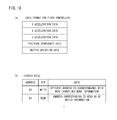
- a data format for the first controller is shown in Figure 18(A) .
- a format of access data to be used in the mode control in the first controller is shown in Figure 18(B) .
- a mode control and a mode transition in the first controller 34 are shown in Figure 19(A) and Figure 19(B) , respectively.
- the mode control and the mode transition are similar to those performed when the gyro sensor unit 100 is connected to the conventional first controller.
- the mode control and the mode transition which are performed when the gyro sensor unit 100 is connected to the first controller 34 are shown in Figure 20(A) and Figure 20(B) , respectively.
- a gyro mode and a gyro & second controller mode are equivalent to (or absorbed in) a standby mode and a bypass mode.
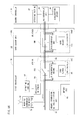
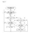
- a microcomputer control by the first controller 34 is shown in Figure 21- Figure 24 .
- a game system 10 of one embodiment of the present invention includes a game apparatus 12 and a controller 14.
- the game apparatus 12 is a game console.
- the controller 14 is an input device or an operating device by a user or a player.
- the game apparatus 12 and the controller 14 are connected wirelessly.
- the game apparatus 12 includes a roughly rectangular parallelepiped housing 16, and the housing 16 is furnished with a disk slot 18 and a memory card slot cover 20 on a front surface.
- An optical disk 66 ( Figure 11 ) as one example of an information storage medium storing game program and data, etc. is inserted from the disk slot 18 to be loaded into a disk drive 54 (see Figure 11 ) within the housing 16.
- Inside the external memory card slot cover 20 is provided with a connector for external memory card 62 ( Figure 11 ) through which a memory card (not shown) is inserted.
- the external memory card is employed for loading the game program, etc.
- storing the game data described above may be performed on an internal memory such as a flash memory in place of the external memory card.
- the game apparatus 12 has an AV cable connector (not illustrated) on a rear surface of the housing 16, and by means of the connector, the game apparatus 12 is connected to a monitor (display) 30 via an AV cable 28.
- the monitor 30 is typically a color television receiver, and through the AV cable 28, a video signal from the game apparatus 12 is input to a video input terminal of the color television, and a sound signal is input to a sound input terminal thereof. Accordingly, a game image of a three-dimensional (3D) video game, for example, is displayed on the screen of the color television (monitor) 30, and a stereo game sound, such as a game music, a sound effect is output from integrated speakers 32.
- 3D three-dimensional
- a marker unit 22 having two infrared ray LEDs (markers) 22a and 22b is provided around the monitor 30 (upper side of the monitor 30 in this embodiment.
- Each of the markers 22a and 22b outputs infrared rays ahead of the monitor 30.
- the power of the game apparatus 12 is applied by means of a general AC adapter (not illustrated).
- the AC adapter is connected to a standard wall outlet for home use, and transforms the house current to a low DC voltage signal suitable for driving the game apparatus 12.
- a battery may be utilized as a power supply.
- the marker unit 22 is connected with the game apparatus 12 through a power-supply wire not shown, and is supplied with power from the game apparatus 12.
- the controller 14 which is described in detail later, includes a first controller 34 and a second controller 36 each capable of being held with one hand and a gyro sensor unit 100 to be attached to the first controller 34.
- a connector 42 ( Figure 2(A) , Figure 3 , Figure 13 and Figure 14 ) is provided, and at an end of a cable 38 extending from the rear end of the second controller 36, a connector 40 ( Figure 5, Figure 6 , Figure 13 , and Figure 14 ) is provided, and on a front end surface and a rear end surface of the gyro sensor unit 100, connectors 106 and 108 ( Figure 7(A), Figure 7(B) , Figure 13 and Figure 14 ) are respectively provided.
- the connector 106 at the front end surface of the gyro sensor unit 100 is connectable to the connector 42 of the first controller 34, and the connector 40 of the second controller 36 is connectable to the connector 42 of the first controller 34 or the connector 108 at the rear end surface of the gyro sensor unit 100.
- the gyro sensor unit 100 is not necessary, and it is preferable that the second controller 36 is used to be directly connected to the first controller 34 without interposing the gyro sensor unit 100, but in this embodiment, in order to explain a case that the gyro sensor unit 100 is erroneously connected is, the gyro sensor unit 100 is connected.
- the gyro sensor unit 100 By connecting the connector 106 to the connector 42, the gyro sensor unit 100 is physically and electrically connected to the first controller 34. However, from the gyro sensor unit 100 thus attached (connected as a single unit) to the first controller 34, angular velocity data indicating an angular velocity of the first controller 34 is not output (described in detail later). If the gyro sensor unit 100 is attached to the first controller as described in the Patent Document 1, angular velocity data is output.
- the connector 40 of the second controller 36 is connected to the connector 108 at the rear end surface of the gyro sensor unit 100. That is, the connector 42 has a structure selectively connectable to either of the connector 106 or the connector 40, and the connector 40 has a structure of selectively connectable to either of the connector 42 or the connector 108. Accordingly, the connector 106 and the connector 108 provided to the gyro sensor unit 100 cannot actually be connected because of being a part of the same housing, but have shapes connectable with each other. Input data from the second controller 36 is applied to the first controller 34 via the cable 38 and the gyro sensor unit 100.
- the first controller 34 transmits controller data including input data from the first controller 34 itself, and input data from the second controller 36 to the game apparatus 12.
- the input data of the first controller 34 includes angular velocity data from the gyro sensor 85 ( Figure 3 , Figure 13 - Figure 15 ) integrated in the first controller 34 itself (described in detail later).
- operation data or input data from the second controller 36 are applied to the first controller 34 via the cable 38, and the first controller 34 transmits controller data including the input data from the first controller 34 itself and the input data from the second controller 36 to the game apparatus 12.
- an amount of the data to be transmitted at a time may sometimes be designed so as not be added, but the microcomputer 94 of the first controller 34 can transmit data by alternately transmitting the angular velocity data from the gyro sensor 85 and the input data from the second controller 36 to the wireless module 76.
- a user first turns the power of the game apparatus 12 on for playing the game (or another application), then selects an appropriate optical disk 66 storing a video game (or another application the player wants to play), and loads the optical disk 66 into the disk drive 54 through the disk slot 18 of the game apparatus 12.
- the game apparatus 12 starts to execute a video game or another application on the basis of the software stored in the optical disk 66.
- the user operates the controller 14 in order to apply an input to the game apparatus 12.
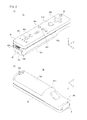
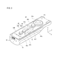
- Figure 2 shows one example of an appearance of the first controller 34.
- Figure 2(A) is a perspective view of the first controller 34 as seeing it from above rear
- Figure 2(B) is a perspective view of the first controller 34 as seeing it from below front.
- the first controller 34 has a housing 78 formed by plastic molding, for example.
- the housing 78 is formed into an approximately rectangular parallelepiped shape regarding a back and forth direction (Z-axis direction shown) as a longitudinal direction, and has a size small enough to be held by one hand of a child and an adult.
- the housing 78 has a length or a width approximately the same as that of a palm of a person. The player can perform a game operation by means of the first controller 34, specifically, by pushing the buttons provided on it and by changing a position and a direction of the first controller 34 itself.
- the housing 78 is provided with a plurality of operation buttons. That is, on the top surface of the housing 78, a cross key 80a, an X button 80b, a Y button 80c, an A button 80d, a select switch 80e, a menu switch 80f, and a start button 80g are provided. Meanwhile, on the bottom surface of the housing 78, a concave portion is formed, and on the reward inclined surface of the concave portion, a B button 80h is provided. Each of the buttons (switches) 80a-80h is assigned an appropriate function depending on a game program to be executed by the game apparatus 12.
- the housing 78 has a power switch 80i for turning on and off the power of the main body of the game apparatus 12 from a remote place on a top surface.
- the respective buttons (switches) provided on the first controller 34 may inclusively be indicated as an operating means or an input means with the use of the reference numeral 80.
- the imaged information arithmetic section 81 is made up of a camera for imaging infrared rays and an arithmetic operation portion for calculating coordinates of imaged objects within an image, and captures an object scene including the above-described markers 22a and 22b by the infrared rays to calculate position coordinates of the markers 22a and 22b within the object scene.
- the above-described connector 42 is provided on the rear surface of the housing 78.
- the connector 42 is utilized for connecting other equipment to the first controller 34.
- the connector 42 is connected with the connector 40 of the second controller 36 or the connector 106 of the gyro sensor unit 100.
- a pair of through holes 82a and 82b is formed in such positions as to be symmetrically with each other (X-axis direction) about the connector 42.
- the pair of through holes 82a and 82b is for being inserted with hooks 112Fa and 112Fb ( Figure 7(A) ) to securing the gyro sensor unit 100 at the rear surface of the housing 78.
- a through hole 82c for attaching a strap 24 ( Figure 6 ) is also provided.
- the first controller 34 includes the substrate 34B within the housing 78, and at one end of this substrate 34B in the longitudinal direction, the connector 42 described before is attached.
- the cross key 80a, the X button 80b, the Y button 80c, the A button 80d, the select switch 80e, the menu switch 80f, and the start switch 80g as explained before are assembled.
- the acceleration sensor 84 as described before is assembled between the cross key 80a and the X button 80b and between the start switch 80g and the select switch 80e, the gyro sensor 85 is arranged between the acceleration sensor 84 and the X button 80b, and the wireless module 76 is arranged at the right of the gyro sensor 85 in the width direction.
- the various buttons (switches), sensors and modules are connected to the microcomputer 94 ( Figure 13 ) which constructs a controller circuit by proper wiring (not illustrated).
- the acceleration sensor 84 is a three-axis linear accelerometer for detecting a linear acceleration in three-axis directions of X, Y and Z.
- the gyro sensor 85 is made up of two chips including one-axis gyro sensor 85a and a two-axis gyro sensor 85b.
- the gyro sensor 85a is for detecting an angular velocity (angular velocity about the Y axis) relating to a yaw angle
- the gyro sensor 85b is detecting two angular velocities (angular velocity about the Z axis and angular velocity about the X axis) relating to a roll angle and a pitch angle.
- the gyro sensors 85a and 85b are vertically aligned on a main top surface of the substrate 34B.
- the gyro sensor may be one three-axis gyro sensor or three one-axis gyro sensors.
- the direction of the arrangement of the gyro sensor 85 is the same as the direction of the gyro sensor 104 when the gyro sensor unit 100 is connected as described in detail.
- the gyro sensor is for detecting an angular velocity, and thus, the physical quantity is not changed depending on the position, and therefore, this may be arranged at any positions, for example, at the opposite end of the substrate.
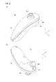
- Figure 4 is an illustrative view showing one example of an appearance of the second controller 36 itself.
- Figure 4(A) is a perspective view of the second controller 36 as seeing it from above rear
- Figure 4(B) is a perspective view of the second controller 36 as seeing it from below front.
- the cable 38 of the second controller 36 is omitted.
- the second controller 36 has a housing 86 formed by plastic molding, for example.
- the housing 86 is formed into an approximately thin long elliptical shape in the forward and backward direction (Z-axis direction) when viewed from plane, and the width of the right and left direction (X-axis direction) at the rear end is narrower than that of the front end. Furthermore, the housing 86 has a curved shape as a whole when viewed from a side, and downwardly curved from a horizontal portion at the front end to the rear end.
- the housing 86 has a size small enough to be held by one hand of a child or an adult similar to the first controller 34 as a whole, and has a longitudinal length (in the Z-axis direction) slightly shorter than that of the housing 78 of the first controller 34. Even with the second controller 36, the player can perform a game operation by operating buttons and a stick, and by changing a position and a direction of the controller itself.
- an analog joystick 88a is provided at the front end of the top surface of the housing 86.
- a front edge slightly inclined backward is provided, and on the front edge, a C button 88b and a Z button 88c are vertically (Y-axis direction in Figure 4 ) provided.
- the analog joystick 88a and the respective buttons 88b and 88c are assigned appropriate functions according to a game program to be executed by the game apparatus 12.
- the analog joystick 88a and the respective buttons 88b and 88c provided to the second controller 36 may be inclusively denoted by means of the reference numeral 88.
- an acceleration sensor 90 ( Figure 3 ) is provided inside the housing 86 of the second controller 36.
- an acceleration sensor 90 an acceleration sensor similar to the acceleration sensor 84 in the first controller 34 is applied. More specifically, a three-axis acceleration sensor is applied in this embodiment, and detects accelerations in each of the three axis directions such as an up and down direction (Y-axial direction shown), a right and left direction (X-axial direction shown), and a forward and backward direction (Z-axial direction shown) of the second controller 36. Accordingly, similar to the case of the first controller 34, proper arithmetic process is performed on the detected accelerations to thereby calculate a tilt and a rotation of the second controller 36 and an attitude of the acceleration sensor 90 in the direction of gravity. Furthermore, it is possible to calculate a motion applied to the first controller 34 by swinging, etc. as with the case of the second controller 36.
- Figure 5 shows one example of an appearance of the connector 40 of the second controller 36.
- Figure 5 is a perspective view of the connector 40 as seeing it from below front.
- the cable 38 is omitted.
- the connector 40 has a housing 142 formed by a plastics molding, for example.
- a hook 144 is provided at the bottom surface of the housing 142.
- the hook 144 is for intrinsically hanging and retaining a cord of the strap 24 attached to the first controller 34 when the connector 40 is directly connected to the first controller 34 (or the connector 42) as shown in Figure 6 . By hanging and retaining the cord of the strap 24 on the hook 144, the connectors are more securely fixed.
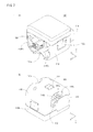
- Figure 7 shows one example of an appearance of the gyro sensor unit 100.
- Figure 7(A) is a perspective view of the gyro sensor unit 100 as seeing it from above front
- Figure 7(B) is a perspective view of the gyro sensor unit 100 as seeing it from rear back.
- the gyro sensor unit 100 has a housing 110 formed by a plastics molding, for example.
- the housing 110 has an appropriately rectangular parallelepiped shape, has a length 1/5 of the length of the housing 78 of the first controller 34, and has a width and a thickness approximately the same as those of the housing 78.
- the player can play a game operation by changing a position and a direction of the first controller 34 itself even if the first controller 34 is attached with the gyro sensor unit 100.
- the above-described connectors 106 and 108 are respectively provided, on the side surfaces of the housing 110, a pair of release buttons 112a and 112b are provided, and the bottom surface of the housing 110, a lock switch 114 is provided.
- An approximately sphere concave portion 110a is provided from the end of the front surface of the housing 110 to the bottom surface such that the through hole 82c for the strap 24 is exposed in a state that the first controller 34 is attached with the gyro sensor unit 100 ( Figure 9 ).
- the pair of release buttons 112a and 112b, and a pair of hooks 112Fa and 112Fb which are respectively associated with the release buttons 112a and 112b are provided on a front surface of the housing 110 at positions symmetrically with each other in a horizontal direction (X-axis direction) about the connector 106.
- the pair of hooks 112Fa and 112Fb are inserted to the pair of through holes 82a and 82b ( Figure 2(A) ) at the rear surface of the housing 78 such that the pawls of the hooks 112Fa and 112Fb are engaged with the inner wall of the housing 78.
- the gyro sensor unit 100 is fixed to the rear surface of the first controller 34.
- Figure 9 shows the gyro sensor unit 100 thus attached to the first controller 34.
- the pair of release buttons 112a and 112b are pushed in this state, the engagement of the pawls are released to allow the gyro sensor unit 100 to be detached from the first controller 34.
- a lock switch 114 is a sliding switch for locking such the release buttons 112a and 112b.
- the release buttons 112a and 112b cannot be pushed (locked state) when the lock switch 114 is in a first position (toward the rear side, for example), and the release buttons 112a and 112b can be pushed (released state) when the lock switch 114 is in a second position (toward the front, for example).
- locking springs 118a and 118b ( Figure 8 ) are provided and constructed so as to be repulsed when the release button 112a and 112b are pushed, and so as to maintain the engaged state when the release button 112a and 112b are not pushed.
- the user has to push the release buttons 112a and 112b after sliding the lock switch 114 from the first position to the second position.
- a concave portion 110b capable of housing the connector cover 116 to be attached to the connector 108 is provided on the periphery of the connector 108.
- the connector cover 116 has a narrow thin (that is, can be bended) protrusion 116a extending in a forward and backward (Z-axis direction) direction on the one end of the main surface. The end portion of the protrusion 116a is engaged with the housing 110, and the connector cover 116 is captive from the housing 110 even in a state that it is removed from the connector 108.
- the connector cover 116 has a narrow thick (that is, is hard to bend) protrusion 116b extending in a right and left direction (X-axis direction) on the other end of the main surface.
- the thickness (height of the Z-axis direction) of the protrusion 116b is approximately the same as the thickness (height of the Y-axis direction) of the hook 144 ( Figure 5 ) provided to the connector 40 of the second controller 36.
- the main surface of the connector cover 116 is made level to be engaged with the side surface of the hook 144 of the protrusion 116b as shown in Figure 10 .
- Figure 8 shows one example of a structure of the gyro sensor unit 100.
- the gyro sensor unit 100 also has a gyro substrate 120 and a support member 122 in addition to the above-described housing 110, connectors 106 and 108, release buttons 112a and 112b, hooks 112Fa and 112Fb, lock switch 114, connector cover 116 and locking springs 118a and 118b.
- the gyro substrate 120 is connected to each of the connectors 106 and 108 by a signal wire, and the support member 122 supports the gyro substrate 120 and the connectors 106 and 108.
- the gyro substrate 120 is provided with a gyro sensor 104.
- the gyro sensor 104 is made up of two chips including one-axis gyro sensor 104a and two-axis gyro sensor 104b.
- the gyro sensor 104a is for detecting an angular velocity relating to a yaw angle (angular velocity about the Y axis)
- the gyro sensor 104b is for detecting two angular velocities relating to a roll angle and a pitch angle (angular velocity about the Z axis and angular velocity about the X axis).
- the gyro sensors 104a and 104b are arranged horizontally on a top surface 120a of the gyro substrate 120.
- the arrangement of the gyro sensors 104a and 104b is not restricted to that shown in Figure 8 .
- the gyro sensor 104a is horizontally provided on one of the top surface 120a and the bottom surface 120b of the gyro substrate 120 while the gyro sensor 104b is horizontally provided on the other of the top surface 120a and the bottom surface 120b of the gyro substrate 120 so as to be opposed to the gyro sensor 104a with the gyro substrate 120 therebetween.
- the gyro sensor 104a is vertically provided on one of the top surface 120a and the bottom surface 120b of the gyro substrate 120 while the gyro sensor 104b is horizontally provided on the other of the top surface 120a and the bottom surface 120b of the gyro substrate 120.
- the gyro sensor 104 is not restricted to be made up of two chips, may be made up of three one-axis gyro sensors (three chips), or may be made up of one three-axis gyro sensor (one chip). In either case, a position and a direction of each of the chips are decided so as to properly detect the above-described three angular velocities.
- the gyro sensor 104 may be made up of one two-axis gyro sensor, or may be mad up of one or two one-axis gyro sensor.
- This modified example may be applied to the gyro sensor 85 integrated in the first controller 34.
- the shapes of the first controller 34 shown in Figure 2 , the second controller 36 shown in Figure 4 , the connector 40 shown in Figure 5 , and the gyro sensor unit 100 shown in Figure 7 , and the shape, the number and the setting position of the button (switch or stick, etc.) are merely one example, and may be changed to another shape, number and setting position, etc. as necessary.
- the senor is a gyro sensor (angular velocity sensor) in a preferred embodiment, but may be other motion sensors, such as an acceleration sensor, a velocity sensor, a displacement sensor, a rotation angle sensor, etc.
- motion sensors such as an acceleration sensor, a velocity sensor, a displacement sensor, a rotation angle sensor, etc.
- a slant sensor an image sensor, an optical sensor, a pressure sensor, a magnetic sensor, a temperature sensor, etc.
- a pressure sensor a magnetic sensor
- a temperature sensor etc.
- the sensor can be added to the operating device while another device conventionally connected to the operating device is utilized as it is.
- the power source of the controller 14 is applied by a battery (not illustrated) which is replaceably accommodated in the first controller 34.
- the power is supplied to the second controller 36 via the connector 40 and the cable 38. If the gyro sensor unit 100 is connected to the first controller 34, the power is supplied to the gyro sensor unit 100 via the connectors 42 and 106. Alternatively, if the second controller 36 is connected to the gyro sensor unit 100, a part of the power supplied from the first controller 34 to the gyro sensor unit 100 is also applied to the second controller 36 via the connector 108, the connector 40 and the cable 38.
- FIG 11 shows a block diagram showing an electric configuration of the video game system 10. Although illustration is omitted, respective components within the housing 16 are mounted on the printed-circuit board.
- the game apparatus 12 is provided with a CPU 44 functioning as a game processor.
- the CPU 44 is also connected with a system LSI 64.
- the system LSI 64 is connected with an external main memory 46, a ROM/RTC 48, a disk drive 54 and an AV IC 56.
- the external main memory 46 is utilized as a work area and a buffer area of the CPU 44 by storing programs such as a game program, etc. and various data.
- the ROM/RTC 48 which is a so-called boot ROM, is incorporated with a program for activating the game apparatus 12, and is provided with a time circuit for counting a time.
- the disk drive 54 reads program, texture data, etc. from the optical disk 66, and writes them in an internal main memory 64e described later or the external main memory 46 under the control of the CPU 44.
- the system LSI 64 is provided with an input-output processor 64a, a GPU (Graphics Processor Unit) 64b, a DSP (Digital Signal Processor) 64c, a VRAM 64d and an internal main memory 64e, and these are connected with one another by internal buses although illustration is omitted.
- the input-output processor (I/O processor) 64a executes transmission and reception of data and executes download of the data.
- the GPU 64b is made up of a part of a drawing means, and receives a graphics command (construction command) from the CPU 44 to generate game image data according to the command. Additionally, the CPU 44 applies an image generating program required for generating game image data to the GPU 64b in addition to the graphics command.
- the GPU 64b is connected with the VRAM 64d as described above.
- the GPU 64b accesses the VRAM 64d to acquire data (image data: data such as polygon data, texture data, etc.) required to execute the construction command.
- image data data such as polygon data, texture data, etc.
- the CPU 44 writes image data required for drawing to the VRAM 64d via the GPU 64b.
- the GPU 64b accesses the VRAM 64d to produce game image data for drawing.
- the DSP 64c functions as an audio processor, and generates audio data corresponding to a sound, a voice, music, or the like to be output from the speaker 32 by means of the sound data and the sound wave (tone) data stored in the internal main memory 64e and the external main memory 46.
- the game image data and audio data which are generated as described above are read by the AV IC 56 and output to the monitor 30 and the speaker 32 via the AV connector 58. Accordingly, a game screen is displayed on the monitor 30, and a sound (music) necessary for the game is output from the speaker 32.
- the input-output processor 64a is connected with a flash memory 43, a wireless communication module 50 and a wireless controller module 52, and is also connected with an expansion connector 60 and a connector for external memory card 62.
- the wireless communication module 50 is connected with an antenna 50a
- the wireless controller module 52 is connected with an antenna 52a.
- the input-output processor 64a can communicate with other game apparatuses and various servers to be connected to a network (not shown) via the wireless communication module 50. It should be noted that it is possible to directly communicate with another game apparatus without going through the network.
- the input-output processor 64a periodically accesses the flash memory 43 to detect the presence or absence of data (referred to as data to be transmitted) being required to be transmitted to a network, and transmits it to the network via the wireless communication module 50 and the antenna 50a in a case that data to be transmitted is present. Furthermore, the input-output processor 64a receives data (referred to as received data) transmitted from another game apparatuses via the network, the antenna 50a and the wireless communication module 50, and stores the received data in the flash memory 43.
- the input-output processor 64a receives data (download data) downloaded from the download server (not shown) via the network, the antenna 50a and the wireless communication module 50, and stores the download data in the flash memory 43.
- the input-output processor 64a receives input data transmitted from the controller 14 via the antenna 52a and the wireless controller module 52, and (temporarily) stores it in the buffer area of the internal main memory 64e or the external main memory 46.
- the input data is erased from the buffer area after being utilized in the processing by the CPU 44 (game processing, for example).
- the wireless controller module 52 makes communications with the controller 14 in accordance with the Bluetooth standard. This makes it possible for the game apparatus 12 to not only acquire data from the controller 14 but also to transmit a predetermined command to the controller 14 and control a motion of the controller 14 from the game apparatus 12.
- the input-output processor 64a is connected with the expansion connector 60 and the connector for external memory card 62.
- the expansion connector 60 is a connector for interfaces, such as USB, SCSI, etc., and capable of connecting medium such as an external storage and peripheral devices such as another controller different form the controller 14.
- the cable LAN can be utilized in place of the wireless communication module 50.
- the connector for memory card 62 can be connected with an external storage like a memory card 38.
- the input-output processor 64a accesses the external storage via the expansion connector 60 and the connector for external memory card 62 to store and read the data in and from the same.
- the game apparatus 12 (housing 16) is provided with the power button 20a, the reset button 20b and the eject button 20c as shown in Figure as well.
- the power button 20a is connected with the system LSI 64.
- the system LSI 64 When the power button 20a is turned on, the system LSI 64 is set to a mode of a normal energized state in which the respective components of the game apparatus 12 are supplied with power through an AC adapter not shown.
- the reset button 20b is also connected with the system LSI 64.
- the system LSI 64 activates a started-up program of the game apparatus 12.
- the eject button 20c is connected to the disk drive 54.
- the optical disk 66 is ejected from the disk drive 54.
- Figure 13 shows one example of an overall electric configuration of the controller 14 when the first controller 34 and the second controller 36 are connected (without interposing the gyro sensor unit 100).
- the first controller 34 includes the wireless communication module 76 therein, and the wireless communication module 76 is connected with the operating portion 80 and the acceleration sensor 84.
- the wireless communication module is connected to a serial bus 95 being a common bus, and the serial bus 95 is connected with the imaged information arithmetic section 81, other devices, such as a memory 96, etc.
- the memory 96 is constructed by an EEPROM, for example, and stores device information of the first controller, and a program, data, etc. for operating the wireless communication module 76, the microcomputer 94, etc.
- the serial bus 95 can utilize a serial bus like I2C, etc., for example.
- a microcomputer 89 of the second controller 36 is connected to one end of the serial bus 95.
- the former microcomputer 94 is connected with the gyro sensor 85, and the latter microcomputer 89 is connected with the operating portion 88 and the acceleration sensor 90.
- Each device connected to the serial bus 95 is assigned an address on the serial bus 95.
- a #1 address, a #2 address, and a #3 address, a #4 address are assigned to the imaged information arithmetic section 81, the memory 96, the microcomputer 94, and the microcomputer 89, respectively.
- the #3 address is a special address used only for a call control (see Figure 21 , Figure 22 and Figure 23 ) for calling a gyro function
- the #4 address being a normal address is assigned to an arbitrary expansion device in the main control (see Figure 21 , Figure 24 ).
- a state in which the #4 address is assigned to the microcomputer 94 is a state that the integrated gyro sensor 85 is activated, that is, corresponds to the gyro mode or the gyro & second controller mode
- a state in which the #3 address is assigned to the microcomputer 94 is a state that the integrated gyro sensor 85 is in a sleep mode, that is, corresponds to the standby mode or the bypass mode.
- the gyro mode is a mode in which a gyro function is used, and the second controller is not connected.
- the gyro & second controller mode is a mode in which both of the gyro function and the second controller are used.
- the standby mode is a mode in which the gyro function is not used, and the second controller is not connected.
- the bypass mode is a mode in which the gyro function is not used, and the second controller is used. Depending on the presence or absence of utilization the gyro function and the presence or absence of utilization the second controller, control can be performed among the aforementioned four modes.
- each microcomputer in the gyro & second controller mode, the plurality of microcomputers each of which is assigned the #4 address as an address, that is, the microcomputer 94, the microcomputers 102 and/or 89 are in a state of being connected to the serial bus 95.
- each microcomputer can be identified on the basis of gyro/second controller identifying information (see Figure 17 ).
- the wireless module 76 is connected to the microcomputer 94 by an Attach pin, and the microcomputer 94 is connected to the connector 42 by an Attach pin.
- the wireless module 76 can know whether or not the connector 42 is connected with the device, such as the gyro sensor unit 100, the second controller 36, etc. with reference to the value of Attach.
- the switch SW1 is turned on (Connect) in a mode in which the gyro sensor 85 is not used (standby mode or bypass mode) under the control of the microcomputer 94, and is turned off (Disconnect) in a mode in which the gyro sensor 85 is used (gyro mode or gyro & second controller mode) (see Figure 19(A) ).
- the operating portion 80 indicates the above-described operation buttons or operation switches 80a-80i.
- data indicating the operation is output to the wireless communication module 76.
- Data indicating the acceleration detected by the acceleration sensor 84 is also output to the wireless communication module 76.
- the acceleration sensor 84 has a sampling period being in the order of 200 frames per second at the maximum, for example.
- the gyro sensor 85 indicates the above-described gyro sensors 85a and 85b, and has a sampling period similar to that of the acceleration sensor 84, for example.
- the microcomputer 94 outputs data indicating the angular velocity detected by the gyro sensor 85 to the wireless communication module 76 through the serial bus 95.
- the operating portion 88 shows the above-described stick 88a and operation buttons 88b, 88c.
- the operating portion 88 When the operating portion 88 is operated, in a case that the switch SW1 is turned on, the data indicating the operation (operation data) is output to the wireless communication module 76 from the microcomputer 89 through the serial bus 95. On the other hand, in a case that the switch SW1 is turned off, the operation data is applied to the microcomputer 94 through the serial bus 95, and the microcomputer 94 outputs the operation data to the wireless communication module 76 through the serial bus 95.
- the acceleration sensor 90 has a sampling period similar to that of the acceleration sensor 84.
- the data indicating the acceleration thus detected is also output to the wireless communication module 76 through a bypass on the side of the switch SW1 by the microcomputer 89 in a case that the switch SW1 is turned on, and output to the wireless communication module 76 via the microcomputer 94 when the switch SW1 is turned off, similar to the case of the operation data.
- each output to the above-described wireless communication module 76 is executed at a cycle of 1/200 seconds, for example. Accordingly, during arbitrary 1/200 seconds, operation data from the operating portion 80, position coordinate data from the imaged information arithmetic section 81, acceleration data from the acceleration sensor 84, angular velocity data from the gyro sensor 85, operation data from the operating portion 88, and acceleration data from the acceleration sensor 90 are output to the communication unit 76 once for each of them.
- the switch SW1 and the gyro sensor 85 are added to the conventional first controller, and the microcomputer 94 control them to thereby add the gyro function to the first controller 34.
- An important part being made up of the switch SW1, the gyro sensor 85 and the microcomputer 94 is called a "gyro controller 85C" below.
- Figure 14 shows one example of an overall electric configuration of the controller 14 when the first controller 34 and the second controller 36 are connected via the gyro sensor unit.
- the gyro sensor unit 100 includes a gyro controller 104C.
- the gyro controller 104C is made up of a switch SW2, the gyro sensor 104 and the microcomputer 102.
- the gyro sensor 104 shows the above-described gyro sensors 104a and 104b, and has a sampling period similar to that of the acceleration sensor 84, for example.
- the microcomputer 102 turns the switch SW2 on (Connect) to place the gyro sensor in a sleep state in the standby mode or the bypass mode, and turns the switch SW2 off (Disconnect) to output the data indicating the angular velocity detected by the gyro sensor 104 to the wireless communication module 76 through the serial bus 95 in the gyro mode or the gyro & second controller mode.
- the switch SW2 and the microcomputer 102 which are arranged in parallel with each other are interposed between the first controller 34 (the microcomputer 94 thereof) and the second controller 36 (the microcomputer 89 thereof) (on the serial bus 95).
- the microcomputer 94 controls the switch SW2 and the gyro sensor 104 through the microcomputer 102 to cause the switch SW2 to be placed in an initial state, that is, in an ON (Connect) state irrespective of the modes as shown in Figure 20 and cause the gyro sensor 104 to be placed in the sleep mode (power off state) irrespective of the modes.
- FIG 15 shows an important part of the first controller, that is, a configuration of the gyro controller 85C shown in Figure 13 or Figure 14 .
- Each of the above-described connector 42, connector 106, connector 108 and connector 40 is a connector of six pins, for example, in which an Attach pin for controlling a variable "Attach” indicating a connected state between the connectors is included.
- the Attach pin is changed between "Low” indicating that the connectors are not connected, and "High” indicating that the connectors arc connected.
- the Attach pin on the side of the wireless module 76 is called an "Attach1"
- the Attach pin on the side of the connector 42 is called an "Attach2" when seen from the microcomputer 94.
- the other two pins out of the aforementioned six pins are assigned the serial bus 95, and the gyro controller 85C further includes a bus switch SW1 for making connection/isolation between the serial bus 95 on the side of the wireless module 76 and the serial bus 95 on the side of the connector 42.
- the microcomputer 94 includes two kinds of A/D conversion circuits 94a and 94b. Angular velocity signals about the three axes output from the gyro sensor 85 are applied to each of the A/D conversion circuits 94a and 94b.
- A/D conversion circuit 94a A/D converting processing of a high angular velocity mode for regarding all the detection range by the gyro sensor 85 ( ⁇ 360° /sec) as a target, for example, is executed
- A/D conversion circuit 94b A/D converting processing of a low angular velocity mode for regarding a part of the detection range by the gyro sensor 85 ( ⁇ 90° /sec, for example) as a target is executed.
- the microcomputer 94 outputs any one of the two kinds results of the A/D conversion as angular velocity data.
- the microcomputer 94 first determines whether or not with respect to the angular velocity data of the low angular velocity mode, the value A falls within the range of a first threshold value Th1 to a second threshold value Th2 (>Th1), that is, a condition "Th1 ⁇ A ⁇ Th2" is satisfied, for each of the axis, that is, the yaw axis, the roll axis, and the pitch axis.
- Th1 a first threshold value
- Th2 >Th1
- any one of the low angular velocity mode and the high angular velocity mode is selected.
- the angular velocity data according to the mode selected for each axis is output along with the mode information indicating the selected mode. That is, by changing accuracy of the data depending on the angular velocity, it is possible to output data with high accuracy at low speeds even if the data amount is equal.
- Figure 16 shows an important part of the gyro sensor unit 100, that is, the gyro controller 104C shown in Figure 14 .
- the configuration of the gyro controller 104C is roughly equivalent to the configuration of the gyro controller 85C as described above except for the content of the control of the microcomputer.
- an Attach1 and an Attach2 are on the side of the first controller 34 (microcomputer 94) and on the side of the second controller 36 (microcomputer 89), respectively when seen from the microcomputer 102.
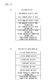
- Figure 17 shows a data format handled by the gyro controller 85C in the first controller 34 (output from the microcomputer 94 to the wireless module 76).
- Figure 17(A) shows a data format for gyro
- Figure 17(B) shows a data format for second controller.
- these formats are common to that of the data dealt by the gyro controller 104C in the gyro sensor unit 100.
- the data for gyro includes yaw angular velocity data, roll angular velocity data and pitch angular velocity data, and yaw angular velocity mode information, roll angular velocity mode information and pitch angular velocity mode information, and second connector connection information and gyro/second controller identifying information.
- the yaw angular velocity data, the roll angular velocity data and the pitch angular velocity data are respectively obtained by performing an A/D conversion on a yaw angular velocity signal, a roll angular velocity signal and a pitch angular velocity signal which are output from the gyro sensor 104.
- the yaw angular velocity mode information, the roll angular velocity mode information and the pitch angular velocity mode information each is information of one bit indicating a corresponding mode of each of the angular velocity data, and changed between "0" corresponding to the high angular velocity mode and "1" corresponding to the low angular velocity mode.
- the second controller connection information is information of one bit for indicating whether or not the connector 42 or 108 is connected to the second controller 36, and is changed between "0" indicating a non-connection and "1" indicating a connection.
- the gyro/second controller identifying information is information of one bit for identifying whether the data is data output from the gyro sensor 85 or 104 or the data output from the second controller 36, and is changed between "1" indicating that this is from the gyro sensor 85 or 104 and "0" indicating that this is from the second controller 36.
- the data from the second controller includes X stick operation data and Z stick operation data respectively indicating a stick operation in the right and left direction (X-axis direction) and a stick operation in the forward and reward direction (Z-axis direction), and X acceleration data, Y acceleration data and Z acceleration data respectively indicating an acceleration in the X-axis direction, an acceleration in the Y-axis direction and an acceleration in the Z-axis direction, and button operation data, second connector connection information, and gyro/second controller identifying information.
- the microcomputer 94 alternately outputs data for gyro according to the format shown in Figure 17(A) and data for second controller according to the format shown in Figure 17(B) to the wireless module 76 at a cycle of 1/200 seconds, that is, at a cycle of 1/100 seconds as to the one format. This is much shorter than the cycle of 1/60 seconds as a general processing period for game processing, etc., and therefore, even if the data is alternately output, both of the data can be simultaneously used for one frame in the game processing.
- the wireless module 76 includes a microcomputer 76C, a memory 76R, etc., and transmits obtained data to the game apparatus 12 via the antenna 98 and receives data from the game apparatus 12 via the antenna 98 by using the memory 76R as a memory area (working area and buffer area) under the control of the microcomputer 76C.
- the data output from the microcomputer 94 to the wireless module 76 is temporarily stored in the memory 76R through the microcomputer 76C.
- the data output from the operating portion 80, the imaged information arithmetic section 81 and the acceleration sensor 84 within the first controller 34 to the wireless module 76 are also temporarily stored in the memory 76R.
- the microcomputer 76C outputs the data stored in the memory 72R to the wireless module 76 as controller data when a transmission timing to the game apparatus 12 has come.
- the controller data includes the data for first controller shown in Figure 18 (A) in addition to the data for gyro shown in Figure 17(A) and/or the data for second controller shown in Figure 17(B) .
- the data for first controller includes X acceleration data, Y acceleration data and Z acceleration data based on an output from the acceleration sensor 84, position coordinate data based on an output from the imaged information arithmetic section 81, and button operation data based on an output from the operating portion 80.
- the wireless module 76 modulates a carrier at a predetermined frequency by the controller data, and emits its weak radio wave signal from the antenna 98 by using a short-range wireless communication technique, such as Bluetooth (trademarks). Namely, the controller data is modulated to the weak radio wave signal by the wireless module 76 and transmitted from the first controller 34.
- the weak radio wave signal is received by the wireless controller module 52 of the game apparatus 12.
- the weak radio wave thus received is subjected to demodulating and decoding processing, so that the game apparatus 12 can obtain the controller data.
- the CPU 44 of the game apparatus 12 performs the game processing on the basis of the controller data obtained from the controller 14.
- the wireless communication between the first controller 34 and the game apparatus 12 may be executed according to another standard, such as a wireless LAN, etc without being restricted to the short distance wireless communication.
- a user can make an input to an application like a game, or the like by moving the controller 14 itself other than execution of a button operation.
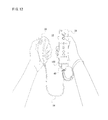
- the user holds the first controller 34 (specifically, holding portion 78a of the housing 78: Figure 2 ) with the right hand and the second controller 36 with the left hand as shown in Figure 12 .
- the first controller 34 includes the acceleration sensor 84 for detecting accelerations in the three-axis directions, and the second controller 36 also includes the similar acceleration sensor 90.
- the first controller 34 further includes the gyro sensor 85 for detecting an angular velocity about the three-axes.
- acceleration values in the three-axis directions indicating the movements of the first controller itself and angular velocity value about the three-axes are detected by the acceleration sensor 84 and the gyro sensor 85, and acceleration values in the three-axis directions indicating the movement of the second controller itself are detected by the acceleration sensor 90.
- the controller data from the controller 14 is received by the input-output processor 64a via the antenna 52a and the wireless controller module 52, and the received controller data is written to a buffer area of the internal main memory 64e or the external main memory 46.
- the CPU 44 reads the controller data stored in the buffer area of the internal main memory 64e or the external main memory 46, and restores the detected values, that is, the values of the acceleration and/or the angular velocity detected by the controller 14 from the controller data.
- the angular velocity data has two modes of the high angular velocity mode and the low angular velocity mode, and therefore, the two kinds of angular velocity restoring algorithms corresponding to the two kinds are prepared.
- the angular velocity restoring algorithm corresponding to the mode of the angular velocity data is selected on the basis of the angular velocity mode information.
- the CPU 44 can further perform game processing on the basis of the acquired angular velocity and acceleration. For example, the CPU 44 calculates an attitude on the basis of the angular velocity and the acceleration to thereby perform the game processing based on the attitude. More specifically, by updating an attitude of the input device based on the angular velocity, an attitude can be calculated, and by the acceleration, the attitude can be corrected. Furthermore, it is possible to perform the game processing on the basis of a swing of the input device.
- some games may be a game for single controller of utilizing only the first controller 34, and other games may be a game for two controllers of utilizing the first controller 34 and the second controller 36.
- the first controller 34 being a main controller is required for playing all the games whereas the second controller 36 being an expansion controller is connected to the first controller 34 when the game for two controllers is played, and is removed in general when the game for single controller is played.
- the gyro sensor unit 100 is an expansion sensor or the expansion controller for the conventional first controller as described before and is not to be connected to the first controller 34 of this embodiment.
- the gyro sensor unit 100 and the first controller 34 of this embodiment have the connectors the same in shape, and therefore, the gyro sensor unit 100 may erroneously be connected.
- the second controller 36 may be connected to the first controller 34 via the gyro sensor unit 100.
- FIG. 19(A) shows a table in which controlled objects by the gyro controller 85C are described
- Figure 19(B) shows each of the transitions by the gyro controller 85C.
- the table is stored in the memory 94c, for example.
- the modes prepared in the gyro sensor unit 100 are the aforementioned four kinds, "standby", “bypass”, "gyro” and "gyro & second controller".
- the controlled object by the gyro controller 85C includes a "gyro function", a "gyro power source”, a “bus switch”, an "Attach1" and a "bus address”, etc.
- the gyro function is placed in a stopped state (No Active) in each of the standby mode and the bypass mode, and is placed in a start-up state (Active) in each of the gyro mode and the gyro & second controller mode.
- a power supply to the gyro power source, that is, the gyro sensor 85 is stopped (OFF) in each of the standby mode and the bypass mode, and executed (ON) in each of the gyro mode and the gyro and the gyro & second controller mode.
- the bus switch SW1 is connected (Connect) in each of the standby mode and the bypass mode, and isolated (Disconnect) in each of the gyro mode and the gyro & second controller mode.
- the expansion connector that is, the connector 42 is connected with the second controller 36 in each of the bypass mode and the gyro & second controller mode, and is not connected with the controller 36 in each of the standby mode and gyro mode.
- the Attach1 is controlled to "Low” indicating an unconnected state in the standby mode, and is controlled to "High” indicating a connected state in each of the bypass mode, the gyro mode and the gyro & second controller mode.
- a special address (#3: described later) is noted only in each of the standby mode and the bypass mode.
- a normal address (#4: described later) is noted.
- the mode when the first controller 34 is started-up that is, the initial mode of the gyro controller 85C is the standby mode, for example.
- the initial mode may be the mode except for the standby mode, such as the gyro mode, for example.
- the gyro controller 85C makes a transition from the standby mode to the bypass mode.
- the second controller 36 is removed, the gyro controller 85C makes a transition from the bypass mode to the standby mode.
- the gyro-compatible type application issues a call and triggers a reset to the gyro sensor unit 85C through the wireless module 76 in order to acquire angular velocity data as required.
- the gyro controller 85C makes a transition to the gyro mode, and when receiving a reset from the application in the gyro mode, the gyro controller 85C makes a transition to the standby mode.
- the gyro controller 85C makes a transition to the gyro & second controller mode when the second controller 36 is connected in the gyro mode, and makes a transition to the gyro mode when the second controller 36 is removed in the gyro & second controller mode.
- the gyro controller 85C further makes a transition to the bypass mode when receiving a reset from the application in the gyro & second controller mode, and makes a transition to the gyro & second controller mode when receiving a call from the application in the bypass mode.
- the mode of the gyro controller 85C is merely switched between the standby mode and the bypass mode.
- the mode control by the gyro controller 85C shown in Figure 19 is the same as the mode control to be essentially performed by the gyro controller 104C of the gyro sensor unit 100. Accordingly, in a case that the gyro sensor unit 100 is connected to the conventional first controller, the gyro controller 104C executes a mode control as shown in Figure 19 .
- the gyro controller 104C performs a mode control as shown in Figure 20 under the control of the gyro controller 85C.
- the contents of the control in the standby mode and the bypass mode are equal to those in the standby mode and the bypass mode as shown in Figure 19(A)
- the contents of the control in the gyro mode and the gyro & second controller mode are equal to those in the standby mode and the bypass mode.
- the gyro controller 104C when the gyro sensor unit 100 is connected to the first controller 34, the gyro controller 104C is started-up, and the mode at this time, that is, the initial mode of the gyro controller 104C is the standby mode, for example.
- the gyro controller 85C makes a transition from the standby mode to the bypass mode. Thereafter, when the second controller 36 is removed, the bypass mode is restored to the standby mode.
- the gyro controller 104C is controlled by the gyro controller 85C to thereby make transitions between the two modes, such as the standby mode and the bypass mode. More specifically, when the gyro controller 85C is placed in the standby mode or the gyro mode, the gyro controller 104C becomes the standby mode, and when the gyro controller 85C is placed in the bypass mode or the gyro & second controller mode, the gyro controller 104C becomes the bypass mode. As a result, no data is output or data from the second controller 36 is bypassed as it is, and this is not different from the case that the gyro sensor unit 100 is not provided.
- the control of the microcomputer 94 is explained in detail.
- the gyro controller 85C of the first controller 34 operates according to flowcharts show in Figure 21- Figure 24 .
- the control program corresponding to these flowcharts is stored in the memories 96 or 94c, for example.
- the microcomputer 94 determines whether or not there is an access from the wireless module 76 in a first step S1. If “NO” in the step S1, similar determination processing is repeated every predetermined time. If “YES” is determined in the step S1, an address (destination) of the access is determined in steps S3 and S5.
- the access data includes an address, a R/W, and data.
- the address is an address (#1, #2,...) indicating a destination to be accessed on the serial bus 95, and described by 7 bits, for example.
- the R/W is a command for indicating Read or Write, and described by one bit, for example.
- the data is information indicating the detail of the R/W, and described by an address indicating writing destination/ reading source, and content to be written/content to be read, for example.
- access data for which #3 is described in the address (destination), Write is described in the R/W, and a specific address corresponding to the mode transition and mode information to be written in the specific address are described in the data functions as a command for instructing the device whose address is #3, for example, the microcomputer 94 to make a transition from the standby mode or the bypass mode to the gyro mode or the gyro & second controller mode (gyro call).
- address data for which #3 is described in the address (destination), Read is described in the R/W, and another address corresponding to reading of the device information is described in the data functions as a command for instructing the device whose address is #3, for example, the microcomputer 94 to output the device information (reading in view of the wireless module 76).
- step S3 If “YES” is determined in the step S3, the process shifts to a step S3a to further determine whether or not its own address is #3. If “YES” here, a call control (see Figure 22 ) is executed in a step S7, and then, the process returns to the step S1. If “NO” in the step S3a, since the gyro function has already been activated, it is regarded that call processing is not required, and the process returns to the step S1.
- step S5 the process shifts to a step S5a to further determine whether or not its own address is #4. If “YES” here, a main control (see Figure 24 ) is executed in a step S9, and then, the process returns to the step S1. If "NO” in the step S5a, since the gyro function has not yet been activated, it is regarded that a normal control is not required, and the process returns to the step S1.
- the call control in the aforementioned step S7 is executed according to a subroutine shown in Figure 22 and Figure 23 .
- the microcomputer 94 first turns the switch SW1 off (Disconnect) in a step S11. This cuts off the bypass from the side of the connector 42 (the expansion device connected thereto) to the wireless module 76 of the serial bus 95, and thus, the access cannot reach the connector 42 except for a head section (address, etc.: see Figure 18(B) ).
- the switch SW1 is turned off (Disconnect), and therefore, the data indicating the content of the control to be transmitted to the side of the connector 42 thereafter is cut off. Furthermore, even if a response to the access is sent from the microcomputer 102, the response data does not reach the wireless module 76, and can be subjected to processing such as discarding, etc. in the microcomputer 94.
- the Attach on the side of the wireless module 76 that is, the Attach1 (see Figure 15 ) is set to Low. This makes the gyro sensor 85 invisible from the wireless module 76.
- bus clear processing is performed on the serial bus 95. More specifically, a predetermined number of clock pulses are sent to the serial bus 95, and in response thereto, the data set to the serial bus 95 is discarded. The head section of this access is also detected by the microcomputer 102 to which the #3 address is similarly assigned as described before, and therefore, the microcomputer 102 may have any response.
- the bus clear processing is executed to cancel the access, if the microcomputer 102 has data to be responded, to make the microcomputer 102 output it, to discard the data transmitted to the microcomputer 94 via the serial bus 95 without receiving it and to return the microcomputer 102 to the original state.
- step S17 determines whether or not the access is the Read. If “NO” here, that is, the Write, the process shifts to a step S29 (see Figure 23 : described later). If "YES” in the step S17, that is, if the Read, a response (data designated as an object to be read, for example, data indicating the state of the gyro, etc.) is sent back to the wireless module 76 in a step S19. Then, in a next step S21, it is determined whether or not the designated data has already been sent back (reading has been finished), and if "NO", the process returns to the step S19 to repeat similar processing.
- step S21 If “YES” in the step S21, the process proceeds to a step S23 to turn the switch SW1 on (Connect). This restores the bypass of the serial bus 95 from the side of the connector 42 to the wireless module 76.
- a step S25 it is determined whether or not the Attach on the side of the connector 42, that is, the Attach2 (see Figure 15 ) is High, and if "NO", that is, if the Attach2 is Low, the process is restored to the main routine (see Figure 21 ) as it is (Attach1 remains to be Low). If "YES” in the step S25, that is, if the Attach2 is High, the Attach1 is made High in a step S27, and the process is restored to the main routine.
- the processing when it is determined that the access is the Write in the aforementioned step S17 is as follows. Referring to Figure 23 , the microcomputer 94 determines whether or not this access is the Write directed to a specific address in correspondence with the mode transition, briefly, determines whether a command for instructing a mode transition or not in a step S29. If "NO" here, that is, in a case of the Write directed to another address, the process shifts to a step S45 (described later).
- step S29 If "YES” in the step S29, that is, in a case of the Write directed to a specific address, the process proceeds to a step S31 to write the designated value, that is, the changed mode information ("gyro mode” or "gyro & second controller mode") in this specific address.
- a response (Ack) is sent back to the wireless module 76 in a step S33, and in accordance with the updated mode information, the integrated gyro, that is, the gyro sensor 85 is activated in a step S35.
- the integrated gyro that is, the gyro sensor 85 is activated in a step S35.
- its own address is changed from #3 to #4 in a step S37, and Attach1 is made High in a step S39. Because the Attach1 is High, it is recognized that the gyro sensor 85 is connected to the wireless module 76.
- a step S41 it is determined whether or not the Attach2 is High, and if "NO", that is, if the Attach2 is Low, the process is restored to the main routine (see 21) without any change. If "YES” in the step S41, that is, if the Attach2 is High, the second controller 36 is initialized in a step S43, and then, the process is restored to the main routine.
- step S29 The processing when "NO" is determined in the aforementioned step S29 is as follows.
- the microcomputer 94 writes the designated value in another address in a step S45.
- a response (Ack) is returned to the wireless module 76 in a step S47, and processing in correspondence with the written value to this address is executed in a step S48, and the switch SW1 is turned on (Connect) in a step S49.
- a step S51 it is determined whether or not the Attach2 is High, and if "NO", that is, if the Attach2 is Low, the process is restored to the main routine without any change. If "YES” in the step S51, that is, if the Attach2 is High, the Attach1 is made High in the step S43, and then, the process is restored to the main routine.
- the normal control in the aforementioned step S9 is executed according to a subroutine shown in Figure 24 , for example.
- the attachment2 is "1", that is, High in the step S63, it is determined whether or not the application triggers a reset in the step S65, and it is determined whether or not the current time corresponds to a data output timing in the step S67. If a preset time elapses from the previous data output, the determination result in the step S67 becomes "YES", and the process shifts to a step S69.
- the microcomputer 94 outputs the data for gyro ( Figure 17(A) ) from the gyro sensor 85 to the side of the wireless module 76. After the output, the process returns to the loop from the steps S63 to S67.
- step S65 When the application triggers a reset (through the wireless module 76), the determination result in the step S65 becomes "YES", and the process shifts to a step 571.
- step S71 the mode update to the standby mode is performed.
- the definition of "standby" described in the table ( Figure 19(A) ) within the memory 94c is referred.
- the switch SW1 is placed in an ON state.
- step S73 a mode update to the gyro & second controller mode is performed.
- the mode update the definition of the "gyro & second controller” described in the table ( Figure 19(A) ) within the memory 94c is referred.
- the switch SW1 is placed in an OFF state.
- the attachment2 is "0", that is, Low in the step S75, it is determined whether or not the application triggers a reset in the step S77, and it is determined whether or not the current time corresponds to a data output timing in the step S79.
- the determination result in the step S79 becomes "YES”, and the process shifts to a step S81.
- the microcomputer 94 alternately outputs the data for gyro ( Figure 17(A) ) and the data for second controller ( Figure 17(B) ) to the side of the wireless module 76. After the output, the process returns to the loop from the steps S75 to S79.
- step S83 a mode update to the bypass mode is performed.
- the definition of "bypass” described in the table ( Figure 19(A) ) within the memory 94c is referred.
- the switch SW1 is in an "ON state”.
- step S85 following the aforementioned step S71 or S83, its own address is changed to the special #3 address for call control. After the change of the address, the process is restored to the main routine (see Figure 21 ).
- the input portions such as the operating portion 80, the acceleration sensor 84, etc. are controlled, and the wireless module 76 for acquiring data is connected to a predetermined bus, such as the serial bus 95, for example.
- the serial bus 95 can be connected with the gyro sensor unit 100 via the connector 42. The connection of the serial bus 95 from the connector 42 to the wireless module 76 is turned on and off by the switch SW1.
- the data acquired from the gyro sensor 85 having a function equivalent to that of the gyro sensor unit 100 is transmitted to the wireless module 76 through the serial bus 95 by the microcomputer 94 which is connected to the side of the wireless module 76 and the side of the connector 42 of the serial bus 95 without interposing the switch SW1, and controls the switch SW1 on or off.
- the microcomputer 94 turns the connection of the switch SW1 off (S11) when having an access from the wireless module 76.
- a connection from the connector 42 to the wireless module 76 is turned off, so that even if the gyro sensor unit 100 is connected to the connector 42, a problem, such as data contention between the gyro sensor 85 and the gyro sensor unit 100 can be prevented.
- the shape of the housing is common, so that compatibility with the gyro sensor unit 100 is maintained.
- the first controller 34 and the second controller 36 are connected by the cable 38, but may be connected by a wireless communication.
- the explanation is made by using the game system 10 as one example, but the present invention can be applied to an information processing system which executes information processing according to an application like a game on the basis of the data from the input device (input portion).
Landscapes
- Engineering & Computer Science (AREA)
- Multimedia (AREA)
- Human Computer Interaction (AREA)
- General Engineering & Computer Science (AREA)
- Theoretical Computer Science (AREA)
- Physics & Mathematics (AREA)
- General Physics & Mathematics (AREA)
- Computer Networks & Wireless Communication (AREA)
- Position Input By Displaying (AREA)
- Information Transfer Systems (AREA)
- Arrangements For Transmission Of Measured Signals (AREA)
Abstract
Description
- The present invention relates to an input device. More specifically, the present invention relates to an input device for transmitting input data from at least one input portion to an information processing apparatus.
- One example of an input device of such a kind is disclosed in Japanese Patent No.
4255510 - Furthermore, the operating device is connected with an expansion operating device (gyro sensor unit) including a gyro sensor as another input potion via an expansion connector (common bus). The operating device is used so as to be integrated with the expansion operating device, and alternately transmits position coordinate data from the imaged information arithmetic section, acceleration data from the acceleration sensor, etc. as first input data and angular velocity data from the gyro sensor as second input data to the information processing apparatus.
- Then, the expansion connector can be connected with other expansion operating device (second controller).
- However, the related art is for connecting the expansion operating device to the expansion connector, and therefore, the size of the operating device may be increased.
- Then, even if a sensor the same as that in the expansion operating device is integrated in the operating device in order to improve the operating device in the
Patent Document 1, the expansion connector can be connected with other expansion operating devices in order to maintain compatibility, so that the shape of the connector is required to be the same. Furthermore, depending on the expansion operating device, it is preferable that the shape of the housing is the same. Accordingly, even if the operating device integrated with the sensor is newly provided, it is assumed that it is provided to be physically connectable with the expansion operating device of thePatent Document 1. Thus, in a case that the operating device and the expansion operating device which are described in the Patent Document land the operating device integrated with the sensor are available, the user may erroneously connect the expansion operating device to the operating device integrated with the sensor, and in such a case, the same sensors may be connected to a common bus. In this case, the same address is assigned to both of the sensors, and data contention may occur on the common bus. - Therefore, it is a primary object of the present invention to provide a novel input device.
- Another object of the present invention is to provide, when in place of an input device to be used so as to be connected with an external expansion device, an input device integrated with a device having a function equivalent to that of the external expansion device is newly provided, the new input device with compatibility maintained.
- A still another object of the present invention is to provide a malfunction, etc. from occurring even when an erroneous external expansion device is connected to the aforementioned input device integrated with the device.
- The present invention adopts the following configurations for the purpose of solving the aforementioned problems.
- A first invention is an input device transmitting input data from at least one input portion to an information processing apparatus comprises : a controller which is connected to a predetermined bus, controls the input portion, and acquires data; an expansion connector which connects various devices including a predetermined external expansion device to the bus; a switcher which switches on and off a connection of the bus from the expansion connector to the controller; a sensor which has a function being equivalent to the external expansion device; and a sensor controller which is for transmitting data acquired from the sensor to the controller via the bus, and is connected to a side of the controller and a side of the expansion connector of the bus without interposing the switcher, and controls the switcher on and off, wherein the sensor controller switches the connection of the switcher off when an access to itself from the controller is made.
- In the first invention, a controller which controls an input portion and acquires data is connected to a predetermined bus. The bus is connected with a predetermined external expansion device via an expansion connector, or may be connected with other device in place of or in addition to the external expansion device. The connection of the bus from the expansion connector to the controller is switched on or off by a switcher. The data acquired from the sensor having a function equivalent to the external expansion device is transmitted to the controller via the bus by a sensor controller which is connected to the side of the controller and the side of the expansion connector of the bus without interposing the switcher, and controls the switcher on or off. The sensor controller switches the connection of the switcher off when an access to itself is made from the controller.
- According to the first invention, in response to an access from the controller to the sensor controller, the connection from the expansion connector to the controller is switched off, and therefore, even if the external expansion device is connected with the expansion connector, a problem, such as data contention, etc. may be prevented between the sensor and the external expansion device. Thus, the shape of the housings may be the same, so that compatibility with the external expansion device is maintained.
- A second invention is an input device according to the first invention, and the sensor controller transmits a signal for transmitting data from the external expansion device to the side of the expansion connector, and discards data transmitted on the basis of the signal from the expansion connector when an access from the controller to itself is made.
- In the second invention, when an access from the controller to the sensor controller is made, a signal for transmitting data from the external expansion device is transmitted from the sensor controller to the side of the expansion connector, and data transmitted from the external expansion device through the expansion connector is discarded by the sensor controller.
- According to the second invention, when an access is made, by transmitting a signal to the external expansion device, the external expansion device is caused to transmit data, and the transmitted data is discarded, and therefore, even if an access reaches the device, the device can be returned to the original state.
- A third invention is an input device according to the first or the second invention, and the sensor is a gyro sensor.
- In the third invention, angular velocity data acquired from the gyro sensor is transmitted to the controller via the bus.
- According to the third invention, the angular velocity is equal irrespective of which part of the input device the gyro sensor is attached, and therefore, the position of the sensor is changed due to be integrated, the information processing can be performed similar to a case that the sensor is externally attached.
- A fourth invention is an input device according to any one of the first to third inventions, and as to an access from the controller, a content of an instruction is transmitted following information indicating an object to be accessed, and the sensor controller determines whether or not the object to be accessed from the controller is itself, and switches the connection of the switcher off before the instruction from the controller is transmitted to the expansion connector if the object to be accessed from the controller is itself.
- In the fourth invention, an access from the controller includes information indicating an object and a content of an instruction. The information indicating the object is first transmitted, and the content of the instruction is secondly transmitted. Thus, the sensor controller determines whether or not the object is itself on the basis of the information first transmitted, and if it is determined that the object is itself, the connection of the switcher can be switched off before the content of the instruction is transmitted.
- According to the fourth invention, even if the external expansion device is connected to the expansion connector, an instruction from the controller does not reach the external expansion device, and therefore, it is possible to prevent a malfunction of the external expansion device due to the instruction from the controller from occurring.
- A fifth invention is an input device according to the fourth invention, and the sensor controller has a plurality of modes including at least a mode in which the sensor is used and a mode in which the sensor is not used, and makes a mode transition, activates the sensor, and transmits data from the sensor to the controller thereafter if the content of the instruction from the controller is a mode transition from the mode in which the sensor is not used to the mode in which the sensor is used.
- According to the fifth invention, a mode transition from the controller to the sensor controller does not reach the external expansion device, and this makes it possible to make only the sensor controller make a mode transition and start to use the sensor.
- A sixth invention is an input device according to the fifth invention, and the sensor controller, if other device is connected via the expansion connector in the mode in which the sensor is used, acquires data from the other device, and alternately transmits the data from the other device and data acquired from the sensor to the controller.
- In the sixth invention, when other device is connected via the expansion connector in the mode in which the sensor is used, data from the other device and data acquired from the sensor are alternately transmitted to the controller.
- According to the sixth invention, by using the data from the other device in addition to the data acquired from the sensor, more variable information processing may be made possible.
- A seventh invention is an input device according to the fifth or the sixth invention, and the sensor controller further switches the connection of the switcher on when a mode transition to the mode in which the sensor is not used is instructed from the controller in the mode in which the sensor is used.
- In the seventh invention, in accordance with a mode transition from the mode in which the sensor is used to the mode in which the sensor is not used, the connection of the switcher is changed from off to on. Thus, in the mode in which the sensor is not used, a bypass from the expansion connector to the controller is made, and therefore, the data from the other device connected to the expansion connector can be transmitted to the controller without interposing the sensor controller.
- According to the seventh invention, it is possible to reduce load on the sensor controller.
- An eighth invention is an input device according to the fourth invention, and the information indicating the object to be accessed and the content of the instruction when the object to be accessed from the controller is itself is the same signal as that for controlling the external expansion device.
- According to the eighth invention, the controller can access the sensor controller by using the signal the same as that (access data) for controlling the external expansion device, and therefore, the controller is not required to be changed.
- A ninth invention is an input device transmitting input data from at least one input potion to an information processing apparatus, and in the input device comprising: a controller which is connected to a predetermined bus, controls the input portion, and acquires data; an expansion connector which connects various devices including a predetermined external expansion device to the bus; a switcher which switches on or off a connection of the bus from the expansion connector to the controller; a sensor which has a function being equivalent to that of the external expansion device; and a sensor controlling computer which transmits data acquired from the sensor to the controller via the bus, is connected to a side of the controller and a side of the expansion connector of the bus without interposing the switcher, and controls the switcher on or off, the sensor controlling program causes the sensor controlling computer to function as a means which switches the connection of the switcher off when an access to itself is made from the controller.
- In the ninth invention as well, similar to the first invention, even if the external expansion device is connected to the expansion connector, a problem, such as data contention, etc. may be prevented.
- According to the present invention, it is possible to, when in place of an input device to be used with an external expansion device connected, an input device integrated with a device having a function equivalent to that of the external expansion device is newly provided, the new input device with compatibility maintained. Additionally, even if a conventional external expansion device is erroneously connected to such an input device integrated with the device, it is possible to prevent a malfunction, etc. from occurring.
- The above described objects and other objects, features, aspects and advantages of the present invention will become more apparent from the following detailed description of the present invention when taken in conjunction with the accompanying drawings.
- The above described objects and other objects, features, aspects and advantages of the present invention will become more apparent from the following detailed description of the present invention when taken in conjunction with the accompanying drawings.
-
-
Figure 1 is a block diagram showing a configuration of one embodiment of the present invention; -
Figure 2 is an illustrative view showing an appearance of a first controller to be applied toFigure 1 embodiment,Figure 2(A) is a perspective view of the first controller as viewed from above rear, andFigure 2(B) is a perspective view of the first controller as viewed from below front; -
Figure 3 is an illustrative view showing an internal configuration of the first controller to be applied toFigure 1 embodiment; -
Figure 4 is an illustrative view showing an appearance of a second controller applied toFigure 1 embodiment,Figure 4(A) is a perspective view of the second controller as viewed from above rear, andFigure 4(B) is a perspective view of the second controller as viewed from below front; -
Figure 5 is an illustrative view showing an appearance of a connector of the second controller; -
Figure 6 is an illustrative view showing a manner in which a cord of a strap attached to the first controller is hung and retained with a hook of the connector in a state that the connector of the second controller is connected the first controller; -
Figure 7 is an illustrative view showing an appearance of a gyro sensor unit applied toFigure 1 embodiment,Figure 7(A) is a perspective view of the gyro sensor unit as viewed from above front, andFigure 7(B) is a perspective view of the gyro sensor unit as viewed from rear back; -
Figure 8 is an illustrative view showing a configuration of the gyro sensor unit; -
Figure 9 is an illustrative view showing a state that the gyro sensor unit is attached to the first controller; -
Figure 10 is an illustrative view showing a state that the second controller is connected to the first controller via the gyro sensor; -
Figure 11 is a block diagram showing an electric configuration ofFigure 1 embodiment; -
Figure 12 is an illustrative view showing a situation in which a player operates the controllers; -
Figure 13 is a block diagram showing one example of an overall electric configuration of the controller applied toFigure 1 embodiment, and showing a state that the second controller is connected to the first controller; -
Figure 14 a block diagram showing another example of an overall electric configuration of the controller applied toFigure 1 embodiment, and showing a state that the second controller is connected to the first controller via the gyro sensor unit; -
Figure 15 is a block diagram showing a configuration example of an important part of the first controller (gyro controller 85C); -
Figure 16 is a block diagram showing a configuration example of an important part of the gyro sensor unit (gyro controller 104C); -
Figure 17 is an illustrative view showing a data format to be handled by the gyro controller of the first controller,Figure 17(A) shows a data format for the gyro,Figure 17(B) shows a data format for the second controller, and Figure 17(C) shows a format for access data; -
Figure 18 is an illustrative view showing a data format to be handled by the gyro controller of the first controller,Figure 18(A) shows a data format for the first controller, andFigure 18(B) shows a format of access data; -
Figure 19 is an illustrative view showing an operation of the integrated gyro of the first controller,Figure 19(A) shows a mode control, andFigure 19(B) shows a mode transition; -
Figure 20 is an illustrative view showing an operation of the gyro sensor unit under the control of the first controller,Figure 20(A) shows a mode control, andFigure 20(B) shows a mode transition; -
Figure 21 is a flowchart showing a part of an operation by a microcomputer of the first controller; -
Figure 22 is a flowchart showing another part of the operation by the microcomputer of the first controller; -
Figure 23 is a flowchart showing a still another part of the operation by the microcomputer of the first controller; and -
Figure 24 is a flowchart showing a further part of the operation by the microcomputer of the first controller. - One embodiment of the present invention is explained in detail later with reference to the drawings. First, a relationship between the aforementioned Patent Document 1 (Japanese Patent Laying-open No.
4255510 Patent Document 1. Thus, the input device (first controller) of this embodiment has a function being equivalent to the first controller with the gyro sensor unit in thePatent Document 1. A second controller and an information processing apparatus (game apparatus) of this embodiment have configurations the same as those in thePatent Document 1 and perform similar operations. The gyro sensor unit appearing in this embodiment is also equal to that in thePatent Document 1, and explained below is a case that another gyro sensor unit the same as that described in thePatent Document 1 is further erroneously connected. However, these are merely one embodiment, and it is needless to say that the present invention can be applied to ones other than the same thing as the device in thePatent Document 1. That is, the present invention can be applied when in place of the conventional external expansion device, an input device integrated with a function equivalent to that of this device is newly provided without being restricted to the device described in thePatent Document 1. - The first controller of this embodiment contains a gyro sensor, and thus, another gyro sensor unit need not be connected, but the shapes of the connectors are common therebetween, so that the first controller may be erroneously connected with another connector. However, even if another gyro sensor is erroneously connected to the first controller of this embodiment, by the microcomputer control by the first controller, data contention between equivalent devices can be prevented to make the first controller function normally. In a case that the second controller is connected to the first controller via the gyro sensor unit as well, each controller works without question to allow the game apparatus to perform game processing based on the data from each controller.
- That is, the first controller of this embodiment is characterized in that it maintains compatibility with a conventional expansion device, such as a second controller under the control of the microcomputer while integrating the gyro sensor in place of the conventional first controller described in the
Patent Document 1. - The internal configuration of the
first controller 34 is shown inFigure 3 . The overall electric configuration of thecontroller 14 is shown inFigure 13 andFigure 14 as to a case that thegyro sensor unit 100 is not interposed between thefirst controller 34 and thesecond controller 36 and a case that thegyro sensor unit 100 is interposed, respectively. That is,Figure 14 is a situation in which thegyro sensor unit 100 is erroneously connected. The configuration of the important part of the first controller 34 (gyro controller 85C) is shown inFigure 15 , and the configuration of the important part of the gyro sensor unit 100 (gyro controller 104C) is shown inFigure 16 . - A data format for the first controller is shown in
Figure 18(A) . A format of access data to be used in the mode control in the first controller is shown inFigure 18(B) . A mode control and a mode transition in thefirst controller 34 are shown inFigure 19(A) and Figure 19(B) , respectively. Here, the mode control and the mode transition are similar to those performed when thegyro sensor unit 100 is connected to the conventional first controller. The mode control and the mode transition which are performed when thegyro sensor unit 100 is connected to thefirst controller 34 are shown inFigure 20(A) and Figure 20(B) , respectively. Here, in the mode control and the mode transition, a gyro mode and a gyro & second controller mode are equivalent to (or absorbed in) a standby mode and a bypass mode. Then, a microcomputer control by thefirst controller 34 is shown inFigure 21-Figure 24 . - Now, referring to
Figure 1 , agame system 10 of one embodiment of the present invention includes agame apparatus 12 and acontroller 14. Thegame apparatus 12 is a game console. Thecontroller 14 is an input device or an operating device by a user or a player. Thegame apparatus 12 and thecontroller 14 are connected wirelessly. - The
game apparatus 12 includes a roughlyrectangular parallelepiped housing 16, and thehousing 16 is furnished with adisk slot 18 and a memory card slot cover 20 on a front surface. An optical disk 66 (Figure 11 ) as one example of an information storage medium storing game program and data, etc. is inserted from thedisk slot 18 to be loaded into a disk drive 54 (seeFigure 11 ) within thehousing 16. Inside the external memorycard slot cover 20 is provided with a connector for external memory card 62 (Figure 11 ) through which a memory card (not shown) is inserted. The external memory card is employed for loading the game program, etc. read from theoptical disk 66 to temporarily store it, storing (saving) game data (result data or proceeding data of the game) of the game played by means of thegame system 10, and so forth. It should be noted that storing the game data described above may be performed on an internal memory such as a flash memory in place of the external memory card. - The
game apparatus 12 has an AV cable connector (not illustrated) on a rear surface of thehousing 16, and by means of the connector, thegame apparatus 12 is connected to a monitor (display) 30 via anAV cable 28. Themonitor 30 is typically a color television receiver, and through theAV cable 28, a video signal from thegame apparatus 12 is input to a video input terminal of the color television, and a sound signal is input to a sound input terminal thereof. Accordingly, a game image of a three-dimensional (3D) video game, for example, is displayed on the screen of the color television (monitor) 30, and a stereo game sound, such as a game music, a sound effect is output fromintegrated speakers 32. - Additionally, around the monitor 30 (upper side of the
monitor 30 in this embodiment), a marker unit 22 having two infrared ray LEDs (markers) 22a and 22b is provided. Each of themarkers monitor 30. - Furthermore, the power of the
game apparatus 12 is applied by means of a general AC adapter (not illustrated). The AC adapter is connected to a standard wall outlet for home use, and transforms the house current to a low DC voltage signal suitable for driving thegame apparatus 12. In another embodiment, a battery may be utilized as a power supply. Here, the marker unit 22 is connected with thegame apparatus 12 through a power-supply wire not shown, and is supplied with power from thegame apparatus 12. - The
controller 14, which is described in detail later, includes afirst controller 34 and asecond controller 36 each capable of being held with one hand and agyro sensor unit 100 to be attached to thefirst controller 34. On a rear end surface of thefirst controller 34, a connector 42 (Figure 2(A) ,Figure 3 ,Figure 13 andFigure 14 ) is provided, and at an end of acable 38 extending from the rear end of thesecond controller 36, a connector 40 (Figure 5, Figure 6 ,Figure 13 , andFigure 14 ) is provided, and on a front end surface and a rear end surface of thegyro sensor unit 100,connectors 106 and 108 (Figure 7(A), Figure 7(B) ,Figure 13 andFigure 14 ) are respectively provided. Theconnector 106 at the front end surface of thegyro sensor unit 100 is connectable to theconnector 42 of thefirst controller 34, and theconnector 40 of thesecond controller 36 is connectable to theconnector 42 of thefirst controller 34 or theconnector 108 at the rear end surface of thegyro sensor unit 100. - Here, in order to play the game, the
gyro sensor unit 100 is not necessary, and it is preferable that thesecond controller 36 is used to be directly connected to thefirst controller 34 without interposing thegyro sensor unit 100, but in this embodiment, in order to explain a case that thegyro sensor unit 100 is erroneously connected is, thegyro sensor unit 100 is connected. - By connecting the
connector 106 to theconnector 42, thegyro sensor unit 100 is physically and electrically connected to thefirst controller 34. However, from thegyro sensor unit 100 thus attached (connected as a single unit) to thefirst controller 34, angular velocity data indicating an angular velocity of thefirst controller 34 is not output (described in detail later). If thegyro sensor unit 100 is attached to the first controller as described in thePatent Document 1, angular velocity data is output. - In a case that the
gyro sensor unit 100 is thus attached to thefirst controller 34, theconnector 40 of thesecond controller 36 is connected to theconnector 108 at the rear end surface of thegyro sensor unit 100. That is, theconnector 42 has a structure selectively connectable to either of theconnector 106 or theconnector 40, and theconnector 40 has a structure of selectively connectable to either of theconnector 42 or theconnector 108. Accordingly, theconnector 106 and theconnector 108 provided to thegyro sensor unit 100 cannot actually be connected because of being a part of the same housing, but have shapes connectable with each other. Input data from thesecond controller 36 is applied to thefirst controller 34 via thecable 38 and thegyro sensor unit 100. Thefirst controller 34 transmits controller data including input data from thefirst controller 34 itself, and input data from thesecond controller 36 to thegame apparatus 12. The input data of thefirst controller 34 includes angular velocity data from the gyro sensor 85 (Figure 3 ,Figure 13 - Figure 15 ) integrated in thefirst controller 34 itself (described in detail later). - Alternatively, in a case that the
connector 40 is connected to theconnector 42, operation data or input data from thesecond controller 36 are applied to thefirst controller 34 via thecable 38, and thefirst controller 34 transmits controller data including the input data from thefirst controller 34 itself and the input data from thesecond controller 36 to thegame apparatus 12. - In the system here for transmitting the input data from the
first controller 34 and the input data from thesecond controller 36, an amount of the data to be transmitted at a time may sometimes be designed so as not be added, but themicrocomputer 94 of thefirst controller 34 can transmit data by alternately transmitting the angular velocity data from thegyro sensor 85 and the input data from thesecond controller 36 to thewireless module 76. - Here, if the
gyro sensor unit 100 is connected to the conventional first controller as well, data control (alternate output) as described above is performed therein. - In the
game system 10, a user first turns the power of thegame apparatus 12 on for playing the game (or another application), then selects an appropriateoptical disk 66 storing a video game (or another application the player wants to play), and loads theoptical disk 66 into thedisk drive 54 through thedisk slot 18 of thegame apparatus 12. In response thereto, thegame apparatus 12 starts to execute a video game or another application on the basis of the software stored in theoptical disk 66. The user operates thecontroller 14 in order to apply an input to thegame apparatus 12. -
Figure 2 shows one example of an appearance of thefirst controller 34.Figure 2(A) is a perspective view of thefirst controller 34 as seeing it from above rear, andFigure 2(B) is a perspective view of thefirst controller 34 as seeing it from below front. - The
first controller 34 has ahousing 78 formed by plastic molding, for example. Thehousing 78 is formed into an approximately rectangular parallelepiped shape regarding a back and forth direction (Z-axis direction shown) as a longitudinal direction, and has a size small enough to be held by one hand of a child and an adult. As one example, thehousing 78 has a length or a width approximately the same as that of a palm of a person. The player can perform a game operation by means of thefirst controller 34, specifically, by pushing the buttons provided on it and by changing a position and a direction of thefirst controller 34 itself. - The
housing 78 is provided with a plurality of operation buttons. That is, on the top surface of thehousing 78, a cross key 80a, anX button 80b, aY button 80c, anA button 80d, aselect switch 80e, amenu switch 80f, and astart button 80g are provided. Meanwhile, on the bottom surface of thehousing 78, a concave portion is formed, and on the reward inclined surface of the concave portion, aB button 80h is provided. Each of the buttons (switches) 80a-80h is assigned an appropriate function depending on a game program to be executed by thegame apparatus 12. Furthermore, thehousing 78 has a power switch 80i for turning on and off the power of the main body of thegame apparatus 12 from a remote place on a top surface. The respective buttons (switches) provided on thefirst controller 34 may inclusively be indicated as an operating means or an input means with the use of thereference numeral 80. - On the front surface of the
housing 78, alight incident opening 78b is formed, and inside thehousing 78, an imaged informationarithmetic section 81 is further provided. The imaged informationarithmetic section 81 is made up of a camera for imaging infrared rays and an arithmetic operation portion for calculating coordinates of imaged objects within an image, and captures an object scene including the above-describedmarkers markers - On the rear surface of the
housing 78, the above-describedconnector 42 is provided. Theconnector 42 is utilized for connecting other equipment to thefirst controller 34. In this embodiment, theconnector 42 is connected with theconnector 40 of thesecond controller 36 or theconnector 106 of thegyro sensor unit 100. - Moreover, on the rear surface of the
housing 78, a pair of throughholes connector 42. The pair of throughholes Figure 7(A) ) to securing thegyro sensor unit 100 at the rear surface of thehousing 78. At the rear surface of thehousing 78, a throughhole 82c for attaching a strap 24 (Figure 6 ) is also provided. - When a top surface of the
housing 78 is removed, asubstrate 34B as shown inFigure 3 is exposed. That is, thefirst controller 34 includes thesubstrate 34B within thehousing 78, and at one end of thissubstrate 34B in the longitudinal direction, theconnector 42 described before is attached. On the main top surface of thesubstrate 34B, the cross key 80a, theX button 80b, theY button 80c, theA button 80d, theselect switch 80e, themenu switch 80f, and thestart switch 80g as explained before are assembled. - Furthermore, on the main top surface of the
substrate 64, theacceleration sensor 84 as described before is assembled between the cross key 80a and theX button 80b and between thestart switch 80g and theselect switch 80e, thegyro sensor 85 is arranged between theacceleration sensor 84 and theX button 80b, and thewireless module 76 is arranged at the right of thegyro sensor 85 in the width direction. The various buttons (switches), sensors and modules are connected to the microcomputer 94 (Figure 13 ) which constructs a controller circuit by proper wiring (not illustrated). - The
acceleration sensor 84 is a three-axis linear accelerometer for detecting a linear acceleration in three-axis directions of X, Y and Z. Thegyro sensor 85 is made up of two chips including one-axis gyro sensor 85a and a two-axis gyro sensor 85b. Thegyro sensor 85a is for detecting an angular velocity (angular velocity about the Y axis) relating to a yaw angle, and thegyro sensor 85b is detecting two angular velocities (angular velocity about the Z axis and angular velocity about the X axis) relating to a roll angle and a pitch angle. Thegyro sensors substrate 34B. Here, the gyro sensor may be one three-axis gyro sensor or three one-axis gyro sensors. - Here, it is preferable that the direction of the arrangement of the gyro sensor 85 (axial direction) is the same as the direction of the
gyro sensor 104 when thegyro sensor unit 100 is connected as described in detail. As to the arrangement position, the gyro sensor is for detecting an angular velocity, and thus, the physical quantity is not changed depending on the position, and therefore, this may be arranged at any positions, for example, at the opposite end of the substrate. -
Figure 4 is an illustrative view showing one example of an appearance of thesecond controller 36 itself.Figure 4(A) is a perspective view of thesecond controller 36 as seeing it from above rear, andFigure 4(B) is a perspective view of thesecond controller 36 as seeing it from below front. InFigure 4 , thecable 38 of thesecond controller 36 is omitted. - The
second controller 36 has ahousing 86 formed by plastic molding, for example. Thehousing 86 is formed into an approximately thin long elliptical shape in the forward and backward direction (Z-axis direction) when viewed from plane, and the width of the right and left direction (X-axis direction) at the rear end is narrower than that of the front end. Furthermore, thehousing 86 has a curved shape as a whole when viewed from a side, and downwardly curved from a horizontal portion at the front end to the rear end. Thehousing 86 has a size small enough to be held by one hand of a child or an adult similar to thefirst controller 34 as a whole, and has a longitudinal length (in the Z-axis direction) slightly shorter than that of thehousing 78 of thefirst controller 34. Even with thesecond controller 36, the player can perform a game operation by operating buttons and a stick, and by changing a position and a direction of the controller itself. - At the front end of the top surface of the
housing 86, ananalog joystick 88a is provided. At the end of thehousing 86, a front edge slightly inclined backward is provided, and on the front edge, aC button 88b and aZ button 88c are vertically (Y-axis direction inFigure 4 ) provided. Theanalog joystick 88a and therespective buttons game apparatus 12. Theanalog joystick 88a and therespective buttons second controller 36 may be inclusively denoted by means of thereference numeral 88. - Inside the
housing 86 of thesecond controller 36, an acceleration sensor 90 (Figure 3 ) is provided. As theacceleration sensor 90, an acceleration sensor similar to theacceleration sensor 84 in thefirst controller 34 is applied. More specifically, a three-axis acceleration sensor is applied in this embodiment, and detects accelerations in each of the three axis directions such as an up and down direction (Y-axial direction shown), a right and left direction (X-axial direction shown), and a forward and backward direction (Z-axial direction shown) of thesecond controller 36. Accordingly, similar to the case of thefirst controller 34, proper arithmetic process is performed on the detected accelerations to thereby calculate a tilt and a rotation of thesecond controller 36 and an attitude of theacceleration sensor 90 in the direction of gravity. Furthermore, it is possible to calculate a motion applied to thefirst controller 34 by swinging, etc. as with the case of thesecond controller 36. -
Figure 5 shows one example of an appearance of theconnector 40 of thesecond controller 36.Figure 5 is a perspective view of theconnector 40 as seeing it from below front. Here also, thecable 38 is omitted. Theconnector 40 has ahousing 142 formed by a plastics molding, for example. At the bottom surface of thehousing 142, ahook 144 is provided. Thehook 144 is for intrinsically hanging and retaining a cord of thestrap 24 attached to thefirst controller 34 when theconnector 40 is directly connected to the first controller 34 (or the connector 42) as shown inFigure 6 . By hanging and retaining the cord of thestrap 24 on thehook 144, the connectors are more securely fixed. -
Figure 7 shows one example of an appearance of thegyro sensor unit 100.Figure 7(A) is a perspective view of thegyro sensor unit 100 as seeing it from above front, andFigure 7(B) is a perspective view of thegyro sensor unit 100 as seeing it from rear back. - The
gyro sensor unit 100 has ahousing 110 formed by a plastics molding, for example. Thehousing 110 has an appropriately rectangular parallelepiped shape, has alength 1/5 of the length of thehousing 78 of thefirst controller 34, and has a width and a thickness approximately the same as those of thehousing 78. The player can play a game operation by changing a position and a direction of thefirst controller 34 itself even if thefirst controller 34 is attached with thegyro sensor unit 100. - On the front surface and the rear surface of the
housing 110, the above-describedconnectors housing 110, a pair ofrelease buttons housing 110, alock switch 114 is provided. An approximately sphereconcave portion 110a is provided from the end of the front surface of thehousing 110 to the bottom surface such that the throughhole 82c for thestrap 24 is exposed in a state that thefirst controller 34 is attached with the gyro sensor unit 100 (Figure 9 ). - The pair of
release buttons release buttons housing 110 at positions symmetrically with each other in a horizontal direction (X-axis direction) about theconnector 106. When theconnector 106 is connected to theconnector 42 in order to attach thegyro sensor unit 100 to thefirst controller 34, the pair of hooks 112Fa and 112Fb are inserted to the pair of throughholes Figure 2(A) ) at the rear surface of thehousing 78 such that the pawls of the hooks 112Fa and 112Fb are engaged with the inner wall of thehousing 78. Thus, thegyro sensor unit 100 is fixed to the rear surface of thefirst controller 34. -
Figure 9 shows thegyro sensor unit 100 thus attached to thefirst controller 34. When the pair ofrelease buttons gyro sensor unit 100 to be detached from thefirst controller 34. - A
lock switch 114 is a sliding switch for locking such therelease buttons release buttons lock switch 114 is in a first position (toward the rear side, for example), and therelease buttons lock switch 114 is in a second position (toward the front, for example). Within thehousing 110, lockingsprings Figure 8 ) are provided and constructed so as to be repulsed when therelease button release button gyro sensor unit 100, the user has to push therelease buttons lock switch 114 from the first position to the second position. - On the rear surface of the
housing 110, aconcave portion 110b capable of housing theconnector cover 116 to be attached to theconnector 108 is provided on the periphery of theconnector 108. Theconnector cover 116 has a narrow thin (that is, can be bended)protrusion 116a extending in a forward and backward (Z-axis direction) direction on the one end of the main surface. The end portion of theprotrusion 116a is engaged with thehousing 110, and theconnector cover 116 is captive from thehousing 110 even in a state that it is removed from theconnector 108. - The
connector cover 116 has a narrow thick (that is, is hard to bend)protrusion 116b extending in a right and left direction (X-axis direction) on the other end of the main surface. The thickness (height of the Z-axis direction) of theprotrusion 116b is approximately the same as the thickness (height of the Y-axis direction) of the hook 144 (Figure 5 ) provided to theconnector 40 of thesecond controller 36. In a case that thesecond controller 36 is connected to thefirst controller 34 via thegyro sensor unit 100, the main surface of theconnector cover 116 is made level to be engaged with the side surface of thehook 144 of theprotrusion 116b as shown inFigure 10 . -
Figure 8 shows one example of a structure of thegyro sensor unit 100. Thegyro sensor unit 100 also has agyro substrate 120 and asupport member 122 in addition to the above-describedhousing 110,connectors release buttons lock switch 114,connector cover 116 and lockingsprings gyro substrate 120 is connected to each of theconnectors support member 122 supports thegyro substrate 120 and theconnectors - The
gyro substrate 120 is provided with agyro sensor 104. Thegyro sensor 104 is made up of two chips including one-axis gyro sensor 104a and two-axis gyro sensor 104b. Thegyro sensor 104a is for detecting an angular velocity relating to a yaw angle (angular velocity about the Y axis), and thegyro sensor 104b is for detecting two angular velocities relating to a roll angle and a pitch angle (angular velocity about the Z axis and angular velocity about the X axis). Thegyro sensors top surface 120a of thegyro substrate 120. - Here, the arrangement of the
gyro sensors Figure 8 . In another embodiment, thegyro sensor 104a is horizontally provided on one of thetop surface 120a and thebottom surface 120b of thegyro substrate 120 while thegyro sensor 104b is horizontally provided on the other of thetop surface 120a and thebottom surface 120b of thegyro substrate 120 so as to be opposed to thegyro sensor 104a with thegyro substrate 120 therebetween. In another embodiment, thegyro sensor 104a is vertically provided on one of thetop surface 120a and thebottom surface 120b of thegyro substrate 120 while thegyro sensor 104b is horizontally provided on the other of thetop surface 120a and thebottom surface 120b of thegyro substrate 120. - Furthermore, the
gyro sensor 104 is not restricted to be made up of two chips, may be made up of three one-axis gyro sensors (three chips), or may be made up of one three-axis gyro sensor (one chip). In either case, a position and a direction of each of the chips are decided so as to properly detect the above-described three angular velocities. In addition, under certain circumstances, thegyro sensor 104 may be made up of one two-axis gyro sensor, or may be mad up of one or two one-axis gyro sensor. - This modified example may be applied to the
gyro sensor 85 integrated in thefirst controller 34. - It should be noted that the shapes of the
first controller 34 shown inFigure 2 , thesecond controller 36 shown inFigure 4 , theconnector 40 shown inFigure 5 , and thegyro sensor unit 100 shown inFigure 7 , and the shape, the number and the setting position of the button (switch or stick, etc.) are merely one example, and may be changed to another shape, number and setting position, etc. as necessary. - Here, the sensor is a gyro sensor (angular velocity sensor) in a preferred embodiment, but may be other motion sensors, such as an acceleration sensor, a velocity sensor, a displacement sensor, a rotation angle sensor, etc. Other than the motion sensors, there are a slant sensor, an image sensor, an optical sensor, a pressure sensor, a magnetic sensor, a temperature sensor, etc., and in a case that either sensor is added, an operation by utilizing an object to be detected of the sensor is made possible. In a case that either sensor is utilized, the sensor can be added to the operating device while another device conventionally connected to the operating device is utilized as it is.
- In addition, the power source of the
controller 14 is applied by a battery (not illustrated) which is replaceably accommodated in thefirst controller 34. The power is supplied to thesecond controller 36 via theconnector 40 and thecable 38. If thegyro sensor unit 100 is connected to thefirst controller 34, the power is supplied to thegyro sensor unit 100 via theconnectors second controller 36 is connected to thegyro sensor unit 100, a part of the power supplied from thefirst controller 34 to thegyro sensor unit 100 is also applied to thesecond controller 36 via theconnector 108, theconnector 40 and thecable 38. -
Figure 11 shows a block diagram showing an electric configuration of thevideo game system 10. Although illustration is omitted, respective components within thehousing 16 are mounted on the printed-circuit board. As shown inFigure 11 , thegame apparatus 12 is provided with aCPU 44 functioning as a game processor. Furthermore, theCPU 44 is also connected with asystem LSI 64. Thesystem LSI 64 is connected with an externalmain memory 46, a ROM/RTC 48, adisk drive 54 and anAV IC 56. - The external
main memory 46 is utilized as a work area and a buffer area of theCPU 44 by storing programs such as a game program, etc. and various data. The ROM/RTC 48, which is a so-called boot ROM, is incorporated with a program for activating thegame apparatus 12, and is provided with a time circuit for counting a time. Thedisk drive 54 reads program, texture data, etc. from theoptical disk 66, and writes them in an internalmain memory 64e described later or the externalmain memory 46 under the control of theCPU 44. - The
system LSI 64 is provided with an input-output processor 64a, a GPU (Graphics Processor Unit) 64b, a DSP (Digital Signal Processor) 64c, aVRAM 64d and an internalmain memory 64e, and these are connected with one another by internal buses although illustration is omitted. - The input-output processor (I/O processor) 64a executes transmission and reception of data and executes download of the data.
- The
GPU 64b is made up of a part of a drawing means, and receives a graphics command (construction command) from theCPU 44 to generate game image data according to the command. Additionally, theCPU 44 applies an image generating program required for generating game image data to theGPU 64b in addition to the graphics command. - Although illustration is omitted, the
GPU 64b is connected with theVRAM 64d as described above. TheGPU 64b accesses theVRAM 64d to acquire data (image data: data such as polygon data, texture data, etc.) required to execute the construction command. Here, theCPU 44 writes image data required for drawing to theVRAM 64d via theGPU 64b. TheGPU 64b accesses theVRAM 64d to produce game image data for drawing. - In this embodiment, a case that the
GPU 64b generates game image data is explained, but in a case of executing an arbitrary application except for the game application, theGPU 64b generates image data as to the arbitrary application. - Furthermore, the
DSP 64c functions as an audio processor, and generates audio data corresponding to a sound, a voice, music, or the like to be output from thespeaker 32 by means of the sound data and the sound wave (tone) data stored in the internalmain memory 64e and the externalmain memory 46. - The game image data and audio data which are generated as described above are read by the
AV IC 56 and output to themonitor 30 and thespeaker 32 via theAV connector 58. Accordingly, a game screen is displayed on themonitor 30, and a sound (music) necessary for the game is output from thespeaker 32. - Furthermore, the input-
output processor 64a is connected with aflash memory 43, awireless communication module 50 and awireless controller module 52, and is also connected with anexpansion connector 60 and a connector forexternal memory card 62. In addition, thewireless communication module 50 is connected with anantenna 50a, and thewireless controller module 52 is connected with anantenna 52a. - The input-
output processor 64a can communicate with other game apparatuses and various servers to be connected to a network (not shown) via thewireless communication module 50. It should be noted that it is possible to directly communicate with another game apparatus without going through the network. The input-output processor 64a periodically accesses theflash memory 43 to detect the presence or absence of data (referred to as data to be transmitted) being required to be transmitted to a network, and transmits it to the network via thewireless communication module 50 and theantenna 50a in a case that data to be transmitted is present. Furthermore, the input-output processor 64a receives data (referred to as received data) transmitted from another game apparatuses via the network, theantenna 50a and thewireless communication module 50, and stores the received data in theflash memory 43. In a case that the received data does not satisfy a constant condition, the received data is abandoned as it is. In addition, the input-output processor 64a receives data (download data) downloaded from the download server (not shown) via the network, theantenna 50a and thewireless communication module 50, and stores the download data in theflash memory 43. - Furthermore, the input-
output processor 64a receives input data transmitted from thecontroller 14 via theantenna 52a and thewireless controller module 52, and (temporarily) stores it in the buffer area of the internalmain memory 64e or the externalmain memory 46. The input data is erased from the buffer area after being utilized in the processing by the CPU 44 (game processing, for example). - In this embodiment, as described above, the
wireless controller module 52 makes communications with thecontroller 14 in accordance with the Bluetooth standard. This makes it possible for thegame apparatus 12 to not only acquire data from thecontroller 14 but also to transmit a predetermined command to thecontroller 14 and control a motion of thecontroller 14 from thegame apparatus 12. - In addition, the input-
output processor 64a is connected with theexpansion connector 60 and the connector forexternal memory card 62. Theexpansion connector 60 is a connector for interfaces, such as USB, SCSI, etc., and capable of connecting medium such as an external storage and peripheral devices such as another controller different form thecontroller 14. Furthermore, by connecting theexpansion connector 60 with a cable LAN adaptor, the cable LAN can be utilized in place of thewireless communication module 50. The connector formemory card 62 can be connected with an external storage like amemory card 38. Thus, the input-output processor 64a, for example, accesses the external storage via theexpansion connector 60 and the connector forexternal memory card 62 to store and read the data in and from the same. - Although detailed explanation is omitted, the game apparatus 12 (housing 16) is provided with the
power button 20a, thereset button 20b and theeject button 20c as shown in Figure as well. Thepower button 20a is connected with thesystem LSI 64. When thepower button 20a is turned on, thesystem LSI 64 is set to a mode of a normal energized state in which the respective components of thegame apparatus 12 are supplied with power through an AC adapter not shown. - The
reset button 20b is also connected with thesystem LSI 64. When thereset button 20b is pushed, thesystem LSI 64 activates a started-up program of thegame apparatus 12. Theeject button 20c is connected to thedisk drive 54. When theeject button 20c is pushed, theoptical disk 66 is ejected from thedisk drive 54. -
Figure 13 shows one example of an overall electric configuration of thecontroller 14 when thefirst controller 34 and thesecond controller 36 are connected (without interposing the gyro sensor unit 100). Thefirst controller 34 includes thewireless communication module 76 therein, and thewireless communication module 76 is connected with the operatingportion 80 and theacceleration sensor 84. The wireless communication module is connected to aserial bus 95 being a common bus, and theserial bus 95 is connected with the imaged informationarithmetic section 81, other devices, such as amemory 96, etc. Here, thememory 96 is constructed by an EEPROM, for example, and stores device information of the first controller, and a program, data, etc. for operating thewireless communication module 76, themicrocomputer 94, etc. Theserial bus 95 can utilize a serial bus like I2C, etc., for example. - Via a switch SW1 and the
microcomputer 94 which are arranged in parallel with each other (moreover, through theconnectors microcomputer 89 of thesecond controller 36 is connected to one end of theserial bus 95. Theformer microcomputer 94 is connected with thegyro sensor 85, and thelatter microcomputer 89 is connected with the operatingportion 88 and theacceleration sensor 90. - Each device connected to the
serial bus 95 is assigned an address on theserial bus 95. In this embodiment, a #1 address, a #2 address, and a #3 address, a #4 address are assigned to the imaged informationarithmetic section 81, thememory 96, themicrocomputer 94, and themicrocomputer 89, respectively. Here, the #3 address is a special address used only for a call control (seeFigure 21 ,Figure 22 andFigure 23 ) for calling a gyro function, and the #4 address being a normal address is assigned to an arbitrary expansion device in the main control (seeFigure 21 ,Figure 24 ). - Accordingly, a state in which the #4 address is assigned to the
microcomputer 94 is a state that theintegrated gyro sensor 85 is activated, that is, corresponds to the gyro mode or the gyro & second controller mode, and a state in which the #3 address is assigned to themicrocomputer 94 is a state that theintegrated gyro sensor 85 is in a sleep mode, that is, corresponds to the standby mode or the bypass mode. Here, the gyro mode is a mode in which a gyro function is used, and the second controller is not connected. The gyro & second controller mode is a mode in which both of the gyro function and the second controller are used. Furthermore, the standby mode is a mode in which the gyro function is not used, and the second controller is not connected. The bypass mode is a mode in which the gyro function is not used, and the second controller is used. Depending on the presence or absence of utilization the gyro function and the presence or absence of utilization the second controller, control can be performed among the aforementioned four modes. - Thus, in the gyro & second controller mode, the plurality of microcomputers each of which is assigned the #4 address as an address, that is, the
microcomputer 94, themicrocomputers 102 and/or 89 are in a state of being connected to theserial bus 95. In this case, each microcomputer can be identified on the basis of gyro/second controller identifying information (seeFigure 17 ). - The
wireless module 76 is connected to themicrocomputer 94 by an Attach pin, and themicrocomputer 94 is connected to theconnector 42 by an Attach pin. Thewireless module 76 can know whether or not theconnector 42 is connected with the device, such as thegyro sensor unit 100, thesecond controller 36, etc. with reference to the value of Attach. - The switch SW1 is turned on (Connect) in a mode in which the
gyro sensor 85 is not used (standby mode or bypass mode) under the control of themicrocomputer 94, and is turned off (Disconnect) in a mode in which thegyro sensor 85 is used (gyro mode or gyro & second controller mode) (seeFigure 19(A) ). - The operating
portion 80 indicates the above-described operation buttons oroperation switches 80a-80i. When the operatingportion 80 is operated, data indicating the operation is output to thewireless communication module 76. Data indicating the acceleration detected by theacceleration sensor 84 is also output to thewireless communication module 76. Theacceleration sensor 84 has a sampling period being in the order of 200 frames per second at the maximum, for example. - From the imaged information
arithmetic section 81, data indicating position coordinates within the image obtained by imaging themarkers wireless communication module 76 through theserial bus 95. Thegyro sensor 85 indicates the above-describedgyro sensors acceleration sensor 84, for example. Themicrocomputer 94 outputs data indicating the angular velocity detected by thegyro sensor 85 to thewireless communication module 76 through theserial bus 95. - The operating
portion 88 shows the above-describedstick 88a andoperation buttons portion 88 is operated, in a case that the switch SW1 is turned on, the data indicating the operation (operation data) is output to thewireless communication module 76 from themicrocomputer 89 through theserial bus 95. On the other hand, in a case that the switch SW1 is turned off, the operation data is applied to themicrocomputer 94 through theserial bus 95, and themicrocomputer 94 outputs the operation data to thewireless communication module 76 through theserial bus 95. - Furthermore, the
acceleration sensor 90 has a sampling period similar to that of theacceleration sensor 84. Thus, the data indicating the acceleration thus detected is also output to thewireless communication module 76 through a bypass on the side of the switch SW1 by themicrocomputer 89 in a case that the switch SW1 is turned on, and output to thewireless communication module 76 via themicrocomputer 94 when the switch SW1 is turned off, similar to the case of the operation data. - Here, each output to the above-described
wireless communication module 76 is executed at a cycle of 1/200 seconds, for example. Accordingly, during arbitrary 1/200 seconds, operation data from the operatingportion 80, position coordinate data from the imaged informationarithmetic section 81, acceleration data from theacceleration sensor 84, angular velocity data from thegyro sensor 85, operation data from the operatingportion 88, and acceleration data from theacceleration sensor 90 are output to thecommunication unit 76 once for each of them. - Out of the above-described components of the
first controller 34, the switch SW1 and thegyro sensor 85 are added to the conventional first controller, and themicrocomputer 94 control them to thereby add the gyro function to thefirst controller 34. An important part being made up of the switch SW1, thegyro sensor 85 and themicrocomputer 94 is called a "gyro controller 85C" below. -
Figure 14 shows one example of an overall electric configuration of thecontroller 14 when thefirst controller 34 and thesecond controller 36 are connected via the gyro sensor unit. Thegyro sensor unit 100 includes agyro controller 104C. Thegyro controller 104C is made up of a switch SW2, thegyro sensor 104 and themicrocomputer 102. Thegyro sensor 104 shows the above-describedgyro sensors acceleration sensor 84, for example. - As a natural operation, the
microcomputer 102 turns the switch SW2 on (Connect) to place the gyro sensor in a sleep state in the standby mode or the bypass mode, and turns the switch SW2 off (Disconnect) to output the data indicating the angular velocity detected by thegyro sensor 104 to thewireless communication module 76 through theserial bus 95 in the gyro mode or the gyro & second controller mode. - However, in this embodiment, the switch SW2 and the
microcomputer 102 which are arranged in parallel with each other are interposed between the first controller 34 (themicrocomputer 94 thereof) and the second controller 36 (themicrocomputer 89 thereof) (on the serial bus 95). Themicrocomputer 94 controls the switch SW2 and thegyro sensor 104 through themicrocomputer 102 to cause the switch SW2 to be placed in an initial state, that is, in an ON (Connect) state irrespective of the modes as shown inFigure 20 and cause thegyro sensor 104 to be placed in the sleep mode (power off state) irrespective of the modes. -
Figure 15 shows an important part of the first controller, that is, a configuration of thegyro controller 85C shown inFigure 13 orFigure 14 . Each of the above-describedconnector 42,connector 106,connector 108 andconnector 40 is a connector of six pins, for example, in which an Attach pin for controlling a variable "Attach" indicating a connected state between the connectors is included. The Attach pin is changed between "Low" indicating that the connectors are not connected, and "High" indicating that the connectors arc connected. Specifically, the Attach pin on the side of thewireless module 76 is called an "Attach1", and the Attach pin on the side of theconnector 42 is called an "Attach2" when seen from themicrocomputer 94. - The other two pins out of the aforementioned six pins are assigned the
serial bus 95, and thegyro controller 85C further includes a bus switch SW1 for making connection/isolation between theserial bus 95 on the side of thewireless module 76 and theserial bus 95 on the side of theconnector 42. - The
microcomputer 94 includes two kinds of A/D conversion circuits gyro sensor 85 are applied to each of the A/D conversion circuits D conversion circuit 94a, A/D converting processing of a high angular velocity mode for regarding all the detection range by the gyro sensor 85 (± 360° /sec) as a target, for example, is executed, and in the A/D conversion circuit 94b, A/D converting processing of a low angular velocity mode for regarding a part of the detection range by the gyro sensor 85 (± 90° /sec, for example) as a target is executed. Themicrocomputer 94 outputs any one of the two kinds results of the A/D conversion as angular velocity data. - More specifically, when two kinds of angular velocity data corresponding to a certain time are output from the A/
D conversion circuits microcomputer 94 first determines whether or not with respect to the angular velocity data of the low angular velocity mode, the value A falls within the range of a first threshold value Th1 to a second threshold value Th2 (>Th1), that is, a condition "Th1≦A≦Th2" is satisfied, for each of the axis, that is, the yaw axis, the roll axis, and the pitch axis. Next, on the basis of these three determination results, any one of the low angular velocity mode and the high angular velocity mode is selected. For example, with respect to each of the three determination results, if "YES", the low angular velocity mode is selected for each axis, and if "NO", the high angular velocity mode is selected for each axis. Then, the angular velocity data according to the mode selected for each axis is output along with the mode information indicating the selected mode. That is, by changing accuracy of the data depending on the angular velocity, it is possible to output data with high accuracy at low speeds even if the data amount is equal. -
Figure 16 shows an important part of thegyro sensor unit 100, that is, thegyro controller 104C shown inFigure 14 . The configuration of thegyro controller 104C is roughly equivalent to the configuration of thegyro controller 85C as described above except for the content of the control of the microcomputer. Here, in thegyro controller 104C, an Attach1 and an Attach2 are on the side of the first controller 34 (microcomputer 94) and on the side of the second controller 36 (microcomputer 89), respectively when seen from themicrocomputer 102. -
Figure 17 shows a data format handled by thegyro controller 85C in the first controller 34 (output from themicrocomputer 94 to the wireless module 76).Figure 17(A) shows a data format for gyro, andFigure 17(B) shows a data format for second controller. Here, these formats are common to that of the data dealt by thegyro controller 104C in thegyro sensor unit 100. - As shown in
Figure 17(A) , the data for gyro includes yaw angular velocity data, roll angular velocity data and pitch angular velocity data, and yaw angular velocity mode information, roll angular velocity mode information and pitch angular velocity mode information, and second connector connection information and gyro/second controller identifying information. - The yaw angular velocity data, the roll angular velocity data and the pitch angular velocity data, each of which is 14 bits data, for example, are respectively obtained by performing an A/D conversion on a yaw angular velocity signal, a roll angular velocity signal and a pitch angular velocity signal which are output from the
gyro sensor 104. The yaw angular velocity mode information, the roll angular velocity mode information and the pitch angular velocity mode information each is information of one bit indicating a corresponding mode of each of the angular velocity data, and changed between "0" corresponding to the high angular velocity mode and "1" corresponding to the low angular velocity mode. - The second controller connection information is information of one bit for indicating whether or not the
connector second controller 36, and is changed between "0" indicating a non-connection and "1" indicating a connection. The gyro/second controller identifying information is information of one bit for identifying whether the data is data output from thegyro sensor second controller 36, and is changed between "1" indicating that this is from thegyro sensor second controller 36. - On the other hand, the data from the second controller includes X stick operation data and Z stick operation data respectively indicating a stick operation in the right and left direction (X-axis direction) and a stick operation in the forward and reward direction (Z-axis direction), and X acceleration data, Y acceleration data and Z acceleration data respectively indicating an acceleration in the X-axis direction, an acceleration in the Y-axis direction and an acceleration in the Z-axis direction, and button operation data, second connector connection information, and gyro/second controller identifying information.
- In the
first controller 34, themicrocomputer 94 alternately outputs data for gyro according to the format shown inFigure 17(A) and data for second controller according to the format shown inFigure 17(B) to thewireless module 76 at a cycle of 1/200 seconds, that is, at a cycle of 1/100 seconds as to the one format. This is much shorter than the cycle of 1/60 seconds as a general processing period for game processing, etc., and therefore, even if the data is alternately output, both of the data can be simultaneously used for one frame in the game processing. - The
wireless module 76 includes amicrocomputer 76C, amemory 76R, etc., and transmits obtained data to thegame apparatus 12 via theantenna 98 and receives data from thegame apparatus 12 via theantenna 98 by using thememory 76R as a memory area (working area and buffer area) under the control of themicrocomputer 76C. - The data output from the
microcomputer 94 to thewireless module 76 is temporarily stored in thememory 76R through themicrocomputer 76C. The data output from the operatingportion 80, the imaged informationarithmetic section 81 and theacceleration sensor 84 within thefirst controller 34 to thewireless module 76 are also temporarily stored in thememory 76R. Themicrocomputer 76C outputs the data stored in the memory 72R to thewireless module 76 as controller data when a transmission timing to thegame apparatus 12 has come. - The controller data includes the data for first controller shown in
Figure 18 (A) in addition to the data for gyro shown inFigure 17(A) and/or the data for second controller shown inFigure 17(B) . The data for first controller includes X acceleration data, Y acceleration data and Z acceleration data based on an output from theacceleration sensor 84, position coordinate data based on an output from the imaged informationarithmetic section 81, and button operation data based on an output from the operatingportion 80. - The
wireless module 76 modulates a carrier at a predetermined frequency by the controller data, and emits its weak radio wave signal from theantenna 98 by using a short-range wireless communication technique, such as Bluetooth (trademarks). Namely, the controller data is modulated to the weak radio wave signal by thewireless module 76 and transmitted from thefirst controller 34. The weak radio wave signal is received by thewireless controller module 52 of thegame apparatus 12. The weak radio wave thus received is subjected to demodulating and decoding processing, so that thegame apparatus 12 can obtain the controller data. TheCPU 44 of thegame apparatus 12 performs the game processing on the basis of the controller data obtained from thecontroller 14. Here, the wireless communication between thefirst controller 34 and thegame apparatus 12 may be executed according to another standard, such as a wireless LAN, etc without being restricted to the short distance wireless communication. - In this
game system 10 configured as described above, a user can make an input to an application like a game, or the like by moving thecontroller 14 itself other than execution of a button operation. In playing the game, for example, the user holds the first controller 34 (specifically, holdingportion 78a of the housing 78:Figure 2 ) with the right hand and thesecond controller 36 with the left hand as shown inFigure 12 . As described above, thefirst controller 34 includes theacceleration sensor 84 for detecting accelerations in the three-axis directions, and thesecond controller 36 also includes thesimilar acceleration sensor 90. Thefirst controller 34 further includes thegyro sensor 85 for detecting an angular velocity about the three-axes. When thefirst controller 34 and thesecond controller 36 are moved by the player, acceleration values in the three-axis directions indicating the movements of the first controller itself and angular velocity value about the three-axes are detected by theacceleration sensor 84 and thegyro sensor 85, and acceleration values in the three-axis directions indicating the movement of the second controller itself are detected by theacceleration sensor 90. - These detected values are transmitted to the
game apparatus 12 in a form of the aforementioned controller data. In the game apparatus 12 (Figure 11 ), the controller data from thecontroller 14 is received by the input-output processor 64a via theantenna 52a and thewireless controller module 52, and the received controller data is written to a buffer area of the internalmain memory 64e or the externalmain memory 46. TheCPU 44 reads the controller data stored in the buffer area of the internalmain memory 64e or the externalmain memory 46, and restores the detected values, that is, the values of the acceleration and/or the angular velocity detected by thecontroller 14 from the controller data. - Here, the angular velocity data has two modes of the high angular velocity mode and the low angular velocity mode, and therefore, the two kinds of angular velocity restoring algorithms corresponding to the two kinds are prepared. In restoring the angular velocity value from the angular velocity data, the angular velocity restoring algorithm corresponding to the mode of the angular velocity data is selected on the basis of the angular velocity mode information.
- The
CPU 44 can further perform game processing on the basis of the acquired angular velocity and acceleration. For example, theCPU 44 calculates an attitude on the basis of the angular velocity and the acceleration to thereby perform the game processing based on the attitude. More specifically, by updating an attitude of the input device based on the angular velocity, an attitude can be calculated, and by the acceleration, the attitude can be corrected. Furthermore, it is possible to perform the game processing on the basis of a swing of the input device. - By the way, some games may be a game for single controller of utilizing only the
first controller 34, and other games may be a game for two controllers of utilizing thefirst controller 34 and thesecond controller 36. Thefirst controller 34 being a main controller is required for playing all the games whereas thesecond controller 36 being an expansion controller is connected to thefirst controller 34 when the game for two controllers is played, and is removed in general when the game for single controller is played. - On the other hand, the
gyro sensor unit 100 is an expansion sensor or the expansion controller for the conventional first controller as described before and is not to be connected to thefirst controller 34 of this embodiment. However, thegyro sensor unit 100 and thefirst controller 34 of this embodiment have the connectors the same in shape, and therefore, thegyro sensor unit 100 may erroneously be connected. In addition, thesecond controller 36 may be connected to thefirst controller 34 via thegyro sensor unit 100. - An outline of a mode control by the
gyro controller 85C of thefirst controller 34 is shown inFigure 19. Figure 19(A) shows a table in which controlled objects by thegyro controller 85C are described, andFigure 19(B) shows each of the transitions by thegyro controller 85C. Here, the table is stored in thememory 94c, for example. As shown inFigure 19 , the modes prepared in thegyro sensor unit 100 are the aforementioned four kinds, "standby", "bypass", "gyro" and "gyro & second controller". - Referring to
Figure 19(A) , the controlled object by thegyro controller 85C includes a "gyro function", a "gyro power source", a "bus switch", an "Attach1" and a "bus address", etc. The gyro function is placed in a stopped state (No Active) in each of the standby mode and the bypass mode, and is placed in a start-up state (Active) in each of the gyro mode and the gyro & second controller mode. A power supply to the gyro power source, that is, thegyro sensor 85 is stopped (OFF) in each of the standby mode and the bypass mode, and executed (ON) in each of the gyro mode and the gyro and the gyro & second controller mode. The bus switch SW1 is connected (Connect) in each of the standby mode and the bypass mode, and isolated (Disconnect) in each of the gyro mode and the gyro & second controller mode. - The expansion connector, that is, the
connector 42 is connected with thesecond controller 36 in each of the bypass mode and the gyro & second controller mode, and is not connected with thecontroller 36 in each of the standby mode and gyro mode. The Attach1 is controlled to "Low" indicating an unconnected state in the standby mode, and is controlled to "High" indicating a connected state in each of the bypass mode, the gyro mode and the gyro & second controller mode. In relation to the bus address, a special address (#3: described later) is noted only in each of the standby mode and the bypass mode. Moreover, in each of the gyro mode and the gyro & second controller mode, a normal address (#4: described later) is noted. - Referring to
Figure 19(B) , the mode when thefirst controller 34 is started-up, that is, the initial mode of thegyro controller 85C is the standby mode, for example. Here, the initial mode may be the mode except for the standby mode, such as the gyro mode, for example. When thefirst controller 34 is connected with thesecond controller 36, thegyro controller 85C makes a transition from the standby mode to the bypass mode. Thereafter, when thesecond controller 36 is removed, thegyro controller 85C makes a transition from the bypass mode to the standby mode. - On the other hand, the gyro-compatible type application issues a call and triggers a reset to the
gyro sensor unit 85C through thewireless module 76 in order to acquire angular velocity data as required. When receiving a call from the application (wireless module 76) in the standby mode, thegyro controller 85C makes a transition to the gyro mode, and when receiving a reset from the application in the gyro mode, thegyro controller 85C makes a transition to the standby mode. Thegyro controller 85C makes a transition to the gyro & second controller mode when thesecond controller 36 is connected in the gyro mode, and makes a transition to the gyro mode when thesecond controller 36 is removed in the gyro & second controller mode. Thegyro controller 85C further makes a transition to the bypass mode when receiving a reset from the application in the gyro & second controller mode, and makes a transition to the gyro & second controller mode when receiving a call from the application in the bypass mode. - Here, in a case that the application is the gyro-non-compatible type, the mode of the
gyro controller 85C is merely switched between the standby mode and the bypass mode. - However, the mode control by the
gyro controller 85C shown inFigure 19 is the same as the mode control to be essentially performed by thegyro controller 104C of thegyro sensor unit 100. Accordingly, in a case that thegyro sensor unit 100 is connected to the conventional first controller, thegyro controller 104C executes a mode control as shown inFigure 19 . - However, in a case that the
gyro sensor unit 100 is connected to thefirst controller 34 of this embodiment, thegyro controller 104C performs a mode control as shown inFigure 20 under the control of thegyro controller 85C. Referring toFigure 20(A) , the contents of the control in the standby mode and the bypass mode are equal to those in the standby mode and the bypass mode as shown inFigure 19(A) , and the contents of the control in the gyro mode and the gyro & second controller mode are equal to those in the standby mode and the bypass mode. - Referring to
Figure 20(B) , when thegyro sensor unit 100 is connected to thefirst controller 34, thegyro controller 104C is started-up, and the mode at this time, that is, the initial mode of thegyro controller 104C is the standby mode, for example. When thegyro sensor unit 100 is connected with thesecond controller 36 in a state that it is connected to thefirst controller 34, thegyro controller 85C makes a transition from the standby mode to the bypass mode. Thereafter, when thesecond controller 36 is removed, the bypass mode is restored to the standby mode. On the other hand, a call and a reset from the application (wireless module 76) to thegyro controller 85C are invalidated by thecontroller 85C. Thus, the mode transitions to the gyro mode and the gyro & second controller mode cannot be made, and the mode transitions to the standby mode and the bypass mode can only made. - Thus, the
gyro controller 104C is controlled by thegyro controller 85C to thereby make transitions between the two modes, such as the standby mode and the bypass mode. More specifically, when thegyro controller 85C is placed in the standby mode or the gyro mode, thegyro controller 104C becomes the standby mode, and when thegyro controller 85C is placed in the bypass mode or the gyro & second controller mode, thegyro controller 104C becomes the bypass mode. As a result, no data is output or data from thesecond controller 36 is bypassed as it is, and this is not different from the case that thegyro sensor unit 100 is not provided. Thus, even if thegyro sensor unit 100 is applied to thefirst controller 34 of this embodiment, it is possible to prevent a malfunction, etc. from occurring. Moreover, even if the second controller is connected via thegyro sensor unit 100, a malfunction does not occur. - The control of the
microcomputer 94 is explained in detail. Thegyro controller 85C of the first controller 34 (microcomputer 94) operates according to flowcharts show inFigure 21-Figure 24 . Here, the control program corresponding to these flowcharts is stored in thememories - Referring to
Figure 21 , themicrocomputer 94 determines whether or not there is an access from thewireless module 76 in a first step S1. If "NO" in the step S1, similar determination processing is repeated every predetermined time. If "YES" is determined in the step S1, an address (destination) of the access is determined in steps S3 and S5. - Here, a data structure of the access from the
wireless module 76 is explained. As shown inFigure 18(B) , the access data includes an address, a R/W, and data. The address is an address (#1, #2,...) indicating a destination to be accessed on theserial bus 95, and described by 7 bits, for example. The R/W is a command for indicating Read or Write, and described by one bit, for example. The data is information indicating the detail of the R/W, and described by an address indicating writing destination/ reading source, and content to be written/content to be read, for example. - For example, access data for which #3 is described in the address (destination), Write is described in the R/W, and a specific address corresponding to the mode transition and mode information to be written in the specific address are described in the data functions as a command for instructing the device whose address is #3, for example, the
microcomputer 94 to make a transition from the standby mode or the bypass mode to the gyro mode or the gyro & second controller mode (gyro call). Furthermore, address data for which #3 is described in the address (destination), Read is described in the R/W, and another address corresponding to reading of the device information is described in the data functions as a command for instructing the device whose address is #3, for example, themicrocomputer 94 to output the device information (reading in view of the wireless module 76). - Returning to
Figure 21 , it is determined whether or not the address (destination) of the access is #3 in the step S3, and it is determined whether or not the address (destination) of the access is #4 in the step S5. If the determination result in the steps S3 and S4 is "NO", the access is regarded as not being an access to thegyro controller 85C, and the process returns to the step S1. - If "YES" is determined in the step S3, the process shifts to a step S3a to further determine whether or not its own address is #3. If "YES" here, a call control (see
Figure 22 ) is executed in a step S7, and then, the process returns to the step S1. If "NO" in the step S3a, since the gyro function has already been activated, it is regarded that call processing is not required, and the process returns to the step S1. - If "YES" is determined in the step S5, the process shifts to a step S5a to further determine whether or not its own address is #4. If "YES" here, a main control (see
Figure 24 ) is executed in a step S9, and then, the process returns to the step S1. If "NO" in the step S5a, since the gyro function has not yet been activated, it is regarded that a normal control is not required, and the process returns to the step S1. - The call control in the aforementioned step S7 is executed according to a subroutine shown in
Figure 22 andFigure 23 . Referring toFigure 22 , themicrocomputer 94 first turns the switch SW1 off (Disconnect) in a step S11. This cuts off the bypass from the side of the connector 42 (the expansion device connected thereto) to thewireless module 76 of theserial bus 95, and thus, the access cannot reach theconnector 42 except for a head section (address, etc.: seeFigure 18(B) ). That is, at a time when the access from thewireless module 76 is an access to the #3 address indicating its own address, that is, when the head section is transmitted to theserial bus 95, the switch SW1 is turned off (Disconnect), and therefore, the data indicating the content of the control to be transmitted to the side of theconnector 42 thereafter is cut off. Furthermore, even if a response to the access is sent from themicrocomputer 102, the response data does not reach thewireless module 76, and can be subjected to processing such as discarding, etc. in themicrocomputer 94. - Next, in a step S13, the Attach on the side of the
wireless module 76, that is, the Attach1 (seeFigure 15 ) is set to Low. This makes thegyro sensor 85 invisible from thewireless module 76. - Then, in a step S15, bus clear processing is performed on the
serial bus 95. More specifically, a predetermined number of clock pulses are sent to theserial bus 95, and in response thereto, the data set to theserial bus 95 is discarded. The head section of this access is also detected by themicrocomputer 102 to which the #3 address is similarly assigned as described before, and therefore, themicrocomputer 102 may have any response. Hereupon, the bus clear processing is executed to cancel the access, if themicrocomputer 102 has data to be responded, to make themicrocomputer 102 output it, to discard the data transmitted to themicrocomputer 94 via theserial bus 95 without receiving it and to return themicrocomputer 102 to the original state. - After completion of the bus clear processing, the process proceeds to a step S17 to determine whether or not the access is the Read. If "NO" here, that is, the Write, the process shifts to a step S29 (see
Figure 23 : described later). If "YES" in the step S17, that is, if the Read, a response (data designated as an object to be read, for example, data indicating the state of the gyro, etc.) is sent back to thewireless module 76 in a step S19. Then, in a next step S21, it is determined whether or not the designated data has already been sent back (reading has been finished), and if "NO", the process returns to the step S19 to repeat similar processing. - If "YES" in the step S21, the process proceeds to a step S23 to turn the switch SW1 on (Connect). This restores the bypass of the
serial bus 95 from the side of theconnector 42 to thewireless module 76. - Next, in a step S25, it is determined whether or not the Attach on the side of the
connector 42, that is, the Attach2 (seeFigure 15 ) is High, and if "NO", that is, if the Attach2 is Low, the process is restored to the main routine (seeFigure 21 ) as it is (Attach1 remains to be Low). If "YES" in the step S25, that is, if the Attach2 is High, the Attach1 is made High in a step S27, and the process is restored to the main routine. - The processing when it is determined that the access is the Write in the aforementioned step S17 is as follows. Referring to
Figure 23 , themicrocomputer 94 determines whether or not this access is the Write directed to a specific address in correspondence with the mode transition, briefly, determines whether a command for instructing a mode transition or not in a step S29. If "NO" here, that is, in a case of the Write directed to another address, the process shifts to a step S45 (described later). - If "YES" in the step S29, that is, in a case of the Write directed to a specific address, the process proceeds to a step S31 to write the designated value, that is, the changed mode information ("gyro mode" or "gyro & second controller mode") in this specific address. Next, a response (Ack) is sent back to the
wireless module 76 in a step S33, and in accordance with the updated mode information, the integrated gyro, that is, thegyro sensor 85 is activated in a step S35. In accordance with the gyro being activated, its own address is changed from #3 to #4 in a step S37, and Attach1 is made High in a step S39. Because the Attach1 is High, it is recognized that thegyro sensor 85 is connected to thewireless module 76. - Next, in a step S41, it is determined whether or not the Attach2 is High, and if "NO", that is, if the Attach2 is Low, the process is restored to the main routine (see 21) without any change. If "YES" in the step S41, that is, if the Attach2 is High, the
second controller 36 is initialized in a step S43, and then, the process is restored to the main routine. - The processing when "NO" is determined in the aforementioned step S29 is as follows. The
microcomputer 94 writes the designated value in another address in a step S45. Next, a response (Ack) is returned to thewireless module 76 in a step S47, and processing in correspondence with the written value to this address is executed in a step S48, and the switch SW1 is turned on (Connect) in a step S49. - Next, in a step S51, it is determined whether or not the Attach2 is High, and if "NO", that is, if the Attach2 is Low, the process is restored to the main routine without any change. If "YES" in the step S51, that is, if the Attach2 is High, the Attach1 is made High in the step S43, and then, the process is restored to the main routine.
- The normal control in the aforementioned step S9 is executed according to a subroutine shown in
Figure 24 , for example. Referring toFigure 24 , themicrocomputer 94 first performs a mode update to the gyro mode in a step S61. More specifically, according to the definition of "gyro" described in the table (Figure 19(A) ) within thememory 94c, the gyro function is activated to start a power supply to thegyro sensor 85, to cut off (OFF) the bus switch SW1, to stop theconnector 42, to control the Attach1 to "High" (=1), and to start a notice to the normal address (#4) by theserial bus 95. Here, if the gyro mode has already been established, all or a part of such mode updating processing may be omitted. When thegyro controller 85C makes a transition to the gyro mode, the process enters the loop from steps S63 to S67. - It is determined whether or not the Attach2 is "1", that is, High in the step S63, it is determined whether or not the application triggers a reset in the step S65, and it is determined whether or not the current time corresponds to a data output timing in the step S67. If a preset time elapses from the previous data output, the determination result in the step S67 becomes "YES", and the process shifts to a step S69. In the step S69, the
microcomputer 94 outputs the data for gyro (Figure 17(A) ) from thegyro sensor 85 to the side of thewireless module 76. After the output, the process returns to the loop from the steps S63 to S67. - When the application triggers a reset (through the wireless module 76), the determination result in the step S65 becomes "YES", and the process shifts to a step 571. In the step S71, the mode update to the standby mode is performed. In this mode update, the definition of "standby" described in the table (
Figure 19(A) ) within thememory 94c is referred. Thus, the switch SW1 is placed in an ON state. When thegyro controller 85C thus makes a transition to the standby mode, the process proceeds to a step S85 (described later). - When the Attach2 is changed from "0" to "1", the determination result in the step S63 becomes "YES", and the process shifts to a step S73. In the step S73, a mode update to the gyro & second controller mode is performed. In the mode update, the definition of the "gyro & second controller" described in the table (
Figure 19(A) ) within thememory 94c is referred. Thus, the switch SW1 is placed in an OFF state. When thegyro controller 85C thus makes a transition to the gyro & second controller mode, the process enters a loop from steps S75 to S79. - It is determined whether or not the Attach2 is "0", that is, Low in the step S75, it is determined whether or not the application triggers a reset in the step S77, and it is determined whether or not the current time corresponds to a data output timing in the step S79. When a preset time elapses from the previous data output, the determination result in the step S79 becomes "YES", and the process shifts to a step S81. In the step S81, the
microcomputer 94 alternately outputs the data for gyro (Figure 17(A) ) and the data for second controller (Figure 17(B) ) to the side of thewireless module 76. After the output, the process returns to the loop from the steps S75 to S79. - When the application triggers a reset, the determination result in the step S77 becomes "YES", and the process shifts to a step S83. In the step S83, a mode update to the bypass mode is performed. In the mode update, the definition of "bypass" described in the table (
Figure 19(A) ) within thememory 94c is referred. Thus, the switch SW1 is in an "ON state". When thegyro controller 85C thus makes a transition to the bypass mode, the process proceeds to a step S85. - When the Attach2 changes from "1" to "0", the determination result in the step S75 becomes "YES", and the process returns to the step S61.
- In the step S85 following the aforementioned step S71 or S83, its own address is changed to the
special # 3 address for call control. After the change of the address, the process is restored to the main routine (seeFigure 21 ). - As understood from the above description, in the
first controller 34 of this embodiment, the input portions, such as the operatingportion 80, theacceleration sensor 84, etc. are controlled, and thewireless module 76 for acquiring data is connected to a predetermined bus, such as theserial bus 95, for example. Theserial bus 95 can be connected with thegyro sensor unit 100 via theconnector 42. The connection of theserial bus 95 from theconnector 42 to thewireless module 76 is turned on and off by the switch SW1. The data acquired from thegyro sensor 85 having a function equivalent to that of thegyro sensor unit 100 is transmitted to thewireless module 76 through theserial bus 95 by themicrocomputer 94 which is connected to the side of thewireless module 76 and the side of theconnector 42 of theserial bus 95 without interposing the switch SW1, and controls the switch SW1 on or off. Themicrocomputer 94 turns the connection of the switch SW1 off (S11) when having an access from thewireless module 76. - According to this embodiment, in response to an access form the
wireless module 76 to themicrocomputer 94, a connection from theconnector 42 to thewireless module 76 is turned off, so that even if thegyro sensor unit 100 is connected to theconnector 42, a problem, such as data contention between thegyro sensor 85 and thegyro sensor unit 100 can be prevented. Thus, the shape of the housing is common, so that compatibility with thegyro sensor unit 100 is maintained. - Additionally, in this embodiment, the
first controller 34 and thesecond controller 36 are connected by thecable 38, but may be connected by a wireless communication. - Moreover, the names of buses, the address values, the data formats, etc. mentioned above are merely one example and may be changed as necessary.
- In the above description, the explanation is made by using the
game system 10 as one example, but the present invention can be applied to an information processing system which executes information processing according to an application like a game on the basis of the data from the input device (input portion). - Although the present invention has been described and illustrated in detail, it is clearly understood that the same is by way of illustration and example only and is not to be taken by way of limitation, the spirit and scope of the present invention being limited only by the terms of the appended claims.
Claims (9)
- An input device (34) transmitting input data from at least one input portion (80, 84) to an information processing apparatus (12), comprising:a controller (76) which is connected to a predetermined bus (95), controls said input portion (80, 84), and acquires data;an expansion connector (42) which connects various devices including a predetermined external expansion device (100) to said bus;a switcher (SW1) which switches on or off a connection of said bus from said expansion connector to said controller;a sensor (85) which has a function being equivalent to said external expansion device; anda sensor controller (94) which is a sensor controller for transmitting data acquired from said sensor to said controller via said bus, and is connected to a side of said controller and a side of said expansion connector of said bus without interposing said switcher, and controls said switcher on or off, whereinsaid sensor controller switches the connection of said switcher off (S11) when an access to itself from said controller is made.
- An input device according to claim 1, wherein
said sensor controller transmits a signal for transmitting data from said external expansion device to the side of said expansion connector, and discards data transmitted on the basis of said signal from said expansion connector when an access from said controller to itself is made (S15). - An input device according to claim 1, wherein
said sensor is a gyro sensor. - An input device according to claim 1, wherein
as to an access from said controller, a content of an instruction is transmitted following information indicating an object to be accessed, and
said sensor controller determines whether or not the object to be accessed from said controller is itself (S3, S3a), and switches the connection of said switcher off (S11) before the instruction from said controller is transmitted to said expansion connector if the object to be accessed from said controller is itself. - An input device according to claim 4, wherein
said sensor controller has a plurality of modes including at least a mode in which said sensor is used and a mode in which said sensor is not used, and makes a mode transition (S31, S37), activates said sensor (S35), and transmits data from said sensor to said controller thereafter if the content of the instruction from said controller is a mode transition from the mode in which said sensor is not used to the mode in which said sensor is used (S29:YES). - An input device according to claim 5, wherein
said sensor controller, if other device (36) is connected via said expansion connector in the mode in which said sensor is used, acquires data from the other device, and alternately transmits the data from said other device and data acquired from said sensor to said controller (S81). - An input device according to claim 5, wherein
said sensor controller further switches the connection of said switcher on (S71, S83) when a mode transition to the mode in which said sensor is not used is instructed from said controller in the mode in which said sensor is used. - An input device according to claim 4, wherein
the information indicating the object to be accessed and the content of the instruction when the object to be accessed from said controller is itself is the same signal as that for controlling said external expansion device. - A sensor controlling program to be executed in an input device (34) transmitting input data from at least one input portion (80, 84) to an information processing apparatus (12), and comprising: a controller (76) which is connected to a predetermined bus (95), controls said input portion (80, 84), and acquires data; an expansion connector (42) which connects various devices including a predetermined external expansion device (100) to said bus; a switcher (SW1) which switches on or off a connection of said bus from said expansion connector to said controller; a sensor (85) which has a function being equivalent to that of said external expansion device; and a sensor controlling computer (94) which transmits data acquired from said sensor to said controller via said bus, is connected to a side of said controller and a side of said expansion connector of said bus without interposing said switcher, and controls said switcher on or off, wherein
said sensor controlling program causes said sensor controlling computer to function as a means which turns the connection of said switcher off (S11) when an access to itself is made from said controller.
Applications Claiming Priority (1)
| Application Number | Priority Date | Filing Date | Title |
|---|---|---|---|
| JP2010104793A JP5404522B2 (en) | 2010-04-30 | 2010-04-30 | Input device |
Publications (3)
| Publication Number | Publication Date |
|---|---|
| EP2383634A2 true EP2383634A2 (en) | 2011-11-02 |
| EP2383634A3 EP2383634A3 (en) | 2014-06-25 |
| EP2383634B1 EP2383634B1 (en) | 2017-12-20 |
Family
ID=44278567
Family Applications (1)
| Application Number | Title | Priority Date | Filing Date |
|---|---|---|---|
| EP10166876.2A Active EP2383634B1 (en) | 2010-04-30 | 2010-06-22 | Input device |
Country Status (3)
| Country | Link |
|---|---|
| US (1) | US8554960B2 (en) |
| EP (1) | EP2383634B1 (en) |
| JP (1) | JP5404522B2 (en) |
Families Citing this family (3)
| Publication number | Priority date | Publication date | Assignee | Title |
|---|---|---|---|---|
| US9848280B2 (en) * | 2015-09-03 | 2017-12-19 | Civionics, Inc. | Wireless sensor module |
| JP2023004154A (en) * | 2021-06-25 | 2023-01-17 | キヤノン株式会社 | Imaging apparatus, control method, and program |
| US12517598B2 (en) * | 2022-07-27 | 2026-01-06 | Razer (Asia-Pacific) Pte Ltd. | Input device |
Citations (1)
| Publication number | Priority date | Publication date | Assignee | Title |
|---|---|---|---|---|
| JP4255510B1 (en) | 2008-10-24 | 2009-04-15 | 任天堂株式会社 | Extended operation unit |
Family Cites Families (8)
| Publication number | Priority date | Publication date | Assignee | Title |
|---|---|---|---|---|
| JPH04255510A (en) | 1991-02-01 | 1992-09-10 | Honda Motor Co Ltd | Working method for surrounding of valve seat of internal combustion engine |
| KR100384677B1 (en) * | 1997-05-14 | 2003-05-22 | 가부시키가이샤 세가 | Data transmission method and game system constructed by using the method |
| JP2006068027A (en) * | 2004-08-31 | 2006-03-16 | Nintendo Co Ltd | Game device and game program |
| US9405372B2 (en) * | 2006-07-14 | 2016-08-02 | Ailive, Inc. | Self-contained inertial navigation system for interactive control using movable controllers |
| US7636645B1 (en) * | 2007-06-18 | 2009-12-22 | Ailive Inc. | Self-contained inertial navigation system for interactive control using movable controllers |
| US8277327B2 (en) * | 2008-01-15 | 2012-10-02 | Nintendo Co., Ltd. | Horseback riding simulation |
| US20090325710A1 (en) * | 2008-06-27 | 2009-12-31 | Microsoft Corporation | Dynamic Selection Of Sensitivity Of Tilt Functionality |
| US8384565B2 (en) * | 2008-07-11 | 2013-02-26 | Nintendo Co., Ltd. | Expanding operating device and operating system |
-
2010
- 2010-04-30 JP JP2010104793A patent/JP5404522B2/en not_active Expired - Fee Related
- 2010-06-22 EP EP10166876.2A patent/EP2383634B1/en active Active
- 2010-06-23 US US12/821,558 patent/US8554960B2/en active Active
Patent Citations (1)
| Publication number | Priority date | Publication date | Assignee | Title |
|---|---|---|---|---|
| JP4255510B1 (en) | 2008-10-24 | 2009-04-15 | 任天堂株式会社 | Extended operation unit |
Also Published As
| Publication number | Publication date |
|---|---|
| EP2383634A3 (en) | 2014-06-25 |
| US8554960B2 (en) | 2013-10-08 |
| EP2383634B1 (en) | 2017-12-20 |
| US20110271013A1 (en) | 2011-11-03 |
| JP5404522B2 (en) | 2014-02-05 |
| JP2011233055A (en) | 2011-11-17 |
Similar Documents
| Publication | Publication Date | Title |
|---|---|---|
| US7867089B2 (en) | Expanding operating device and operating system | |
| JP4255510B1 (en) | Extended operation unit | |
| US8870653B2 (en) | Operating device and information processing system | |
| US9283482B2 (en) | Game apparatus for performing game processing according to an attitude of an input device and game program | |
| JP5329140B2 (en) | Operation system | |
| US8427506B2 (en) | Image processing system, storage medium storing image processing program, image processing apparatus and image processing method | |
| EP2177250A2 (en) | Game apparatus and computer-readable storage medium having game program stored therein | |
| JP5529400B2 (en) | Extended operation unit | |
| US8226481B2 (en) | Game program and game apparatus | |
| JP5529399B2 (en) | Operation system | |
| EP2383634B1 (en) | Input device | |
| US8758133B2 (en) | Game system with selective orientation control | |
| HK1139092B (en) | Expanding operating device and operating system | |
| HK1194702B (en) | Expanding operating device and operating system |
Legal Events
| Date | Code | Title | Description |
|---|---|---|---|
| AK | Designated contracting states |
Kind code of ref document: A2 Designated state(s): AL AT BE BG CH CY CZ DE DK EE ES FI FR GB GR HR HU IE IS IT LI LT LU LV MC MK MT NL NO PL PT RO SE SI SK SM TR |
|
| AX | Request for extension of the european patent |
Extension state: BA ME RS |
|
| PUAI | Public reference made under article 153(3) epc to a published international application that has entered the european phase |
Free format text: ORIGINAL CODE: 0009012 |
|
| RAP1 | Party data changed (applicant data changed or rights of an application transferred) |
Owner name: NINTENDO CO., LTD. |
|
| PUAL | Search report despatched |
Free format text: ORIGINAL CODE: 0009013 |
|
| AK | Designated contracting states |
Kind code of ref document: A3 Designated state(s): AL AT BE BG CH CY CZ DE DK EE ES FI FR GB GR HR HU IE IS IT LI LT LU LV MC MK MT NL NO PL PT RO SE SI SK SM TR |
|
| AX | Request for extension of the european patent |
Extension state: BA ME RS |
|
| RIC1 | Information provided on ipc code assigned before grant |
Ipc: G06F 3/038 20130101AFI20140522BHEP |
|
| 17P | Request for examination filed |
Effective date: 20141216 |
|
| RBV | Designated contracting states (corrected) |
Designated state(s): AL AT BE BG CH CY CZ DE DK EE ES FI FR GB GR HR HU IE IS IT LI LT LU LV MC MK MT NL NO PL PT RO SE SI SK SM TR |
|
| 17Q | First examination report despatched |
Effective date: 20170127 |
|
| GRAP | Despatch of communication of intention to grant a patent |
Free format text: ORIGINAL CODE: EPIDOSNIGR1 |
|
| INTG | Intention to grant announced |
Effective date: 20170629 |
|
| RIC1 | Information provided on ipc code assigned before grant |
Ipc: A63F 13/211 20140101ALN20170619BHEP Ipc: G06F 3/038 20130101AFI20170619BHEP |
|
| GRAS | Grant fee paid |
Free format text: ORIGINAL CODE: EPIDOSNIGR3 |
|
| GRAA | (expected) grant |
Free format text: ORIGINAL CODE: 0009210 |
|
| AK | Designated contracting states |
Kind code of ref document: B1 Designated state(s): AL AT BE BG CH CY CZ DE DK EE ES FI FR GB GR HR HU IE IS IT LI LT LU LV MC MK MT NL NO PL PT RO SE SI SK SM TR |
|
| REG | Reference to a national code |
Ref country code: GB Ref legal event code: FG4D |
|
| REG | Reference to a national code |
Ref country code: CH Ref legal event code: EP |
|
| REG | Reference to a national code |
Ref country code: IE Ref legal event code: FG4D |
|
| REG | Reference to a national code |
Ref country code: AT Ref legal event code: REF Ref document number: 956925 Country of ref document: AT Kind code of ref document: T Effective date: 20180115 |
|
| REG | Reference to a national code |
Ref country code: DE Ref legal event code: R096 Ref document number: 602010047441 Country of ref document: DE |
|
| REG | Reference to a national code |
Ref country code: NL Ref legal event code: MP Effective date: 20171220 |
|
| PG25 | Lapsed in a contracting state [announced via postgrant information from national office to epo] |
Ref country code: FI Free format text: LAPSE BECAUSE OF FAILURE TO SUBMIT A TRANSLATION OF THE DESCRIPTION OR TO PAY THE FEE WITHIN THE PRESCRIBED TIME-LIMIT Effective date: 20171220 Ref country code: NO Free format text: LAPSE BECAUSE OF FAILURE TO SUBMIT A TRANSLATION OF THE DESCRIPTION OR TO PAY THE FEE WITHIN THE PRESCRIBED TIME-LIMIT Effective date: 20180320 Ref country code: SE Free format text: LAPSE BECAUSE OF FAILURE TO SUBMIT A TRANSLATION OF THE DESCRIPTION OR TO PAY THE FEE WITHIN THE PRESCRIBED TIME-LIMIT Effective date: 20171220 Ref country code: LT Free format text: LAPSE BECAUSE OF FAILURE TO SUBMIT A TRANSLATION OF THE DESCRIPTION OR TO PAY THE FEE WITHIN THE PRESCRIBED TIME-LIMIT Effective date: 20171220 |
|
| REG | Reference to a national code |
Ref country code: LT Ref legal event code: MG4D |
|
| REG | Reference to a national code |
Ref country code: FR Ref legal event code: PLFP Year of fee payment: 9 |
|
| REG | Reference to a national code |
Ref country code: AT Ref legal event code: MK05 Ref document number: 956925 Country of ref document: AT Kind code of ref document: T Effective date: 20171220 |
|
| PG25 | Lapsed in a contracting state [announced via postgrant information from national office to epo] |
Ref country code: HR Free format text: LAPSE BECAUSE OF FAILURE TO SUBMIT A TRANSLATION OF THE DESCRIPTION OR TO PAY THE FEE WITHIN THE PRESCRIBED TIME-LIMIT Effective date: 20171220 Ref country code: BG Free format text: LAPSE BECAUSE OF FAILURE TO SUBMIT A TRANSLATION OF THE DESCRIPTION OR TO PAY THE FEE WITHIN THE PRESCRIBED TIME-LIMIT Effective date: 20180320 Ref country code: GR Free format text: LAPSE BECAUSE OF FAILURE TO SUBMIT A TRANSLATION OF THE DESCRIPTION OR TO PAY THE FEE WITHIN THE PRESCRIBED TIME-LIMIT Effective date: 20180321 Ref country code: LV Free format text: LAPSE BECAUSE OF FAILURE TO SUBMIT A TRANSLATION OF THE DESCRIPTION OR TO PAY THE FEE WITHIN THE PRESCRIBED TIME-LIMIT Effective date: 20171220 |
|
| PG25 | Lapsed in a contracting state [announced via postgrant information from national office to epo] |
Ref country code: NL Free format text: LAPSE BECAUSE OF FAILURE TO SUBMIT A TRANSLATION OF THE DESCRIPTION OR TO PAY THE FEE WITHIN THE PRESCRIBED TIME-LIMIT Effective date: 20171220 |
|
| PG25 | Lapsed in a contracting state [announced via postgrant information from national office to epo] |
Ref country code: CZ Free format text: LAPSE BECAUSE OF FAILURE TO SUBMIT A TRANSLATION OF THE DESCRIPTION OR TO PAY THE FEE WITHIN THE PRESCRIBED TIME-LIMIT Effective date: 20171220 Ref country code: EE Free format text: LAPSE BECAUSE OF FAILURE TO SUBMIT A TRANSLATION OF THE DESCRIPTION OR TO PAY THE FEE WITHIN THE PRESCRIBED TIME-LIMIT Effective date: 20171220 Ref country code: CY Free format text: LAPSE BECAUSE OF FAILURE TO SUBMIT A TRANSLATION OF THE DESCRIPTION OR TO PAY THE FEE WITHIN THE PRESCRIBED TIME-LIMIT Effective date: 20171220 Ref country code: ES Free format text: LAPSE BECAUSE OF FAILURE TO SUBMIT A TRANSLATION OF THE DESCRIPTION OR TO PAY THE FEE WITHIN THE PRESCRIBED TIME-LIMIT Effective date: 20171220 Ref country code: SK Free format text: LAPSE BECAUSE OF FAILURE TO SUBMIT A TRANSLATION OF THE DESCRIPTION OR TO PAY THE FEE WITHIN THE PRESCRIBED TIME-LIMIT Effective date: 20171220 |
|
| PG25 | Lapsed in a contracting state [announced via postgrant information from national office to epo] |
Ref country code: SM Free format text: LAPSE BECAUSE OF FAILURE TO SUBMIT A TRANSLATION OF THE DESCRIPTION OR TO PAY THE FEE WITHIN THE PRESCRIBED TIME-LIMIT Effective date: 20171220 Ref country code: PL Free format text: LAPSE BECAUSE OF FAILURE TO SUBMIT A TRANSLATION OF THE DESCRIPTION OR TO PAY THE FEE WITHIN THE PRESCRIBED TIME-LIMIT Effective date: 20171220 Ref country code: RO Free format text: LAPSE BECAUSE OF FAILURE TO SUBMIT A TRANSLATION OF THE DESCRIPTION OR TO PAY THE FEE WITHIN THE PRESCRIBED TIME-LIMIT Effective date: 20171220 Ref country code: IT Free format text: LAPSE BECAUSE OF FAILURE TO SUBMIT A TRANSLATION OF THE DESCRIPTION OR TO PAY THE FEE WITHIN THE PRESCRIBED TIME-LIMIT Effective date: 20171220 Ref country code: AT Free format text: LAPSE BECAUSE OF FAILURE TO SUBMIT A TRANSLATION OF THE DESCRIPTION OR TO PAY THE FEE WITHIN THE PRESCRIBED TIME-LIMIT Effective date: 20171220 Ref country code: IS Free format text: LAPSE BECAUSE OF FAILURE TO SUBMIT A TRANSLATION OF THE DESCRIPTION OR TO PAY THE FEE WITHIN THE PRESCRIBED TIME-LIMIT Effective date: 20180420 |
|
| REG | Reference to a national code |
Ref country code: DE Ref legal event code: R097 Ref document number: 602010047441 Country of ref document: DE |
|
| PLBE | No opposition filed within time limit |
Free format text: ORIGINAL CODE: 0009261 |
|
| STAA | Information on the status of an ep patent application or granted ep patent |
Free format text: STATUS: NO OPPOSITION FILED WITHIN TIME LIMIT |
|
| 26N | No opposition filed |
Effective date: 20180921 |
|
| PG25 | Lapsed in a contracting state [announced via postgrant information from national office to epo] |
Ref country code: DK Free format text: LAPSE BECAUSE OF FAILURE TO SUBMIT A TRANSLATION OF THE DESCRIPTION OR TO PAY THE FEE WITHIN THE PRESCRIBED TIME-LIMIT Effective date: 20171220 |
|
| REG | Reference to a national code |
Ref country code: CH Ref legal event code: PL |
|
| PG25 | Lapsed in a contracting state [announced via postgrant information from national office to epo] |
Ref country code: SI Free format text: LAPSE BECAUSE OF FAILURE TO SUBMIT A TRANSLATION OF THE DESCRIPTION OR TO PAY THE FEE WITHIN THE PRESCRIBED TIME-LIMIT Effective date: 20171220 |
|
| REG | Reference to a national code |
Ref country code: BE Ref legal event code: MM Effective date: 20180630 |
|
| REG | Reference to a national code |
Ref country code: IE Ref legal event code: MM4A |
|
| PG25 | Lapsed in a contracting state [announced via postgrant information from national office to epo] |
Ref country code: LU Free format text: LAPSE BECAUSE OF NON-PAYMENT OF DUE FEES Effective date: 20180622 Ref country code: MC Free format text: LAPSE BECAUSE OF FAILURE TO SUBMIT A TRANSLATION OF THE DESCRIPTION OR TO PAY THE FEE WITHIN THE PRESCRIBED TIME-LIMIT Effective date: 20171220 |
|
| PG25 | Lapsed in a contracting state [announced via postgrant information from national office to epo] |
Ref country code: CH Free format text: LAPSE BECAUSE OF NON-PAYMENT OF DUE FEES Effective date: 20180630 Ref country code: IE Free format text: LAPSE BECAUSE OF NON-PAYMENT OF DUE FEES Effective date: 20180622 Ref country code: LI Free format text: LAPSE BECAUSE OF NON-PAYMENT OF DUE FEES Effective date: 20180630 |
|
| PG25 | Lapsed in a contracting state [announced via postgrant information from national office to epo] |
Ref country code: BE Free format text: LAPSE BECAUSE OF NON-PAYMENT OF DUE FEES Effective date: 20180630 |
|
| PG25 | Lapsed in a contracting state [announced via postgrant information from national office to epo] |
Ref country code: MT Free format text: LAPSE BECAUSE OF NON-PAYMENT OF DUE FEES Effective date: 20180622 |
|
| PG25 | Lapsed in a contracting state [announced via postgrant information from national office to epo] |
Ref country code: TR Free format text: LAPSE BECAUSE OF FAILURE TO SUBMIT A TRANSLATION OF THE DESCRIPTION OR TO PAY THE FEE WITHIN THE PRESCRIBED TIME-LIMIT Effective date: 20171220 |
|
| PG25 | Lapsed in a contracting state [announced via postgrant information from national office to epo] |
Ref country code: PT Free format text: LAPSE BECAUSE OF FAILURE TO SUBMIT A TRANSLATION OF THE DESCRIPTION OR TO PAY THE FEE WITHIN THE PRESCRIBED TIME-LIMIT Effective date: 20171220 Ref country code: HU Free format text: LAPSE BECAUSE OF FAILURE TO SUBMIT A TRANSLATION OF THE DESCRIPTION OR TO PAY THE FEE WITHIN THE PRESCRIBED TIME-LIMIT; INVALID AB INITIO Effective date: 20100622 |
|
| PG25 | Lapsed in a contracting state [announced via postgrant information from national office to epo] |
Ref country code: MK Free format text: LAPSE BECAUSE OF NON-PAYMENT OF DUE FEES Effective date: 20171220 |
|
| PG25 | Lapsed in a contracting state [announced via postgrant information from national office to epo] |
Ref country code: AL Free format text: LAPSE BECAUSE OF FAILURE TO SUBMIT A TRANSLATION OF THE DESCRIPTION OR TO PAY THE FEE WITHIN THE PRESCRIBED TIME-LIMIT Effective date: 20171220 |
|
| P01 | Opt-out of the competence of the unified patent court (upc) registered |
Effective date: 20230428 |
|
| PGFP | Annual fee paid to national office [announced via postgrant information from national office to epo] |
Ref country code: DE Payment date: 20250429 Year of fee payment: 16 |
|
| PGFP | Annual fee paid to national office [announced via postgrant information from national office to epo] |
Ref country code: GB Payment date: 20250501 Year of fee payment: 16 |
|
| PGFP | Annual fee paid to national office [announced via postgrant information from national office to epo] |
Ref country code: FR Payment date: 20250508 Year of fee payment: 16 |