EP2383551A1 - Optical measurement apparatus and sample identifying and dispensing apparatus - Google Patents
Optical measurement apparatus and sample identifying and dispensing apparatus Download PDFInfo
- Publication number
- EP2383551A1 EP2383551A1 EP09837475A EP09837475A EP2383551A1 EP 2383551 A1 EP2383551 A1 EP 2383551A1 EP 09837475 A EP09837475 A EP 09837475A EP 09837475 A EP09837475 A EP 09837475A EP 2383551 A1 EP2383551 A1 EP 2383551A1
- Authority
- EP
- European Patent Office
- Prior art keywords
- flow rate
- specimens
- section
- measuring apparatus
- dispensing
- Prior art date
- Legal status (The legal status is an assumption and is not a legal conclusion. Google has not performed a legal analysis and makes no representation as to the accuracy of the status listed.)
- Granted
Links
- 230000003287 optical effect Effects 0.000 title claims abstract description 76
- 238000005259 measurement Methods 0.000 title claims description 18
- 239000012530 fluid Substances 0.000 claims abstract description 25
- 230000001678 irradiating effect Effects 0.000 claims abstract description 15
- 238000004364 calculation method Methods 0.000 claims abstract description 3
- 230000005856 abnormality Effects 0.000 description 8
- 239000000835 fiber Substances 0.000 description 5
- 239000013307 optical fiber Substances 0.000 description 4
- 230000001105 regulatory effect Effects 0.000 description 4
- 230000002159 abnormal effect Effects 0.000 description 3
- 238000000034 method Methods 0.000 description 3
- 238000005516 engineering process Methods 0.000 description 2
- 108090000623 proteins and genes Proteins 0.000 description 2
- 230000000087 stabilizing effect Effects 0.000 description 2
- 206010036618 Premenstrual syndrome Diseases 0.000 description 1
- 150000001413 amino acids Chemical class 0.000 description 1
- 238000004458 analytical method Methods 0.000 description 1
- 230000001276 controlling effect Effects 0.000 description 1
- 201000010099 disease Diseases 0.000 description 1
- 208000037265 diseases, disorders, signs and symptoms Diseases 0.000 description 1
- 229940079593 drug Drugs 0.000 description 1
- 239000003814 drug Substances 0.000 description 1
- 230000000694 effects Effects 0.000 description 1
- 235000013305 food Nutrition 0.000 description 1
- 125000003712 glycosamine group Chemical group 0.000 description 1
- 210000000987 immune system Anatomy 0.000 description 1
- -1 immune systems Proteins 0.000 description 1
- 238000007689 inspection Methods 0.000 description 1
- 239000000463 material Substances 0.000 description 1
- 239000011159 matrix material Substances 0.000 description 1
- 229920000642 polymer Polymers 0.000 description 1
- 102000004169 proteins and genes Human genes 0.000 description 1
- 235000014102 seafood Nutrition 0.000 description 1
- 239000002699 waste material Substances 0.000 description 1
Images


Classifications
-
- G—PHYSICS
- G01—MEASURING; TESTING
- G01N—INVESTIGATING OR ANALYSING MATERIALS BY DETERMINING THEIR CHEMICAL OR PHYSICAL PROPERTIES
- G01N15/00—Investigating characteristics of particles; Investigating permeability, pore-volume or surface-area of porous materials
- G01N15/10—Investigating individual particles
- G01N15/14—Optical investigation techniques, e.g. flow cytometry
-
- B—PERFORMING OPERATIONS; TRANSPORTING
- B07—SEPARATING SOLIDS FROM SOLIDS; SORTING
- B07C—POSTAL SORTING; SORTING INDIVIDUAL ARTICLES, OR BULK MATERIAL FIT TO BE SORTED PIECE-MEAL, e.g. BY PICKING
- B07C5/00—Sorting according to a characteristic or feature of the articles or material being sorted, e.g. by control effected by devices which detect or measure such characteristic or feature; Sorting by manually actuated devices, e.g. switches
- B07C5/34—Sorting according to other particular properties
- B07C5/344—Sorting according to other particular properties according to electric or electromagnetic properties
-
- G—PHYSICS
- G01—MEASURING; TESTING
- G01F—MEASURING VOLUME, VOLUME FLOW, MASS FLOW OR LIQUID LEVEL; METERING BY VOLUME
- G01F1/00—Measuring the volume flow or mass flow of fluid or fluent solid material wherein the fluid passes through a meter in a continuous flow
- G01F1/704—Measuring the volume flow or mass flow of fluid or fluent solid material wherein the fluid passes through a meter in a continuous flow using marked regions or existing inhomogeneities within the fluid stream, e.g. statistically occurring variations in a fluid parameter
- G01F1/708—Measuring the time taken to traverse a fixed distance
- G01F1/7086—Measuring the time taken to traverse a fixed distance using optical detecting arrangements
-
- G—PHYSICS
- G01—MEASURING; TESTING
- G01F—MEASURING VOLUME, VOLUME FLOW, MASS FLOW OR LIQUID LEVEL; METERING BY VOLUME
- G01F15/00—Details of, or accessories for, apparatus of groups G01F1/00 - G01F13/00 insofar as such details or appliances are not adapted to particular types of such apparatus
- G01F15/07—Integration to give total flow, e.g. using mechanically-operated integrating mechanism
-
- G—PHYSICS
- G01—MEASURING; TESTING
- G01N—INVESTIGATING OR ANALYSING MATERIALS BY DETERMINING THEIR CHEMICAL OR PHYSICAL PROPERTIES
- G01N15/00—Investigating characteristics of particles; Investigating permeability, pore-volume or surface-area of porous materials
- G01N15/10—Investigating individual particles
- G01N15/14—Optical investigation techniques, e.g. flow cytometry
- G01N15/149—Optical investigation techniques, e.g. flow cytometry specially adapted for sorting particles, e.g. by their size or optical properties
Definitions
- the optical measuring apparatus further includes a flow rate graph generating section for generating flow rate graph data in which the values of flow rate of the specimens calculated by the flow rate calculating section are arrayed in order of calculation in a time-series manner and outputting the generated flow rate graph data to a display section.
- the flow rate graph generating section 13 in FIG. 1 generates flow rate graph data in which the values of flow rate of the specimens S and SR calculated by the flow rate calculating section 12 are arrayed in order of calculated time and outputs the generated flow rate graph data to the displaying section 15 to display the flow rate graph.
- FIG. 2 shows one exemplary flow rate graph.
- FIG. 2 denotes the flow rate along an axis of ordinate and the specimens S and SR sequentially along an axis of abscissas.
- the displaying section 15 displays FIG. 2 so that users can perceive the flow rate conditions of the specimens S and SR within the sample flow 50.
Landscapes
- Physics & Mathematics (AREA)
- General Physics & Mathematics (AREA)
- Fluid Mechanics (AREA)
- Chemical & Material Sciences (AREA)
- Life Sciences & Earth Sciences (AREA)
- Health & Medical Sciences (AREA)
- Dispersion Chemistry (AREA)
- Analytical Chemistry (AREA)
- Biochemistry (AREA)
- General Health & Medical Sciences (AREA)
- Immunology (AREA)
- Pathology (AREA)
- Optical Measuring Cells (AREA)
- Measuring Volume Flow (AREA)
- Automatic Analysis And Handling Materials Therefor (AREA)
Abstract
Description
- The present invention relates to an optical measuring apparatus and a specimen discriminating and dispensing apparatus. More specifically, the invention relates to an optical measuring apparatus and a specimen discriminating and dispensing apparatus capable of improving measurement reliability of optical data of specimens by flowing the specimens dispersed within a sample fluid flowing through a flow passage methodically while perceiving an actual flow condition and by sorting the specimens by values of their flow rates.
- There is proposed a method of setting a fluid flow so that a fluid containing specimens (minute objects to be tested) such as cells dispersed therein flows within a capillary tube, of measuring optical data (fluorescent data) of the specimens within the fluid flow by irradiating light from a light source to the fluid flow and of discriminating the specimens by the measured optical data. Ultrasonic vibrations are applied to the fluid in a dispensing section to form droplets after discriminating the specimens and an electric charge of several hundred volts for example is applied to the droplets. Then, a voltage of several thousand volts is applied to the charged droplets from a deflecting plate, so that the droplets are dispensed to arbitrary containers (wells) of the dispensing section while dividing positions to which the respective droplets drop into plus and minus electrode-sides.
- [Non-Patent Document 1] Tatsuro Yamashita, Shinichiro Niwa, "Cell Technology" Vol.16, No.10, p1532-1541, 1997
- In the case of flowing the fluid (sample fluid) in which the specimens are dispersed within the pipe line as described above, the sample fluid is flown at a center part of the pipe line by making the flow of sample fluid (sample flow) so that it is surrounded by a flow of sheath fluid (sheath flow) by utilizing a sheath flow technology. At this time, pressures of the sample and sheath flows are controlled by pressures regulated by regulators and position within a cross-section of the pipe line where the specimen flows and a flow rate of the sample flow are regulated to be conditionally constant. Still more, measured parameters detected by pressure sensors of the sample and sheath flows are fed back to control the pressures of the sample and sheath flows by adjusting the pressures regulated by the regulators and to regulate the flow rate of the sample flow to be conditionally constant (feedback control).
- However, because the prior art method determines the regulated pressures from flow volumes and measured parameters of the sample and sheath flows, conditions in which the specimens flow within the pipe line (flow condition) can be judged only from the measurement parameters. Due to that, there is a problem that it is unable to perceive an actual flow condition within the pipe line. For instance, there is a problem that the flow rate varies even if the pressure is conditionally set to be equal when clogging or adhesion of foreign matters occurs within the pipe line.
- Accordingly, the present invention aims at solving the aforementioned problem by providing an optical measuring apparatus and a specimen discriminating and dispensing apparatus capable of improving measurement reliability of optical data of specimens by flowing the specimens dispersed within a sample fluid through a flow passage methodically while perceiving an actual flow condition and by sorting the specimens by values of flow rate.
- There is provided the following invention to solve the prior art problem described above.
- According to a first aspect of an optical measuring apparatus of the invention, the optical measuring apparatus measures optical data of specimens, i.e., objects to be measured, dispersed in a sample fluid flowing within a flow passage by irradiating light to the specimens. The optical measuring apparatus includes a plurality of measuring sections each having a light irradiating section for irradiating light to the specimens and a light receiving section for receiving optical data acquired by irradiating the light to the specimens and a flow rate calculating section for calculating values of flow rate of the specimens based on a difference of measured times of the optical data measured by the plurality of measuring sections with respect to the specimens and a distance between the plurality of measuring sections.
- According to a second aspect of the optical measuring apparatus of the invention, the values of flow rate of the specimens calculated by the flow rate calculating section are adopted as measurement parameters for judging flow conditions of the sample fluid.
- According to a third aspect of the optical measuring apparatus of the invention, the optical measuring apparatus further includes a flow rate graph generating section for generating flow rate graph data in which the values of flow rate of the specimens calculated by the flow rate calculating section are arrayed in order of calculation in a time-series manner and outputting the generated flow rate graph data to a display section.
- According to a fourth aspect of the optical measuring apparatus of the invention, the optical measuring apparatus further includes a flow condition judging section for judging the flow condition of the specimens within the flow passage based on the measurement parameters including the values of flow rate of the specimens and outputting the judged resultant data to an output section including the display section.
- According to a fifth aspect of the optical measuring apparatus of the invention, the flow rate graph generating section includes an area range specifying section for specifying a desired graph area range within the entire flow rate graph data and acquiring the values of flow rate of the specimens within the specified graph area range, generates flow rate graph data in which the values of flow rate of the specimens acquired by the area specifying section are arrayed in a time-series manner in order calculated by the flow rate calculating section and outputs the generated flow rate graph data to the display section.
- According to a first aspect of a specimen discriminating and dispensing apparatus of the invention, the specimen discriminating and dispensing apparatus for sorting object specimens, i.e., objects to be sorted, among specimens, i.e., objects to be measured, dispersed in a sample fluid flowing through a flow passage, comprising: the optical measuring apparatus described in any one of
Claims 1 through 5; and a dispensing section for dispensing the specimens discriminated based on the measurement parameters measured by the optical measuring apparatus to dispensing object regions through a nozzle. - According to a second aspect of the specimen discriminating and dispensing apparatus of the invention, the specimen discriminating and dispensing apparatus sorts the specimens corresponding to the flow rate graph data within the graph area range specified by the area specifying section of the optical measuring apparatus as the object specimens.
- According to a third aspect of the specimen discriminating and dispensing apparatus of the invention, the specimen discriminating and dispensing apparatus dispenses the object specimen from the tip of the nozzle to the dispensing object region even if the flow rate of the measured object specimen varies in sorting the specimens corresponding to the flow rate graph data within the graph area range specified by the area specifying section of the optical measuring apparatus by calculating a time for dispensing the object specimen based on a relationship related to the measured flow rate of the object specimen.
- According to a fourth aspect of the specimen discriminating and dispensing apparatus of the invention, the specimen discriminating and dispensing apparatus dispenses one or a plurality of measured objects to the dispensing object regions after going through a flow rate slower than a flow rate at position where the specimen, i.e., the object to be measured, is measured.
According to a fifth aspect of the specimen discriminating and dispensing apparatus of the invention, the specimen discriminating and dispensing apparatus dispenses the objects to be measured, i.e., the specimen, to the dispensing object region by switching a positional relationship between the tip of the nozzle of the pipe line and the dispensing object region by a time for dispensing the object to be measured calculated based on the measured and calculated flow rate. - The optical measuring apparatus and specimen discriminating and dispensing apparatus of the invention allow the users to perceive the actual flow condition by adopting the flow rate of each specimen flowing through the flow passage as the measurement parameter. That is, it becomes possible for the users to confirm whether or not the pipe line is causing an abnormality such as clogging and adhesion of foreign materials. For instance, the optical measuring apparatus and the specimen discriminating and dispensing apparatus allow the users to perceive the flow condition by displaying the graphs in which the flow rate of each specimen with respect to measured time is presented in time-series manner and by displaying the other measurement parameters. They also allow the user to perceive an abnormality in a short time, when the abnormality occurs, by displaying the abnormal state on the display or by outputting a sound and permits to shorten the time for recovering to the normal state.
- It is also possible to measure invariable optical data by stabilizing the flow rate by letting the users perceive the flow condition and to thus accurately execute the dispensing operation.
- Still more, it becomes possible to suppress variation of the dispensed objects by selecting and dispensing the specimen whose flow rate is invariable because irradiation density of light varies depending on locations within the flow passage. It is also possible to measure invariable optical data by measuring the optical data again. Thus, it becomes possible to execute the dispensing operation accurately and efficiently.
-
-
FIG. 1 is a perspective view of a preferred embodiment of an optical measuring apparatus of the invention. -
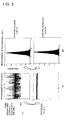
FIG. 2 is a graph showing one exemplary flow rate graph. -
FIGs. 3a and 3b are graphs showing one exemplary specified area range of the flow rate graph data. -
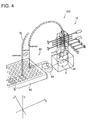
FIG. 4 is a perspective view of a preferred embodiment of a specimen discriminating and dispensing apparatus of the invention using the optical measuring apparatus. -
- 10
- Optical Measuring Apparatus
- 11a, 11b
- Measuring Section
- 12
- Flow Rate Calculating Section
- 13
- Flow Rate Graph Generating Section
- 14
- Flow Condition Judging Section
- 15
- Display Section
- 70
- Nozzle
- 80
- Dispensing Section
- 300
- Area Specifying Section
- 1000
- Specimen Discriminating and Dispensing Apparatus
- S
- Specimen (Sample)
- W
- Well
- One embodiment of the invention will be explained below with reference to the drawings. It is noted that the embodiment described below is described for the purpose of only explanation and does not limit a scope of the invention by any means. Accordingly, although a person skilled in the art may adopt an embodiment by replacing each or all components of the embodiment of the invention with same or corresponding components, such embodiment shall be also included within the scope of the invention.
-
FIG. 1 is a perspective view of a preferred embodiment of an optical measuring apparatus of the invention. - As shown in
FIG. 1 , the optical measuringapparatus 10 has two measuringsections rate calculating section 12 for calculating flow rates of the specimens, a flow rategraph generating section 13 for generating flow rate graph data and a flowcondition judging section 14 for judging flow conditions.
A plurality of specimens S and SR will be referred to also as micro-objects to be detected or as samples and are dispersed within asample fluid 30 in the present embodiment. A flow of thesample fluid 30 will be referred to as asample fluid 50 and flows ofsheath fluid 31 that surround thesample flow 50 will be referred to as sheath flows 55. Here, the specimens S are assumed to be object specimens to be dispensed and the specimens SR to be non-object specimens to be disposed here. - The measuring
section 11a is provided with a laser (light source) 113a, an irradiatingoptical fiber 112a, a transmittedlight receiving fiber 111a and a light receiving element (PD) 114a. The measuringsection 11b is also provided with alaser 113b, an irradiatingoptical fiber 112b, a transmittedlight receiving fiber 111b and a light receiving element (PD) 114b. - The measuring
section 11a irradiates exciting light irradiated from the laser 113a to the specimens S and SR passing through thesample flow 50 through the irradiationoptical fiber 112a and receives transmitted light by thePD 114a through thelight receiving fiber 111a that receives the transmitted light. Then, the measuringsection 11a transmits data on measured time when the light is received by thePD 114a to the flowrate calculating section 12.
In the same manner with the measuringsection 11a, the measuringsection 11b distant from the measuringsection 11a by a predetermined distance H in a flow passage direction (Z-direction) also receives transmitted light irradiated to the specimens S and SR passing through thesample flow 50 and transmits data on measured time when the light is received to the flowrate calculating section 12.
Accordingly, two measured time data measured at the measuringsections rate calculating section 12. It is noted that although the predetermined distance H is not specifically limited, it is about 750 µm which is equal to a size of diameters of three optical fibers in the embodiment ofFIG. 1 . - A
regulator 42 controls and regulates pressure of thesample flow 50 and apressure sensor 44 measures the pressure. The pressure measured by thepressure sensor 44 is used as a measurement parameter to judge the flow condition or is used for feedback control of the pressure of thesample flow 50. - A
regulator 41 also controls and regulates pressure of thesheath flow 55 and apressure sensor 43 measures the pressure. The pressure measured by thepressure sensor 43 is used as a measurement parameter to judge the flow condition or is used for feedback control of the pressure of thesheath flow 55. - The measuring
section 11a inFIG. 1 also receives fluorescent data of the specimens S and SR through a side light receiving fiber 26 and side scattered light data through a photomultiplier (PMT) 25. Still more, the measuringsection 11b receives fluorescent data of the specimens S and SR through a side light receiving fiber 27 and side scattered light data through aphotomultipliers PMTs - The flow
rate calculating section 12 inFIG. 1 calculates values of flow rate of the specimens S and SR based on the two measured time data measured by the measuringsections sections - The flow rate
graph generating section 13 inFIG. 1 generates flow rate graph data in which the values of flow rate of the specimens S and SR calculated by the flowrate calculating section 12 are arrayed in order of calculated time and outputs the generated flow rate graph data to the displaying section 15 to display the flow rate graph.
FIG. 2 shows one exemplary flow rate graph.FIG. 2 denotes the flow rate along an axis of ordinate and the specimens S and SR sequentially along an axis of abscissas. The displaying section 15 displaysFIG. 2 so that users can perceive the flow rate conditions of the specimens S and SR within thesample flow 50. - The flow rate
graph generating section 13 also has anarea specifying section 300 that allows the users to specify a desired graph area range within the flow rate graph displayed on the displaying section 15 through an input section not shown and that acquires the values of flow rate within the specified graph area range. Then, the flow rategraph generating section 13 generates flow rate graph data in which the values of flow rate of the specified area range are arrayed again in order of calculated time and outputs the generated flow rate graph data to the displaying section 15 to display the flow rate graph. -
FIGs. 3a and 3b are graphs showing one exemplary specified area range of the flow rate graph data, whereinFIG. 3a shows a measurement result of the flow rate andFIG. 3b shows a measurement result of fluorescent light. As shown inFIG. 3a , as a result of specifying agraph area range 400 within the flow rate graph shown inFIG. 2 , the specimens within the specified range present a flow rate graph in which the values of flow rate are stable. That is, a coefficient of variation Cv of the flow rate drops from 6.7 % to 0.9 %. Still more, a coefficient of variation Cv of frequency of peaks of the fluorescent data measured from the specimens within the specified range drops from 38.2 % to 34.0 %. Thus, the variations drop as a result. - The flow
condition judging section 14 inFIG. 1 judges the flow condition by analyzing the various parameters such as the flow rate graph data generated by the flow rategraph generating section 13 and the measured parameters such as the values of flow rate calculated by the flowrate calculating section 12, the pressure of thesample flow 50 and thesheath flow 55 measured by thepressure sensors - Thus, the optical measuring
apparatus 10 of the embodiment of the invention described above allows the users to perceive the actual flow condition by calculating the flow rates of the specimens S and SR and by setting the calculated flow rates as the measurement parameters. For instance, the optical measuringapparatus 10 allows the users to perceive the flow condition by displaying the flow rate of each specimen as the graph in a time-series manner with respect to the measured time and the other measurement parameters on the display. When an abnormality occurs, the optical measuringapparatus 10 also allows the users to perceive the abnormality by displaying the abnormal state on the display and by outputting a sound and permits to shorten a time for recovering to a normal state. - Next, one exemplary specimen discriminating and dispensing apparatus using the optical measuring
apparatus 10 will be explained.FIG. 4 is a perspective view of a preferred embodiment of the specimen discriminating and dispensing apparatus of the invention using the optical measuringapparatus 10. - As shown in
FIG. 4 , the specimen discriminating and dispensingapparatus 1000 has the optical measuringapparatus 10 and aspecimen dispensing section 80. As described above, the optical measuringapparatus 10 discriminates the specimens S and SR by measuring the optical data of the specimens S and SR and judges the flow condition by calculating the values of flow rate of the specimens S and SR. - The dispensing
section 80 injects the plurality of specimens S discriminated by the optical measuringapparatus 10 to wells (one exemplary container) W located at an arbitrary dispensing object region of a culture plate (referred to simply as a plate hereinafter) through anozzle 70 or disposes the specimens SR to be disposed to awaste fluid tank 84 through thenozzle 70. Here, theplate 200 has a plurality of wells W which are arrayed in matrix with a certain pitch along X-axis and Y-axis directions. A distance of the pitch depends on a shape of a tip of thenozzle 70 and may be what prevents the sample fluid overflowing from the well W from entering the neighboring well W. That is, the pitch distance may be narrow if the well W is deep and if the well W is shallow, the pitch distance is widened as much as possible. It is noted that the tip of thenozzle 70 can be readily inserted into the well W if a diameter of the well W is about two times of an outer diameter of the tip of thenozzle 70. - The specimen discriminating and dispensing
apparatus 1000 executes the dispensing process by calculating a time (arrival time) when the specimens S and SR arrive to the tip of thenozzle 70 based on the values of flow rate calculated by the optical measuringapparatus 10 and by controlling the operations of the dispensingsection 80 and thenozzle 70 based on the calculated arrival time. - Thereby, the specimen discriminating and dispensing
apparatus 1000 can measure the invariable optical data and can execute the dispensing operation accurately by stabilizing the flow rates by allowing the users to perceive the flow condition. - Still more, it is possible to measure invariable optical data by dispensing the specimens S and SR which are selected by the
area specifying section 300 of the optical measuringapparatus 10 and whose flow rates are stable and by measuring the optical data by the optical measuringapparatus 10 again. Thus, it becomes possible to execute the dispensing operation accurately and efficiently. - By the way, the present invention is not limited to the embodiment described above and may be modified variously.
- For instance, it becomes possible to let the users to perceive an abnormality quickly by adding a sound output section, a lamp and others to the apparatus shown in
FIG. 1 when the abnormality is found in the flow condition. Still more, it becomes possible to let the users to execute operations for recovering from the abnormal state. - Furthermore, it is possible to avoid a serious abnormality from occurring by allowing the users to perceive the flow condition.
- Although the
dispensing section 80 is the plate in the embodiment described above, it is not limited to be a plate and may be a tube, dish and the like. - The exciting light of the invention may be also referred to as a measuring light or an irradiation light.
- The optical measuring apparatus of the invention is applicable to all kinds of fields requiring inspection, observation and analysis related to biological polymers such as genes, immune systems, proteins, amino acids and sugar groups, e.g., to fields of engineering, agriculture in general such as food, agriculture and seafood processing, pharmacy, medicines such as sanitary, health, immune, diseases and genetics and sciences such as chemistry and biology.
Claims (10)
- An optical measuring apparatus for measuring optical data of specimens, i.e., objects to be measured, dispersed in a sample fluid flowing within a flow passage by irradiating light to said specimens, comprising:a plurality of measuring sections each having a light irradiating section for irradiating light to said specimens and a light receiving section for receiving the optical data acquired by irradiating the_light to said specimens; anda flow rate calculating section for calculating values of flow rate of said specimens based on a difference of measured times of said optical data measured by said plurality of measuring sections with respect to said specimens and a distance between said plurality of measuring sections.
- The optical measuring apparatus according to Claim 1, characterized in that the values of flow rate of said specimens calculated by said flow rate calculating section are adopted as measurement parameters for judging flow conditions of said sample fluid.
- The optical measuring apparatus according to Claim 1 or 2, characterized in that said optical measuring apparatus further comprising a flow rate graph generating section for generating flow rate graph data in which the values of flow rate of said specimens calculated by said flow rate calculating section are arrayed in order of calculation in a time-series manner and outputting said generated flow rate graph data to a display section.
- The optical measuring apparatus according to Claim 2 or 3, characterized in that said optical measuring apparatus further comprising a flow condition judging section for judging the flow condition of said specimens within said flow passage based on said measurement parameters including the values of flow rate of said specimens and outputting the judged resultant data to an output section including said display section.
- The optical measuring apparatus according to Claim 3, characterized in that said flow rate graph generating section comprises an area range specifying section for specifying a desired graph area range within said entire flow rate graph data and acquiring the values of flow rate of said specimens within said specified graph area range;
generates flow rate graph data in which the values of flow rate of said specimens acquired by said area specifying section are arrayed in a time-series manner in order calculated by said flow rate calculating section; and
outputs said generated flow rate graph data to said display section. - A specimen discriminating and dispensing apparatus for sorting object specimens, i.e., objects to be sorted, among specimens, i.e., objects to be measured, dispersed in a sample fluid flowing through a flow passage, comprising:the optical measuring apparatus described in any one of Claims 1 through 5; anda dispensing section for dispensing said specimens discriminated based on said measurement parameters measured by said optical measuring apparatus to dispensing object regions through a nozzle.
- The optical measuring apparatus according to Claim 6, characterized in that said specimen discriminating and dispensing apparatus sorts said specimens corresponding to said flow rate graph data within said graph area range specified by said area specifying section of said optical measuring apparatus as said object specimens.
- The optical measuring apparatus according to Claim 6 or 7, characterized in that said specimen discriminating and dispensing apparatus dispenses the object specimens from a tip of said nozzle to said dispensing object region even if the flow rate of said measured object specimen varies in sorting said specimens corresponding to said flow rate graph data within said graph area range specified by said area specifying section of said optical measuring apparatus by calculating a time for dispensing the object specimen based on a relationship related to the measured flow rate of the object specimen.
- The optical measuring apparatus according to Claim 8, characterized in that said specimen discriminating and dispensing apparatus dispenses one or a plurality of measured objects to said dispensing object regions after going through a flow rate slower than a flow rate at position where the specimen, i.e., the object to be measured, is measured.
- The optical measuring apparatus according to Claim 9, characterized in that said specimen discriminating and dispensing apparatus dispenses said object to be measured, i.e., the specimen, to said dispensing object region by switching a positional relationship between the tip of the nozzle of the pipe line and said dispensing object region by a time for dispensing said object to be measured calculated based on the measured and calculated flow rate.
Applications Claiming Priority (1)
| Application Number | Priority Date | Filing Date | Title |
|---|---|---|---|
| PCT/JP2009/050014 WO2010079586A1 (en) | 2009-01-06 | 2009-01-06 | Optical measurement apparatus and sample identifying and dispensing apparatus |
Publications (3)
| Publication Number | Publication Date |
|---|---|
| EP2383551A1 true EP2383551A1 (en) | 2011-11-02 |
| EP2383551A4 EP2383551A4 (en) | 2017-11-08 |
| EP2383551B1 EP2383551B1 (en) | 2020-04-08 |
Family
ID=42316364
Family Applications (1)
| Application Number | Title | Priority Date | Filing Date |
|---|---|---|---|
| EP09837475.4A Not-in-force EP2383551B1 (en) | 2009-01-06 | 2009-01-06 | Optical measurement apparatus and sample identifying and dispensing apparatus |
Country Status (4)
| Country | Link |
|---|---|
| US (1) | US9541489B2 (en) |
| EP (1) | EP2383551B1 (en) |
| CN (1) | CN102272561B (en) |
| WO (1) | WO2010079586A1 (en) |
Families Citing this family (7)
| Publication number | Priority date | Publication date | Assignee | Title |
|---|---|---|---|---|
| WO2014038640A1 (en) * | 2012-09-06 | 2014-03-13 | 古河電気工業株式会社 | Device for identifying and dispensing samples and method for identifying and dispensing samples |
| CN104535481B (en) * | 2014-12-29 | 2017-04-05 | 中国科学院长春光学精密机械与物理研究所 | imaging flow cytometer |
| JP6319193B2 (en) * | 2015-06-03 | 2018-05-09 | 東京エレクトロン株式会社 | Substrate processing apparatus and substrate processing method |
| CN105424572A (en) * | 2015-12-23 | 2016-03-23 | 电子科技大学 | On-line detector for particle impurities in transformer oil |
| US10324203B2 (en) * | 2016-12-14 | 2019-06-18 | Pgs Geophysical As | Cross-line source separation based on cross-line streamer separation |
| TWI773721B (en) * | 2017-01-20 | 2022-08-11 | 日商東京威力科創股份有限公司 | Foreign body detection device, foreign body detection method, and memory medium |
| CN115867811B (en) * | 2020-09-24 | 2026-06-30 | 株式会社日立高新技术 | Automatic analysis device |
Family Cites Families (17)
| Publication number | Priority date | Publication date | Assignee | Title |
|---|---|---|---|---|
| JPS56154667A (en) | 1980-05-01 | 1981-11-30 | Olympus Optical Co Ltd | Partial injection |
| US5170438A (en) * | 1991-03-22 | 1992-12-08 | Graham Fiber Glass Limited | Method and apparatus for determining the flow rate of a viscous fluid stream |
| JPH08178824A (en) * | 1994-12-21 | 1996-07-12 | Toa Medical Electronics Co Ltd | Particle measuring device |
| JP2000205905A (en) | 1999-01-08 | 2000-07-28 | Yazaki Corp | Evaluation method of fluid vibration type flow meter |
| US6192813B1 (en) * | 1999-05-21 | 2001-02-27 | Flexi-Coil Ltd. | Apparatus for controlling the flow rate of an air seeder |
| US7261002B1 (en) * | 1999-07-02 | 2007-08-28 | Cidra Corporation | Flow rate measurement for industrial sensing applications using unsteady pressures |
| JP4209565B2 (en) | 1999-10-01 | 2009-01-14 | アロカ株式会社 | Automatic dispensing device |
| US20040067167A1 (en) * | 2002-10-08 | 2004-04-08 | Genoptix, Inc. | Methods and apparatus for optophoretic diagnosis of cells and particles |
| CA2449551A1 (en) * | 2003-11-17 | 2005-05-17 | Photon Control Inc. | Optical device and method for sensing multiphase flow |
| CN102519919B (en) * | 2004-04-23 | 2016-03-16 | 古河电气工业株式会社 | The separation of sample, identification, dispensing method and its device and resolver |
| JP2007064759A (en) | 2005-08-30 | 2007-03-15 | Hoyutec Kk | Fluid transfer device |
| JP4089916B2 (en) * | 2005-09-30 | 2008-05-28 | 国立大学法人富山大学 | Simultaneous measurement of multicellular responses |
| JP2007121179A (en) * | 2005-10-31 | 2007-05-17 | Shimadzu Corp | Analysis graph display device |
| JP2008116381A (en) * | 2006-11-07 | 2008-05-22 | Tokyo Univ Of Agriculture & Technology | Micro pump |
| JP5074833B2 (en) * | 2007-06-19 | 2012-11-14 | 古河電気工業株式会社 | Optical measuring device and specimen identification and dispensing device |
| US8211708B2 (en) | 2009-03-13 | 2012-07-03 | Furukawa Electric Co., Ltd. | Optical measuring device and method therefor |
| US7957002B2 (en) | 2009-03-13 | 2011-06-07 | The Furukawa Electric Co., Ltd. | Method for optical measurement and optical measurement apparatus |
-
2009
- 2009-01-06 WO PCT/JP2009/050014 patent/WO2010079586A1/en not_active Ceased
- 2009-01-06 CN CN200980153167.9A patent/CN102272561B/en not_active Expired - Fee Related
- 2009-01-06 EP EP09837475.4A patent/EP2383551B1/en not_active Not-in-force
-
2011
- 2011-07-06 US US13/176,781 patent/US9541489B2/en not_active Expired - Fee Related
Non-Patent Citations (1)
| Title |
|---|
| See references of WO2010079586A1 * |
Also Published As
| Publication number | Publication date |
|---|---|
| WO2010079586A1 (en) | 2010-07-15 |
| EP2383551B1 (en) | 2020-04-08 |
| US9541489B2 (en) | 2017-01-10 |
| US20120004864A1 (en) | 2012-01-05 |
| EP2383551A4 (en) | 2017-11-08 |
| CN102272561B (en) | 2014-05-14 |
| CN102272561A (en) | 2011-12-07 |
Similar Documents
| Publication | Publication Date | Title |
|---|---|---|
| US9541489B2 (en) | Optical measuring apparatus and specimen discriminating and dispensing apparatus | |
| EP2724144B1 (en) | Characterization of motion-related error in a stream of moving micro-entities | |
| CN102519919B (en) | The separation of sample, identification, dispensing method and its device and resolver | |
| JP7152414B2 (en) | Method and apparatus for bulk sorting of microparticles using microfluidic channels | |
| US20200150023A1 (en) | Instrument and Method for Optical Particle Sensing | |
| US6372506B1 (en) | Apparatus and method for verifying drop delay in a flow cytometer | |
| CN114127537B (en) | System and method for sample-to-sample separation of gas detection | |
| EP2347243B1 (en) | Optical flow cytometer and method of analysis | |
| US9435728B2 (en) | Sample identification/sorting apparatus and sample identification/sorting method | |
| JP5304434B2 (en) | Fine particle measuring device | |
| EP3204756B1 (en) | Particle analysis and sorting apparatus | |
| EP2378283A1 (en) | Flow path device, complex dielectric constant measurement device, and dielectric cytometry device | |
| US20160231223A1 (en) | Fluidic chip for flow cytometry and methods of use | |
| CN114641450B (en) | Microfluidic devices and methods for sampling and analyzing cells using optical and Raman spectroscopy. | |
| JP5260949B2 (en) | Optical measuring device and optical measuring method | |
| CN102272574A (en) | Optical information analysis device and optical information analysis method | |
| US10823657B2 (en) | Flow cell for analyzing particles in a liquid to be examined | |
| US20050169802A1 (en) | Apparatus for pumping and directing fluids for hematology testing | |
| JP4540506B2 (en) | Method and apparatus for controlling position of sample liquid flow | |
| JP5074833B2 (en) | Optical measuring device and specimen identification and dispensing device | |
| US20190257736A1 (en) | System and Method for Precision Deposition of Liquid Droplets | |
| US11686662B2 (en) | Microparticle sorting device and method for sorting microparticles | |
| CN105021572B (en) | Urine sample analysis method and urine sample analytical equipment | |
| US12485420B2 (en) | Systems and methods for multi-junction particle sorting in injection-molded articles | |
| Taylor | The design and evaluation of a microfluidic cell sorting chip |
Legal Events
| Date | Code | Title | Description |
|---|---|---|---|
| PUAI | Public reference made under article 153(3) epc to a published international application that has entered the european phase |
Free format text: ORIGINAL CODE: 0009012 |
|
| 17P | Request for examination filed |
Effective date: 20110728 |
|
| AK | Designated contracting states |
Kind code of ref document: A1 Designated state(s): AT BE BG CH CY CZ DE DK EE ES FI FR GB GR HR HU IE IS IT LI LT LU LV MC MK MT NL NO PL PT RO SE SI SK TR |
|
| DAX | Request for extension of the european patent (deleted) | ||
| RIC1 | Information provided on ipc code assigned before grant |
Ipc: G01N 21/64 20060101ALI20120625BHEP Ipc: G01F 1/708 20060101AFI20120625BHEP Ipc: G01N 21/49 20060101ALI20120625BHEP Ipc: G01N 35/10 20060101ALI20120625BHEP |
|
| RA4 | Supplementary search report drawn up and despatched (corrected) |
Effective date: 20171006 |
|
| RIC1 | Information provided on ipc code assigned before grant |
Ipc: G01N 21/49 20060101ALI20170929BHEP Ipc: G01N 21/64 20060101ALI20170929BHEP Ipc: G01F 1/708 20060101AFI20170929BHEP Ipc: B07C 5/344 20060101ALI20170929BHEP Ipc: G01N 35/10 20060101ALI20170929BHEP |
|
| STAA | Information on the status of an ep patent application or granted ep patent |
Free format text: STATUS: REQUEST FOR EXAMINATION WAS MADE |
|
| GRAP | Despatch of communication of intention to grant a patent |
Free format text: ORIGINAL CODE: EPIDOSNIGR1 |
|
| STAA | Information on the status of an ep patent application or granted ep patent |
Free format text: STATUS: GRANT OF PATENT IS INTENDED |
|
| RIC1 | Information provided on ipc code assigned before grant |
Ipc: G01N 21/49 20060101ALI20190930BHEP Ipc: G01F 1/708 20060101AFI20190930BHEP Ipc: G01N 35/10 20060101ALI20190930BHEP Ipc: G01N 21/64 20060101ALI20190930BHEP Ipc: B07C 5/344 20060101ALI20190930BHEP |
|
| INTG | Intention to grant announced |
Effective date: 20191029 |
|
| GRAS | Grant fee paid |
Free format text: ORIGINAL CODE: EPIDOSNIGR3 |
|
| GRAA | (expected) grant |
Free format text: ORIGINAL CODE: 0009210 |
|
| STAA | Information on the status of an ep patent application or granted ep patent |
Free format text: STATUS: THE PATENT HAS BEEN GRANTED |
|
| AK | Designated contracting states |
Kind code of ref document: B1 Designated state(s): AT BE BG CH CY CZ DE DK EE ES FI FR GB GR HR HU IE IS IT LI LT LU LV MC MK MT NL NO PL PT RO SE SI SK TR |
|
| REG | Reference to a national code |
Ref country code: GB Ref legal event code: FG4D |
|
| REG | Reference to a national code |
Ref country code: AT Ref legal event code: REF Ref document number: 1255010 Country of ref document: AT Kind code of ref document: T Effective date: 20200415 Ref country code: CH Ref legal event code: EP |
|
| REG | Reference to a national code |
Ref country code: DE Ref legal event code: R096 Ref document number: 602009061699 Country of ref document: DE |
|
| REG | Reference to a national code |
Ref country code: IE Ref legal event code: FG4D |
|
| REG | Reference to a national code |
Ref country code: NL Ref legal event code: MP Effective date: 20200408 |
|
| REG | Reference to a national code |
Ref country code: LT Ref legal event code: MG4D |
|
| PG25 | Lapsed in a contracting state [announced via postgrant information from national office to epo] |
Ref country code: NL Free format text: LAPSE BECAUSE OF FAILURE TO SUBMIT A TRANSLATION OF THE DESCRIPTION OR TO PAY THE FEE WITHIN THE PRESCRIBED TIME-LIMIT Effective date: 20200408 Ref country code: LT Free format text: LAPSE BECAUSE OF FAILURE TO SUBMIT A TRANSLATION OF THE DESCRIPTION OR TO PAY THE FEE WITHIN THE PRESCRIBED TIME-LIMIT Effective date: 20200408 Ref country code: GR Free format text: LAPSE BECAUSE OF FAILURE TO SUBMIT A TRANSLATION OF THE DESCRIPTION OR TO PAY THE FEE WITHIN THE PRESCRIBED TIME-LIMIT Effective date: 20200709 Ref country code: IS Free format text: LAPSE BECAUSE OF FAILURE TO SUBMIT A TRANSLATION OF THE DESCRIPTION OR TO PAY THE FEE WITHIN THE PRESCRIBED TIME-LIMIT Effective date: 20200808 Ref country code: PT Free format text: LAPSE BECAUSE OF FAILURE TO SUBMIT A TRANSLATION OF THE DESCRIPTION OR TO PAY THE FEE WITHIN THE PRESCRIBED TIME-LIMIT Effective date: 20200817 Ref country code: FI Free format text: LAPSE BECAUSE OF FAILURE TO SUBMIT A TRANSLATION OF THE DESCRIPTION OR TO PAY THE FEE WITHIN THE PRESCRIBED TIME-LIMIT Effective date: 20200408 Ref country code: NO Free format text: LAPSE BECAUSE OF FAILURE TO SUBMIT A TRANSLATION OF THE DESCRIPTION OR TO PAY THE FEE WITHIN THE PRESCRIBED TIME-LIMIT Effective date: 20200708 Ref country code: SE Free format text: LAPSE BECAUSE OF FAILURE TO SUBMIT A TRANSLATION OF THE DESCRIPTION OR TO PAY THE FEE WITHIN THE PRESCRIBED TIME-LIMIT Effective date: 20200408 |
|
| REG | Reference to a national code |
Ref country code: AT Ref legal event code: MK05 Ref document number: 1255010 Country of ref document: AT Kind code of ref document: T Effective date: 20200408 |
|
| PG25 | Lapsed in a contracting state [announced via postgrant information from national office to epo] |
Ref country code: BG Free format text: LAPSE BECAUSE OF FAILURE TO SUBMIT A TRANSLATION OF THE DESCRIPTION OR TO PAY THE FEE WITHIN THE PRESCRIBED TIME-LIMIT Effective date: 20200708 Ref country code: LV Free format text: LAPSE BECAUSE OF FAILURE TO SUBMIT A TRANSLATION OF THE DESCRIPTION OR TO PAY THE FEE WITHIN THE PRESCRIBED TIME-LIMIT Effective date: 20200408 Ref country code: HR Free format text: LAPSE BECAUSE OF FAILURE TO SUBMIT A TRANSLATION OF THE DESCRIPTION OR TO PAY THE FEE WITHIN THE PRESCRIBED TIME-LIMIT Effective date: 20200408 |
|
| REG | Reference to a national code |
Ref country code: DE Ref legal event code: R097 Ref document number: 602009061699 Country of ref document: DE |
|
| PG25 | Lapsed in a contracting state [announced via postgrant information from national office to epo] |
Ref country code: CZ Free format text: LAPSE BECAUSE OF FAILURE TO SUBMIT A TRANSLATION OF THE DESCRIPTION OR TO PAY THE FEE WITHIN THE PRESCRIBED TIME-LIMIT Effective date: 20200408 Ref country code: ES Free format text: LAPSE BECAUSE OF FAILURE TO SUBMIT A TRANSLATION OF THE DESCRIPTION OR TO PAY THE FEE WITHIN THE PRESCRIBED TIME-LIMIT Effective date: 20200408 Ref country code: AT Free format text: LAPSE BECAUSE OF FAILURE TO SUBMIT A TRANSLATION OF THE DESCRIPTION OR TO PAY THE FEE WITHIN THE PRESCRIBED TIME-LIMIT Effective date: 20200408 Ref country code: DK Free format text: LAPSE BECAUSE OF FAILURE TO SUBMIT A TRANSLATION OF THE DESCRIPTION OR TO PAY THE FEE WITHIN THE PRESCRIBED TIME-LIMIT Effective date: 20200408 Ref country code: EE Free format text: LAPSE BECAUSE OF FAILURE TO SUBMIT A TRANSLATION OF THE DESCRIPTION OR TO PAY THE FEE WITHIN THE PRESCRIBED TIME-LIMIT Effective date: 20200408 Ref country code: RO Free format text: LAPSE BECAUSE OF FAILURE TO SUBMIT A TRANSLATION OF THE DESCRIPTION OR TO PAY THE FEE WITHIN THE PRESCRIBED TIME-LIMIT Effective date: 20200408 Ref country code: IT Free format text: LAPSE BECAUSE OF FAILURE TO SUBMIT A TRANSLATION OF THE DESCRIPTION OR TO PAY THE FEE WITHIN THE PRESCRIBED TIME-LIMIT Effective date: 20200408 |
|
| PLBE | No opposition filed within time limit |
Free format text: ORIGINAL CODE: 0009261 |
|
| STAA | Information on the status of an ep patent application or granted ep patent |
Free format text: STATUS: NO OPPOSITION FILED WITHIN TIME LIMIT |
|
| PG25 | Lapsed in a contracting state [announced via postgrant information from national office to epo] |
Ref country code: PL Free format text: LAPSE BECAUSE OF FAILURE TO SUBMIT A TRANSLATION OF THE DESCRIPTION OR TO PAY THE FEE WITHIN THE PRESCRIBED TIME-LIMIT Effective date: 20200408 Ref country code: SK Free format text: LAPSE BECAUSE OF FAILURE TO SUBMIT A TRANSLATION OF THE DESCRIPTION OR TO PAY THE FEE WITHIN THE PRESCRIBED TIME-LIMIT Effective date: 20200408 |
|
| 26N | No opposition filed |
Effective date: 20210112 |
|
| PG25 | Lapsed in a contracting state [announced via postgrant information from national office to epo] |
Ref country code: SI Free format text: LAPSE BECAUSE OF FAILURE TO SUBMIT A TRANSLATION OF THE DESCRIPTION OR TO PAY THE FEE WITHIN THE PRESCRIBED TIME-LIMIT Effective date: 20200408 |
|
| PG25 | Lapsed in a contracting state [announced via postgrant information from national office to epo] |
Ref country code: MC Free format text: LAPSE BECAUSE OF FAILURE TO SUBMIT A TRANSLATION OF THE DESCRIPTION OR TO PAY THE FEE WITHIN THE PRESCRIBED TIME-LIMIT Effective date: 20200408 |
|
| REG | Reference to a national code |
Ref country code: CH Ref legal event code: PL |
|
| PG25 | Lapsed in a contracting state [announced via postgrant information from national office to epo] |
Ref country code: LU Free format text: LAPSE BECAUSE OF NON-PAYMENT OF DUE FEES Effective date: 20210106 |
|
| REG | Reference to a national code |
Ref country code: BE Ref legal event code: MM Effective date: 20210131 |
|
| PG25 | Lapsed in a contracting state [announced via postgrant information from national office to epo] |
Ref country code: FR Free format text: LAPSE BECAUSE OF NON-PAYMENT OF DUE FEES Effective date: 20210131 |
|
| PG25 | Lapsed in a contracting state [announced via postgrant information from national office to epo] |
Ref country code: CH Free format text: LAPSE BECAUSE OF NON-PAYMENT OF DUE FEES Effective date: 20210131 Ref country code: LI Free format text: LAPSE BECAUSE OF NON-PAYMENT OF DUE FEES Effective date: 20210131 |
|
| PG25 | Lapsed in a contracting state [announced via postgrant information from national office to epo] |
Ref country code: IE Free format text: LAPSE BECAUSE OF NON-PAYMENT OF DUE FEES Effective date: 20210106 |
|
| PG25 | Lapsed in a contracting state [announced via postgrant information from national office to epo] |
Ref country code: BE Free format text: LAPSE BECAUSE OF NON-PAYMENT OF DUE FEES Effective date: 20210131 |
|
| REG | Reference to a national code |
Ref country code: DE Ref legal event code: R081 Ref document number: 602009061699 Country of ref document: DE Owner name: YAMATO SCIENTIFIC CO., LTD., JP Free format text: FORMER OWNER: THE FURUKAWA ELECTRIC CO., LTD., TOKYO, JP |
|
| PG25 | Lapsed in a contracting state [announced via postgrant information from national office to epo] |
Ref country code: HU Free format text: LAPSE BECAUSE OF FAILURE TO SUBMIT A TRANSLATION OF THE DESCRIPTION OR TO PAY THE FEE WITHIN THE PRESCRIBED TIME-LIMIT; INVALID AB INITIO Effective date: 20090106 Ref country code: CY Free format text: LAPSE BECAUSE OF FAILURE TO SUBMIT A TRANSLATION OF THE DESCRIPTION OR TO PAY THE FEE WITHIN THE PRESCRIBED TIME-LIMIT Effective date: 20200408 |
|
| PGFP | Annual fee paid to national office [announced via postgrant information from national office to epo] |
Ref country code: GB Payment date: 20230119 Year of fee payment: 15 Ref country code: DE Payment date: 20230123 Year of fee payment: 15 |
|
| REG | Reference to a national code |
Ref country code: GB Ref legal event code: 732E Free format text: REGISTERED BETWEEN 20230518 AND 20230524 |
|
| PG25 | Lapsed in a contracting state [announced via postgrant information from national office to epo] |
Ref country code: MK Free format text: LAPSE BECAUSE OF FAILURE TO SUBMIT A TRANSLATION OF THE DESCRIPTION OR TO PAY THE FEE WITHIN THE PRESCRIBED TIME-LIMIT Effective date: 20200408 |
|
| PG25 | Lapsed in a contracting state [announced via postgrant information from national office to epo] |
Ref country code: TR Free format text: LAPSE BECAUSE OF FAILURE TO SUBMIT A TRANSLATION OF THE DESCRIPTION OR TO PAY THE FEE WITHIN THE PRESCRIBED TIME-LIMIT Effective date: 20200408 |
|
| REG | Reference to a national code |
Ref country code: DE Ref legal event code: R119 Ref document number: 602009061699 Country of ref document: DE |
|
| GBPC | Gb: european patent ceased through non-payment of renewal fee |
Effective date: 20240106 |
|
| PG25 | Lapsed in a contracting state [announced via postgrant information from national office to epo] |
Ref country code: MT Free format text: LAPSE BECAUSE OF FAILURE TO SUBMIT A TRANSLATION OF THE DESCRIPTION OR TO PAY THE FEE WITHIN THE PRESCRIBED TIME-LIMIT Effective date: 20200408 |
|
| PG25 | Lapsed in a contracting state [announced via postgrant information from national office to epo] |
Ref country code: DE Free format text: LAPSE BECAUSE OF NON-PAYMENT OF DUE FEES Effective date: 20240801 |
|
| PG25 | Lapsed in a contracting state [announced via postgrant information from national office to epo] |
Ref country code: GB Free format text: LAPSE BECAUSE OF NON-PAYMENT OF DUE FEES Effective date: 20240106 |
|
| PG25 | Lapsed in a contracting state [announced via postgrant information from national office to epo] |
Ref country code: GB Free format text: LAPSE BECAUSE OF NON-PAYMENT OF DUE FEES Effective date: 20240106 Ref country code: DE Free format text: LAPSE BECAUSE OF NON-PAYMENT OF DUE FEES Effective date: 20240801 |