EP2383492A1 - Method for shifting a dual clutch transmission - Google Patents
Method for shifting a dual clutch transmission Download PDFInfo
- Publication number
- EP2383492A1 EP2383492A1 EP11162692A EP11162692A EP2383492A1 EP 2383492 A1 EP2383492 A1 EP 2383492A1 EP 11162692 A EP11162692 A EP 11162692A EP 11162692 A EP11162692 A EP 11162692A EP 2383492 A1 EP2383492 A1 EP 2383492A1
- Authority
- EP
- European Patent Office
- Prior art keywords
- gear
- clutch
- source
- transmission
- started
- Prior art date
- Legal status (The legal status is an assumption and is not a legal conclusion. Google has not performed a legal analysis and makes no representation as to the accuracy of the status listed.)
- Granted
Links
Images


Classifications
-
- F—MECHANICAL ENGINEERING; LIGHTING; HEATING; WEAPONS; BLASTING
- F16—ENGINEERING ELEMENTS AND UNITS; GENERAL MEASURES FOR PRODUCING AND MAINTAINING EFFECTIVE FUNCTIONING OF MACHINES OR INSTALLATIONS; THERMAL INSULATION IN GENERAL
- F16H—GEARING
- F16H61/00—Control functions within control units of change-speed- or reversing-gearings for conveying rotary motion ; Control of exclusively fluid gearing, friction gearing, gearings with endless flexible members or other particular types of gearing
- F16H61/68—Control functions within control units of change-speed- or reversing-gearings for conveying rotary motion ; Control of exclusively fluid gearing, friction gearing, gearings with endless flexible members or other particular types of gearing specially adapted for stepped gearings
- F16H61/684—Control functions within control units of change-speed- or reversing-gearings for conveying rotary motion ; Control of exclusively fluid gearing, friction gearing, gearings with endless flexible members or other particular types of gearing specially adapted for stepped gearings without interruption of drive
- F16H61/688—Control functions within control units of change-speed- or reversing-gearings for conveying rotary motion ; Control of exclusively fluid gearing, friction gearing, gearings with endless flexible members or other particular types of gearing specially adapted for stepped gearings without interruption of drive with two inputs, e.g. selection of one of two torque-flow paths by clutches
-
- B—PERFORMING OPERATIONS; TRANSPORTING
- B60—VEHICLES IN GENERAL
- B60Y—INDEXING SCHEME RELATING TO ASPECTS CROSS-CUTTING VEHICLE TECHNOLOGY
- B60Y2300/00—Purposes or special features of road vehicle drive control systems
- B60Y2300/18—Propelling the vehicle
- B60Y2300/18008—Propelling the vehicle related to particular drive situations
- B60Y2300/18066—Coasting
- B60Y2300/18083—Coasting without torque flow between driveshaft and engine, e.g. with clutch disengaged or transmission in neutral
-
- F—MECHANICAL ENGINEERING; LIGHTING; HEATING; WEAPONS; BLASTING
- F16—ENGINEERING ELEMENTS AND UNITS; GENERAL MEASURES FOR PRODUCING AND MAINTAINING EFFECTIVE FUNCTIONING OF MACHINES OR INSTALLATIONS; THERMAL INSULATION IN GENERAL
- F16H—GEARING
- F16H61/00—Control functions within control units of change-speed- or reversing-gearings for conveying rotary motion ; Control of exclusively fluid gearing, friction gearing, gearings with endless flexible members or other particular types of gearing
- F16H61/04—Smoothing ratio shift
- F16H2061/0425—Bridging torque interruption
-
- F—MECHANICAL ENGINEERING; LIGHTING; HEATING; WEAPONS; BLASTING
- F16—ENGINEERING ELEMENTS AND UNITS; GENERAL MEASURES FOR PRODUCING AND MAINTAINING EFFECTIVE FUNCTIONING OF MACHINES OR INSTALLATIONS; THERMAL INSULATION IN GENERAL
- F16H—GEARING
- F16H61/00—Control functions within control units of change-speed- or reversing-gearings for conveying rotary motion ; Control of exclusively fluid gearing, friction gearing, gearings with endless flexible members or other particular types of gearing
- F16H61/04—Smoothing ratio shift
- F16H2061/0444—Smoothing ratio shift during fast shifting over two gearsteps, e.g. jumping from fourth to second gear
-
- F—MECHANICAL ENGINEERING; LIGHTING; HEATING; WEAPONS; BLASTING
- F16—ENGINEERING ELEMENTS AND UNITS; GENERAL MEASURES FOR PRODUCING AND MAINTAINING EFFECTIVE FUNCTIONING OF MACHINES OR INSTALLATIONS; THERMAL INSULATION IN GENERAL
- F16H—GEARING
- F16H2306/00—Shifting
- F16H2306/14—Skipping gear shift
-
- F—MECHANICAL ENGINEERING; LIGHTING; HEATING; WEAPONS; BLASTING
- F16—ENGINEERING ELEMENTS AND UNITS; GENERAL MEASURES FOR PRODUCING AND MAINTAINING EFFECTIVE FUNCTIONING OF MACHINES OR INSTALLATIONS; THERMAL INSULATION IN GENERAL
- F16H—GEARING
- F16H61/00—Control functions within control units of change-speed- or reversing-gearings for conveying rotary motion ; Control of exclusively fluid gearing, friction gearing, gearings with endless flexible members or other particular types of gearing
- F16H61/04—Smoothing ratio shift
- F16H61/08—Timing control
-
- Y—GENERAL TAGGING OF NEW TECHNOLOGICAL DEVELOPMENTS; GENERAL TAGGING OF CROSS-SECTIONAL TECHNOLOGIES SPANNING OVER SEVERAL SECTIONS OF THE IPC; TECHNICAL SUBJECTS COVERED BY FORMER USPC CROSS-REFERENCE ART COLLECTIONS [XRACs] AND DIGESTS
- Y10—TECHNICAL SUBJECTS COVERED BY FORMER USPC
- Y10T—TECHNICAL SUBJECTS COVERED BY FORMER US CLASSIFICATION
- Y10T74/00—Machine element or mechanism
- Y10T74/19—Gearing
- Y10T74/19219—Interchangeably locked
- Y10T74/19251—Control mechanism
-
- Y—GENERAL TAGGING OF NEW TECHNOLOGICAL DEVELOPMENTS; GENERAL TAGGING OF CROSS-SECTIONAL TECHNOLOGIES SPANNING OVER SEVERAL SECTIONS OF THE IPC; TECHNICAL SUBJECTS COVERED BY FORMER USPC CROSS-REFERENCE ART COLLECTIONS [XRACs] AND DIGESTS
- Y10—TECHNICAL SUBJECTS COVERED BY FORMER USPC
- Y10T—TECHNICAL SUBJECTS COVERED BY FORMER US CLASSIFICATION
- Y10T74/00—Machine element or mechanism
- Y10T74/19—Gearing
- Y10T74/19219—Interchangeably locked
- Y10T74/19284—Meshing assisters
- Y10T74/19288—Double clutch and interposed transmission
Definitions
- the invention relates to a method for switching a dual-clutch transmission.
- the DE 198 53 824 A1 discloses a dual-clutch transmission with a plurality of gears having first and second parallel power transmission branches.
- a first main clutch is associated with the first power transmission branch while a second main clutch is associated with the second power transmission branch.
- gear shift stages are arranged in a power transmission branch. To avoid a traction interruption during the shift between two gear stages, which are assigned to a power transmission branch, during the switching operation, power is transmitted at least briefly over the other power transmission branch.
- the DE 103 49 220 A1 relates to a method for switching a dual-clutch transmission of a motor vehicle.
- a switching operation in which is switched from a source gear in a target gear, wherein the source gear and the target gear are associated with a power transmission path, a support gear is at least temporarily inserted in the other power transmission path to avoid a traction interruption.
- the control of the shifting process in the transmission from the source gear to the target gear is performed such that the engine speed tapers in the direction of the synchronous rotational speed of the target gear with an almost constant gradient.
- the DE 101 51 260 A1 relates to a method for controlling a dual-clutch transmission. In order to achieve a sporty driving behavior, is deliberately dispensed with a double downshift to an uninterrupted power transmission during the gear stage change on another sub-transmission.
- the time required for shifting the dual-clutch transmission from a source gear to a target gear when the target gear and the output gear are associated with a common drive shaft may critically depend on the duration required for disengaging a gear associated with the source gear or the setting of a gear assigned to the target gear is required.
- a target gearwheel can only be set when the source gearwheel has already been released.
- This object is achieved by a method for switching a dual clutch transmission, in particular of a motor vehicle, wherein the dual clutch transmission has two drive shafts and a transmission output shaft, wherein the first drive shaft, a first clutch and the second drive shaft is associated with a second clutch and both clutches for transmitting different clutch torques completely or partially openable or closable, wherein the first drive shaft and the second drive shaft are each assigned certain different gear ratios, wherein at least partially a first power transmission path is formed by the first clutch and by the first drive shaft from the transmission input shaft to the transmission output shaft and wherein by the second clutch and at least partially formed by the second drive shaft, a second power transmission path from the transmission input shaft to the transmission output shaft, starting from a source gear to be switched to a target gear, which is switched at least briefly in a support gear before turning on the target gear when the target gear and the source gear are assigned to the same drive shaft.
- Engine torque can be via at least one power transmission path be transmitted from the transmission input shaft to the transmission output shaft.
- the invention is characterized in that, with an uninterrupted reduction of the transmitted clutch torque on the coupling associated with the source gear, the value zero has begun, before the closing of the clutch assigned to the support gear is started.
- the invention may also be characterized by features of other dependent claims.
- the invention relates to such a method for switching a dual-clutch transmission, in which is to be switched from a source gear in a target gear, in particular, the target gear and the output gear of the same drive shaft are assigned. At least in the short term will be switched to a support gear.
- the course of the engine speed is preferably always aligned during such a switching operation on the target gear, which may mean that the engine speed is accelerated or decelerated in a largely constant manner to the corresponding engine speed in the target gear. It is provided in particular that the engine speed does not remain at a corresponding speed level corresponding to the engine speed in the support gear. Rather, it is preferably provided that the curve of the actual engine speed cuts the curve of the notional engine speed with switched support gear only in one point.
- the phrase "engage a gear” is understood in particular to mean that a gear assigned to a specific gear is set on a shaft via a dog clutch or a similar device, and then a force flow can take place via this gear. It is irrelevant for the insertion, whether the gear to be engaged assigned clutch is closed or not, so that in fact a power flow can be made from a transmission input shaft to the transmission output shaft via the corresponding gear.
- the term "disengaging a gear” is understood in particular to mean that the respective gear assigned to the corresponding gear is released from a shaft, so that no force flow can take place via this gear.
- the gear to be interpreted associated clutch may be open during the disengagement of the gear, so that at the time of release of the gear from the shaft no power flow can be made from a transmission input shaft to the transmission output shaft via the corresponding gear.
- the phrase “shifting into gear” is understood to mean that the dual-clutch transmission is converted into a state of a specific speed ratio starting from a transmission input shaft to a transmission output shaft.
- the process of "switching to a gear” may include engaging or disengaging gears and opening and closing at least one of the two clutches, so that a power transmission path is established from the transmission input shaft to the transmission output shaft.
- closing a clutch is understood in particular to mean a process in which a defined buildup of torque transmission capacity takes place at the clutch, in particular for the purpose of transmitting power from a transmission input shaft to a transmission output shaft. In particular, closing can only take place after reaching the so-called “touch point”, in which there is no longer any play between the disks of a multi-disk clutch or a force-applying means and a disk.
- a possible clutch filling or prefilling, which is provided in particular for bridging or removing game, is not understood in the context of the present invention by "closing a clutch", even if a drag torque can be increased during the Kupplungsvorbe committees.
- a "reduction of a transmitting clutch torque to the value zero" is to be understood in particular as meaning that, when the value zero is reached, substantially no more drive torque can be transmitted via the corresponding clutch.
- Possible drag torques which may also be due to the fact that even when the clutch is fully open due to frictional or flow forces, a certain transfer of torque still occurs, can be neglected.
- the source gear associated clutch is closed, a gear assigned to the source gear can not be released from the corresponding shaft, since this can still be under load. Therefore, a reduction of the load is first necessary, which is achieved by the uninterrupted reduction of the transmitted clutch torque at the source gear associated clutch to the value zero.
- the coupling associated with the source gear is opened, preferably as quickly as possible.
- Under an uninterrupted reduction is to be understood in particular that the transmitted clutch torque on the clutch at any time has a rising course. It is possible that at least for a short time, a constant course is possible at a time. However, it is preferred that at no time a constant course is provided.
- the clutch torque curve is therefore preferably always sloping over time.
- the uninterrupted reduction has a largely linear course.
- This can result in a smooth opening of the clutch, which can have a positive effect on the driving behavior.
- Such courses are also included, in which at the beginning and end of the opening process transitions such as concave or convex curves are provided in the corresponding curve.
- the duration of the continuous reduction of the transmitted clutch torque is controlled as a function of the time required for the engagement and / or the clutch filling of the support gear.
- the duration of the uninterrupted reduction of the transmitted clutch torque is controlled as a function of the time required for laying out the source gear and setting the target gear.
- the closing of the clutch associated with the support gear is not started until the clutch assigned to the output gear is completely opened.
- a targeted interruption of traction can be understood by the driver as an expression of a sporty driving style, especially if this is understood as an immediate reaction to a driving command, such as kickdown.
- the support gear is inserted. Due to the temporal overlap of laying out the source gear or opening the clutch and inserting the support gear, a temporal optimization of the overall switching operation can also be achieved.
- the target gear associated clutch is closed.
- This process corresponds largely to the usual process used in the dual-clutch transmission of the change of power transmission from one drive shaft to the other drive shaft, so that largely a traction interruption can be avoided.
- a traction interruption is possible; at a later time of the switching process,
- a traction interruption of a driver is no longer perceived as pleasant, since this interruption of traction can then no longer be brought into direct relationship with the original driving command, eg kickdown.
- closing of the clutch associated with the support gear is initiated.
- Sailing is understood as meaning a state of the vehicle in which one or two gears are engaged, but both clutches assigned to the respective drive shafts are open. A coupling between the drive motor and wheels of the vehicle is then not available.
- the support gear associated clutch is closed, the shift can be shortened in total time. It may also be included in the period in which the engine speed is accelerated from an idle speed to a certain speed at which a support on the support gear without noticeable braking of the vehicle is possible.
- the invention further relates to a dual-clutch transmission, which is connected by means of a method according to one of the preceding claims.
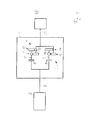
- FIG. 1 shows a dual-clutch transmission 1, which can be controlled by a method according to the invention for switching.
- the dual-clutch transmission 1 is drive-connected by means of a transmission input shaft 3 with a drive motor 2.
- the dual-clutch transmission 1 has a first partial transmission 4 with a first drive shaft 5, wherein the drive shaft 5 is drive-connected to the transmission input shaft 3 via a first clutch 8.
- a separation of the drive connection of the first drive shaft 5 can be made of the transmission input shaft 3.
- the first partial transmission 4 is connected to a common transmission output shaft 17, to which a differential gear 18 can be connected.
- the first drive shaft 5 and the first output shaft 15 is assigned a first wheel pair 11 and a third wheel pair 13.
- At least one gear wheel of the first or third pair of wheels can be connected or released to the drive shaft or the output shaft.
- the gear is defined, which is inserted in the respective partial transmission.
- the dual-clutch transmission 1 has a second partial transmission 6, which essentially corresponds to the first partial transmission 4.
- the second partial transmission 6 comprises a second drive shaft 7, which is drive-connected via a second clutch 9 to the transmission input shaft 3. About the second clutch 9, a separation of the drive connection of the second drive shaft 7 and the transmission input shaft 3 can be made.
- Via a second output shaft 16 the second partial transmission 6 is connected to the common transmission output shaft 17.
- the second drive shaft 7 and the second output shaft 16 is associated with a second pair of wheels 12 and a fourth pair of wheels 14. It can also be provided more pairs of wheels.
- engagement means not shown, at least one gear wheel of the second or fourth pair of wheels can be connected or released to the drive shaft or the output shaft. Depending on which with which pair of wheels both the drive shaft and the output shaft are firmly connected, the gear is defined, which is inserted in the respective partial transmission.
- the gears of the fourth pair of wheels are initially connected to the second drive shaft 7 and the second output shaft 16 in the initial situation.
- the third gear is first connected, the gear wheels of the third gear pair being fixedly connected to the first drive shaft 5 or to the first output shaft 15 when the first clutch 8 is initially open. This is the third gear is engaged.
- the first clutch 8 is then closed.
- the second clutch 9 is then opened, so that the fourth gear is turned off.
- the fourth gear can be designed by one or more wheels of the fourth pair of wheels from the second drive shaft 7 and the second output shaft 16 are released.
- the second gear can be engaged, wherein the gears of the second pair of wheels with the second drive shaft 7 and the second output shaft 16 are rotatably connected.
- the switching in the second gear are continued by the second clutch 9 is closed.
- the first clutch 8 is opened, so that a smooth transition of torque from the first partial transmission 4 to the second partial transmission 6 takes place.
- the shift from third gear to second gear is done without interruption of traction.
- FIG. 2 a conventional method for double shift is explained in a dual-clutch transmission, wherein the fourth gear and the second gear are associated with a common partial transmission.
- the representations also correspond largely to other downshifts, in which the target gear is assigned to the same partial transmission as the source gear.
- FIG. 2a the time course of the rotational speeds of the transmission input shaft 3, the second drive shaft 7, which are assigned to both the source gear and the target gear, and the first drive shaft 5, which is associated with the support gear.
- FIG. 2b the time profile of the torque request 19 is shown, which can largely correspond to the position of an accelerator pedal.
- FIG. 2b shows the torque curve at the transmission input shaft 3 and at the second clutch 9, which are assigned to the source gear and the target gear, and the first clutch 8, which is associated with the support gear.
- Figure 2c shows the torque curve at the transmission output shaft 17th
- the fourth gear is turned on.
- the vehicle drives with constant torque request and constant torque on the transmission output shaft 17 at a constant speed.
- the accelerator pedal is strongly actuated by a driver, so that a step-like large change in the torque request 19 takes place.
- the increase in the torque request is determined by a separate control device that a gear change from the fourth to the second gear is required. It is determined by the control unit that the third gear is used as a support gear.
- the second clutch 9 is partially opened and increases the engine drive torque. As a result, there is an increase in the rotational speed of the transmission input shaft 3.
- the transmission is in a phase of the speed adaptation, in which the second clutch 9 is partially opened.
- Torque is an increase in the speed of the drive motor 2 and thus an increase in the number of drive the transmission input shaft 3 is generated.
- the third gear is engaged as a support gear.
- the insertion of the support gear is completed. Now can be started with a closing of the first gear associated with the first clutch 8, so that is completely switched to the third gear as a support gear.
- a slight closing of the second clutch 9 so that the torque transmitted to the second clutch 9 is slightly increased.
- FIGS. 3a to 3c show speed and torque curves of a method according to the invention, which in principle from those FIG. 2 correspond.
- t 0 in which a sudden increase in the torque request 19 is detected, a quick interpretation of the fourth gear is desired.
- the second clutch 9 which is associated with the fourth gear, is closed, there is initially an uninterrupted reduction of the voltage applied to the second clutch 9 torque.
- the second clutch 9 is fully opened in the period t 0 to t 1 .
- the opening of the second clutch 9 takes place steadily sloping. An interruption of the opening process is not provided.
- the second clutch 9 is fully opened at the time t 1 , it is already possible to start laying out the source gear.
- FIG. 3 corresponds to the length of the time period (t 4 -t 3 ) in the conventional method according to FIG. 2 .
- the time t 4 at which the second speed is fully engaged reaches much earlier with respect to t 0 . In this respect, there is a shortening of the period from detection of the increased torque request 19 at the time to until the complete insertion of the second gear at the time t 4 according to the inventive method compared to the conventional method.
- FIGS. 4a and 4b show torque curves, which in principle the in FIGS. 3b and 3c correspond to the courses shown. The differences will be discussed below.
- a torque request is at a low level but constant.
- the torque request 19 is reduced to zero, eg by releasing the accelerator pedal.
- the second clutch 9 is opened.
- the first clutch 8 is also open. In the period between t -1 and t 0 , sailing takes place with the clutches 8, 9 open.
- the time duration (t 4 -t 2 ) in the method according to FIG. 3 corresponds essentially to the time duration (t 4 - t 2 ) in the method according to FIG. 2 during which the laying of the fourth gear and the engagement of the second gear is completed.
- the fourth gear can be started immediately instead of first shifting to fourth gear.
Abstract
Description
Die Erfindung betrifft ein Verfahren zum Schalten eines Doppelkupplungsgetriebes.The invention relates to a method for switching a dual-clutch transmission.
Die
Die
Die
Die Zeit, die für ein Schalten des Doppelkupplungsgetriebes von einem Quellgang zu einem Zielgang benötigt wird, wenn der Zielgang und der Quellgang einer gemeinsamen Antriebswelle zugeordnet sind, kann in entscheidender Weise von der Dauer abhängen, die für das Lösen eines dem Quellgang zugeordneten Zahnrades bzw. das Festsetzen eines dem Zielgang zugewiesenen Zahnrades benötigt wird. In der Regel kann dabei ein Zielgangzahnrad erst dann festgesetzt werden, wenn das Quellgangzahnrad bereits gelöst ist. Diese Vorgänge müssen bei einem Schalten vom Zielgang auf den Quellgang üblicherweise zwangsläufig durchgeführt werden, so dass der Schaltvorgang insgesamt nicht kürzer ablaufen kann, als die durch das Auslegen des Quellgangzahnrades und das Einlegen des Zielgangzahnrades bedingten Zeitspanne.The time required for shifting the dual-clutch transmission from a source gear to a target gear when the target gear and the output gear are associated with a common drive shaft may critically depend on the duration required for disengaging a gear associated with the source gear or the setting of a gear assigned to the target gear is required. As a rule, a target gearwheel can only be set when the source gearwheel has already been released. These processes usually have to be carried out inevitably when shifting from the target gear to the output gear, so that the gear shift can not be shorter overall than the time span caused by the disengagement of the output gear and the engagement of the target gear.
Es ist Aufgabe der vorliegenden Erfindung ein verbessertes Verfahren zum Schalten eines Doppelkupplungsgetriebes bereitzustellen. Diese Aufgabe wird gelöst durch ein Verfahren zum Schalten eines Doppelkupplungsgetriebes insbesondere eines Kraftfahrzeuges, wobei das Doppelkupplungsgetriebe zwei Antriebswellen und eine Getriebeausgangswelle aufweist, wobei der ersten Antriebswelle eine erste Kupplung und der zweiten Antriebswelle eine zweite Kupplung zugeordnet ist und beide Kupplungen zur Übertragung unterschiedlicher Kupplungsmomente vollständig oder teilweise öffenbar bzw. schließbar sind, wobei der ersten Antriebswelle und der zweiten Antriebswelle jeweils bestimmte unterschiedliche Gangstufen zugeordnet sind, wobei durch die erste Kupplung und durch die ersten Antriebswelle zumindest teilweise ein erster Kraftübertragungsweg von der Getriebeeingangswelle zur Getriebeausgangswelle gebildet ist und wobei durch die zweite Kupplung und durch die zweite Antriebswelle zumindest teilweise ein zweiter Kraftübertragungsweg von der Getriebeeingangswelle zur Getriebeausgangswelle gebildet ist, wobei ausgehend von einem Quellgang in einen Zielgang geschaltet werden soll, wobei vor dem Einschalten des Zielgangs zumindest kurzfristig in einen Stützgang geschaltet wird, wenn der Zielgang und der Quellgang derselben Antriebswelle zugeordnet sind. Motormoment kann dabei über mindestens einen Kraftübertragungsweg von der Getriebeeingangswelle auf die Getriebeausgangswelle übertragen werden. Die Erfindung ist dadurch gekennzeichnet, dass mit einer ununterbrochenen Reduktion des übertragenden Kupplungsmoments an der dem Quellgang zugeordneten Kupplung auf den Wert Null begonnen ist, bevor mit dem Schließen der dem Stützgang zugeordneten Kupplung begonnen wird. Alternativ oder in Kombination kann die Erfindung auch durch Merkmale anderer Unteransprüche gekennzeichnet sein.It is an object of the present invention to provide an improved method for shifting a dual-clutch transmission. This object is achieved by a method for switching a dual clutch transmission, in particular of a motor vehicle, wherein the dual clutch transmission has two drive shafts and a transmission output shaft, wherein the first drive shaft, a first clutch and the second drive shaft is associated with a second clutch and both clutches for transmitting different clutch torques completely or partially openable or closable, wherein the first drive shaft and the second drive shaft are each assigned certain different gear ratios, wherein at least partially a first power transmission path is formed by the first clutch and by the first drive shaft from the transmission input shaft to the transmission output shaft and wherein by the second clutch and at least partially formed by the second drive shaft, a second power transmission path from the transmission input shaft to the transmission output shaft, starting from a source gear to be switched to a target gear, which is switched at least briefly in a support gear before turning on the target gear when the target gear and the source gear are assigned to the same drive shaft. Engine torque can be via at least one power transmission path be transmitted from the transmission input shaft to the transmission output shaft. The invention is characterized in that, with an uninterrupted reduction of the transmitted clutch torque on the coupling associated with the source gear, the value zero has begun, before the closing of the clutch assigned to the support gear is started. Alternatively or in combination, the invention may also be characterized by features of other dependent claims.
Die Erfindung betrifft dabei derartige Verfahren zum Schalten eines Doppelkupplungsgetriebes, bei denen von einem Quellgang in einen Zielgang geschaltet werden soll, wobei insbesondere der Zielgang und der Quellgang derselben Antriebswelle zugeordnet sind. Zumindest kurzfristig wird dabei in einen Stützgang geschaltet. Der Verlauf der Motordrehzahl ist während eines solchen Schaltvorgangs vorzugsweise stets auf den Zielgang ausgerichtet, was heißen kann, dass die Motordrehzahl in weitgehend konstanter Weise auf die entsprechende Motordrehzahl im Zielgang hin beschleunigt oder abgebremst wird. Dabei ist insbesondere vorgesehen, dass die Motordrehzahl nicht auf einer entsprechenden Drehzahlstufe verharrt, die der Motordrehzahl im Stützgang entspricht. Vielmehr ist vorzugsweise vorgesehen, dass die Verlaufskurve der tatsächlichen Motordrehzahl die Verlaufskurve der fiktiven Motordrehzahl bei geschaltetem Stützgang lediglich in einem Punkt schneidet.The invention relates to such a method for switching a dual-clutch transmission, in which is to be switched from a source gear in a target gear, in particular, the target gear and the output gear of the same drive shaft are assigned. At least in the short term will be switched to a support gear. The course of the engine speed is preferably always aligned during such a switching operation on the target gear, which may mean that the engine speed is accelerated or decelerated in a largely constant manner to the corresponding engine speed in the target gear. It is provided in particular that the engine speed does not remain at a corresponding speed level corresponding to the engine speed in the support gear. Rather, it is preferably provided that the curve of the actual engine speed cuts the curve of the notional engine speed with switched support gear only in one point.
Unter der Formulierung "einen Gang einlegen" wird im Rahmen der vorliegenden Erfindung insbesondere verstanden, dass über eine Klauenkupplung oder über eine ähnliche Vorrichtung ein einem bestimmten Gang zugewiesenes Zahnrad auf einer Welle festgelegt wird, dass anschließend über dieses Zahnrad ein Kraftfluss stattfinden kann. Dabei ist es für das Einlegen unerheblich, ob die dem einzulegenden Gang zugeordnete Kupplung geschlossen ist oder nicht, so dass tatsächlich ein Kraftfluss von einer Getriebeeingangswelle zu der Getriebeausgangswelle über das entsprechende Zahnrad erfolgen kann.In the context of the present invention, the phrase "engage a gear" is understood in particular to mean that a gear assigned to a specific gear is set on a shaft via a dog clutch or a similar device, and then a force flow can take place via this gear. It is irrelevant for the insertion, whether the gear to be engaged assigned clutch is closed or not, so that in fact a power flow can be made from a transmission input shaft to the transmission output shaft via the corresponding gear.
Unter der Formulierung "Auslegen eines Ganges" wird im Rahmen der vorliegenden Erfindung insbesondere verstanden, dass das jeweilige dem entsprechenden Gang zugeordnete Zahnrad von einer Welle gelöst wird, so dass über dieses Zahnrad kein Kraftfluss mehr stattfinden kann. Insbesondere wird die dem auszulegenden Gang zugeordnete Kupplung während des Auslegens des Ganges geöffnet sein, so dass im Zeitpunkt des Lösens des Zahnrades von der Welle kein Kraftfluss von einer Getriebeeingangswelle zu der Getriebeausgangswelle über das entsprechende Zahnrad erfolgen kann.In the context of the present invention, the term "disengaging a gear" is understood in particular to mean that the respective gear assigned to the corresponding gear is released from a shaft, so that no force flow can take place via this gear. In particular, the gear to be interpreted associated clutch may be open during the disengagement of the gear, so that at the time of release of the gear from the shaft no power flow can be made from a transmission input shaft to the transmission output shaft via the corresponding gear.
Unter der Formulierung "Schalten in einen Gang" wird im Rahmen der vorliegenden Erfindung verstanden, dass das Doppelkupplungsgetriebe in einen Zustand einer bestimmten Drehzahlübersetzung ausgehend von einer Getriebeeingangswelle zu einer Getriebeausgangswelle überführt wird. Der Vorgang "in einen Gang schalten" kann dabei das Ein- bzw. Auslegen von Gängen umfassen sowie das Öffnen und Schließen zumindest einer der beiden Kupplungen, so dass ein Kraftübertragungspfad von der Getriebeeingangswelle zur Getriebeausgangswelle hergestellt wird.In the context of the present invention, the phrase "shifting into gear" is understood to mean that the dual-clutch transmission is converted into a state of a specific speed ratio starting from a transmission input shaft to a transmission output shaft. The process of "switching to a gear" may include engaging or disengaging gears and opening and closing at least one of the two clutches, so that a power transmission path is established from the transmission input shaft to the transmission output shaft.
Unter der Formulierung "Eine Kupplung schließen" wird im Rahmen der vorliegenden Erfindung insbesondere ein Vorgang verstanden, bei dem durch ein definiertes Aufbauen von Drehmomentübertragungskapazität an der Kupplung, insbesondere zum Zwecke der Kraftübertragung von einer Getriebeeingangswelle zu einer Getriebeausgangswelle erfolgt. Ein Schließen kann dabei insbesondere erst ab Erreichen des sogenannten "Touchpoints" erfolgen, bei dem kein Spiel mehr zwischen Lamellen einer Lamellenkupplung oder einem Kraftbeaufschlagungsmittel und einer Lamelle vorhanden ist. Ein eventuelles Kupplungsbefüllen oder Vorbefüllen, was insbesondere zum Überbrücken oder Entfernen von Spiel vorgesehen ist, wird im Rahmen der vorliegenden Erfindung nicht unter "Schließen einer Kupplung" verstanden, auch wenn während des Kupplungsvorbefüllens ein Schleppmoment vergrößert werden kann.In the context of the present invention, the term "closing a clutch" is understood in particular to mean a process in which a defined buildup of torque transmission capacity takes place at the clutch, in particular for the purpose of transmitting power from a transmission input shaft to a transmission output shaft. In particular, closing can only take place after reaching the so-called "touch point", in which there is no longer any play between the disks of a multi-disk clutch or a force-applying means and a disk. A possible clutch filling or prefilling, which is provided in particular for bridging or removing game, is not understood in the context of the present invention by "closing a clutch", even if a drag torque can be increased during the Kupplungsvorbefüllens.
Unter einer "Reduktion eines übertragenden Kupplungsmoments auf den Wert Null" ist im Rahmen der vorliegenden Erfindung insbesondere zu verstehen, dass beim Erreichen des Wertes Null im Wesentlichen kein Antriebsmoment mehr über die entsprechende Kupplung übertragen werden kann. Eventuelle Schleppmomente, die auch dadurch begründet sein können, dass selbst bei vollständig geöffneter Kupplung durch Reib- oder Strömungskräfte ein gewisses Übertragen von Drehmoment weiterhin erfolgt, können dabei vernachlässigt werden.In the context of the present invention, a "reduction of a transmitting clutch torque to the value zero" is to be understood in particular as meaning that, when the value zero is reached, substantially no more drive torque can be transmitted via the corresponding clutch. Possible drag torques, which may also be due to the fact that even when the clutch is fully open due to frictional or flow forces, a certain transfer of torque still occurs, can be neglected.
Dadurch, dass mit der Reduktion des übertragenen Kupplungsmoments an der dem Quellgang zugeordneten Kupplung begonnen ist, bevor mit dem Schließen der dem Stützgang zugeordneten Kupplung begonnen wird, kann unabhängig von dem Startpunkt bezüglich des Schließens der dem Stützgang zugeordneten Kupplung ein Optimieren der Zeitdauer für den gesamten Schaltprozess erreicht werden. Das Schalten in den Stützgangs und die damit ggf. einhergehende überlappende Drehmomentübergabe von der einen Antriebswelle zur anderen Antriebswelle ist damit nicht mehr zwangsläufiger Bestandteil bei der Festlegung der Gesamtdauer des Schaltprozesses. Insofern kann insgesamt der Zeitpunkt vorverlegt werden, bei dem das Einlegen oder das Schalten in den Zielgang abgeschlossen ist.The fact that the reduction of the transmitted clutch torque at the source gear associated clutch is started before the closing of the support gear associated clutch is started, regardless of the starting point with respect to the closing of the support gear associated clutch optimizing the time duration for the entire Switching process can be achieved. The switching in the support gear and the possibly associated overlapping torque transfer from one drive shaft to the other drive shaft is thus no longer an inevitable part in determining the total duration of the switching process. In this respect, a total of the time can be brought forward, in which the insertion or switching is completed in the target gear.
Falls nämlich die dem Quellgang zugeordnete Kupplung geschlossen ist, kann ein dem Quellgang zugeordnetes Zahnrad nicht von der entsprechenden Welle gelöst werden, da diese noch unter Last stehen kann. Daher ist zunächst ein Abbauen der Last nötig, was durch die ununterbrochene Reduktion des übertragenen Kupplungsmoments an der dem Quellgang zugeordneten Kupplung auf den Wert Null erreicht wird. Mit anderen Worten wird dabei die dem Quellgang zugeordnete Kupplung geöffnet, und zwar vorzugsweise möglichst schnell. Unter einer ununterbrochenen Reduktion ist dabei insbesondere zu verstehen, dass das übertragene Kupplungsmoment an der Kupplung zu keinem Zeitpunkt einen ansteigenden Verlauf aufweist. Dabei ist es möglich, dass zu einem Zeitpunkt zumindest kurzzeitig ein konstanter Verlauf möglich ist. Es ist jedoch bevorzugt, dass zu keinem Zeitpunkt ein konstanter Verlauf vorgesehen ist. Die Kupplungsmomentenkurve ist somit über die Zeit vorzugsweise stets abfallend.Namely, if the source gear associated clutch is closed, a gear assigned to the source gear can not be released from the corresponding shaft, since this can still be under load. Therefore, a reduction of the load is first necessary, which is achieved by the uninterrupted reduction of the transmitted clutch torque at the source gear associated clutch to the value zero. In other words, the coupling associated with the source gear is opened, preferably as quickly as possible. Under an uninterrupted reduction is to be understood in particular that the transmitted clutch torque on the clutch at any time has a rising course. It is possible that at least for a short time, a constant course is possible at a time. However, it is preferred that at no time a constant course is provided. The clutch torque curve is therefore preferably always sloping over time.
Vorzugsweise weist die ununterbrochene Reduktion einen weitgehend linearen Verlauf auf. Hierdurch kann sich ein sanftes Öffnen der Kupplung ergeben, was positive Auswirkungen auf das Fahrverhalten haben kann. Unter einem weitgehend linearen Verlauf sind auch derartige Verläufe mit umfasst, bei denen zu Beginn und Ende des Öffnungsvorgangs Übergänge wie konkave oder konvexe Krümmungen in der entsprechenden Verlaufskurve vorgesehen sind.Preferably, the uninterrupted reduction has a largely linear course. This can result in a smooth opening of the clutch, which can have a positive effect on the driving behavior. Under a largely linear course such courses are also included, in which at the beginning and end of the opening process transitions such as concave or convex curves are provided in the corresponding curve.
Vorzugsweise wird die Dauer der ununterbrochenen Reduktion des übertragenden Kupplungsmoments in Abhängigkeit von der benötigten Zeit für das Einlegen und/oder das Kupplungsbefüllen des Stützgangs gesteuert. Alternativ oder in Kombination hierzu wird die Dauer der ununterbrochenen Reduktion des übertragenen Kupplungsmoments in Abhängigkeit von der benötigten Zeit für das Auslegen des Quellgangs und Einlegen des Zielgangs gesteuert. Durch das Steuern der Dauer der ununterbrochenen Reduktion zumindest in Abhängigkeit einer der genannten Bedingungen kann ein erhöhter Fahrkomfort erzielt werden. Dabei kann insbesondere gezielt die Dauer der ununterbrochenen Reduktion etwas verlängert werden, wenn aufgrund anderer Bedingungen eine mögliche Einsparung im Gesamtschaltprozess bereits ausgereizt ist, d.h. durch eine weitere Verkürzung der ununterbrochenen Reduktion kein Zeitgewinn mehr erzielt werden kann. Je länger nämlich die Zeitdauer der ununterbrochenen Reduktion ist, desto sanfter kann diese Reduktion vom Fahrer empfunden werden.Preferably, the duration of the continuous reduction of the transmitted clutch torque is controlled as a function of the time required for the engagement and / or the clutch filling of the support gear. Alternatively or in combination with this the duration of the uninterrupted reduction of the transmitted clutch torque is controlled as a function of the time required for laying out the source gear and setting the target gear. By controlling the duration of the uninterrupted reduction at least as a function of one of the conditions mentioned, increased ride comfort can be achieved. In particular, the duration of the uninterrupted reduction can in particular be lengthened somewhat if, due to other conditions, a possible saving in the overall switching process has already been exhausted, ie no further time savings can be achieved by further shortening the continuous reduction. The longer the duration of the continuous reduction, the gentler this reduction can be perceived by the driver.
Vorzugsweise wird beim Wechsel von dem Quellgang auf den Stützgang nicht mit dem Schließen der dem Stützgang zugeordneten Kupplung begonnen, bevor die dem Quellgang zugeordnete Kupplung vollständig geöffnet ist. Durch diese zeitliche Aufeinander folge von Ereignissen wird bewusst die Möglichkeit einer Zugkraftunterbrechung beim Schalten auf den Stützgang erwogen. Eine gezielte Zugkraftunterbrechung kann jedoch vom Fahrer als Ausdruck einer sportlichen Fahrweise verstanden werden, insbesondere wenn dies als eine unmittelbare Reaktion auf einen Fahrbefehl, beispielsweise Kickdown, aufgefasst wird.Preferably, when changing from the source gear to the support gear, the closing of the clutch associated with the support gear is not started until the clutch assigned to the output gear is completely opened. Through this temporal succession of events is deliberately considered the possibility of interruption of traction when switching to the support gear. However, a targeted interruption of traction can be understood by the driver as an expression of a sporty driving style, especially if this is understood as an immediate reaction to a driving command, such as kickdown.
Vorzugsweise wird zumindest zeitweise während des Auslegens des Quellgangs und/oder während des Öffnens der dem Quellgang zugeordneten Kupplung der Stützgang eingelegt. Durch die zeitliche Überschneidung von Auslegen des Quellgangs bzw. Öffnen der Kupplung und Einlegen des Stützgangs kann ferner eine zeitliche Optimierung des Gesamtschaltvorgangs erreicht werden.Preferably, at least temporarily during the laying out of the source passage and / or during the opening of the source gear associated clutch, the support gear is inserted. Due to the temporal overlap of laying out the source gear or opening the clutch and inserting the support gear, a temporal optimization of the overall switching operation can also be achieved.
Vorzugsweise wird beim Wechsel vom Stützgang auf den Zielgang während eines Öffnens der dem Stützgang zugeordneten Kupplung die dem Zielgang zugeordnete Kupplung geschlossen. Dieser Vorgang entspricht weitgehend dem üblichen beim Doppelkupplungsgetriebe verwendeten Vorgang des Wechsels der Kraftübertragung von einer Antriebswelle zu der anderen Antriebswelle, so dass weitgehend eine Zugkraftunterbrechung vermieden werden kann. Zwar ist es im vorliegenden Verfahren grundsätzlich möglich, dass zu einem frühen Zeitpunkt des Schaltvorgangs eine Zugkraftunterbrechung möglich ist; zu einem späteren Zeitpunkt des Schaltvorgangs, insbesondere wenn vom Stützgang auf den Zielgang geschaltet wird, wird hingegen eine Zugkraftunterbrechung von einem Fahrer nicht mehr als angenehm empfunden, da diese Zugkraftunterbrechung dann nicht mehr in unmittelbare Beziehung mit dem ursprünglichen Fahrbefehl, z.B. Kickdown, gebracht werden kann. Insofern ist es vorteilhaft, dass trotz dem erwünschten zügigen Schalten des Getriebes in den frühen Verfahrensschritten ein zugkraftunterbrechungsfreies Schalten vom Stützgang auf den Zielgang erfolgt.Preferably, when switching from the support gear to the target gear during opening of the support gear associated clutch, the target gear associated clutch is closed. This process corresponds largely to the usual process used in the dual-clutch transmission of the change of power transmission from one drive shaft to the other drive shaft, so that largely a traction interruption can be avoided. Although it is in principle possible in the present method that at an early stage of the switching process a traction interruption is possible; at a later time of the switching process, In particular, when switched from the support gear to the target gear, however, a traction interruption of a driver is no longer perceived as pleasant, since this interruption of traction can then no longer be brought into direct relationship with the original driving command, eg kickdown. In this respect, it is advantageous that, despite the desired rapid switching of the transmission in the early process steps, a traction-free shifting takes place from the support gear to the target gear.
Vorzugsweise wird erst nach einer Aufforderung zum Gangwechsel mit der ununterbrochenen Reduktion des übertragenden Kupplungsmoments an der den Quellgang zugeordneten Kupplung auf den Wert Null begonnen oder mit dem Auslegen des Quellgangs begonnen. Folglich können diese Maßnahmen dann als Reaktion auf einen speziellen Fahrbefehl, nämlich insbesondere das Durchdrücken des Gaspedals erfolgen. Weiter vorzugsweise wird unmittelbar nach der Aufforderung zum Gangwechsel mit der ununterbrochenen Reduktion des übertragenden Kupplungsmoments an der dem Quellgang zugeordneten Kupplung auf den Wert Null begonnen oder mit dem Auslegen des Quellgangs begonnen. Hierdurch kann der Zeitpunkt, bei dem das Einlegen des Zielgangs vollständig durchgeführt ist, zeitlich nach vorne verschoben werden. Hierdurch kann insgesamt eine Verkürzung der Dauer von der Aufforderung des Gangwechsels bis zum Abschluss des Einlegens des Zielganges erzielt werden, was insgesamt die Dauer des Schaltvorgangs von einem Quellgang in einen Zielgang reduzieren kann. Dies ist insbesondere dann der Fall, wenn der Quellgang und der Zielgang einer gemeinsamen Antriebswelle zugeordnet sind.Preferably, only after a request for gear change with the uninterrupted reduction of the transmitted clutch torque at the source gear associated clutch is started to the value zero or started with the laying of the source gear. Consequently, these measures can then take place in response to a special movement command, namely in particular the depression of the accelerator pedal. Further preferably, immediately after the request for gear change with the uninterrupted reduction of the transmitted clutch torque on the clutch associated with the source gear to zero value started or started laying out the source gear. As a result, the time at which the insertion of the target gear is completed, be moved forward in time. In this way, a total shortening of the duration of the request of the gear change can be achieved until the completion of the insertion of the target gear, which can reduce the overall duration of the shift from a source gear to a target gear. This is especially the case when the source gear and the target gear are assigned to a common drive shaft.
Alternativ kann auch vor einer Aufforderung zum Gangwechsel mit der ununterbrochenen Reduktion des übertragenden Kupplungsmoments an der dem Zielgang zugeordneten Kupplung auf den Wert Null begonnen werden. Zum Zeitpunkt der Aufforderung zum Gangwechsel ist dann bereits mit der Reduktion begonnen.Alternatively, it is also possible to start the value zero before the gearshift change is requested with the uninterrupted reduction of the transmitted clutch torque at the clutch assigned to the target gear. At the time of the request for gear change then already started with the reduction.
Vorzugsweise wird bei einem Segeln mit geöffneten Kupplungen unmittelbar nachdem ein Auffordern zum Gangwechsel festgestellt wird, ein Schließen der dem Stützgang zugeordneten Kupplung veranlasst. Unter einem Segeln wird dabei ein Zustand des Fahrzeugs verstanden, bei dem zwar ein oder zwei Gänge eingelegt sind, jedoch beide den jeweiligen Antriebswellen zugeordnete Kupplungen geöffnet sind. Eine Kopplung zwischen Antriebsmotor und Rädern des Fahrzeugs ist dann nicht vorhanden. Dadurch, dass unmittelbar nach der Aufforderung zum Gangwechsel die dem Stützgang zugeordnete Kupplung geschlossen wird, kann der Schaltvorgang insgesamt zeitlich verkürzt werden. Es kann dabei auch der Zeitraum mit umfasst sein, bei dem die Motordrehzahl von einer Leerlaufdrehzahl auf eine bestimmte Drehzahl beschleunigt wird, bei der ein Abstützen auf dem Stützgang ohne merkliches Abbremsen des Fahrzeugs möglich ist.Preferably, when sailing with the clutches open, immediately after a request for gear change is detected, closing of the clutch associated with the support gear is initiated. Sailing is understood as meaning a state of the vehicle in which one or two gears are engaged, but both clutches assigned to the respective drive shafts are open. A coupling between the drive motor and wheels of the vehicle is then not available. Characterized in that immediately after the request for gear change, the support gear associated clutch is closed, the shift can be shortened in total time. It may also be included in the period in which the engine speed is accelerated from an idle speed to a certain speed at which a support on the support gear without noticeable braking of the vehicle is possible.
Die Erfindung betrifft ferner ein Doppelkupplungsgetriebe, welches mittels eines Verfahrens nach einem der vorhergehenden Ansprüche geschaltet wird.The invention further relates to a dual-clutch transmission, which is connected by means of a method according to one of the preceding claims.
Die Erfindung wird anhand der nachfolgenden Figuren näher erläutert. Hierin zeigt:
- Figur 1
- den schematischen Aufbau eines Doppelkupplungsgetriebes zur Anwendung des erfindungsgemäßen Verfahrens;
- Figur 2
- Verlaufskurven eines herkömmlichen Verfahrens zur Rückschaltung bei einem Doppelkupplungsgetriebe;
Figur 3- Verlaufskurven eines erfindungsgemäßen Verfahrens;
Figur 4- alternative Verlaufskurven eines erfindungsgemäßen Verfahrens.
- FIG. 1
- the schematic structure of a dual clutch transmission for use of the method according to the invention;
- FIG. 2
- Traces of a conventional method for downshifting in a dual-clutch transmission;
- FIG. 3
- Traces of a process according to the invention;
- FIG. 4
- alternative course curves of a method according to the invention.
Ferner weist das Doppelkupplungsgetriebe 1 ein zweites Teilgetriebe 6 auf, das im Wesentlichen dem ersten Teilgetriebe 4 entspricht. Das zweite Teilgetriebe 6 umfasst eine zweite Antriebswelle 7, die über eine zweite Kupplung 9 mit der Getriebeeingangswelle 3 antriebsverbunden ist. Über die zweite Kupplung 9 kann ein Trennen der Antriebsverbindung der zweiten Antriebswelle 7 und der Getriebeeingangswelle 3 vorgenommen werden. Über eine zweite Abtriebswelle 16 ist das zweite Teilgetriebe 6 mit der gemeinsamen Getriebeausgangswelle 17 verbunden. Der zweiten Antriebswelle 7 sowie der zweiten Abtriebswelle 16 ist ein zweites Radpaar 12 und ein viertes Radpaar 14 zugeordnet. Es können auch weitere Radpaare vorgesehen sein. Über nicht dargestellte Einrückmittel kann zumindest ein Zahnrad des zweiten oder vierten Radpaares mit der Antriebswelle oder der Abtriebswelle verbunden bzw. gelöst werden. Je nach dem mit welchem Radpaar sowohl die Antriebswelle als auch die Abtriebswelle fest verbunden sind, wird der Gang definiert, der im jeweiligen Teilgetriebe eingelegt ist.Furthermore, the dual-clutch transmission 1 has a second partial transmission 6, which essentially corresponds to the first
Bei einer Rückschaltung von dem vierten in den zweiten Gang sind in der Ausgangssituation zunächst die Zahnräder des vierten Radpaares fest mit der zweiten Antriebswelle 7 bzw. der zweiten Abtriebswelle 16 verbunden. Bevor in den zweiten Gang geschaltet wird, wird zunächst in den dritten Gang geschaltet, wobei die Zahnräder des dritten Radpaares bei zunächst geöffneter erster Kupplung 8 fest mit der ersten Antriebswelle 5 bzw. mit der ersten Abtriebswelle 15 verbunden werden. Damit ist der dritte Gang eingelegt. Zum endgültigen Schalten in den dritten Gang wird anschließend die erste Kupplung 8 geschlossen. Die zweite Kupplung 9 ist dann geöffnet, so dass der vierte Gang ausgeschaltet ist. Sobald die zweite Kupplung 9 geöffnet ist, kann der vierte Gang ausgelegt werden, indem ein oder mehrere Räder des vierten Radpaares von der zweiten Antriebswelle 7 bzw. von der zweiten Abtriebswelle 16 gelöst werden. Anschließend kann der zweite Gang eingelegt werden, wobei die Zahnräder des zweiten Radpaares mit der zweiten Antriebswelle 7 bzw. der zweiten Abtriebswelle 16 drehfest verbunden werden. Wenn der zweite Gang eingelegt ist, kann das Schalten in den zweiten Gang fortgeführt werden, indem die zweite Kupplung 9 geschlossen wird. Synchron zum Schließen der zweiten Kupplung 9 wird die erste Kupplung 8 geöffnet, so dass ein fließender Übergang von Drehmoment vom ersten Teilgetriebe 4 auf das zweite Teilgetriebe 6 erfolgt. Das Schalten vom dritten Gang auf den zweiten Gang erfolgt dabei ohne Zugkraftunterbrechung.In a downshift from the fourth to the second gear, the gears of the fourth pair of wheels are initially connected to the
Anhand der
Zu einem Zeitpunkt t < t0 ist der vierte Gang eingeschaltet. Das Fahrzeug fährt mit konstanter Drehmomentanforderung und konstantem Drehmoment an der Getriebeausgangswelle 17 mit konstanter Geschwindigkeit. Zu einem Zeitpunkt t0 wird von einem Fahrer das Gaspedal stark betätigt, so dass eine stufenartige große Änderung der Drehmomentanforderung 19 erfolgt. Mit der Erhöhung der Drehmomentanforderung wird von einer separaten Steuereinrichtung festgestellt, dass ein Gangwechsel von dem vierten in den zweiten Gang erforderlich ist. Dabei wird von der Steuereinheit festgelegt, dass der dritte Gang als Stützgang verwendet wird. Unmittelbar darauf wird die zweite Kupplung 9 teilweise geöffnet und das Motorantriebsmoment erhöht. Hierdurch erfolgt eine Erhöhung der Drehzahl der Getriebeeingangswelle 3.At a time t <t 0 , the fourth gear is turned on. The vehicle drives with constant torque request and constant torque on the
Im Bereich zwischen t0 und t2 befindet sich das Getriebe in einer Phase der Drehzahlanpassung, bei der die zweite Kupplung 9 teilweise geöffnet ist. Durch ein Erhöhen des Motormoments und eine Reduzierung des an der zweiten Kupplung 9 übertragenen Drehmoments wird eine Erhöhung der Drehzahl des Antriebsmotors 2 und damit eine Erhöhung der Antriebszahl der Getriebeeingangswelle 3 erzeugt. In einem Zeitraum zwischen t0 und t1 wird der dritte Gang als Stützgang eingelegt. Im Zeitpunkt t2 ist das Einlegen des Stützgangs abgeschlossen. Nun kann mit einem Schließen der dem dritten Gang zugeordneten ersten Kupplung 8 begonnen werden, so dass vollständig in den dritten Gang als Stützgang geschaltet wird. In einem zeitlichen Bereich vor t2 erfolgt ein geringfügiges Schließen der zweiten Kupplung 9, so dass das an der zweiten Kupplung 9 übertragene Drehmoment etwas erhöht wird. Im Bereich t2 bis t3 erfolgt eine Drehmomentübergabe von dem zweiten Teilgetriebe 6 auf das erste Teilgetriebe 4, wobei die zweite Kupplung 9 stetig geöffnet wird, während gleichzeitig die erste Kupplung 8 stetig geschlossen wird. Zu einem Zeitpunkt t3 ist die zweite Kupplung 9 dann vollständig geöffnet und die erste Kupplung 8 vollständig geschlossen. Nun kann mit dem Auslegen des vierten Ganges und dem Einlegen des zweiten Ganges begonnen werden. Für das Auslegen des vierten Ganges und das abschließende Einlegen des zweiten Ganges wird die Zeit zwischen t3 und t4 benötigt. Erst wenn zum Zeitpunkt t4 der zweite Gang vollständig eingelegt ist, kann das Schalten in den zweiten Gang abgeschlossen werden. Dabei wird die zweite Kupplung 9 stetig geschlossen, während die erste Kupplung 8 stetig geöffnet wird. Hierbei erfolgt ein Übergang des Drehmoments vom ersten Teilgetriebe 4 auf das zweite Teilgetriebe 6 ohne Zugkraftunterbrechung. Zum Zeitpunkt t5 ist der zweite Gang vollständig geschaltet.In the range between t 0 and t 2 , the transmission is in a phase of the speed adaptation, in which the
Die
Zum Zeitpunkt t0 wird bereits unmittelbar mit dem Einlegen des dritten Ganges als Stützgang begonnen. Etwa zum Zeitpunkt t1 ist der dritte Gang eingelegt. In dem Zeitraum zwischen t1 und t2 wird die erste Kupplung 8 vorbefüllt. Zum Zeitpunkt t2 ist die erste Kupplung 8 vorbefüllt und so dass mit dem Schließen der ersten Kupplung begonnen werden kann. Zwischen t4 und t5 wird analog zum herkömmlichen Verfahren nach
Die
- 11
- DoppelkupplungsgetriebeDouble clutch
- 22
- Antriebsmotordrive motor
- 33
- GetriebeeingangswelleTransmission input shaft
- 44
- erstes Teilgetriebefirst partial transmission
- 55
- erste Antriebswellefirst drive shaft
- 66
- zweites Teilgetriebesecond partial transmission
- 77
- zweite Antriebswellesecond drive shaft
- 88th
- erste Kupplungfirst clutch
- 99
- zweite Kupplungsecond clutch
- 1111
- erstes Radpaarfirst pair of wheels
- 1212
- zweites Radpaarsecond pair of wheels
- 1313
- drittes Radpaarthird wheel pair
- 1414
- viertes Radpaarfourth wheel pair
- 1515
- erste Abtriebswellefirst output shaft
- 1616
- zweite Abtriebswellesecond output shaft
- 1717
- GetriebeausgangswelleTransmission output shaft
- 1818
- Differentialgetriebedifferential gear
- 1919
- DrehmomentanforderungTorque requirement
Claims (13)
Applications Claiming Priority (1)
| Application Number | Priority Date | Filing Date | Title |
|---|---|---|---|
| DE102010018532A DE102010018532B3 (en) | 2010-04-27 | 2010-04-27 | Method for switching a dual-clutch transmission |
Publications (2)
| Publication Number | Publication Date |
|---|---|
| EP2383492A1 true EP2383492A1 (en) | 2011-11-02 |
| EP2383492B1 EP2383492B1 (en) | 2013-06-19 |
Family
ID=44170463
Family Applications (1)
| Application Number | Title | Priority Date | Filing Date |
|---|---|---|---|
| EP11162692.5A Active EP2383492B1 (en) | 2010-04-27 | 2011-04-15 | Method for shifting a dual clutch transmission |
Country Status (4)
| Country | Link |
|---|---|
| US (1) | US8701517B2 (en) |
| EP (1) | EP2383492B1 (en) |
| CN (1) | CN102235495B (en) |
| DE (1) | DE102010018532B3 (en) |
Cited By (2)
| Publication number | Priority date | Publication date | Assignee | Title |
|---|---|---|---|---|
| US10422415B2 (en) | 2015-09-03 | 2019-09-24 | Audi Ag | Method for operating a multispeed transmission in a motor vehicle |
| DE102018215553A1 (en) * | 2018-09-12 | 2020-03-12 | Volkswagen Aktiengesellschaft | Method for controlling an internal combustion engine, in particular an internal combustion engine, and an automatic double clutch transmission of a motor vehicle |
Families Citing this family (14)
| Publication number | Priority date | Publication date | Assignee | Title |
|---|---|---|---|---|
| DE102011119833B4 (en) * | 2011-12-01 | 2019-08-29 | Audi Ag | Switching device for dual-clutch transmission in motor vehicles |
| JP5242820B1 (en) * | 2012-02-17 | 2013-07-24 | 株式会社エクセディ | Actuator for twin clutch device |
| CN102878256B (en) * | 2012-10-09 | 2015-03-25 | 郭云鹏 | Quick-shift transmission |
| KR101393882B1 (en) | 2012-12-28 | 2014-05-12 | 기아자동차주식회사 | Shift control method for vehicle with dct |
| JP6122658B2 (en) * | 2013-02-26 | 2017-04-26 | アイシン・エーアイ株式会社 | Vehicle transmission |
| DE102013003520A1 (en) * | 2013-03-04 | 2014-09-04 | Getrag Getriebe- Und Zahnradfabrik Hermann Hagenmeyer Gmbh & Cie Kg | Control method for a dual-clutch transmission |
| DE102014202148A1 (en) * | 2014-02-06 | 2015-08-06 | Volkswagen Aktiengesellschaft | Method for switching a dual-clutch transmission |
| CN103912639B (en) * | 2014-03-31 | 2016-11-23 | 长城汽车股份有限公司 | A kind of double-clutch speed changer and control method thereof |
| KR20160053327A (en) * | 2014-11-03 | 2016-05-13 | 현대자동차주식회사 | Shifting control method for vehicle with dct |
| FR3029876B1 (en) * | 2014-12-12 | 2018-03-23 | Renault S.A.S | METHOD FOR CONTROLLING A TORQUE RESUMPTION TRANSMISSION OF THE THERMAL MOTOR |
| KR101673814B1 (en) * | 2015-10-08 | 2016-11-08 | 현대자동차주식회사 | Shifting control method for vehicle |
| DE102016202286A1 (en) * | 2016-02-15 | 2017-08-17 | Audi Ag | Control device and method for operating a dual-clutch transmission of a motor vehicle |
| NL2018971B1 (en) * | 2017-05-24 | 2018-12-07 | Punch Powertrain Nv | a shifting method for a transmission, a transmission system, a computer program product, and a vehicle. |
| DE102018208084A1 (en) * | 2018-05-23 | 2019-11-28 | Magna Pt B.V. & Co. Kg | Drive train for a motor vehicle and method for operating the same |
Citations (4)
| Publication number | Priority date | Publication date | Assignee | Title |
|---|---|---|---|---|
| DE19853824A1 (en) | 1998-11-21 | 2000-05-31 | Getrag Getriebe Zahnrad | Automated motor vehicle drive train has parallel force transfer paths; second force transfer path transfers torque to drive shaft during force transfer interruption in first transfer path |
| DE10151260A1 (en) | 2001-10-17 | 2003-04-30 | Zahnradfabrik Friedrichshafen | Method for controlling a double clutch transmission |
| US20040224818A1 (en) * | 2003-05-07 | 2004-11-11 | Leising Maurice B. | Double-downshift gear strategy for a dual clutch automatic transmission |
| DE10349220A1 (en) | 2003-07-16 | 2005-02-03 | Volkswagen Ag | Gear changing method for double-clutch gearbox for road vehicle involves brief engagement of intermediate gear ratio when changing up or down to next gear on same layshaft |
Family Cites Families (21)
| Publication number | Priority date | Publication date | Assignee | Title |
|---|---|---|---|---|
| DE4204401A1 (en) * | 1992-02-14 | 1993-08-19 | Bosch Gmbh Robert | DEVICE FOR CONTROLLING THE OUTPUT TORQUE OF AN AUTOMATIC MANUAL TRANSMISSION |
| DE19850549A1 (en) * | 1998-11-03 | 2000-05-04 | Bosch Gmbh Robert | Gearbox for a motor vehicle, in particular dual clutch manual gearbox, and method for operating the gearbox |
| ATE335943T1 (en) * | 2001-01-12 | 2006-09-15 | Zf Sachs Ag | METHOD FOR CONTROLLING A MULTIPLE CLUTCH DEVICE AND A POWERSHIFT TRANSMISSION |
| DE10390837D2 (en) * | 2002-03-07 | 2005-06-02 | Luk Lamellen & Kupplungsbau | A dual clutch transmission and a method of performing an upshift from an initial gear to a target gear in the dual clutch transmission of a vehicle |
| JP3738740B2 (en) * | 2002-03-19 | 2006-01-25 | 日産自動車株式会社 | Twin clutch gear transmission |
| JP3952977B2 (en) * | 2003-03-19 | 2007-08-01 | 日産自動車株式会社 | Shift control device for multi-stage automatic transmission |
| JP2004347110A (en) * | 2003-05-23 | 2004-12-09 | Luk Lamellen & Kupplungsbau Beteiligungs Kg | Load sensing shift transmission gear having two gear trains and control method thereof |
| WO2005008103A1 (en) * | 2003-07-16 | 2005-01-27 | Volkswagen Aktiengesellschaft | Method for switching of a double-clutch gearbox on a motor vehicle |
| US7597020B2 (en) * | 2005-03-17 | 2009-10-06 | Ford Global Technologies, Llc | Gear selection strategy for a dual clutch transmission |
| US7601095B2 (en) * | 2005-07-20 | 2009-10-13 | Kanzaki Kokyukoki Mfg. Co., Ltd. | Vehicle |
| DE102006026604A1 (en) * | 2006-06-08 | 2007-03-29 | Zf Friedrichshafen Ag | Drive train operating method for use in motor vehicle, involves opening two of five gear shifting units of automatic transmission and closing remaining units for torque/power transmission in forward gear and/or in reverse gear |
| DE102006028798A1 (en) * | 2006-06-23 | 2008-01-31 | Zf Friedrichshafen Ag | Double clutch |
| JP4278665B2 (en) * | 2006-07-18 | 2009-06-17 | ジヤトコ株式会社 | Shift control device and method for automatic transmission |
| WO2009013004A2 (en) * | 2007-07-26 | 2009-01-29 | Getrag Getriebe- Und Zahnradfabrik Hermann Hagenmeyer Gmbh & Cie Kg | Method for controlling a shifting up operation in a double-clutch transmission |
| DE102007038771A1 (en) * | 2007-08-16 | 2009-02-19 | Zf Friedrichshafen Ag | Method for starting the internal combustion engine during a load circuit in parallel hybrid vehicles |
| JP4285571B2 (en) * | 2007-09-27 | 2009-06-24 | トヨタ自動車株式会社 | Vehicle drive device |
| DE502008002519D1 (en) * | 2007-11-26 | 2011-03-17 | Getrag Ford Transmissions Gmbh | Method for switching a dual-clutch transmission |
| ATE521831T1 (en) * | 2008-10-01 | 2011-09-15 | Fiat Ricerche | METHOD FOR CONTROLLING UPSHIFT OPERATION IN A DUAL CLUTCH TRANSMISSION MOTOR VEHICLE |
| US8079936B2 (en) * | 2009-04-09 | 2011-12-20 | Ford Global Technologies, Llc | Gear shift control of a dual clutch transmission |
| WO2011006466A1 (en) * | 2009-07-16 | 2011-01-20 | Schaeffler Technologies Gmbh & Co. Kg | Clutch contact points |
| DE102010008726A1 (en) * | 2010-02-20 | 2011-08-25 | Dr. Ing. h.c. F. Porsche Aktiengesellschaft, 70435 | Method for operating a drive system for a motor vehicle |
-
2010
- 2010-04-27 DE DE102010018532A patent/DE102010018532B3/en active Active
-
2011
- 2011-04-15 EP EP11162692.5A patent/EP2383492B1/en active Active
- 2011-04-27 CN CN201110158057.0A patent/CN102235495B/en active Active
- 2011-04-27 US US13/095,392 patent/US8701517B2/en active Active
Patent Citations (4)
| Publication number | Priority date | Publication date | Assignee | Title |
|---|---|---|---|---|
| DE19853824A1 (en) | 1998-11-21 | 2000-05-31 | Getrag Getriebe Zahnrad | Automated motor vehicle drive train has parallel force transfer paths; second force transfer path transfers torque to drive shaft during force transfer interruption in first transfer path |
| DE10151260A1 (en) | 2001-10-17 | 2003-04-30 | Zahnradfabrik Friedrichshafen | Method for controlling a double clutch transmission |
| US20040224818A1 (en) * | 2003-05-07 | 2004-11-11 | Leising Maurice B. | Double-downshift gear strategy for a dual clutch automatic transmission |
| DE10349220A1 (en) | 2003-07-16 | 2005-02-03 | Volkswagen Ag | Gear changing method for double-clutch gearbox for road vehicle involves brief engagement of intermediate gear ratio when changing up or down to next gear on same layshaft |
Non-Patent Citations (1)
| Title |
|---|
| WAGNER G: "DOPPELSCHALTUNGEN BEI DOPPELKUPPLUNGSGETRIEBEN DOUBIS-SHIFTS AT DOUBLE-CLUTCH-TRANSMISSIONS", VDI BERICHTE, DUESSELDORF, DE, no. 1170, 1 January 1994 (1994-01-01), pages 119 - 135, XP008007821, ISSN: 0083-5560 * |
Cited By (2)
| Publication number | Priority date | Publication date | Assignee | Title |
|---|---|---|---|---|
| US10422415B2 (en) | 2015-09-03 | 2019-09-24 | Audi Ag | Method for operating a multispeed transmission in a motor vehicle |
| DE102018215553A1 (en) * | 2018-09-12 | 2020-03-12 | Volkswagen Aktiengesellschaft | Method for controlling an internal combustion engine, in particular an internal combustion engine, and an automatic double clutch transmission of a motor vehicle |
Also Published As
| Publication number | Publication date |
|---|---|
| US8701517B2 (en) | 2014-04-22 |
| DE102010018532B3 (en) | 2011-07-07 |
| CN102235495B (en) | 2016-05-18 |
| CN102235495A (en) | 2011-11-09 |
| US20110259134A1 (en) | 2011-10-27 |
| EP2383492B1 (en) | 2013-06-19 |
Similar Documents
| Publication | Publication Date | Title |
|---|---|---|
| EP2383492B1 (en) | Method for shifting a dual clutch transmission | |
| EP2183507B1 (en) | Method for controlling a shifting up operation in a double-clutch transmission | |
| DE102012108337B4 (en) | Automatic clutch control device and shift step change control method therefor | |
| EP2619482B1 (en) | Method for controlling shifts in a vehicle transmission | |
| EP2818748B1 (en) | Control method for a dual clutch transmission | |
| EP2921746B1 (en) | Control method for drive train and drive train | |
| EP1352187A1 (en) | Method for the operation of a multiple clutching device and a power shift transmission | |
| DE102008043384A1 (en) | Method for clutch characteristic adaptation of an automated dual-clutch transmission | |
| EP1880118A1 (en) | Method for determining the application point of an automatically controlled friction clutch | |
| DE102014016932A1 (en) | Method for switching a group transmission of a motor vehicle | |
| DE102007002343A1 (en) | Method for dynamically determining a clutch resting point | |
| DE19908602A1 (en) | Automated drive train for a motor vehicle and method for controlling a drive train | |
| EP2271863B1 (en) | Shift control method in an automated manual transmission | |
| EP1865229B1 (en) | Method for operating a drive train | |
| DE10135327A1 (en) | Automated change-speed gearbox and method for changing gears in such | |
| DE102012108007B4 (en) | Dual-clutch transmission for a vehicle | |
| DE102010040455A1 (en) | Method for operating a drive train | |
| EP3102854B1 (en) | Method for shifting a dual clutch transmission | |
| DE102009021795B4 (en) | Switching method for a stepped transmission | |
| EP1382479B1 (en) | Method for driving off for a vehicle drive system containing a double clutch | |
| DE19861303B4 (en) | Multi-step transmission and method for designing a gear of a stepped transmission | |
| DE102015117157B4 (en) | Vehicle having a transmission with downhill shift control and method for controlling a downhill shift sequence | |
| DE102008046849A1 (en) | Method for controlling internal combustion engine of drive train of vehicle, involves regulating internal combustion engine with aid of target speed regulation of output speed to target speed during switching operation of gearbox | |
| DE10290843B4 (en) | Method for controlling and / or regulating an automated transmission of a vehicle with which a coupling operation is carried out at a gear change | |
| EP3491263B1 (en) | Synchronous point-determining method and motor vehicle transmission |
Legal Events
| Date | Code | Title | Description |
|---|---|---|---|
| AK | Designated contracting states |
Kind code of ref document: A1 Designated state(s): AL AT BE BG CH CY CZ DE DK EE ES FI FR GB GR HR HU IE IS IT LI LT LU LV MC MK MT NL NO PL PT RO RS SE SI SK SM TR |
|
| AX | Request for extension of the european patent |
Extension state: BA ME |
|
| PUAI | Public reference made under article 153(3) epc to a published international application that has entered the european phase |
Free format text: ORIGINAL CODE: 0009012 |
|
| 17P | Request for examination filed |
Effective date: 20120502 |
|
| GRAP | Despatch of communication of intention to grant a patent |
Free format text: ORIGINAL CODE: EPIDOSNIGR1 |
|
| GRAS | Grant fee paid |
Free format text: ORIGINAL CODE: EPIDOSNIGR3 |
|
| GRAA | (expected) grant |
Free format text: ORIGINAL CODE: 0009210 |
|
| AK | Designated contracting states |
Kind code of ref document: B1 Designated state(s): AL AT BE BG CH CY CZ DE DK EE ES FI FR GB GR HR HU IE IS IT LI LT LU LV MC MK MT NL NO PL PT RO RS SE SI SK SM TR |
|
| REG | Reference to a national code |
Ref country code: GB Ref legal event code: FG4D Free format text: NOT ENGLISH |
|
| REG | Reference to a national code |
Ref country code: CH Ref legal event code: EP |
|
| REG | Reference to a national code |
Ref country code: AT Ref legal event code: REF Ref document number: 617843 Country of ref document: AT Kind code of ref document: T Effective date: 20130715 |
|
| REG | Reference to a national code |
Ref country code: IE Ref legal event code: FG4D Free format text: LANGUAGE OF EP DOCUMENT: GERMAN |
|
| REG | Reference to a national code |
Ref country code: DE Ref legal event code: R096 Ref document number: 502011000920 Country of ref document: DE Effective date: 20130814 |
|
| PG25 | Lapsed in a contracting state [announced via postgrant information from national office to epo] |
Ref country code: SI Free format text: LAPSE BECAUSE OF FAILURE TO SUBMIT A TRANSLATION OF THE DESCRIPTION OR TO PAY THE FEE WITHIN THE PRESCRIBED TIME-LIMIT Effective date: 20130619 Ref country code: LT Free format text: LAPSE BECAUSE OF FAILURE TO SUBMIT A TRANSLATION OF THE DESCRIPTION OR TO PAY THE FEE WITHIN THE PRESCRIBED TIME-LIMIT Effective date: 20130619 Ref country code: SE Free format text: LAPSE BECAUSE OF FAILURE TO SUBMIT A TRANSLATION OF THE DESCRIPTION OR TO PAY THE FEE WITHIN THE PRESCRIBED TIME-LIMIT Effective date: 20130619 Ref country code: FI Free format text: LAPSE BECAUSE OF FAILURE TO SUBMIT A TRANSLATION OF THE DESCRIPTION OR TO PAY THE FEE WITHIN THE PRESCRIBED TIME-LIMIT Effective date: 20130619 Ref country code: NO Free format text: LAPSE BECAUSE OF FAILURE TO SUBMIT A TRANSLATION OF THE DESCRIPTION OR TO PAY THE FEE WITHIN THE PRESCRIBED TIME-LIMIT Effective date: 20130919 Ref country code: ES Free format text: LAPSE BECAUSE OF FAILURE TO SUBMIT A TRANSLATION OF THE DESCRIPTION OR TO PAY THE FEE WITHIN THE PRESCRIBED TIME-LIMIT Effective date: 20130930 Ref country code: GR Free format text: LAPSE BECAUSE OF FAILURE TO SUBMIT A TRANSLATION OF THE DESCRIPTION OR TO PAY THE FEE WITHIN THE PRESCRIBED TIME-LIMIT Effective date: 20130920 |
|
| REG | Reference to a national code |
Ref country code: LT Ref legal event code: MG4D |
|
| PG25 | Lapsed in a contracting state [announced via postgrant information from national office to epo] |
Ref country code: BG Free format text: LAPSE BECAUSE OF FAILURE TO SUBMIT A TRANSLATION OF THE DESCRIPTION OR TO PAY THE FEE WITHIN THE PRESCRIBED TIME-LIMIT Effective date: 20130919 Ref country code: HR Free format text: LAPSE BECAUSE OF FAILURE TO SUBMIT A TRANSLATION OF THE DESCRIPTION OR TO PAY THE FEE WITHIN THE PRESCRIBED TIME-LIMIT Effective date: 20130619 Ref country code: RS Free format text: LAPSE BECAUSE OF FAILURE TO SUBMIT A TRANSLATION OF THE DESCRIPTION OR TO PAY THE FEE WITHIN THE PRESCRIBED TIME-LIMIT Effective date: 20130619 |
|
| REG | Reference to a national code |
Ref country code: NL Ref legal event code: VDEP Effective date: 20130619 |
|
| PG25 | Lapsed in a contracting state [announced via postgrant information from national office to epo] |
Ref country code: LV Free format text: LAPSE BECAUSE OF FAILURE TO SUBMIT A TRANSLATION OF THE DESCRIPTION OR TO PAY THE FEE WITHIN THE PRESCRIBED TIME-LIMIT Effective date: 20130619 |
|
| PG25 | Lapsed in a contracting state [announced via postgrant information from national office to epo] |
Ref country code: PT Free format text: LAPSE BECAUSE OF FAILURE TO SUBMIT A TRANSLATION OF THE DESCRIPTION OR TO PAY THE FEE WITHIN THE PRESCRIBED TIME-LIMIT Effective date: 20131021 Ref country code: CY Free format text: LAPSE BECAUSE OF FAILURE TO SUBMIT A TRANSLATION OF THE DESCRIPTION OR TO PAY THE FEE WITHIN THE PRESCRIBED TIME-LIMIT Effective date: 20130724 Ref country code: IS Free format text: LAPSE BECAUSE OF FAILURE TO SUBMIT A TRANSLATION OF THE DESCRIPTION OR TO PAY THE FEE WITHIN THE PRESCRIBED TIME-LIMIT Effective date: 20131019 Ref country code: CZ Free format text: LAPSE BECAUSE OF FAILURE TO SUBMIT A TRANSLATION OF THE DESCRIPTION OR TO PAY THE FEE WITHIN THE PRESCRIBED TIME-LIMIT Effective date: 20130619 Ref country code: EE Free format text: LAPSE BECAUSE OF FAILURE TO SUBMIT A TRANSLATION OF THE DESCRIPTION OR TO PAY THE FEE WITHIN THE PRESCRIBED TIME-LIMIT Effective date: 20130619 Ref country code: SK Free format text: LAPSE BECAUSE OF FAILURE TO SUBMIT A TRANSLATION OF THE DESCRIPTION OR TO PAY THE FEE WITHIN THE PRESCRIBED TIME-LIMIT Effective date: 20130619 |
|
| PG25 | Lapsed in a contracting state [announced via postgrant information from national office to epo] |
Ref country code: RO Free format text: LAPSE BECAUSE OF FAILURE TO SUBMIT A TRANSLATION OF THE DESCRIPTION OR TO PAY THE FEE WITHIN THE PRESCRIBED TIME-LIMIT Effective date: 20130619 Ref country code: PL Free format text: LAPSE BECAUSE OF FAILURE TO SUBMIT A TRANSLATION OF THE DESCRIPTION OR TO PAY THE FEE WITHIN THE PRESCRIBED TIME-LIMIT Effective date: 20130619 Ref country code: NL Free format text: LAPSE BECAUSE OF FAILURE TO SUBMIT A TRANSLATION OF THE DESCRIPTION OR TO PAY THE FEE WITHIN THE PRESCRIBED TIME-LIMIT Effective date: 20130619 |
|
| PG25 | Lapsed in a contracting state [announced via postgrant information from national office to epo] |
Ref country code: CY Free format text: LAPSE BECAUSE OF FAILURE TO SUBMIT A TRANSLATION OF THE DESCRIPTION OR TO PAY THE FEE WITHIN THE PRESCRIBED TIME-LIMIT Effective date: 20130619 |
|
| PLBE | No opposition filed within time limit |
Free format text: ORIGINAL CODE: 0009261 |
|
| STAA | Information on the status of an ep patent application or granted ep patent |
Free format text: STATUS: NO OPPOSITION FILED WITHIN TIME LIMIT |
|
| PG25 | Lapsed in a contracting state [announced via postgrant information from national office to epo] |
Ref country code: DK Free format text: LAPSE BECAUSE OF FAILURE TO SUBMIT A TRANSLATION OF THE DESCRIPTION OR TO PAY THE FEE WITHIN THE PRESCRIBED TIME-LIMIT Effective date: 20130619 |
|
| 26N | No opposition filed |
Effective date: 20140320 |
|
| PG25 | Lapsed in a contracting state [announced via postgrant information from national office to epo] |
Ref country code: IT Free format text: LAPSE BECAUSE OF FAILURE TO SUBMIT A TRANSLATION OF THE DESCRIPTION OR TO PAY THE FEE WITHIN THE PRESCRIBED TIME-LIMIT Effective date: 20130619 |
|
| REG | Reference to a national code |
Ref country code: DE Ref legal event code: R097 Ref document number: 502011000920 Country of ref document: DE Effective date: 20140320 |
|
| PG25 | Lapsed in a contracting state [announced via postgrant information from national office to epo] |
Ref country code: LU Free format text: LAPSE BECAUSE OF FAILURE TO SUBMIT A TRANSLATION OF THE DESCRIPTION OR TO PAY THE FEE WITHIN THE PRESCRIBED TIME-LIMIT Effective date: 20140415 Ref country code: MC Free format text: LAPSE BECAUSE OF FAILURE TO SUBMIT A TRANSLATION OF THE DESCRIPTION OR TO PAY THE FEE WITHIN THE PRESCRIBED TIME-LIMIT Effective date: 20130619 |
|
| REG | Reference to a national code |
Ref country code: CH Ref legal event code: PL |
|
| REG | Reference to a national code |
Ref country code: IE Ref legal event code: MM4A |
|
| PG25 | Lapsed in a contracting state [announced via postgrant information from national office to epo] |
Ref country code: LI Free format text: LAPSE BECAUSE OF NON-PAYMENT OF DUE FEES Effective date: 20140430 Ref country code: CH Free format text: LAPSE BECAUSE OF NON-PAYMENT OF DUE FEES Effective date: 20140430 |
|
| PG25 | Lapsed in a contracting state [announced via postgrant information from national office to epo] |
Ref country code: IE Free format text: LAPSE BECAUSE OF NON-PAYMENT OF DUE FEES Effective date: 20140415 |
|
| PG25 | Lapsed in a contracting state [announced via postgrant information from national office to epo] |
Ref country code: MT Free format text: LAPSE BECAUSE OF FAILURE TO SUBMIT A TRANSLATION OF THE DESCRIPTION OR TO PAY THE FEE WITHIN THE PRESCRIBED TIME-LIMIT Effective date: 20130619 |
|
| REG | Reference to a national code |
Ref country code: FR Ref legal event code: PLFP Year of fee payment: 6 |
|
| PG25 | Lapsed in a contracting state [announced via postgrant information from national office to epo] |
Ref country code: SM Free format text: LAPSE BECAUSE OF FAILURE TO SUBMIT A TRANSLATION OF THE DESCRIPTION OR TO PAY THE FEE WITHIN THE PRESCRIBED TIME-LIMIT Effective date: 20130619 |
|
| PG25 | Lapsed in a contracting state [announced via postgrant information from national office to epo] |
Ref country code: BE Free format text: LAPSE BECAUSE OF FAILURE TO SUBMIT A TRANSLATION OF THE DESCRIPTION OR TO PAY THE FEE WITHIN THE PRESCRIBED TIME-LIMIT Effective date: 20140430 Ref country code: HU Free format text: LAPSE BECAUSE OF FAILURE TO SUBMIT A TRANSLATION OF THE DESCRIPTION OR TO PAY THE FEE WITHIN THE PRESCRIBED TIME-LIMIT; INVALID AB INITIO Effective date: 20110415 Ref country code: TR Free format text: LAPSE BECAUSE OF FAILURE TO SUBMIT A TRANSLATION OF THE DESCRIPTION OR TO PAY THE FEE WITHIN THE PRESCRIBED TIME-LIMIT Effective date: 20130619 |
|
| REG | Reference to a national code |
Ref country code: FR Ref legal event code: PLFP Year of fee payment: 7 |
|
| REG | Reference to a national code |
Ref country code: AT Ref legal event code: MM01 Ref document number: 617843 Country of ref document: AT Kind code of ref document: T Effective date: 20160415 |
|
| PG25 | Lapsed in a contracting state [announced via postgrant information from national office to epo] |
Ref country code: AT Free format text: LAPSE BECAUSE OF NON-PAYMENT OF DUE FEES Effective date: 20160415 |
|
| REG | Reference to a national code |
Ref country code: FR Ref legal event code: PLFP Year of fee payment: 8 |
|
| PG25 | Lapsed in a contracting state [announced via postgrant information from national office to epo] |
Ref country code: MK Free format text: LAPSE BECAUSE OF FAILURE TO SUBMIT A TRANSLATION OF THE DESCRIPTION OR TO PAY THE FEE WITHIN THE PRESCRIBED TIME-LIMIT Effective date: 20130619 |
|
| PG25 | Lapsed in a contracting state [announced via postgrant information from national office to epo] |
Ref country code: AL Free format text: LAPSE BECAUSE OF FAILURE TO SUBMIT A TRANSLATION OF THE DESCRIPTION OR TO PAY THE FEE WITHIN THE PRESCRIBED TIME-LIMIT Effective date: 20130619 |
|
| PGFP | Annual fee paid to national office [announced via postgrant information from national office to epo] |
Ref country code: GB Payment date: 20200327 Year of fee payment: 10 |
|
| PGFP | Annual fee paid to national office [announced via postgrant information from national office to epo] |
Ref country code: FR Payment date: 20200320 Year of fee payment: 10 |
|
| GBPC | Gb: european patent ceased through non-payment of renewal fee |
Effective date: 20210415 |
|
| PG25 | Lapsed in a contracting state [announced via postgrant information from national office to epo] |
Ref country code: GB Free format text: LAPSE BECAUSE OF NON-PAYMENT OF DUE FEES Effective date: 20210415 Ref country code: FR Free format text: LAPSE BECAUSE OF NON-PAYMENT OF DUE FEES Effective date: 20210430 |
|
| PGFP | Annual fee paid to national office [announced via postgrant information from national office to epo] |
Ref country code: DE Payment date: 20230420 Year of fee payment: 13 |
|
| P01 | Opt-out of the competence of the unified patent court (upc) registered |
Effective date: 20230713 |