EP2383187A1 - Methods for estimating the effect of variations in design variables on the weight of an aircraft component - Google Patents
Methods for estimating the effect of variations in design variables on the weight of an aircraft component Download PDFInfo
- Publication number
- EP2383187A1 EP2383187A1 EP09810848A EP09810848A EP2383187A1 EP 2383187 A1 EP2383187 A1 EP 2383187A1 EP 09810848 A EP09810848 A EP 09810848A EP 09810848 A EP09810848 A EP 09810848A EP 2383187 A1 EP2383187 A1 EP 2383187A1
- Authority
- EP
- European Patent Office
- Prior art keywords
- weight
- variation
- aircraft component
- design
- criteria
- Prior art date
- Legal status (The legal status is an assumption and is not a legal conclusion. Google has not performed a legal analysis and makes no representation as to the accuracy of the status listed.)
- Granted
Links
Images


Classifications
-
- B—PERFORMING OPERATIONS; TRANSPORTING
- B64—AIRCRAFT; AVIATION; COSMONAUTICS
- B64F—GROUND OR AIRCRAFT-CARRIER-DECK INSTALLATIONS SPECIALLY ADAPTED FOR USE IN CONNECTION WITH AIRCRAFT; DESIGNING, MANUFACTURING, ASSEMBLING, CLEANING, MAINTAINING OR REPAIRING AIRCRAFT, NOT OTHERWISE PROVIDED FOR; HANDLING, TRANSPORTING, TESTING OR INSPECTING AIRCRAFT COMPONENTS, NOT OTHERWISE PROVIDED FOR
- B64F5/00—Designing, manufacturing, assembling, cleaning, maintaining or repairing aircraft, not otherwise provided for; Handling, transporting, testing or inspecting aircraft components, not otherwise provided for
Definitions
- the present invention refers to methods for estimating the effect of the variation of design variables on the weight of an aircraft component and more in particular for estimating the effect of variations of material properties.
- the final weight of a component is the addition of its structural weight and its non-structural weight.
- the structural weight is driven by the final thickness of its structural elements. From one side, this thickness is related to the structural failures cases that are driven by the material properties, but they are also driven by other requirements that are independent of material properties, so it is difficult to establish a direct relation between the material properties and the structural and overall final weight. Interaction among different failure modes, design constraints, manufacturability and other factors make the relation between material properties and weight difficult to analyze. For instance, if a thin walled structure is sized with a minimum manufacturable thickness, whatever improvement of the Young's module of the material will not have any impact in the structure weight.
- the present invention is intended to solve this drawback.
- mefRF ij mea j ⁇ 1 RF ij RF j min n .
- said step c) includes a first sub-step for recalculating the Reserve Factors (RFij) using suitable functions regarding the relation between the variation of said Reserve Factors (RFij) and the variation of said design variable and a second sub-step for recalculating the component weight using suitable functions regarding the relation between the variation of the element dimensions and the variation of said Reserve Factors (RFij).
- RFij Reserve Factors
- said design variable in one of the following: a material property, a minimum manufacturable thickness, a load applied to the aircraft component.
- the weight of an aircraft component made in a given material is greatly dependant of its structural element dimensions. Those dimensions are driven by different design criteria, some of which are related to the mechanical properties of the materials like maximum allowable strength, allowable deformations or stability. Other criteria are independent of the mechanical properties of the material like minimum manufacturable thickness, reparability or manufacturing simplicity.
- the aim of this invention is to provide simple methods to evaluate the influence on the aircraft component weight of any variation of material properties or any other variable that could affect any design criteria or a group of them, such a minimum manufacturable thickness criteria or the loads applied to the aircraft component.
- An aircraft component shall be understood as an aircraft component made of j elements. The full aircraft can be also considered included under this term.
- the primary structure of an aircraft component is the aircraft component structure necessary for the aircraft could fly and it is the structure affected by the material properties analysed in this embodiment of the invention.
- the aircraft component is an horizontal tail stabilizer (HTP)
- HTP torsion box belongs to the primary structure.
- the main primary structure is the simplified representation of the primary structure that it is considered in stress analysis.
- the secondary structure of an aircraft component includes those elements which would not cause the aircraft destruction in case of failure such as an HTP fairing. It is not affected by the material properties analysed in this embodiment of the invention but shall be taken into account because its contribution to the aircraft component weight.
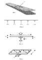
- the aircraft component 11 is composed of the five stiffener panels ST1, ST2, ST3, ST4, ST5 shown in Figures 2, 3 and 4 .
- the aim of this step is to estimate the amount of the component weight that is driven by each design criteria because the change of a material mechanical property can make that an initial non critical criteria becomes critical and this could affect the final weight of the aircraft component.
- a fictitious weight will be used to know which amount of the structure weight is driven by each design criteria. This fictitious weight is calculated from the weight of each main primary structural element taking into account the relative importance of their critical design criteria. The fictitious weight allows estimating the amount of the main primary structure total weight that is driven by each design criteria. Once this fictitious weights are obtained, it will easy to know what are the main design criteria and how they influence the weight of the component because the interactions between weights and design criteria are shown.
- the Design Criteria Weight the amount of the weight of each element j that is driven by each design criteria i (hereinafter also referred as the Design Criteria Weight) is obtained through the following sub-steps:
- n is a factor that is able to determine which criteria from RF>1 can be considered without effect on weight: If n ⁇ infinite, only the first main RF is taken into account. If n ⁇ finite, more than the first main RF is taken into account.
- the parameter n is able to determine which criteria from RF>1 can be considered without effect on weight
- f(Mspc, Mpsa) relates to the dependency between Mspc (the weight of the whole primary structure) and Mpsa (the weight of the main primary structure).
- Mspc the weight of the whole primary structure
- Mpsa the weight of the main primary structure
- this relationship takes the form of a linear function because the weight of the non main primary structure is usually expressed as a percentage of the main primary structure weight.
- any other function can be used if it is required.
- the buckling criteria in this particular case, seems to be the criteria to be considered for a variation in the material properties.
- an increase in the elastic modulus (Ex) of the fiber of the composite material should produce a lighter weight.
- a great improvement of weight is not to be expected because the minimum thickness criteria has an important influence and thickness can not be reduced very much.
- the weight effect of a material property variation (such as the above-mentioned increase of the elastic modulus of the fiber of the composite material) is obtained by means of an extrapolation of the design criteria weights resulting from the previous step in two sub-steps:
- Figures 6 , 7, 8 and 9 show relations between the variation of the element thickness and the variation of the Reserve Factors (RF) associated to four Design Criteria. In all cases there is an inverse proportional relation between those variables.
- RF Reserve Factors
- the inverse proportional relationship is discrete due to the discrete steps on composite properties due to the finite steps of thickness on composite plies.
- a certain penalty threshold due to these discrete steps can be added at this relationship that if the improvement of material is below this threshold the weight of the component is not affected.
- the two type of functions used in this step are based on the global objective of producing a safe structure with the minimum weight, so they follow the principle of modifying the dimensions to lead the RFi to the minimum safe value (normally close to 1.0 for minimum weight). Following this objective no structure weight is added unnecessary.
- This method can be applied component by component up to total aircraft level and the resulting information can help the aircraft manufacturing companies to establish the requirements for improvement of materials to be used in future aircrafts. In this way reduction weight could be known "a priori", and material enhancement efforts could be oriented in the more efficient way.
Landscapes
- Engineering & Computer Science (AREA)
- Manufacturing & Machinery (AREA)
- Transportation (AREA)
- Aviation & Aerospace Engineering (AREA)
- Tires In General (AREA)
- Moulding By Coating Moulds (AREA)
Abstract
Description
- The present invention refers to methods for estimating the effect of the variation of design variables on the weight of an aircraft component and more in particular for estimating the effect of variations of material properties.
- Estimating the weight impact due to a variation of a design variable, particularly a material property, is a very common work performed in the design phase of an aircraft when the designer search for an optimized structure. Material improvements can drastically reduce the structural weight and, therefore, diminish the operating costs of the aircraft. Thus, the improvement of the mechanical properties of the manufacturing materials of aircrafts, particularly composite materials, is a permanent goal for aircraft manufacturers. In fact, huge amounts of money are invested in material research.
- However, material improvements will not necessary lead to significant weight reductions. The final weight of a component is the addition of its structural weight and its non-structural weight. The structural weight is driven by the final thickness of its structural elements. From one side, this thickness is related to the structural failures cases that are driven by the material properties, but they are also driven by other requirements that are independent of material properties, so it is difficult to establish a direct relation between the material properties and the structural and overall final weight. Interaction among different failure modes, design constraints, manufacturability and other factors make the relation between material properties and weight difficult to analyze. For instance, if a thin walled structure is sized with a minimum manufacturable thickness, whatever improvement of the Young's module of the material will not have any impact in the structure weight.
- Therefore, before launching a campaign for any material improvement a previous analysis would be desirable to avoid spending a lot of money without obtaining the expected weight reduction. However a detailed analysis of the structure for each possible configuration of the material is so expensive than sometimes the investment becomes unacceptable. Consequently the decisions regarding material improvement programs not always are supported by technical reasons.
- The present invention is intended to solve this drawback.
- It is an object of the present invention to provide methods for estimating the effect of the variation of design variables on the weight of an aircraft component at reasonable costs.
- It is another object of the present invention to provide methods for estimating the effect of the variation of design variables on the weight of an aircraft component without recalculating a new detailed sizing.
- These and other objects are met by providing a method of designing an aircraft component formed by j elements that includes a phase to estimate the effect of a variation of a design variable on the component weight comprising the following steps:
- a) Providing the main primary structure basic data of the aircraft component and the Reserve Factors (RFij) associated to its design criteria i.
- b) Obtaining a breakdown of the component weight by said design criteria.
- c) Obtaining the weight effect of a design variable variation.
- In a preferred embodiment said step b) includes a sub-step for assigning a fictitious weight (mefRFij) to each element design criteria i as a function of the element j weight (meaj) and a parameter n able to determine which criteria from RF>1 can be considered without effect on weight according to the following equation:

- In another preferred embodiment said step c) includes a first sub-step for recalculating the Reserve Factors (RFij) using suitable functions regarding the relation between the variation of said Reserve Factors (RFij) and the variation of said design variable and a second sub-step for recalculating the component weight using suitable functions regarding the relation between the variation of the element dimensions and the variation of said Reserve Factors (RFij). Hereby an extrapolation of the design criteria weights for the variation of design variables using said functions is facilitated, allowing the estimation of the effect of the variation of design variables on the weight of an aircraft component without recalculating a new detailed sizing.
- In another preferred embodiment, said design variable in one of the following: a material property, a minimum manufacturable thickness, a load applied to the aircraft component. Hereby methods for estimating the effect on the weight of an aircraft component of variations of relevant design variables are achieved.
- Other characteristics and advantages of the present invention will be clear from the following detailed description of embodiments illustrative of its object in relation to the attached figures.
-
-
Figure 1 shows an aircraft component in the torsion box of an horizontal tail plane which is used as an example in the description of a preferred embodiment of this invention. -
Figure 2 is a cross section of the aircraft component ofFigure 1 . -
Figures 3 and 4 are, respectively, a cross section and a perspective view of a single stiffener panel of the aircraft component ofFigure 1 . -
Figure 5 show the variation of the Reserve Factors (RF) corresponding to two Design Criteria vs. the variation of the Elastic Module (Ex) of the material. -
Figures 6 ,7, 8 and 9 show curves representing the variation of the element thickness vs. the variation of the Reserve Factor (RF) associated to four Design Criteria. - The weight of an aircraft component made in a given material such a composite material or a metallic material is greatly dependant of its structural element dimensions. Those dimensions are driven by different design criteria, some of which are related to the mechanical properties of the materials like maximum allowable strength, allowable deformations or stability. Other criteria are independent of the mechanical properties of the material like minimum manufacturable thickness, reparability or manufacturing simplicity.
- As there is no a direct relationship between weight and the main design criteria it is difficult to estimate the effect on weight of a variation in a given design variable. Thus, the aim of this invention is to provide simple methods to evaluate the influence on the aircraft component weight of any variation of material properties or any other variable that could affect any design criteria or a group of them, such a minimum manufacturable thickness criteria or the loads applied to the aircraft component.
- The detailed description of this invention will refer to a method for estimating in an aircraft component the effect of a variation of the material properties on the component weight. Similar methods will achieve the same result for the variation of any other design variable as the skilled man will easily understand.
- It is important to note that this method is applicable to variations of material properties -or any other design variable- in a range that do not modify the global behaviour and failure modes of the structure under consideration.
- In this description, the following terminology will be used.
- An aircraft component shall be understood as an aircraft component made of j elements. The full aircraft can be also considered included under this term.
- The primary structure of an aircraft component is the aircraft component structure necessary for the aircraft could fly and it is the structure affected by the material properties analysed in this embodiment of the invention. For example, if the aircraft component is an horizontal tail stabilizer (HTP) the HTP torsion box belongs to the primary structure.
- The main primary structure is the simplified representation of the primary structure that it is considered in stress analysis.
- The secondary structure of an aircraft component includes those elements which would not cause the aircraft destruction in case of failure such as an HTP fairing. It is not affected by the material properties analysed in this embodiment of the invention but shall be taken into account because its contribution to the aircraft component weight.
- The method according to the preferred embodiment of the invention comprises three basic steps:
- a) Providing the main primary structure basic data of the aircraft component and the Reserve Factors (RFij) associated to its design criteria i.
- b) Obtaining a breakdown of the component weight by said design criteria i.
- c) Obtaining the weight effect of a design variable variation.
- In this step all relevant geometry data, material properties data, and designing criteria data regarding the aircraft component under consideration are provided.
- As an example of the aircraft component we will refer along this description to the
component 11 shown inFigure 1 which is a group of primary structure elements of the upper panel of the box of an HTP. - The
aircraft component 11 is composed of the five stiffener panels ST1, ST2, ST3, ST4, ST5 shown inFigures 2, 3 and 4 . - The detailed geometry of these panels is given in the following table.
Table 1 Geometry data (mm) STR1 STR2 STR3 STR4 STR5 Hw (Height Web) 40 50 32 50 40 Lf (Length Foot) 55 65 55 65 55 Ll (Length Panel Left) 90 90 100 90 90 Lr (Length Panel Right) 90 90 100 90 90 Lt (Total Length) 600 600 600 600 600 Tp (Thickness Panel) 2.76 3 3.6 3 2.76 Ts (Thickness Stringer) 1.84 2 1.4 2 1.84 - The design criteria taken into account are:
- Damage tolerance (DT), local buckling of panels (LBP), local buckling of stiffener web (LBW), column buckling (CB), as design criteria dependant on mechanical properties.
- Minimum thickness (MT) as a design criteria independent of mechanical properties.
- The associated Reserve Factors of said design criteria are given in the following table.
Table 2 Reserve Factors DT LBP LBW CB MT ST1 1.83 1.09073257 1.20 1.06870033 1.5 ST2 2.14 1.70459419 1.06 1.01266839 1.63043478 ST3 2.28 1.21269814 1.35 1.00928461 1.95652174 ST4 2.14 1.70459419 1.06 1.01266839 1.63043478 ST5 1.83 1.09073257 1.20 1.06870033 1.5 - Critical loads applied to the panels (see
Figure 4 ) are shown in the following table.Table 3 Critical loads STR1 STR2 STR3 STR4 STR5 Px (N) -100000 -100000 -100000 -100000 -100000 FxyP1 (N mm) 150 150 150 150 150 FxyP2 (N mm) 150 150 150 150 150 - The aim of this step is to estimate the amount of the component weight that is driven by each design criteria because the change of a material mechanical property can make that an initial non critical criteria becomes critical and this could affect the final weight of the aircraft component.
- A fictitious weight will be used to know which amount of the structure weight is driven by each design criteria. This fictitious weight is calculated from the weight of each main primary structural element taking into account the relative importance of their critical design criteria. The fictitious weight allows estimating the amount of the main primary structure total weight that is driven by each design criteria. Once this fictitious weights are obtained, it will easy to know what are the main design criteria and how they influence the weight of the component because the interactions between weights and design criteria are shown.
- Considering, in general terms, that the aircraft component is composed by j main primary elements and that i design criteria are taken into account, the amount of the weight of each element j that is driven by each design criteria i (hereinafter also referred as the Design Criteria Weight) is obtained through the following sub-steps:
- b1) Calculation of total structural weight from main primary elements:

- The weight of each main primary element is calculated from its dimensions and the density of the material. The result of said calculation for the above-mentioned example is shown in the following table.
Table 4 Initial Weight (Kg) STR1 STR2 STR3 STR4 STR5 Total 0.715 0.835 0.851 0.835 0.715 3.952 - b2) Calculation of design criteria fictitious weights for each element j:

- n is a factor that is able to determine which criteria from RF>1 can be considered without effect on weight:
If n → infinite, only the first main RF is taken into account.
If n → finite, more than the first main RF is taken into account. - Normalization with respect to the critical RF is done so the critical is always 1.0
- b3) Calculation of the fictitious weight of each element j:

- This function allows taking into account not only the effect of critical design criteria but also those design criteria close to the critical. The parameter n is able to determine which criteria from RF>1 can be considered without effect on weight
- b4) Calculation of total fictitious weight:

- b5) Calculation of design criteria i fictitious weight for main primary structure:

- b6) Calculation of design criteria i weight for the main primary structure:

- b7) Calculation of design criteria i weight for the primary structure:

- f(Mspc, Mpsa) relates to the dependency between Mspc (the weight of the whole primary structure) and Mpsa (the weight of the main primary structure). Typically, this relationship takes the form of a linear function because the weight of the non main primary structure is usually expressed as a percentage of the main primary structure weight. However, any other function can be used if it is required.
- b8) Calculation of design criteria i weight for the structural part of the component:

- Again the function f(Msc, Mspc) takes the form that the designer consider more appropriate to express the relationship between Msc (the weight of the structural part of the component) and Mspc (the weight of the whole primary structure).
- b9) Calculation of design criteria i weight for the whole aircraft component:

- Again the function f(Mc, Msc) takes the form that the designer consider more appropriate to express the relationship between Mc (the weight of the whole aircraft component) and Msc (the weight of the structural part of the component).
- The final results of this step in the above-mentioned example are shown in the following table:
Table 5 Design Criteria Weights DT LBP LBW CB MT Total ST1 0.0379 0.1634 0.1889 0.1224 0,2028 0.7154 ST2 0.0291 0,1269 0.2766 0.1260 0,2766 0.8352 ST3 0.0216 0,1355 0.2478 0.1363 0.3099 0.8511 ST4 0.0379 0,1269 0.2766 0.1260 0.2766 0.8352 ST5 0.0379 0,1634 0.1889 0.1224 0.2028 0.7154 Total 0.1557 0,7160 1.1788 0.6331 1.2687 3,9523 % 3.94% 18.12% 29.83% 16.02% 32.10% - In view of these results it can be concluded that local buckling (LBP and LBW) is determinant in terms of weight: 29.83% + 18,12 % = 47,95% of the weight is driven by this criteria. Minimum thickness (MT) is also important (32,10% of the weight). Damage tolerance is not very critical in this example (only 3,94% of the weight).
- Consequently the most important criteria in terms of weight, i.e. the buckling criteria in this particular case, seems to be the criteria to be considered for a variation in the material properties. As it is well known that the buckling criteria improve with the compression stiffness of the structure, an increase in the elastic modulus (Ex) of the fiber of the composite material should produce a lighter weight. However a great improvement of weight is not to be expected because the minimum thickness criteria has an important influence and thickness can not be reduced very much.
- In this step the weight effect of a material property variation (such as the above-mentioned increase of the elastic modulus of the fiber of the composite material) is obtained by means of an extrapolation of the design criteria weights resulting from the previous step in two sub-steps:
- c1) Recalculating the Reserve Factors (RFij) using suitable functions regarding the relation between the variation of said Reserve Factors (RFij) and the variation of the material property.
- The two lineal functions shown in
Figure 5 are functions regarding the variation of the Reserve Factors (RF) corresponding to two Design Criteria and the variation of the Elastic Module (Ex) of the material. In the rest of Design Criteria the Reserve Factors (RF) also grows proportionally to the Elastic Module (Ex). - With an improvement of 12% on the Elastic Module and using said functions the new Reserve Factors (RFi) shown in the following table are obtained:
Table 6 New Reserve Factors DT LBP LBW CB MT ST1 2.05 1.22604886 1.34 1.19199985 1.5 ST2 2.41 1.91606614 1.19 1.12950331 1.63043478 ST3 2.56 1.36314547 1.52 1.12572914 1.95652174 ST4 2.41 1.91606614 1.19 1.12950331 1.63043478 ST5 2.05 1.22604886 1.34 1.19199985 1.5 - c2) Recalculating the component weight using suitable functions regarding the relation between the variation of the element dimensions and said Reserve Factors (RFij)
-
Figures 6 ,7, 8 and 9 show relations between the variation of the element thickness and the variation of the Reserve Factors (RF) associated to four Design Criteria. In all cases there is an inverse proportional relation between those variables. - It can be also considered that the inverse proportional relationship is discrete due to the discrete steps on composite properties due to the finite steps of thickness on composite plies. A certain penalty threshold due to these discrete steps can be added at this relationship that if the improvement of material is below this threshold the weight of the component is not affected.
- Using these relations the following variation of weight are obtained:
Table 7 New Design Criteria Weights DT LBP LBW CB MT Total ST1 0.0337 0.1571 0.1817 0.1170 0,2028 0.6923 ST2 0.0259 0.1220 0.2660 0.1204 0,2766 0.8110 ST3 0.0192 0.1303 0.2383 0.1303 0.3099 0.8281 ST4 0.0259 0.1220 0.2660 0.1204 0.2766 0.8110 ST5 0.0337 0.1571 0.1817 0.1170 0.2028 0.6923 Total 0.1385 0.6887 1.1337 0.60551 1.2687 3,835 % 3.50% 17.42% 28.69% 15.31% 32.10% - In view of this results it can be concluded that in the example under consideration an improvement of 12% on the Elastic Module (Ex) is producing a reduction of weight in the selected structural elements of only 3% (3,835 Kg against 3,9523 Kg). This is a counter-intuitive conclusion because in principle a higher reduction was expected due to the great improvement of the material (12%). The method shows that the weight reduction is not important because of the great influence of the minimum thickness criteria and consequently that any effort to improve the material Elastic Module would not be justified.
- The two type of functions used in this step are based on the global objective of producing a safe structure with the minimum weight, so they follow the principle of modifying the dimensions to lead the RFi to the minimum safe value (normally close to 1.0 for minimum weight). Following this objective no structure weight is added unnecessary.
- This method can be applied component by component up to total aircraft level and the resulting information can help the aircraft manufacturing companies to establish the requirements for improvement of materials to be used in future aircrafts. In this way reduction weight could be known "a priori", and material enhancement efforts could be oriented in the more efficient way.
- Modifications may be introduced into the preferred embodiment just set forth, which are comprised within the scope defined by the following claims.
Claims (8)
- A method of designing an aircraft component formed by a number of elements (j), characterized by including a phase to estimate the effect of a variation of a design variable on the component weight comprising the following steps:a) providing the main primary structure basic data of the aircraft component and the Reserve Factors (RFij) associated to its design criteria (i);b) obtaining a breakdown of the component weight by said design criteria (i);c) obtaining the weight effect of a design variable variation.
- A method of designing an aircraft component according to claim 1, characterized in that said step b) includes a sub-step for assigning a fictitious weight (mefRFij) to each element design criteria (i) as a function of the weight (meaj) of each element (j) and of a parameter (n) able to determine which criteria from RF>1 can be considered without effect on weight according to the following equation:

- A method of designing an aircraft component according to any of claims 1-2, characterized in that said step c) includes a first sub-step for recalculating the Reserve Factors (RFij) using suitable functions regarding the relation between the variation of said Reserve Factors (RFij) and the variation of said design variable and a second sub-step for recalculating the component weight using suitable functions regarding the relation between the variation of the element (j) dimensions and the variation of said Reserve Factors (RFij).
- A method of designing an aircraft component according to any of claims 1-3 characterized in that said design variable is one of the following: a material property, a minimum thickness, a load applied to the aircraft component.
- A method of designing an aircraft component according to any of claims 1-4, characterized in that said design criteria (i) include criteria dependant of material properties.
- A method of designing an aircraft component according to claim 5, characterized in that said design criteria (i) includes one or more of the following: damage tolerance, local buckling, global buckling.
- A method of designing an aircraft component according to any of claims 1-6, characterized in that said design criteria (i) include criteria independent of material properties.
- A method of designing an aircraft component according to claim 7, characterized in that said design criteria (i) includes the minimum manufacturable thickness.
Applications Claiming Priority (2)
| Application Number | Priority Date | Filing Date | Title |
|---|---|---|---|
| ES200803725 | 2008-12-29 | ||
| PCT/ES2009/070634 WO2010076363A1 (en) | 2008-12-29 | 2009-12-29 | Methods for estimating the effect of variations in design variables on the weight of an aircraft component |
Publications (2)
| Publication Number | Publication Date |
|---|---|
| EP2383187A1 true EP2383187A1 (en) | 2011-11-02 |
| EP2383187B1 EP2383187B1 (en) | 2015-07-08 |
Family
ID=42173934
Family Applications (1)
| Application Number | Title | Priority Date | Filing Date |
|---|---|---|---|
| EP09810848.3A Not-in-force EP2383187B1 (en) | 2008-12-29 | 2009-12-29 | Methods for estimating the effect of variations in design variables on the weight of an aircraft component |
Country Status (4)
| Country | Link |
|---|---|
| US (1) | US8577657B2 (en) |
| EP (1) | EP2383187B1 (en) |
| ES (1) | ES2549384T3 (en) |
| WO (1) | WO2010076363A1 (en) |
Families Citing this family (2)
| Publication number | Priority date | Publication date | Assignee | Title |
|---|---|---|---|---|
| CN112660410B (en) * | 2020-12-29 | 2022-11-01 | 中国航空工业集团公司西安飞机设计研究所 | A Method for Estimating Wing Weight with Large Aspect Ratio |
| CN115048729B (en) * | 2022-08-15 | 2022-12-09 | 中国航空工业集团公司西安飞机设计研究所 | Aircraft electrical system weight prediction method |
Family Cites Families (6)
| Publication number | Priority date | Publication date | Assignee | Title |
|---|---|---|---|---|
| CA2004024A1 (en) | 1988-12-22 | 1990-06-22 | Duane M. Cox | Method of developing and making an article having a pre-determined reliability level |
| US7621482B2 (en) * | 2005-11-15 | 2009-11-24 | The Boeing Company | Weight optimized pressurizable aircraft fuselage structures having near elliptical cross sections |
| DE102005063073A1 (en) | 2005-12-29 | 2007-07-12 | Airbus Deutschland Gmbh | Method of sizing and fabricating stiffened structural components, use of structural condition sensors and aircraft |
| US7508910B2 (en) | 2006-05-04 | 2009-03-24 | The Boeing Company | System and methods for x-ray backscatter reverse engineering of structures |
| WO2007139953A2 (en) * | 2006-05-26 | 2007-12-06 | Fatigue Technology, Inc. | Elongated member/radially expandable member assembly and methods of assembling the same |
| DE102007042752B4 (en) * | 2007-09-07 | 2009-06-04 | Deutsches Zentrum für Luft- und Raumfahrt e.V. | Method for analyzing the reliability of technical installations using physical models |
-
2009
- 2009-03-03 US US12/397,028 patent/US8577657B2/en not_active Expired - Fee Related
- 2009-12-29 EP EP09810848.3A patent/EP2383187B1/en not_active Not-in-force
- 2009-12-29 ES ES09810848.3T patent/ES2549384T3/en active Active
- 2009-12-29 WO PCT/ES2009/070634 patent/WO2010076363A1/en not_active Ceased
Non-Patent Citations (1)
| Title |
|---|
| See references of WO2010076363A1 * |
Also Published As
| Publication number | Publication date |
|---|---|
| ES2549384T3 (en) | 2015-10-27 |
| WO2010076363A1 (en) | 2010-07-08 |
| US8577657B2 (en) | 2013-11-05 |
| US20100169054A1 (en) | 2010-07-01 |
| EP2383187B1 (en) | 2015-07-08 |
Similar Documents
| Publication | Publication Date | Title |
|---|---|---|
| Juhász et al. | The effect of delamination on the critical buckling force of composite plates: Experiment and simulation | |
| Ovesy et al. | Post-buckling analysis of delaminated composite laminates with multiple through-the-width delaminations using a novel layerwise theory | |
| EP2383187B1 (en) | Methods for estimating the effect of variations in design variables on the weight of an aircraft component | |
| Engelstad et al. | Assessment of composite damage growth tools for aircraft structure-part I | |
| Garifullin et al. | Initial axial stiffness of welded RHS T joints | |
| Bouazizi et al. | Mechanical response of a hexagonal grid stiffened design of a pressurized cylindrical shell-application to aircraft fuselage | |
| Cid et al. | Probability-damage approach for fail-safe design optimization (PDFSO) | |
| Joo et al. | Introduction of developing fatigue load spectrum for full-scale fatigue test of composite aircraft | |
| CN111274670B (en) | Shaft pressure bearing capacity test design method for titanium alloy profile combined wallboard | |
| Erden et al. | Finite element stress analysis of airplane seat | |
| Wennberg et al. | Orthotropic models of corrugated sheets in finite element analysis | |
| Vasilopoulos et al. | Seismic design of space steel frames using advanced static inelastic (pushover) analysis | |
| Ferreira Filho et al. | Linear buckling behavior of longitudinally singly-and multi-stiffened steel plates under normal and shear stresses | |
| D'Anna et al. | Estimating fatigue reliability of structural components via a Birnbaum-Saunders model with stress dependent parameters from accelerated life data | |
| Ribeiro Soares da Cunha et al. | A robustness-based design strategy for composite structures | |
| Özakça et al. | Buckling and post-buckling of sub-stiffened or locally tailored aluminium panels | |
| Nelson et al. | Strict product liability and safety: Evidence from the general aviation market | |
| James et al. | Finite element analysis of inter spar ribs of composite wing of light transport aircraft against brazier load | |
| Hegde et al. | Effect of honeycomb geometrical parameters on equivalent radiated power and frequency response of motor casing and gearbox surface of a powertrain | |
| Taylor et al. | Using optimization for structural analysis productivity improvement on the F-35 lightning II | |
| Przekop | Repair concepts as design constraints of a stiffened composite PRSEUS panel | |
| Nomura et al. | Improvement of BIW NVH characteristics using a concurrent design optimization approach | |
| Masaoka et al. | Compressive strength of stiffened plates with imperfections: Simple design equations | |
| Malek et al. | A comparative study of design standards for assessment of long-span steel-timber composite floors under human-induced vibration | |
| Toffol et al. | Passive method for dynamic loads alleviation using structural buckling in a composite wing |
Legal Events
| Date | Code | Title | Description |
|---|---|---|---|
| PUAI | Public reference made under article 153(3) epc to a published international application that has entered the european phase |
Free format text: ORIGINAL CODE: 0009012 |
|
| 17P | Request for examination filed |
Effective date: 20110729 |
|
| AK | Designated contracting states |
Kind code of ref document: A1 Designated state(s): AT BE BG CH CY CZ DE DK EE ES FI FR GB GR HR HU IE IS IT LI LT LU LV MC MK MT NL NO PL PT RO SE SI SK SM TR |
|
| DAX | Request for extension of the european patent (deleted) | ||
| GRAP | Despatch of communication of intention to grant a patent |
Free format text: ORIGINAL CODE: EPIDOSNIGR1 |
|
| INTG | Intention to grant announced |
Effective date: 20150206 |
|
| GRAS | Grant fee paid |
Free format text: ORIGINAL CODE: EPIDOSNIGR3 |
|
| GRAA | (expected) grant |
Free format text: ORIGINAL CODE: 0009210 |
|
| AK | Designated contracting states |
Kind code of ref document: B1 Designated state(s): AT BE BG CH CY CZ DE DK EE ES FI FR GB GR HR HU IE IS IT LI LT LU LV MC MK MT NL NO PL PT RO SE SI SK SM TR |
|
| REG | Reference to a national code |
Ref country code: GB Ref legal event code: FG4D |
|
| REG | Reference to a national code |
Ref country code: AT Ref legal event code: REF Ref document number: 735186 Country of ref document: AT Kind code of ref document: T Effective date: 20150715 Ref country code: CH Ref legal event code: EP |
|
| REG | Reference to a national code |
Ref country code: IE Ref legal event code: FG4D |
|
| REG | Reference to a national code |
Ref country code: DE Ref legal event code: R096 Ref document number: 602009032143 Country of ref document: DE |
|
| REG | Reference to a national code |
Ref country code: ES Ref legal event code: FG2A Ref document number: 2549384 Country of ref document: ES Kind code of ref document: T3 Effective date: 20151027 |
|
| REG | Reference to a national code |
Ref country code: AT Ref legal event code: MK05 Ref document number: 735186 Country of ref document: AT Kind code of ref document: T Effective date: 20150708 |
|
| REG | Reference to a national code |
Ref country code: NL Ref legal event code: MP Effective date: 20150708 |
|
| REG | Reference to a national code |
Ref country code: FR Ref legal event code: PLFP Year of fee payment: 7 |
|
| REG | Reference to a national code |
Ref country code: LT Ref legal event code: MG4D |
|
| PG25 | Lapsed in a contracting state [announced via postgrant information from national office to epo] |
Ref country code: FI Free format text: LAPSE BECAUSE OF FAILURE TO SUBMIT A TRANSLATION OF THE DESCRIPTION OR TO PAY THE FEE WITHIN THE PRESCRIBED TIME-LIMIT Effective date: 20150708 Ref country code: GR Free format text: LAPSE BECAUSE OF FAILURE TO SUBMIT A TRANSLATION OF THE DESCRIPTION OR TO PAY THE FEE WITHIN THE PRESCRIBED TIME-LIMIT Effective date: 20151009 Ref country code: NO Free format text: LAPSE BECAUSE OF FAILURE TO SUBMIT A TRANSLATION OF THE DESCRIPTION OR TO PAY THE FEE WITHIN THE PRESCRIBED TIME-LIMIT Effective date: 20151008 Ref country code: LT Free format text: LAPSE BECAUSE OF FAILURE TO SUBMIT A TRANSLATION OF THE DESCRIPTION OR TO PAY THE FEE WITHIN THE PRESCRIBED TIME-LIMIT Effective date: 20150708 Ref country code: LV Free format text: LAPSE BECAUSE OF FAILURE TO SUBMIT A TRANSLATION OF THE DESCRIPTION OR TO PAY THE FEE WITHIN THE PRESCRIBED TIME-LIMIT Effective date: 20150708 |
|
| PG25 | Lapsed in a contracting state [announced via postgrant information from national office to epo] |
Ref country code: PT Free format text: LAPSE BECAUSE OF FAILURE TO SUBMIT A TRANSLATION OF THE DESCRIPTION OR TO PAY THE FEE WITHIN THE PRESCRIBED TIME-LIMIT Effective date: 20151109 Ref country code: SE Free format text: LAPSE BECAUSE OF FAILURE TO SUBMIT A TRANSLATION OF THE DESCRIPTION OR TO PAY THE FEE WITHIN THE PRESCRIBED TIME-LIMIT Effective date: 20150708 Ref country code: HR Free format text: LAPSE BECAUSE OF FAILURE TO SUBMIT A TRANSLATION OF THE DESCRIPTION OR TO PAY THE FEE WITHIN THE PRESCRIBED TIME-LIMIT Effective date: 20150708 Ref country code: PL Free format text: LAPSE BECAUSE OF FAILURE TO SUBMIT A TRANSLATION OF THE DESCRIPTION OR TO PAY THE FEE WITHIN THE PRESCRIBED TIME-LIMIT Effective date: 20150708 Ref country code: AT Free format text: LAPSE BECAUSE OF FAILURE TO SUBMIT A TRANSLATION OF THE DESCRIPTION OR TO PAY THE FEE WITHIN THE PRESCRIBED TIME-LIMIT Effective date: 20150708 Ref country code: IS Free format text: LAPSE BECAUSE OF FAILURE TO SUBMIT A TRANSLATION OF THE DESCRIPTION OR TO PAY THE FEE WITHIN THE PRESCRIBED TIME-LIMIT Effective date: 20151108 |
|
| REG | Reference to a national code |
Ref country code: DE Ref legal event code: R097 Ref document number: 602009032143 Country of ref document: DE |
|
| PG25 | Lapsed in a contracting state [announced via postgrant information from national office to epo] |
Ref country code: EE Free format text: LAPSE BECAUSE OF FAILURE TO SUBMIT A TRANSLATION OF THE DESCRIPTION OR TO PAY THE FEE WITHIN THE PRESCRIBED TIME-LIMIT Effective date: 20150708 Ref country code: DK Free format text: LAPSE BECAUSE OF FAILURE TO SUBMIT A TRANSLATION OF THE DESCRIPTION OR TO PAY THE FEE WITHIN THE PRESCRIBED TIME-LIMIT Effective date: 20150708 Ref country code: SK Free format text: LAPSE BECAUSE OF FAILURE TO SUBMIT A TRANSLATION OF THE DESCRIPTION OR TO PAY THE FEE WITHIN THE PRESCRIBED TIME-LIMIT Effective date: 20150708 Ref country code: IT Free format text: LAPSE BECAUSE OF FAILURE TO SUBMIT A TRANSLATION OF THE DESCRIPTION OR TO PAY THE FEE WITHIN THE PRESCRIBED TIME-LIMIT Effective date: 20150708 Ref country code: CZ Free format text: LAPSE BECAUSE OF FAILURE TO SUBMIT A TRANSLATION OF THE DESCRIPTION OR TO PAY THE FEE WITHIN THE PRESCRIBED TIME-LIMIT Effective date: 20150708 |
|
| PLBE | No opposition filed within time limit |
Free format text: ORIGINAL CODE: 0009261 |
|
| STAA | Information on the status of an ep patent application or granted ep patent |
Free format text: STATUS: NO OPPOSITION FILED WITHIN TIME LIMIT |
|
| PG25 | Lapsed in a contracting state [announced via postgrant information from national office to epo] |
Ref country code: RO Free format text: LAPSE BECAUSE OF FAILURE TO SUBMIT A TRANSLATION OF THE DESCRIPTION OR TO PAY THE FEE WITHIN THE PRESCRIBED TIME-LIMIT Effective date: 20150708 Ref country code: BE Free format text: LAPSE BECAUSE OF NON-PAYMENT OF DUE FEES Effective date: 20151231 |
|
| 26N | No opposition filed |
Effective date: 20160411 |
|
| PG25 | Lapsed in a contracting state [announced via postgrant information from national office to epo] |
Ref country code: MC Free format text: LAPSE BECAUSE OF FAILURE TO SUBMIT A TRANSLATION OF THE DESCRIPTION OR TO PAY THE FEE WITHIN THE PRESCRIBED TIME-LIMIT Effective date: 20150708 Ref country code: LU Free format text: LAPSE BECAUSE OF FAILURE TO SUBMIT A TRANSLATION OF THE DESCRIPTION OR TO PAY THE FEE WITHIN THE PRESCRIBED TIME-LIMIT Effective date: 20151229 |
|
| REG | Reference to a national code |
Ref country code: CH Ref legal event code: PL |
|
| PG25 | Lapsed in a contracting state [announced via postgrant information from national office to epo] |
Ref country code: SI Free format text: LAPSE BECAUSE OF FAILURE TO SUBMIT A TRANSLATION OF THE DESCRIPTION OR TO PAY THE FEE WITHIN THE PRESCRIBED TIME-LIMIT Effective date: 20150708 |
|
| REG | Reference to a national code |
Ref country code: IE Ref legal event code: MM4A |
|
| PG25 | Lapsed in a contracting state [announced via postgrant information from national office to epo] |
Ref country code: CH Free format text: LAPSE BECAUSE OF NON-PAYMENT OF DUE FEES Effective date: 20151231 Ref country code: IE Free format text: LAPSE BECAUSE OF NON-PAYMENT OF DUE FEES Effective date: 20151229 Ref country code: LI Free format text: LAPSE BECAUSE OF NON-PAYMENT OF DUE FEES Effective date: 20151231 |
|
| REG | Reference to a national code |
Ref country code: FR Ref legal event code: PLFP Year of fee payment: 8 |
|
| PG25 | Lapsed in a contracting state [announced via postgrant information from national office to epo] |
Ref country code: BE Free format text: LAPSE BECAUSE OF FAILURE TO SUBMIT A TRANSLATION OF THE DESCRIPTION OR TO PAY THE FEE WITHIN THE PRESCRIBED TIME-LIMIT Effective date: 20150708 |
|
| PG25 | Lapsed in a contracting state [announced via postgrant information from national office to epo] |
Ref country code: BG Free format text: LAPSE BECAUSE OF FAILURE TO SUBMIT A TRANSLATION OF THE DESCRIPTION OR TO PAY THE FEE WITHIN THE PRESCRIBED TIME-LIMIT Effective date: 20150708 Ref country code: HU Free format text: LAPSE BECAUSE OF FAILURE TO SUBMIT A TRANSLATION OF THE DESCRIPTION OR TO PAY THE FEE WITHIN THE PRESCRIBED TIME-LIMIT; INVALID AB INITIO Effective date: 20091229 Ref country code: SM Free format text: LAPSE BECAUSE OF FAILURE TO SUBMIT A TRANSLATION OF THE DESCRIPTION OR TO PAY THE FEE WITHIN THE PRESCRIBED TIME-LIMIT Effective date: 20150708 |
|
| PG25 | Lapsed in a contracting state [announced via postgrant information from national office to epo] |
Ref country code: CY Free format text: LAPSE BECAUSE OF FAILURE TO SUBMIT A TRANSLATION OF THE DESCRIPTION OR TO PAY THE FEE WITHIN THE PRESCRIBED TIME-LIMIT Effective date: 20150708 Ref country code: NL Free format text: LAPSE BECAUSE OF FAILURE TO SUBMIT A TRANSLATION OF THE DESCRIPTION OR TO PAY THE FEE WITHIN THE PRESCRIBED TIME-LIMIT Effective date: 20150708 |
|
| PG25 | Lapsed in a contracting state [announced via postgrant information from national office to epo] |
Ref country code: TR Free format text: LAPSE BECAUSE OF FAILURE TO SUBMIT A TRANSLATION OF THE DESCRIPTION OR TO PAY THE FEE WITHIN THE PRESCRIBED TIME-LIMIT Effective date: 20150708 Ref country code: MT Free format text: LAPSE BECAUSE OF FAILURE TO SUBMIT A TRANSLATION OF THE DESCRIPTION OR TO PAY THE FEE WITHIN THE PRESCRIBED TIME-LIMIT Effective date: 20150708 |
|
| REG | Reference to a national code |
Ref country code: FR Ref legal event code: PLFP Year of fee payment: 9 |
|
| PGFP | Annual fee paid to national office [announced via postgrant information from national office to epo] |
Ref country code: FR Payment date: 20171221 Year of fee payment: 9 Ref country code: DE Payment date: 20171211 Year of fee payment: 9 |
|
| PGFP | Annual fee paid to national office [announced via postgrant information from national office to epo] |
Ref country code: GB Payment date: 20171221 Year of fee payment: 9 |
|
| PGFP | Annual fee paid to national office [announced via postgrant information from national office to epo] |
Ref country code: ES Payment date: 20180124 Year of fee payment: 9 |
|
| PG25 | Lapsed in a contracting state [announced via postgrant information from national office to epo] |
Ref country code: MK Free format text: LAPSE BECAUSE OF FAILURE TO SUBMIT A TRANSLATION OF THE DESCRIPTION OR TO PAY THE FEE WITHIN THE PRESCRIBED TIME-LIMIT Effective date: 20150708 |
|
| REG | Reference to a national code |
Ref country code: DE Ref legal event code: R119 Ref document number: 602009032143 Country of ref document: DE |
|
| GBPC | Gb: european patent ceased through non-payment of renewal fee |
Effective date: 20181229 |
|
| PG25 | Lapsed in a contracting state [announced via postgrant information from national office to epo] |
Ref country code: DE Free format text: LAPSE BECAUSE OF NON-PAYMENT OF DUE FEES Effective date: 20190702 Ref country code: FR Free format text: LAPSE BECAUSE OF NON-PAYMENT OF DUE FEES Effective date: 20181231 |
|
| PG25 | Lapsed in a contracting state [announced via postgrant information from national office to epo] |
Ref country code: GB Free format text: LAPSE BECAUSE OF NON-PAYMENT OF DUE FEES Effective date: 20181229 |
|
| REG | Reference to a national code |
Ref country code: ES Ref legal event code: FD2A Effective date: 20200205 |
|
| PG25 | Lapsed in a contracting state [announced via postgrant information from national office to epo] |
Ref country code: ES Free format text: LAPSE BECAUSE OF NON-PAYMENT OF DUE FEES Effective date: 20181230 |