EP2383057A2 - Flat metal particle-containing composition and heat ray-shielding material - Google Patents
Flat metal particle-containing composition and heat ray-shielding material Download PDFInfo
- Publication number
- EP2383057A2 EP2383057A2 EP11161114A EP11161114A EP2383057A2 EP 2383057 A2 EP2383057 A2 EP 2383057A2 EP 11161114 A EP11161114 A EP 11161114A EP 11161114 A EP11161114 A EP 11161114A EP 2383057 A2 EP2383057 A2 EP 2383057A2
- Authority
- EP
- European Patent Office
- Prior art keywords
- flat metal
- heat ray
- ring
- shielding material
- groups
- Prior art date
- Legal status (The legal status is an assumption and is not a legal conclusion. Google has not performed a legal analysis and makes no representation as to the accuracy of the status listed.)
- Granted
Links
- 239000002923 metal particle Substances 0.000 title claims abstract description 192
- 239000000203 mixture Substances 0.000 title claims abstract description 58
- 239000000463 material Substances 0.000 title claims description 89
- -1 heterocyclic ring compound Chemical class 0.000 claims abstract description 150
- BQCADISMDOOEFD-UHFFFAOYSA-N Silver Chemical compound [Ag] BQCADISMDOOEFD-UHFFFAOYSA-N 0.000 claims abstract description 64
- 229910052709 silver Inorganic materials 0.000 claims abstract description 61
- 239000004332 silver Substances 0.000 claims abstract description 61
- 230000003993 interaction Effects 0.000 claims abstract description 19
- 239000000758 substrate Substances 0.000 claims description 43
- 238000010521 absorption reaction Methods 0.000 claims description 16
- RYGMFSIKBFXOCR-UHFFFAOYSA-N Copper Chemical compound [Cu] RYGMFSIKBFXOCR-UHFFFAOYSA-N 0.000 claims description 3
- 229910045601 alloy Inorganic materials 0.000 claims description 3
- 239000000956 alloy Substances 0.000 claims description 3
- 229910052802 copper Inorganic materials 0.000 claims description 3
- 239000010949 copper Substances 0.000 claims description 3
- PCHJSUWPFVWCPO-UHFFFAOYSA-N gold Chemical compound [Au] PCHJSUWPFVWCPO-UHFFFAOYSA-N 0.000 claims description 3
- 229910052737 gold Inorganic materials 0.000 claims description 3
- 239000010931 gold Substances 0.000 claims description 3
- 239000002245 particle Substances 0.000 description 109
- 239000010410 layer Substances 0.000 description 43
- 238000000034 method Methods 0.000 description 37
- 125000000623 heterocyclic group Chemical group 0.000 description 33
- 238000004519 manufacturing process Methods 0.000 description 30
- 239000011521 glass Substances 0.000 description 21
- 238000002834 transmittance Methods 0.000 description 20
- 239000006185 dispersion Substances 0.000 description 19
- 125000001424 substituent group Chemical group 0.000 description 19
- 238000000576 coating method Methods 0.000 description 17
- 125000000217 alkyl group Chemical group 0.000 description 16
- HEMHJVSKTPXQMS-UHFFFAOYSA-M Sodium hydroxide Chemical compound [OH-].[Na+] HEMHJVSKTPXQMS-UHFFFAOYSA-M 0.000 description 15
- 239000011248 coating agent Substances 0.000 description 15
- 150000001875 compounds Chemical class 0.000 description 15
- SQGYOTSLMSWVJD-UHFFFAOYSA-N silver(1+) nitrate Chemical compound [Ag+].[O-]N(=O)=O SQGYOTSLMSWVJD-UHFFFAOYSA-N 0.000 description 14
- 239000007788 liquid Substances 0.000 description 13
- 238000006722 reduction reaction Methods 0.000 description 12
- 238000002310 reflectometry Methods 0.000 description 11
- 125000003118 aryl group Chemical group 0.000 description 9
- 229910052757 nitrogen Inorganic materials 0.000 description 9
- VYPSYNLAJGMNEJ-UHFFFAOYSA-N Silicium dioxide Chemical compound O=[Si]=O VYPSYNLAJGMNEJ-UHFFFAOYSA-N 0.000 description 8
- 230000000052 comparative effect Effects 0.000 description 8
- 238000011156 evaluation Methods 0.000 description 8
- 239000000047 product Substances 0.000 description 8
- 229920005989 resin Polymers 0.000 description 8
- 239000011347 resin Substances 0.000 description 8
- 239000011230 binding agent Substances 0.000 description 7
- 229910000510 noble metal Inorganic materials 0.000 description 7
- 229910001961 silver nitrate Inorganic materials 0.000 description 7
- XLYOFNOQVPJJNP-UHFFFAOYSA-N water Substances O XLYOFNOQVPJJNP-UHFFFAOYSA-N 0.000 description 7
- OKKJLVBELUTLKV-UHFFFAOYSA-N Methanol Chemical compound OC OKKJLVBELUTLKV-UHFFFAOYSA-N 0.000 description 6
- 229910003087 TiOx Inorganic materials 0.000 description 6
- 125000003342 alkenyl group Chemical group 0.000 description 6
- 125000003277 amino group Chemical group 0.000 description 6
- 238000009826 distribution Methods 0.000 description 6
- 125000004435 hydrogen atom Chemical group [H]* 0.000 description 6
- 125000004433 nitrogen atom Chemical group N* 0.000 description 6
- HLLICFJUWSZHRJ-UHFFFAOYSA-N tioxidazole Chemical compound CCCOC1=CC=C2N=C(NC(=O)OC)SC2=C1 HLLICFJUWSZHRJ-UHFFFAOYSA-N 0.000 description 6
- 239000002270 dispersing agent Substances 0.000 description 5
- 230000000694 effects Effects 0.000 description 5
- 125000005842 heteroatom Chemical group 0.000 description 5
- 238000005259 measurement Methods 0.000 description 5
- 229910052751 metal Inorganic materials 0.000 description 5
- 239000002184 metal Substances 0.000 description 5
- 239000002082 metal nanoparticle Substances 0.000 description 5
- 239000011241 protective layer Substances 0.000 description 5
- 229910052717 sulfur Inorganic materials 0.000 description 5
- CIWBSHSKHKDKBQ-JLAZNSOCSA-N Ascorbic acid Chemical compound OC[C@H](O)[C@H]1OC(=O)C(O)=C1O CIWBSHSKHKDKBQ-JLAZNSOCSA-N 0.000 description 4
- IJGRMHOSHXDMSA-UHFFFAOYSA-N Atomic nitrogen Chemical compound N#N IJGRMHOSHXDMSA-UHFFFAOYSA-N 0.000 description 4
- 125000004414 alkyl thio group Chemical group 0.000 description 4
- 125000000304 alkynyl group Chemical group 0.000 description 4
- 125000004429 atom Chemical group 0.000 description 4
- 125000000656 azaniumyl group Chemical group [H][N+]([H])([H])[*] 0.000 description 4
- 125000003917 carbamoyl group Chemical group [H]N([H])C(*)=O 0.000 description 4
- 238000005260 corrosion Methods 0.000 description 4
- 230000007797 corrosion Effects 0.000 description 4
- 230000003247 decreasing effect Effects 0.000 description 4
- 239000003112 inhibitor Substances 0.000 description 4
- 229910044991 metal oxide Inorganic materials 0.000 description 4
- 150000004706 metal oxides Chemical class 0.000 description 4
- 125000001997 phenyl group Chemical group [H]C1=C([H])C([H])=C(*)C([H])=C1[H] 0.000 description 4
- 125000005328 phosphinyl group Chemical group [PH2](=O)* 0.000 description 4
- 229920002037 poly(vinyl butyral) polymer Polymers 0.000 description 4
- 229920000139 polyethylene terephthalate Polymers 0.000 description 4
- 239000005020 polyethylene terephthalate Substances 0.000 description 4
- BWHMMNNQKKPAPP-UHFFFAOYSA-L potassium carbonate Chemical compound [K+].[K+].[O-]C([O-])=O BWHMMNNQKKPAPP-UHFFFAOYSA-L 0.000 description 4
- 229920006395 saturated elastomer Polymers 0.000 description 4
- 239000000377 silicon dioxide Substances 0.000 description 4
- GEHJYWRUCIMESM-UHFFFAOYSA-L sodium sulfite Chemical compound [Na+].[Na+].[O-]S([O-])=O GEHJYWRUCIMESM-UHFFFAOYSA-L 0.000 description 4
- 125000004434 sulfur atom Chemical group 0.000 description 4
- 229940126062 Compound A Drugs 0.000 description 3
- 108010010803 Gelatin Proteins 0.000 description 3
- NLDMNSXOCDLTTB-UHFFFAOYSA-N Heterophylliin A Natural products O1C2COC(=O)C3=CC(O)=C(O)C(O)=C3C3=C(O)C(O)=C(O)C=C3C(=O)OC2C(OC(=O)C=2C=C(O)C(O)=C(O)C=2)C(O)C1OC(=O)C1=CC(O)=C(O)C(O)=C1 NLDMNSXOCDLTTB-UHFFFAOYSA-N 0.000 description 3
- GRYLNZFGIOXLOG-UHFFFAOYSA-N Nitric acid Chemical compound O[N+]([O-])=O GRYLNZFGIOXLOG-UHFFFAOYSA-N 0.000 description 3
- 238000002835 absorbance Methods 0.000 description 3
- 125000003545 alkoxy group Chemical group 0.000 description 3
- 125000004453 alkoxycarbonyl group Chemical group 0.000 description 3
- 125000004466 alkoxycarbonylamino group Chemical group 0.000 description 3
- 125000005194 alkoxycarbonyloxy group Chemical group 0.000 description 3
- 125000006598 aminocarbonylamino group Chemical group 0.000 description 3
- 125000004397 aminosulfonyl group Chemical group NS(=O)(=O)* 0.000 description 3
- 239000003963 antioxidant agent Substances 0.000 description 3
- 230000003078 antioxidant effect Effects 0.000 description 3
- 235000006708 antioxidants Nutrition 0.000 description 3
- 125000006615 aromatic heterocyclic group Chemical group 0.000 description 3
- 125000005162 aryl oxy carbonyl amino group Chemical group 0.000 description 3
- 125000005161 aryl oxy carbonyl group Chemical group 0.000 description 3
- 125000005135 aryl sulfinyl group Chemical group 0.000 description 3
- 125000004657 aryl sulfonyl amino group Chemical group 0.000 description 3
- 125000004391 aryl sulfonyl group Chemical group 0.000 description 3
- 125000005110 aryl thio group Chemical group 0.000 description 3
- 125000005200 aryloxy carbonyloxy group Chemical group 0.000 description 3
- 125000004104 aryloxy group Chemical group 0.000 description 3
- 150000001602 bicycloalkyls Chemical group 0.000 description 3
- 230000005540 biological transmission Effects 0.000 description 3
- 230000015572 biosynthetic process Effects 0.000 description 3
- 125000001951 carbamoylamino group Chemical group C(N)(=O)N* 0.000 description 3
- KRKNYBCHXYNGOX-UHFFFAOYSA-N citric acid Chemical compound OC(=O)CC(O)(C(O)=O)CC(O)=O KRKNYBCHXYNGOX-UHFFFAOYSA-N 0.000 description 3
- 229910052681 coesite Inorganic materials 0.000 description 3
- 229910052906 cristobalite Inorganic materials 0.000 description 3
- 125000000392 cycloalkenyl group Chemical group 0.000 description 3
- 125000000753 cycloalkyl group Chemical group 0.000 description 3
- 238000001035 drying Methods 0.000 description 3
- 229920000159 gelatin Polymers 0.000 description 3
- 239000008273 gelatin Substances 0.000 description 3
- 235000019322 gelatine Nutrition 0.000 description 3
- 235000011852 gelatine desserts Nutrition 0.000 description 3
- 238000010438 heat treatment Methods 0.000 description 3
- 125000000717 hydrazino group Chemical group [H]N([*])N([H])[H] 0.000 description 3
- 238000007654 immersion Methods 0.000 description 3
- 238000013508 migration Methods 0.000 description 3
- 230000005012 migration Effects 0.000 description 3
- 238000002156 mixing Methods 0.000 description 3
- 239000002073 nanorod Substances 0.000 description 3
- 229910017604 nitric acid Inorganic materials 0.000 description 3
- 230000003647 oxidation Effects 0.000 description 3
- 238000007254 oxidation reaction Methods 0.000 description 3
- 125000001820 oxy group Chemical group [*:1]O[*:2] 0.000 description 3
- 125000004430 oxygen atom Chemical group O* 0.000 description 3
- 229920000642 polymer Polymers 0.000 description 3
- 239000002244 precipitate Substances 0.000 description 3
- 238000001878 scanning electron micrograph Methods 0.000 description 3
- 125000003808 silyl group Chemical group [H][Si]([H])([H])[*] 0.000 description 3
- 229910052682 stishovite Inorganic materials 0.000 description 3
- 238000001308 synthesis method Methods 0.000 description 3
- 229910052905 tridymite Inorganic materials 0.000 description 3
- IANQTJSKSUMEQM-UHFFFAOYSA-N 1-benzofuran Chemical group C1=CC=C2OC=CC2=C1 IANQTJSKSUMEQM-UHFFFAOYSA-N 0.000 description 2
- FCEHBMOGCRZNNI-UHFFFAOYSA-N 1-benzothiophene Chemical group C1=CC=C2SC=CC2=C1 FCEHBMOGCRZNNI-UHFFFAOYSA-N 0.000 description 2
- UXGVMFHEKMGWMA-UHFFFAOYSA-N 2-benzofuran Chemical group C1=CC=CC2=COC=C21 UXGVMFHEKMGWMA-UHFFFAOYSA-N 0.000 description 2
- 229920002284 Cellulose triacetate Polymers 0.000 description 2
- YLQBMQCUIZJEEH-UHFFFAOYSA-N Furan Chemical group C=1C=COC=1 YLQBMQCUIZJEEH-UHFFFAOYSA-N 0.000 description 2
- JUJWROOIHBZHMG-UHFFFAOYSA-N Pyridine Chemical group C1=CC=NC=C1 JUJWROOIHBZHMG-UHFFFAOYSA-N 0.000 description 2
- BUGBHKTXTAQXES-UHFFFAOYSA-N Selenium Chemical group [Se] BUGBHKTXTAQXES-UHFFFAOYSA-N 0.000 description 2
- FZWLAAWBMGSTSO-UHFFFAOYSA-N Thiazole Chemical group C1=CSC=N1 FZWLAAWBMGSTSO-UHFFFAOYSA-N 0.000 description 2
- YTPLMLYBLZKORZ-UHFFFAOYSA-N Thiophene Chemical group C=1C=CSC=1 YTPLMLYBLZKORZ-UHFFFAOYSA-N 0.000 description 2
- XLOMVQKBTHCTTD-UHFFFAOYSA-N Zinc monoxide Chemical compound [Zn]=O XLOMVQKBTHCTTD-UHFFFAOYSA-N 0.000 description 2
- MCMNRKCIXSYSNV-UHFFFAOYSA-N Zirconium dioxide Chemical compound O=[Zr]=O MCMNRKCIXSYSNV-UHFFFAOYSA-N 0.000 description 2
- NNLVGZFZQQXQNW-ADJNRHBOSA-N [(2r,3r,4s,5r,6s)-4,5-diacetyloxy-3-[(2s,3r,4s,5r,6r)-3,4,5-triacetyloxy-6-(acetyloxymethyl)oxan-2-yl]oxy-6-[(2r,3r,4s,5r,6s)-4,5,6-triacetyloxy-2-(acetyloxymethyl)oxan-3-yl]oxyoxan-2-yl]methyl acetate Chemical compound O([C@@H]1O[C@@H]([C@H]([C@H](OC(C)=O)[C@H]1OC(C)=O)O[C@H]1[C@@H]([C@@H](OC(C)=O)[C@H](OC(C)=O)[C@@H](COC(C)=O)O1)OC(C)=O)COC(=O)C)[C@@H]1[C@@H](COC(C)=O)O[C@@H](OC(C)=O)[C@H](OC(C)=O)[C@H]1OC(C)=O NNLVGZFZQQXQNW-ADJNRHBOSA-N 0.000 description 2
- DGEZNRSVGBDHLK-UHFFFAOYSA-N [1,10]phenanthroline Chemical group C1=CN=C2C3=NC=CC=C3C=CC2=C1 DGEZNRSVGBDHLK-UHFFFAOYSA-N 0.000 description 2
- 230000032900 absorption of visible light Effects 0.000 description 2
- 125000000641 acridinyl group Chemical group C1(=CC=CC2=NC3=CC=CC=C3C=C12)* 0.000 description 2
- 125000002252 acyl group Chemical group 0.000 description 2
- 125000004442 acylamino group Chemical group 0.000 description 2
- 125000004423 acyloxy group Chemical group 0.000 description 2
- 239000000654 additive Substances 0.000 description 2
- 125000003282 alkyl amino group Chemical group 0.000 description 2
- 125000001769 aryl amino group Chemical group 0.000 description 2
- 235000010323 ascorbic acid Nutrition 0.000 description 2
- 229960005070 ascorbic acid Drugs 0.000 description 2
- 239000011668 ascorbic acid Substances 0.000 description 2
- 229940075397 calomel Drugs 0.000 description 2
- 125000000609 carbazolyl group Chemical group C1(=CC=CC=2C3=CC=CC=C3NC12)* 0.000 description 2
- 125000002915 carbonyl group Chemical group [*:2]C([*:1])=O 0.000 description 2
- 125000003178 carboxy group Chemical group [H]OC(*)=O 0.000 description 2
- 239000003638 chemical reducing agent Substances 0.000 description 2
- 239000000084 colloidal system Substances 0.000 description 2
- 125000004093 cyano group Chemical group *C#N 0.000 description 2
- 125000004122 cyclic group Chemical group 0.000 description 2
- ZOMNIUBKTOKEHS-UHFFFAOYSA-L dimercury dichloride Chemical compound Cl[Hg][Hg]Cl ZOMNIUBKTOKEHS-UHFFFAOYSA-L 0.000 description 2
- ZUOUZKKEUPVFJK-UHFFFAOYSA-N diphenyl Chemical group C1=CC=CC=C1C1=CC=CC=C1 ZUOUZKKEUPVFJK-UHFFFAOYSA-N 0.000 description 2
- 238000002848 electrochemical method Methods 0.000 description 2
- 230000008014 freezing Effects 0.000 description 2
- 238000007710 freezing Methods 0.000 description 2
- 125000005843 halogen group Chemical group 0.000 description 2
- 125000002887 hydroxy group Chemical group [H]O* 0.000 description 2
- 125000002883 imidazolyl group Chemical group 0.000 description 2
- 125000005462 imide group Chemical group 0.000 description 2
- 125000003406 indolizinyl group Chemical group C=1(C=CN2C=CC=CC12)* 0.000 description 2
- 125000001041 indolyl group Chemical group 0.000 description 2
- 125000002183 isoquinolinyl group Chemical group C1(=NC=CC2=CC=CC=C12)* 0.000 description 2
- 239000007791 liquid phase Substances 0.000 description 2
- 238000003760 magnetic stirring Methods 0.000 description 2
- 239000002105 nanoparticle Substances 0.000 description 2
- 125000001624 naphthyl group Chemical group 0.000 description 2
- 125000000449 nitro group Chemical group [O-][N+](*)=O 0.000 description 2
- 125000002971 oxazolyl group Chemical group 0.000 description 2
- RDOWQLZANAYVLL-UHFFFAOYSA-N phenanthridine Chemical group C1=CC=C2C3=CC=CC=C3C=NC2=C1 RDOWQLZANAYVLL-UHFFFAOYSA-N 0.000 description 2
- 125000001476 phosphono group Chemical group [H]OP(*)(=O)O[H] 0.000 description 2
- LFSXCDWNBUNEEM-UHFFFAOYSA-N phthalazine Chemical group C1=NN=CC2=CC=CC=C21 LFSXCDWNBUNEEM-UHFFFAOYSA-N 0.000 description 2
- 229920002451 polyvinyl alcohol Polymers 0.000 description 2
- 235000019422 polyvinyl alcohol Nutrition 0.000 description 2
- 235000015497 potassium bicarbonate Nutrition 0.000 description 2
- 239000011736 potassium bicarbonate Substances 0.000 description 2
- 229910000028 potassium bicarbonate Inorganic materials 0.000 description 2
- 229910000027 potassium carbonate Inorganic materials 0.000 description 2
- 235000011181 potassium carbonates Nutrition 0.000 description 2
- TYJJADVDDVDEDZ-UHFFFAOYSA-M potassium hydrogencarbonate Chemical compound [K+].OC([O-])=O TYJJADVDDVDEDZ-UHFFFAOYSA-M 0.000 description 2
- 238000012545 processing Methods 0.000 description 2
- 125000003373 pyrazinyl group Chemical group 0.000 description 2
- PBMFSQRYOILNGV-UHFFFAOYSA-N pyridazine Chemical group C1=CC=NN=C1 PBMFSQRYOILNGV-UHFFFAOYSA-N 0.000 description 2
- 125000000714 pyrimidinyl group Chemical group 0.000 description 2
- 125000002943 quinolinyl group Chemical group N1=C(C=CC2=CC=CC=C12)* 0.000 description 2
- 125000001567 quinoxalinyl group Chemical group N1=C(C=NC2=CC=CC=C12)* 0.000 description 2
- 239000011369 resultant mixture Substances 0.000 description 2
- 229910052711 selenium Inorganic materials 0.000 description 2
- 125000004469 siloxy group Chemical group [SiH3]O* 0.000 description 2
- 239000001509 sodium citrate Substances 0.000 description 2
- NLJMYIDDQXHKNR-UHFFFAOYSA-K sodium citrate Chemical compound O.O.[Na+].[Na+].[Na+].[O-]C(=O)CC(O)(CC([O-])=O)C([O-])=O NLJMYIDDQXHKNR-UHFFFAOYSA-K 0.000 description 2
- 235000010265 sodium sulphite Nutrition 0.000 description 2
- 238000001228 spectrum Methods 0.000 description 2
- 238000003756 stirring Methods 0.000 description 2
- 125000000020 sulfo group Chemical group O=S(=O)([*])O[H] 0.000 description 2
- 239000004094 surface-active agent Substances 0.000 description 2
- 238000003786 synthesis reaction Methods 0.000 description 2
- 238000012360 testing method Methods 0.000 description 2
- 125000003396 thiol group Chemical group [H]S* 0.000 description 2
- XOLBLPGZBRYERU-UHFFFAOYSA-N tin dioxide Chemical compound O=[Sn]=O XOLBLPGZBRYERU-UHFFFAOYSA-N 0.000 description 2
- 238000000411 transmission spectrum Methods 0.000 description 2
- 229910052724 xenon Inorganic materials 0.000 description 2
- FHNFHKCVQCLJFQ-UHFFFAOYSA-N xenon atom Chemical compound [Xe] FHNFHKCVQCLJFQ-UHFFFAOYSA-N 0.000 description 2
- 125000000923 (C1-C30) alkyl group Chemical group 0.000 description 1
- FNQJDLTXOVEEFB-UHFFFAOYSA-N 1,2,3-benzothiadiazole Chemical group C1=CC=C2SN=NC2=C1 FNQJDLTXOVEEFB-UHFFFAOYSA-N 0.000 description 1
- SLLFVLKNXABYGI-UHFFFAOYSA-N 1,2,3-benzoxadiazole Chemical group C1=CC=C2ON=NC2=C1 SLLFVLKNXABYGI-UHFFFAOYSA-N 0.000 description 1
- 125000001399 1,2,3-triazolyl group Chemical group N1N=NC(=C1)* 0.000 description 1
- 125000001376 1,2,4-triazolyl group Chemical group N1N=C(N=C1)* 0.000 description 1
- UDGKZGLPXCRRAM-UHFFFAOYSA-N 1,2,5-thiadiazole Chemical group C=1C=NSN=1 UDGKZGLPXCRRAM-UHFFFAOYSA-N 0.000 description 1
- MBIZXFATKUQOOA-UHFFFAOYSA-N 1,3,4-thiadiazole Chemical group C1=NN=CS1 MBIZXFATKUQOOA-UHFFFAOYSA-N 0.000 description 1
- FLBAYUMRQUHISI-UHFFFAOYSA-N 1,8-naphthyridine Chemical group N1=CC=CC2=CC=CN=C21 FLBAYUMRQUHISI-UHFFFAOYSA-N 0.000 description 1
- JAAIPIWKKXCNOC-UHFFFAOYSA-N 1h-tetrazol-1-ium-5-thiolate Chemical compound SC1=NN=NN1 JAAIPIWKKXCNOC-UHFFFAOYSA-N 0.000 description 1
- YQTCQNIPQMJNTI-UHFFFAOYSA-N 2,2-dimethylpropan-1-one Chemical group CC(C)(C)[C]=O YQTCQNIPQMJNTI-UHFFFAOYSA-N 0.000 description 1
- 125000001340 2-chloroethyl group Chemical group [H]C([H])(Cl)C([H])([H])* 0.000 description 1
- 125000001731 2-cyanoethyl group Chemical group [H]C([H])(*)C([H])([H])C#N 0.000 description 1
- 125000002941 2-furyl group Chemical group O1C([*])=C([H])C([H])=C1[H] 0.000 description 1
- 125000003903 2-propenyl group Chemical group [H]C([*])([H])C([H])=C([H])[H] 0.000 description 1
- 125000001494 2-propynyl group Chemical group [H]C#CC([H])([H])* 0.000 description 1
- 125000000175 2-thienyl group Chemical group S1C([*])=C([H])C([H])=C1[H] 0.000 description 1
- 125000004179 3-chlorophenyl group Chemical group [H]C1=C([H])C(*)=C([H])C(Cl)=C1[H] 0.000 description 1
- MWVTWFVJZLCBMC-UHFFFAOYSA-N 4,4'-bipyridine Chemical group C1=NC=CC(C=2C=CN=CC=2)=C1 MWVTWFVJZLCBMC-UHFFFAOYSA-N 0.000 description 1
- DQRKTVIJNCVZAX-UHFFFAOYSA-N 4-(2-pyridin-4-ylethyl)pyridine Chemical group C=1C=NC=CC=1CCC1=CC=NC=C1 DQRKTVIJNCVZAX-UHFFFAOYSA-N 0.000 description 1
- OGNCVVRIKNGJHQ-UHFFFAOYSA-N 4-(3-pyridin-4-ylpropyl)pyridine Chemical group C=1C=NC=CC=1CCCC1=CC=NC=C1 OGNCVVRIKNGJHQ-UHFFFAOYSA-N 0.000 description 1
- 125000002471 4H-quinolizinyl group Chemical group C=1(C=CCN2C=CC=CC12)* 0.000 description 1
- ZCYVEMRRCGMTRW-UHFFFAOYSA-N 7553-56-2 Chemical group [I] ZCYVEMRRCGMTRW-UHFFFAOYSA-N 0.000 description 1
- KDCGOANMDULRCW-UHFFFAOYSA-N 7H-purine Chemical group N1=CNC2=NC=NC2=C1 KDCGOANMDULRCW-UHFFFAOYSA-N 0.000 description 1
- 229920000178 Acrylic resin Polymers 0.000 description 1
- 239000004925 Acrylic resin Substances 0.000 description 1
- 229920002799 BoPET Polymers 0.000 description 1
- ZOXJGFHDIHLPTG-UHFFFAOYSA-N Boron Chemical group [B] ZOXJGFHDIHLPTG-UHFFFAOYSA-N 0.000 description 1
- WKBOTKDWSSQWDR-UHFFFAOYSA-N Bromine atom Chemical group [Br] WKBOTKDWSSQWDR-UHFFFAOYSA-N 0.000 description 1
- 229910004727 OSO3H Inorganic materials 0.000 description 1
- 239000004372 Polyvinyl alcohol Substances 0.000 description 1
- KAESVJOAVNADME-UHFFFAOYSA-N Pyrrole Chemical group C=1C=CNC=1 KAESVJOAVNADME-UHFFFAOYSA-N 0.000 description 1
- RWRDLPDLKQPQOW-UHFFFAOYSA-N Pyrrolidine Chemical group C1CCNC1 RWRDLPDLKQPQOW-UHFFFAOYSA-N 0.000 description 1
- XUIMIQQOPSSXEZ-UHFFFAOYSA-N Silicon Chemical group [Si] XUIMIQQOPSSXEZ-UHFFFAOYSA-N 0.000 description 1
- 125000002777 acetyl group Chemical group [H]C([H])([H])C(*)=O 0.000 description 1
- 239000012790 adhesive layer Substances 0.000 description 1
- 238000004220 aggregation Methods 0.000 description 1
- 230000002776 aggregation Effects 0.000 description 1
- 230000032683 aging Effects 0.000 description 1
- 125000003806 alkyl carbonyl amino group Chemical group 0.000 description 1
- 125000004448 alkyl carbonyl group Chemical group 0.000 description 1
- 125000005196 alkyl carbonyloxy group Chemical group 0.000 description 1
- 125000004644 alkyl sulfinyl group Chemical group 0.000 description 1
- 125000004390 alkyl sulfonyl group Chemical group 0.000 description 1
- 125000004656 alkyl sulfonylamino group Chemical group 0.000 description 1
- HSFWRNGVRCDJHI-UHFFFAOYSA-N alpha-acetylene Natural products C#C HSFWRNGVRCDJHI-UHFFFAOYSA-N 0.000 description 1
- 150000001412 amines Chemical class 0.000 description 1
- 125000005577 anthracene group Chemical group 0.000 description 1
- 239000004599 antimicrobial Substances 0.000 description 1
- 125000001204 arachidyl group Chemical group [H]C([*])([H])C([H])([H])C([H])([H])C([H])([H])C([H])([H])C([H])([H])C([H])([H])C([H])([H])C([H])([H])C([H])([H])C([H])([H])C([H])([H])C([H])([H])C([H])([H])C([H])([H])C([H])([H])C([H])([H])C([H])([H])C([H])([H])C([H])([H])[H] 0.000 description 1
- 238000000149 argon plasma sintering Methods 0.000 description 1
- 125000004658 aryl carbonyl amino group Chemical group 0.000 description 1
- 125000005129 aryl carbonyl group Chemical group 0.000 description 1
- 125000005199 aryl carbonyloxy group Chemical group 0.000 description 1
- QVGXLLKOCUKJST-UHFFFAOYSA-N atomic oxygen Chemical compound [O] QVGXLLKOCUKJST-UHFFFAOYSA-N 0.000 description 1
- 229910002113 barium titanate Inorganic materials 0.000 description 1
- 125000003785 benzimidazolyl group Chemical group N1=C(NC2=C1C=CC=C2)* 0.000 description 1
- 239000012964 benzotriazole Substances 0.000 description 1
- 125000003354 benzotriazolyl group Chemical group N1N=NC2=C1C=CC=C2* 0.000 description 1
- 125000003236 benzoyl group Chemical group [H]C1=C([H])C([H])=C(C([H])=C1[H])C(*)=O 0.000 description 1
- 125000001231 benzoyloxy group Chemical group C(C1=CC=CC=C1)(=O)O* 0.000 description 1
- 235000010290 biphenyl Nutrition 0.000 description 1
- 239000004305 biphenyl Substances 0.000 description 1
- 229920001400 block copolymer Polymers 0.000 description 1
- 229910052796 boron Inorganic materials 0.000 description 1
- 125000005620 boronic acid group Chemical group 0.000 description 1
- FPCJKVGGYOAWIZ-UHFFFAOYSA-N butan-1-ol;titanium Chemical compound [Ti].CCCCO.CCCCO.CCCCO.CCCCO FPCJKVGGYOAWIZ-UHFFFAOYSA-N 0.000 description 1
- 229910052799 carbon Inorganic materials 0.000 description 1
- 125000004432 carbon atom Chemical group C* 0.000 description 1
- 230000015556 catabolic process Effects 0.000 description 1
- 230000003197 catalytic effect Effects 0.000 description 1
- 125000002091 cationic group Chemical group 0.000 description 1
- 239000001913 cellulose Substances 0.000 description 1
- 229920002678 cellulose Polymers 0.000 description 1
- 238000005119 centrifugation Methods 0.000 description 1
- 239000013626 chemical specie Substances 0.000 description 1
- 229910052801 chlorine Inorganic materials 0.000 description 1
- 125000001309 chloro group Chemical group Cl* 0.000 description 1
- QZHPTGXQGDFGEN-UHFFFAOYSA-N chromene Chemical group C1=CC=C2C=C[CH]OC2=C1 QZHPTGXQGDFGEN-UHFFFAOYSA-N 0.000 description 1
- 239000004020 conductor Substances 0.000 description 1
- 239000013078 crystal Substances 0.000 description 1
- 238000005520 cutting process Methods 0.000 description 1
- 150000001925 cycloalkenes Chemical class 0.000 description 1
- 125000000113 cyclohexyl group Chemical group [H]C1([H])C([H])([H])C([H])([H])C([H])(*)C([H])([H])C1([H])[H] 0.000 description 1
- 125000001511 cyclopentyl group Chemical group [H]C1([H])C([H])([H])C([H])([H])C([H])(*)C1([H])[H] 0.000 description 1
- 238000006731 degradation reaction Methods 0.000 description 1
- 238000001514 detection method Methods 0.000 description 1
- 229910003460 diamond Inorganic materials 0.000 description 1
- 239000010432 diamond Substances 0.000 description 1
- 238000007607 die coating method Methods 0.000 description 1
- 238000003618 dip coating Methods 0.000 description 1
- 230000009881 electrostatic interaction Effects 0.000 description 1
- 239000003822 epoxy resin Substances 0.000 description 1
- 238000005530 etching Methods 0.000 description 1
- 125000003754 ethoxycarbonyl group Chemical group C(=O)(OCC)* 0.000 description 1
- 125000001495 ethyl group Chemical group [H]C([H])([H])C([H])([H])* 0.000 description 1
- 125000006125 ethylsulfonyl group Chemical group 0.000 description 1
- 125000002534 ethynyl group Chemical group [H]C#C* 0.000 description 1
- 230000001747 exhibiting effect Effects 0.000 description 1
- 238000007765 extrusion coating Methods 0.000 description 1
- 230000002349 favourable effect Effects 0.000 description 1
- 239000005357 flat glass Substances 0.000 description 1
- 125000003983 fluorenyl group Chemical group C1(=CC=CC=2C3=CC=CC=C3CC12)* 0.000 description 1
- 229910052731 fluorine Inorganic materials 0.000 description 1
- 125000001153 fluoro group Chemical group F* 0.000 description 1
- 125000002485 formyl group Chemical group [H]C(*)=O 0.000 description 1
- 125000002350 geranyl group Chemical group [H]C([*])([H])/C([H])=C(C([H])([H])[H])/C([H])([H])C([H])([H])C([H])=C(C([H])([H])[H])C([H])([H])[H] 0.000 description 1
- 229910052736 halogen Inorganic materials 0.000 description 1
- 150000002430 hydrocarbons Chemical group 0.000 description 1
- 230000003301 hydrolyzing effect Effects 0.000 description 1
- 230000002209 hydrophobic effect Effects 0.000 description 1
- 125000002636 imidazolinyl group Chemical group 0.000 description 1
- 239000004615 ingredient Substances 0.000 description 1
- 150000002484 inorganic compounds Chemical class 0.000 description 1
- 229910010272 inorganic material Inorganic materials 0.000 description 1
- 238000009413 insulation Methods 0.000 description 1
- 229910052740 iodine Inorganic materials 0.000 description 1
- 238000010884 ion-beam technique Methods 0.000 description 1
- 125000001449 isopropyl group Chemical group [H]C([H])([H])C([H])(*)C([H])([H])[H] 0.000 description 1
- ZLTPDFXIESTBQG-UHFFFAOYSA-N isothiazole Chemical group C=1C=NSC=1 ZLTPDFXIESTBQG-UHFFFAOYSA-N 0.000 description 1
- CTAPFRYPJLPFDF-UHFFFAOYSA-N isoxazole Chemical group C=1C=NOC=1 CTAPFRYPJLPFDF-UHFFFAOYSA-N 0.000 description 1
- 239000005340 laminated glass Substances 0.000 description 1
- 230000031700 light absorption Effects 0.000 description 1
- 239000011159 matrix material Substances 0.000 description 1
- 238000000691 measurement method Methods 0.000 description 1
- 125000001160 methoxycarbonyl group Chemical group [H]C([H])([H])OC(*)=O 0.000 description 1
- 125000002496 methyl group Chemical group [H]C([H])([H])* 0.000 description 1
- 125000006216 methylsulfinyl group Chemical group [H]C([H])([H])S(*)=O 0.000 description 1
- 125000004170 methylsulfonyl group Chemical group [H]C([H])([H])S(*)(=O)=O 0.000 description 1
- 125000004123 n-propyl group Chemical group [H]C([H])([H])C([H])([H])C([H])([H])* 0.000 description 1
- 125000006574 non-aromatic ring group Chemical group 0.000 description 1
- NOPZJEGEHWRZSE-UHFFFAOYSA-N octadecyl formate Chemical group CCCCCCCCCCCCCCCCCCOC=O NOPZJEGEHWRZSE-UHFFFAOYSA-N 0.000 description 1
- 125000001117 oleyl group Chemical group [H]C([*])([H])C([H])([H])C([H])([H])C([H])([H])C([H])([H])C([H])([H])C([H])([H])C([H])([H])/C([H])=C([H])\C([H])([H])C([H])([H])C([H])([H])C([H])([H])C([H])([H])C([H])([H])C([H])([H])C([H])([H])[H] 0.000 description 1
- 230000003287 optical effect Effects 0.000 description 1
- TWNQGVIAIRXVLR-UHFFFAOYSA-N oxo(oxoalumanyloxy)alumane Chemical compound O=[Al]O[Al]=O TWNQGVIAIRXVLR-UHFFFAOYSA-N 0.000 description 1
- 229910052760 oxygen Inorganic materials 0.000 description 1
- 239000001301 oxygen Substances 0.000 description 1
- 125000001037 p-tolyl group Chemical group [H]C1=C([H])C(=C([H])C([H])=C1*)C([H])([H])[H] 0.000 description 1
- 239000003973 paint Substances 0.000 description 1
- 239000012071 phase Substances 0.000 description 1
- YNPNZTXNASCQKK-UHFFFAOYSA-N phenanthrene Chemical group C1=CC=C2C3=CC=CC=C3C=CC2=C1 YNPNZTXNASCQKK-UHFFFAOYSA-N 0.000 description 1
- 125000001791 phenazinyl group Chemical group C1(=CC=CC2=NC3=CC=CC=C3N=C12)* 0.000 description 1
- 125000001484 phenothiazinyl group Chemical group C1(=CC=CC=2SC3=CC=CC=C3NC12)* 0.000 description 1
- GJSGGHOYGKMUPT-UHFFFAOYSA-N phenoxathiine Chemical group C1=CC=C2OC3=CC=CC=C3SC2=C1 GJSGGHOYGKMUPT-UHFFFAOYSA-N 0.000 description 1
- 125000006678 phenoxycarbonyl group Chemical group 0.000 description 1
- 125000003170 phenylsulfonyl group Chemical group C1(=CC=CC=C1)S(=O)(=O)* 0.000 description 1
- 125000004437 phosphorous atom Chemical group 0.000 description 1
- 229910052698 phosphorus Inorganic materials 0.000 description 1
- 230000001699 photocatalysis Effects 0.000 description 1
- 230000010287 polarization Effects 0.000 description 1
- 229920003229 poly(methyl methacrylate) Polymers 0.000 description 1
- 229920000172 poly(styrenesulfonic acid) Polymers 0.000 description 1
- 229920000058 polyacrylate Polymers 0.000 description 1
- 229920005668 polycarbonate resin Polymers 0.000 description 1
- 239000004431 polycarbonate resin Substances 0.000 description 1
- 229920000647 polyepoxide Polymers 0.000 description 1
- 229920001225 polyester resin Polymers 0.000 description 1
- 239000004645 polyester resin Substances 0.000 description 1
- 239000004926 polymethyl methacrylate Substances 0.000 description 1
- 229940005642 polystyrene sulfonic acid Drugs 0.000 description 1
- 229920005749 polyurethane resin Polymers 0.000 description 1
- 229920000915 polyvinyl chloride Polymers 0.000 description 1
- 239000004800 polyvinyl chloride Substances 0.000 description 1
- VKDSBABHIXQFKH-UHFFFAOYSA-M potassium;4-hydroxy-3-sulfophenolate Chemical compound [K+].OC1=CC=C(O)C(S([O-])(=O)=O)=C1 VKDSBABHIXQFKH-UHFFFAOYSA-M 0.000 description 1
- 125000001844 prenyl group Chemical group [H]C([*])([H])C([H])=C(C([H])([H])[H])C([H])([H])[H] 0.000 description 1
- 125000003226 pyrazolyl group Chemical group 0.000 description 1
- 125000000246 pyrimidin-2-yl group Chemical group [H]C1=NC(*)=NC([H])=C1[H] 0.000 description 1
- 125000001422 pyrrolinyl group Chemical group 0.000 description 1
- 125000000168 pyrrolyl group Chemical group 0.000 description 1
- 150000003242 quaternary ammonium salts Chemical class 0.000 description 1
- 230000005855 radiation Effects 0.000 description 1
- 238000011160 research Methods 0.000 description 1
- 229910052710 silicon Inorganic materials 0.000 description 1
- 235000012239 silicon dioxide Nutrition 0.000 description 1
- 239000002356 single layer Substances 0.000 description 1
- 239000012279 sodium borohydride Substances 0.000 description 1
- 229910000033 sodium borohydride Inorganic materials 0.000 description 1
- 239000002904 solvent Substances 0.000 description 1
- 238000004528 spin coating Methods 0.000 description 1
- 239000007921 spray Substances 0.000 description 1
- 238000005728 strengthening Methods 0.000 description 1
- 229960002317 succinimide Drugs 0.000 description 1
- 238000005987 sulfurization reaction Methods 0.000 description 1
- 239000006228 supernatant Substances 0.000 description 1
- 229910052714 tellurium Inorganic materials 0.000 description 1
- PORWMNRCUJJQNO-UHFFFAOYSA-N tellurium atom Chemical group [Te] PORWMNRCUJJQNO-UHFFFAOYSA-N 0.000 description 1
- 125000000999 tert-butyl group Chemical group [H]C([H])([H])C(*)(C([H])([H])[H])C([H])([H])[H] 0.000 description 1
- ILMRJRBKQSSXGY-UHFFFAOYSA-N tert-butyl(dimethyl)silicon Chemical group C[Si](C)C(C)(C)C ILMRJRBKQSSXGY-UHFFFAOYSA-N 0.000 description 1
- 125000001935 tetracenyl group Chemical group C1(=CC=CC2=CC3=CC4=CC=CC=C4C=C3C=C12)* 0.000 description 1
- 150000003536 tetrazoles Chemical group 0.000 description 1
- GVIJJXMXTUZIOD-UHFFFAOYSA-N thianthrene Chemical group C1=CC=C2SC3=CC=CC=C3SC2=C1 GVIJJXMXTUZIOD-UHFFFAOYSA-N 0.000 description 1
- YGNGABUJMXJPIJ-UHFFFAOYSA-N thiatriazole Chemical group C1=NN=NS1 YGNGABUJMXJPIJ-UHFFFAOYSA-N 0.000 description 1
- 125000005580 triphenylene group Chemical group 0.000 description 1
- 125000000391 vinyl group Chemical group [H]C([*])=C([H])[H] 0.000 description 1
- 229920002554 vinyl polymer Polymers 0.000 description 1
- 125000001834 xanthenyl group Chemical group C1=CC=CC=2OC3=CC=CC=C3C(C12)* 0.000 description 1
Images

Classifications
-
- B—PERFORMING OPERATIONS; TRANSPORTING
- B82—NANOTECHNOLOGY
- B82Y—SPECIFIC USES OR APPLICATIONS OF NANOSTRUCTURES; MEASUREMENT OR ANALYSIS OF NANOSTRUCTURES; MANUFACTURE OR TREATMENT OF NANOSTRUCTURES
- B82Y30/00—Nanotechnology for materials or surface science, e.g. nanocomposites
-
- B—PERFORMING OPERATIONS; TRANSPORTING
- B22—CASTING; POWDER METALLURGY
- B22F—WORKING METALLIC POWDER; MANUFACTURE OF ARTICLES FROM METALLIC POWDER; MAKING METALLIC POWDER; APPARATUS OR DEVICES SPECIALLY ADAPTED FOR METALLIC POWDER
- B22F1/00—Metallic powder; Treatment of metallic powder, e.g. to facilitate working or to improve properties
- B22F1/05—Metallic powder characterised by the size or surface area of the particles
- B22F1/054—Nanosized particles
- B22F1/0545—Dispersions or suspensions of nanosized particles
Definitions
- the present invention relates to a flat metal particle-containing composition suitable to, for example, a heat ray reflection films, an infrared ray reflection film, a visible light reflection films, a heat ray absorption films, an infrared ray absorption film and a selective reflection film and to a heat ray-shielding material selectively reflecting and absorbing heat rays.
- Nanoparticles have a size smaller than wavelengths of light and thus attract attention as a material with low light scattering.
- research has been made on metal nanoparticles in various fields, since they have electrical conductivity, thermal conductivity, favorable refractive index, catalytic activity, and other features.
- the metal nanoparticles have a large surface area and often pose problematic corrosion and migration.
- U.S. Pat. Application Publication No. 2007/0074316 discloses that an aromatic triazole compound and the like are advantageous as a corrosion inhibitor for Ag nanowires.
- JP-A Japanese Patent Application Laid-Open
- JP-A No. 2009-146678 discloses that a benzotriazole compound is advantageous as a migration inhibitor.
- JP-B No. 3594803 discloses a paint utilizing plasmon absorption of a noble metal by mixing a noble metal colloid with a resin. JP-B No. 3594803 neither discloses nor suggests that plasmon of noble metal nanoparticles is unstable for light resistance, since a specific light resistance improver is not used in the noble metal colloid.
- the present invention aims to provide a flat metal particle-containing composition in which flat metal particles exist more stably and reduction of plasmon reflection due to light can be prevented and which can be suitably used in, for example, a heat ray reflection film, an infrared ray reflection film, a visible light reflection film, a heat ray absorption film, an infrared ray absorption film and a selective reflection film; and a heat ray-shielding material which has high selectivity for reflection wavelength or region, has excellent transmittance with respect to visible light and radio wave, and has excellent light resistance.
- the present inventors conducted studies on a reflection film utilizing plasmon reflection in order to solve the above existing problems, and have found that nanosized noble metal particles (including flat metal nanoparticles) are degraded in light resistance.
- One possible reason for degradation of the noble metal nanoparticles in light resistance lies in the reduction of stability due to increasing of surface energy with increasing specific surface areas. In this case, it is difficult to protect the noble metal by adding a large amount of a resin to the composition.
- the present inventors conducted extensive studies, and as a result have found that by incorporating into flat metal particles a heterocyclic ring compound having a silver interaction potential EAg of -1 mV or lower, stability of flat metal particles is increased, reduction of plasmon reflection due to light can be prevented, and better light resistance can be attained.
- the present invention is based on the above finding obtained by the present inventors. Means for solving the above problems are as follows.
- the present invention can provide a flat metal particle-containing composition in which flat metal particles exist more stably and reduction of plasmon reflection due to light can be prevented and which can be suitably used in, for example, a heat ray reflection film, an infrared ray reflection films, a visible light reflection film, a heat ray absorption film, an infrared ray absorption film and a selective reflection film; and a heat ray-shielding material which has high selectivity for reflection wavelength or region, has excellent transmittance with respect to visible light and radio wave, and has excellent light resistance.
- a flat metal particle-containing composition of the present invention includes at least flat metal particles and a heterocyclic ring compound having a silver interaction potential EAg lower than -1 mV; and, if necessary, further includes other components.
- nanoparticles are classified into 0-dimensional particles (substantially spherical), 1-dimensional particles (substantially rod), 2-dimensional particles (substantially flat) and 3-dimensional particles (bulk).
- the flat particles belong to the 2-dimensional substantially flat particles.
- flat particles must be used for obtaining reflectivity.
- 0-dimensional particles, 1-dimensional particles or 3-dimensional particles are planarily arranged, plasmon absorption is merely observed depending on each shape, so that satisfactory reflectivity cannot be obtained. Only when 2-dimensional particles are planarily arranged, one can obtain reflectivity which is a feature of the present invention.
- the flat metal particles are not particularly limited, so long as they are particles having two main planes (see Figs. 1A and 1B ), and may be appropriately selected depending on the intended purpose. Examples thereof include substantially hexagonal particles, disc-like particles and substantially triangular particles. Among them, particularly preferred are substantially hexagonal particles and disc-like particles, since they have high transmittance with respect to visible light. Notably, in each of Figs. 1A and 1B , a horizontal two-sided arrow indicates a diameter and a vertical two-sided arrow indicates a thickness.
- the disc-like particles are not particularly limited and may be appropriately selected depending on the intended purpose, so long as they have round corners when observed from a perpendicular direction of their main plane under a transmission electron microscope (TEM).
- TEM transmission electron microscope
- the substantially hexagonal particles are not particularly limited and may be appropriately selected depending on the intended purpose, so long as they have a substantially hexagonal shape when observed from a perpendicular direction of their main plane under a transmission electron microscope (TEM).
- TEM transmission electron microscope
- the corners of the hexagonal shape may be sharp or dull. From the viewpoint of reducing absorption of visible light, the corners thereof are preferably dull. The extent to which the corners are dull is not particularly limited and may be appropriately selected depending on the intended purpose.
- the material for the flat metal particles is not particularly limited and may be appropriately selected depending on the intended purpose. Examples thereof include silver, gold, copper and alloys thereof. Among them, silver is particularly preferred, since it has high reflectivity with respect to heat rays (near infrared rays) and has no absorption of visible light.
- the ratio of the substantially hexagonal particles or disc-like particles is preferably 60% by number or higher, more preferably 65% by number or higher, further preferably 70% by number or higher, relative to the total number of the metal particles.
- transmittance with respect to visible light rays may be decreased, which is disadvantageous.
- the average particle diameter of the flat metal particles is not particularly limited and may be appropriately selected depending on the intended purpose. It is preferably 70 nm to 500 nm, more preferably 100 nm to 400 nm. When the average particle diameter thereof is less than 70 nm, the flat metal particles exhibit high absorbance to exhibit low reflectivity, resulting in that satisfactory heat ray reflectivity cannot be obtained in some cases. When the average particle diameter thereof exceeds 500 nm, haze (scattering) becomes large, resulting in that transparency of a substrate may be degraded.
- the average particle diameter refers to an average value of main planes' diameters (the maximum lengths) of 200 flat particles randomly selected from an image obtained through observation of particles under a TEM.
- the metal particle-containing layer may contain two or more kinds of metal particles having different average particle diameters.
- the metal particles may have two or more peaks of average particle diameter; i.e., may have two average particle diameters.
- variation coefficient in a particle size distribution of the flat metal particles is preferably 30% or lower, more preferably 10% or lower.
- variation coefficient exceeds 30%, the wavelength region of heat rays reflected by the heat ray-shielding material may become broad, which is disadvantageous.
- the variation coefficient in the particle size distribution of the flat metal particles refers to a value (%) obtained as follows. Specifically, the particle diameters of the 200 flat metal particles, which are selected for determining the average particle diameter as described above, are plotted to obtain their distribution range. Then, the standard deviation of the particle size distribution is calculated and divided by the above-obtained average particle diameter of the main planes' diameters (the maximum lengths).
- the aspect ratio of the flat metal particles is not particularly limited and may be appropriately selected depending on the intended purpose.
- the aspect ratio thereof is preferably 2 or higher, more preferably 2 to 80, further preferably 4 to 60, since high reflectivity can be obtained from a longer wavelength region of the visible light range to the near infrared region.
- reflectivity may become low or haze may become large.
- the aspect ratio refers to value L/d, where L denotes an average particle diameter of flat metal particles and d denotes an average particle thickness of flat metal particles.
- the average particle thickness corresponds to the interdistance of the main planes of flat metal particles as shown in, for example, Figs. 1A and 1B , and can be measured with an atomic force microscope (AFM).
- the measurement method of the average particle thickness with the AFM is not particularly limited and may be appropriately selected depending on the intended purpose.
- a particle dispersion liquid containing flat metal particles is dropped on a glass substrate, followed by drying, to thereby measure the thickness of each particle.
- the synthesis method for the flat metal particles is not particularly limited, so long as substantially hexagonal or disc-like particles can be synthesized, and may be appropriately selected depending on the intended purpose.
- Examples thereof include liquid phase methods such as chemical reduction methods, photochemical reduction methods and electrochemical reduction methods.
- liquid phase methods particularly preferred are chemical reduction methods and photochemical reduction methods from the viewpoint of controlling shape and size.
- hexagonal or triangular flat metal particles after hexagonal or triangular flat metal particles have been synthesized, they may be subjected to, for example, an etching treatment using chemical species that dissolve silver (e.g., nitric acid, sodium sulfite and halogen ions such as Br - and Cl - ) or an aging treatment with heating so as to round the corners of the hexagonal or triangular flat metal particles, whereby substantially hexagonal or disc-like flat metal particles may be produced.
- chemical species that dissolve silver e.g., nitric acid, sodium sulfite and halogen ions such as Br - and Cl -
- an aging treatment with heating so as to round the corners of the hexagonal or triangular flat metal particles, whereby substantially hexagonal or disc-like flat metal particles may be produced.
- seed crystals are fixed in advance on a surface of a transparent substrate (e.g., a film or a glass) and then are planarily grown to form metal particles (e.g., Ag).
- a transparent substrate e.g., a film or a glass
- metal particles e.g., Ag
- flat metal particles may be subjected to a further treatment in order for the flat metal particles to have desired properties.
- the further treatment is not particularly limited and may be appropriately selected depending on the intended purpose. Examples thereof include formation of a high-refractive-index shell layer and addition of various additives such as a dispersant and an anti-oxidant).
- the flat metal particles may be coated with a high-refractive-index material having high transparency with respect to visible light so as to further increase transparency with respect to visible light.
- a high-refractive-index material layer is provided at the upper or lower portion of the flat metal particle-containing layer in the present invention, preferably at the both upper and lower portions.
- the high-refractive-index material is not particularly limited and may be appropriately selected depending on the intended purpose. Examples thereof include TiO x , BaTiO 3 , ZnO, SnO 2 , ZrO 2 and NbO x .
- the coating method of the high-refractive-index material is not particularly limited and may be appropriately selected depending on the intended purpose. Examples thereof include a method in which a TiO x layer is formed on flat silver particles by hydrolyzing tetrabutoxytitanium as described in Langmuir, 2000, Vol. 16, pp. 2731-2735 .
- a SiO 2 or polymer shell layer may be formed on each particle in advance and the metal oxide layer may be formed on the thus-formed shell layer.
- TiO x is used as a material for the high-refractive-index metal oxide layer, there is concern that TiO x degrades a matrix in which flat metal particles are dispersed, since TiO x exhibits photocatalytic activity
- a SiO 2 layer may be appropriately formed after formation of a TiO x on each flat metal particle.
- an anti-oxidant e.g., mercaptotetrazole or ascorbic acid
- an oxidation sacrificial layer e.g., Ni
- the flat metal particles may be coated with a metal oxide film (e.g., SiO 2 film) for shielding oxygen.
- a dispersing agent may be used for imparting dispersibility to the flat metal particles.
- the dispersing agent include high-molecular-weight dispersing agents and low-molecular-weight dispersing agents containing N, S and/or P such as quaternary ammonium salts and amines.
- the heterocyclic ring compound must have a silver interaction potential EAg which is lower tan -1 mV, preferably -300 mV or higher but lower than -1 mV, more preferably -70 mV to -300 mV.
- the silver interaction potential EAg can be measured by the following silver interaction potential method.
- a solution 50 mL containing a heterocyclic ring compound at a concentration of 0.00100 M, potassium bicarbonate at a concentration of 0.0200 M and potassium carbonate at a concentration of 0.0267 M.
- the pH of the prepared solution is adjusted to 10.0 with 1 M nitric acid or sodium hydroxide.
- 1 mL of 0.00500 M silver nitrate is added to the resultant solution at 20°C to 25°C with magnetic stirring.
- the potential of the solution 15 min after the addition of the silver nitrate is measured by an electrochemical method using a calomel electrode.
- the potential (mV) thusly measured is a silver interaction potential.
- the heterocyclic ring compound refers to a ring compound having one or more hetero atoms.
- the hetero atom refers to other atoms than a carbon atom and a hydrogen atom. No limitation is imposed on the number of hetero atoms the heterocyclic ring compound has.
- the hetero atom refers to an atom forming the heterocyclic ring of the heterocyclic ring compound, not refers to an atom which located outside the ring, which is separated from the ring via at least one unconjugated single bond, or which is part of the substituent of the ring.
- the hetero atom include a nitrogen atom, a sulfur atom, an oxygen atom, a selenium atom, a tellurium atom, a phosphorus atom, a silicon atom and a boron atom, with a nitrogen atom, a sulfur atom, an oxygen atom and a selenium atom being more preferred, with a nitrogen atom, a sulfur atom and an oxygen atom being further preferred, with a nitrogen atom and a sulfur atom being particularly preferred.
- the number of the atoms forming the heterocyclic ring of the heterocyclic ring compound may be any number, but the heterocyclic ring is preferably a 3- to 8-membered ring, further preferably a 5- to 7-membered ring, particularly preferably a 5- or 6-membered ring.
- the heterocyclic ring may be saturated or unsaturated.
- the heterocyclic ring is preferably has at least one unsaturated bond, further preferably has at least two unsaturated bonds.
- the heterocyclic ring may be any of an aromatic ring, a pseudoaromatic ring and a nonaromatic ring.
- the heterocyclic ring is preferably an aromatic heterocyclic ring or a pseudoaromatic heterocyclic ring, further preferably an aromatic heterocyclic ring.
- heterocyclic ring examples include a pyrrole ring, a thiophene ring, a furan ring, an imidazole ring, a pyrazole ring, a thiazole ring, an isothiazole ring, an oxazole ring, an isooxazole ring, a 1,2,4-triazole ring, a 1,2,3-triazole ring, a tetrazole ring, a 1,2,5-thiadiazole ring, a 1,3,4-thiadiazole ring, a 1,2,3,4-thiatriazole ring, a pyridine ring, a pyrazine ring, a pyrimidine ring, a pyridazine ring, an indolizine ring, benzocondensed compounds thereof, an indole ring, a benzofuran ring, a benzothiophen ring, an isobenzofuran
- heterocyclic rings can be used.
- heterocyclic rings may be substituted or fused with any substituent, and examples of the substituent include the below-described W.
- a tertiary nitrogen atom contained in the heterocyclic ring may have a further substituent to be a quaternary nitrogen atom.
- the heterocyclic rings are chemically equivalent to their tautomers, if any.
- heterocyclic rings those indicated by (aa-1), (aa-3), (aa-19), (aa-20), (ab-12) and (ab-25) are particularly preferred.
- the heterocyclic ring compound When a specific part in the heterocyclic ring compound is referred to as a "group,” this part may be unsubstituted or substituted by one or more substituents whose maximum number depends on the part.
- the "alkyl group” refers to a substituted or unsubstituted alkyl group.
- the substituent usable in the heterocyclic ring compound may be any substituent which may have a substituent.
- the substituent W is any substituent without any limitation.
- substituents include a halogen atom, an alkyl group (including a cycloalkyl group, a bicycloalkyl group and a tricycloalkyl group), an alkenyl group (including a cycloalkenyl group and a bicycloalkenyl group), an alkynyl group, an aryl group, a heterocyclic ring group (or a heterocyclic group), a cyano group, a hydroxyl group, a nitro group, a carboxyl group, an alkoxy group, an aryloxy group, a silyloxy group, a heterocyclic oxy group, an acyloxyl group, a carbamoyloxy group, an alkoxycarbonyloxy group, an aryloxycarbonyloxy group, an amino group (including an alkylamino group, an arylamino group and a heterocycl
- the substituent W is a halogen atom such as a fluorine atom, a chlorine atom, a bromine atom or an iodine atom; or a linear, branched or cyclic, substituted or unsubstituted alkyl group.
- Such an alkyl group includes alkyl groups (preferably C1-C30 alkyl groups such as methyl, ethyl, n-propyl, isopropyl, t-butyl, n-octyl, eicosyl, 2-chloroethyl, 2-cyanoethyl and 2-ethylhexyl), cycloalkyl groups (preferably C3-C30 substituted or unsubstituted cycloalkyl groups such as cyclohexyl, cyclopentyl and 4-n-dodecylcyclohexyl) and bicycloalkyl groups (preferably C5-C30 substituted or unsubstituted bicycloalkyl groups; i.e., monovalent groups obtained by removing one hydrogen atom from C5-C30 bicycloalkanes, such as bicyclo[1,2,2]heptan-2-yl and bicyclo[2,2,2]octan-3-y
- the alkyl group of the below-described substituents is the above-described alkyl group but further includes an alkenyl group and an alkynyl group, herein.
- the alkenyl group is linear, branched or cyclic, substituted or unsubstituted alkenyl groups.
- the substituent W includes alkenyl groups (preferably C2-C30 substituted or unsubstituted alkenyl groups such as vinyl, allyl, prenyl, geranyl and oleyl), cycloalkenyl groups (preferably C3-C30 substituted or unsubstituted cycloalkenyl groups; i.e., monovalent groups obtained by removing one hydrogen atom from C3-C30 cycloalkenes, such as 2-cyclopenten-1-yl and 2-cyclohexen-1-yl), bicycloalkenyl groups (substituted or unsubstituted bicycloalkenyl groups, preferably C5-C30 substituted or unsubstituted bicycloalkenyl groups; i.e., monovalent groups obtained by removing one hydrogen atom from bicycloalkenes having one double bond, such as bicyclo[2,2,1]hept-2-en-1-yl and bicyclo[2,2,2]oc
- heterocyclic ring groups may be cationic heterocyclic ring groups such as 1-methyl-2-pyridinio and 1-methyl-2-quinolynio)
- a cyano group preferably C1-C30 substituted or unsubstituted alkoxy groups such as methoxy, ethoxy, isopropoxy, t-butoxy, n-octyloxy and 2-methoxyethoxy
- aryloxy groups preferably C6-C30 substituted or unsubstituted aryloxy groups such as phen
- two substituents W may be bonded to form a ring, which is an aromatic or nonaromatic hydrocarbon ring or heterocyclic ring.
- the formed ring may be further combined with other rings to form a polycondensed ring. Examples thereof include a benzene ring, a naphthalene ring, an anthracene ring, a phenanthrene ring, a fluorene ring, a triphenylene ring, a naphthacene ring, a biphenyl ring, a pyrrol ring, a furan ring, a thiophene ring, an imidazole ring, an oxazole ring, a thiazole ring, a pyridine ring, a pyrazine ring, a pyrimidine ring, a pyridazine ring, an indolizine ring, an indole ring, a benzofuran
- the hydrogen atom of the substituents W may be further substituted with the above substituent.
- substituents include a -CONHSO 2 - group (a sulfonylcarbamoyl group or a carbonylsulfamoyl group), a -CONHCO- group (a carbonylcarbamoyl group) and a -SO 2 NHSO 2 - group (a sulfonylsulfamoyl group).
- alkylcarbonylaminosulfonyl groups e.g., acetylaminosulfonyl
- arylcarbonylaminosulfonyl groups e.g., a benzoylaminosulfonyl group
- alkylsulfonylaminocarbonyl groups e.g., methylsulfonylaminocarbonyl
- arylsulfonylaminocarbonyl groups e.g., p-methylphenylsulfonylaminocarbonyl.
- the compounds indicated by at-20 and at-21 are particularly preferred since satisfactory effects can be obtained.
- the method for incorporating the heterocyclic ring compound into the flat metal particle-containing composition is preferably the following methods, but employable methods should not be construed as being limited thereto.
- a solution of the heterocyclic ring compound may be added to the flat metal particle-containing composition before coating of the flat metal particle-containing composition.
- the mixing period after addition of the heterocyclic ring compound solution is preferably 1 min to 60 min, more preferably 2 min to 30 min.
- the temperature of the mixture (dispersion liquid) during mixing is preferably 20°C to 80°C, more preferably 30°C to 60°C.
- the heterocyclic ring compound is dissolved in a solvent such as water or methanol. Then, coating of the resultant solution may be performed simultaneously with coating of the flat metal particle-containing composition.
- the flat metal particle-containing composition and the heterocyclic ring compound solution may be mixed together immediately before coating, or may be coated as separate layers. Alternatively, the heterocyclic ring compound solution may be coated after coating of the flat metal particle-containing composition.
- a sample obtained through coating of the flat metal particle-containing composition may be immersed in the heterocyclic ring compound solution
- the immersion time is preferably 1 min to 60 min, further preferably 2 min to 30 min.
- the temperature of the solution during immersion is preferably 10°C to 60°C, further preferably 20°C to 50°C.
- the concentration of the heterocyclic ring compound solution is preferably 0.1% by mass to 10% by mass, more preferably 0.5% by mass to 5% by mass.
- the amount of the heterocyclic ring compound added is preferably 1 ⁇ 10 -5 mol to 1 mol, further preferably 5 ⁇ 10 -5 mol to 1 ⁇ 10 -1 mol, particularly preferably 1 ⁇ 10 -4 to 5 ⁇ 10 -2 mol, per 1 mol of the metal contained in the flat metal particle-containing composition.
- the flat metal particle-containing composition of the present invention may appropriately contain various additives such as a surfactant, a polymerizable compound, an antioxidant, a sulfurization inhibitor, a corrosion inhibitor, a viscosity adjuster and an antiseptic agent.
- the flat metal particles exist more stably and reduction of plasmon reflection due to light can be prevented.
- the flat metal particle-containing composition can be suitably used in, for example, a heat ray reflection film, an infrared ray reflection film, a visible light reflection film, a heat ray absorption film, an infrared ray absorption film and a selective reflection film.
- the flat metal particle-containing composition has high selectivity for reflection wavelength or region, has excellent transmittance with respect to visible light and radio wave and has excellent light resistance, and thus, can be suitably used as the below-described heat ray-shielding material.
- a heat ray-shielding material of the present invention contains the above-described flat metal particle-containing composition of the present invention; and, if necessary, may further contains other members.
- the heat ray-shielding material includes a substrate and a flat metal particle-containing layer formed of the flat metal particle-containing composition of the present invention; and, if necessary, further includes other members.
- the flat metal particle-containing layer is not particularly limited and may be appropriately selected depending on the intended purpose, so long as it is formed of the flat metal particle-containing composition of the present invention and is provided on the substrate.
- the flat metal particle-containing layer may be formed by coating the substrate with the flat metal particle-containing composition of the present invention.
- the coating method include spin coating, dip coating, extrusion coating, bar coating and die coating.
- the substrate is not particularly limited, so long as it is optically transparent, and may be appropriately selected depending on the intended purpose.
- the substrate is a substrate having a visible light transmittance of 70% or higher, preferably 80% or higher, or a substrate having a high transmittance with respect to lights of the near-infrared region.
- the material for the substrate is not particularly limited and may be appropriately selected depending on the intended purpose. Examples thereof include glass materials (e.g., a white glass plate and a blue glass plate), polyethylene terephthalate (PET) and triacetylcellulose (TAC).
- glass materials e.g., a white glass plate and a blue glass plate
- PET polyethylene terephthalate
- TAC triacetylcellulose
- the heat ray-shielding material of the present invention preferably contains a protective layer for improving the adhesion to the substrate and mechanically protecting the resultant product.
- the protective layer is not particularly limited and may be appropriately selected depending on the intended purpose.
- the protective layer contains, for example, a binder, a surfactant and a viscosity adjuster; and, if necessary, further includes other ingredients.
- the binder is not particularly limited and may be appropriately selected depending on the intended purpose.
- the binder preferably has higher transparency with respect to visible light and solar radiation. Examples thereof include acrylic resins, polyvinylbutyrals and polyvinylalcohols.
- acrylic resins include acrylic resins, polyvinylbutyrals and polyvinylalcohols.
- the binder absorbs heat rays, the reflection effects of the flat metal particles are disadvantageously weakened.
- a material having no absorption of light having a wavelength of 780 nm to 1,500 nm is selected or the thickness of the protective layer is made small.
- the flat metal particles are arranged so that their mane planes are plane-oriented at a predetermined angle with respect to a surface of the substrate.
- the flat metal particles are arranged is not particularly limited and may be appropriately selected depending on the intended purpose.
- the flat metal particles are arranged in substantially parallel with the substrate surface, from the viewpoint of increasing heat ray reflectivity.
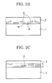
- Figs. 2A to 2C are each a schematic cross-sectional view of the metal particle-containing layer containing the flat metal particles in a heat ray-shielding material of the present invention.
- Fig. 2A illustrates flat metal particles 3 existing in a metal particle-containing layer 2 in an ideal state.
- Fig. 2C illustrates a region where flat metal particles exist in a depth direction of a metal particle-containing layer 2 of the heat ray-shielding material.
- a vertical two-sided arrow in Fig. 2C indicates a region f( ⁇ ) where the particles exist.
- the above-described predetermined angle range of the plane orientation corresponds to angles ( ⁇ ) formed between the surface of the substrate 1 and the main planes of the flat metal particles 3 or extended lines of the main planes, as shown in Fig. 2B . That is, the term "plane orientation" refers to a state where the angles ( ⁇ ) shown in Fig. 2B are small when the cross section of the heat ray-shielding material is observed.
- Fig. 2A illustrates a state where the surface of the substrate 1 is in contact with the main planes of the flat metal particles 3; i.e., the angles ⁇ are 0°.
- the heat ray-shielding material When the main planes of the flat metal particles 3 are plane-oriented on the surface of the substrate 1 at angles exceeding ⁇ 30°; i.e., when the angles ⁇ shown in Fig. 2B exceed ⁇ 30°, the heat ray-shielding material has degraded reflectance to light of a predetermined wavelength (for examples, from a longer wavelength region of the visible light range to the near infrared region) and exhibits large haze, which is not preferred.
- a predetermined wavelength for examples, from a longer wavelength region of the visible light range to the near infrared region
- the method for evaluating whether the main planes of the flat metal particles are plane-oriented on the surface of the substrate is not particularly limited and may be appropriately selected depending on the intended purpose. Examples thereof include a method including preparing appropriate cross-sectional pieces and observing the substrate and the flat metal particles in the pieces.
- the heat ray-shielding material is cut with a microtome or a focused ion beam (FIB) to prepare cross-sectional samples or cross-sectional pieces of the heat ray-shielding material; the thus-prepared samples or pieces are observed with various microscopes (e.g., a field emission scanning electron microscope (FE-SEM)); and the obtained images are used for evaluation.
- FIB focused ion beam
- the cross-sectional samples or cross-sectional pieces may be prepared by freezing the heat ray-shielding material in liquid nitrogen and by cutting the resultant sample with a diamond cutter equipped with a microtome.
- the cross-sectional samples or cross-sectional pieces may be prepared directly.
- the method for observing the above-prepared cross-sectional samples or cross-sectional pieces is not particularly limited and may be appropriately selected depending on the intended purpose, so long as the method can determine whether or not the main planes of the flat metal particles are plane-oriented on the surface of the substrate in the samples.
- the observation can be performed with, for example, a FE-SEM, a TEM and an optical microscope.
- the cross-sectional samples may be observed with a FE-SEM and the cross-sectional pieces may be observed with a TEM.
- the FE-SEM preferably has a spatial resolution with which the shapes of the flat metal particles and the angles ( ⁇ shown in Fig. 2B ) can be clearly observed.
- the metal particle-containing layer 2 preferably exists within a range of ( ⁇ /n)/4 in a depth direction from the horizontal surface of the heat ray-shielding material, where ⁇ , denotes a plasmon resonance wavelength of the metal forming the flat metal particles 3 contained in the metal particle-containing layer 2 and n denotes a refractive index of the medium of the metal particle-containing layer 2.
- the metal particle-containing layer 2 exists in a broader range than this range, the effect of strengthening the phases becomes small at the interfaces between air and the front and rear surfaces of the heat ray-shielding material, potentially leading to a decrease in visible light transmittance and the maximum reflectance to heat rays.
- the plasmon resonance wavelength ⁇ of the metal forming the flat metal particles contained in the metal particle-containing layer is not particularly limited and may be appropriately selected depending on the intended purpose.
- the plasmon resonance wavelength ⁇ is preferably 400 nm to 2,500 nm from the viewpoint of exhibiting heat ray reflectivity. More preferably, the plasmon resonance wavelength ⁇ is 700 nm to 2,500 nm from the viewpoint of reducing haze (scattering) of visible light.
- the medium of the metal particle-containing layer is not particularly limited and may be appropriately selected depending on the intended purpose.
- examples thereof include polyvinylacetal resins, polyvinylalcohol resins, polyvinylbutyral resins, polyacrylate resins, polymethyl methacrylate resins, polycarbonate resins, polyvinyl chloride resins, saturated polyester resins, polyurethane resins, polymers such as naturally occurring polymers (e.g., gelatin and cellulose) and inorganic compounds (e.g. silicon dioxide and aluminum oxide).
- the refractive index n of the medium is preferably 1.4 to 1.7.
- the area ratio of (B/A) ⁇ 100 is preferably 15% or higher, more preferably 20% or higher.
- the area ratio is lower than 15%, the maximum reflectivity to heat rays is decreased, resulting in that satisfactory heat-shielding effects cannot be obtained in some cases.
- the area ratio can be measured, for example, as follows. Specifically, the heat ray-shielding material is observed under a SEM or an AFM (atomic force microscope) and the resultant image is subjected to image processing.
- the average interparticle distance between the flat metal particles neighboring in a horizontal direction is preferably equal to or larger than 1/10 the average particle diameter of the flat metal particles from the viewpoint of obtaining desired visible light transmittance and the maximum reflectance to heat rays.
- the average interparticle distance of the flat metal particles in a horizontal direction is lower than 1/10 the average particle diameter of the flat metal particles, the maximum reflectance to heat rays is disadvantageously decreased.
- the average interparticle distance in a horizontal direction is preferably ununiform (random) from the viewpoint of obtaining visible light transmittance.
- the metal particle-containing layer absorbs visible light, resulting in that its transmittance may be decreased.
- the average interparticle distance of the flat metal particles in a horizontal direction refers to an average value of interparticle distances between two neighboring particles.
- the description "the average interparticle distance is random” means that there is no significant local maximum point except for the origin in a two-dimensional autocorrelation of brightness values when binarizing a SEM image containing 100 or more of flat metal particles.
- the flat metal particles are arranged in the form of the metal particle-containing layer containing the flat metal particles, as shown in Figs. 2A to 2C .
- the metal particle-containing layer may be a single layer as shown in Figs. 2A to 2C . Alternatively, two or more of the metal particle-containing layer may be provided. Provision of two or more of the metal particle-containing layer attains desired shielding of light of a desired wavelength region.
- the production method for the heat ray-shielding material of the present invention is not particularly limited and may be appropriately selected depending on the intended purpose.
- a substrate is coated with a dispersion liquid containing the flat metal particles using, for example, a dip coater, a die coater, a slit coater, a bar coater or a gravure coater.
- the flat metal particles are plane-oriented by, for example, an LB film method, a self-organizing method and a spray method.
- a method utilizing electrostatic interactions may be applied to plane orientation in order to increase adsorbability or plane orientability of the flat metal particles on the substrate surface.
- the substrate surface is positively charged (for example, the substrate surface is modified with an amino group, etc.) to electrostatically enhance plane orientability.
- the substrate surface may be provided with a sea-island structure having hydrophilic and hydrophobic regions using, for example, a block copolymer or a micro contact stamp, to thereby control the plane orientability and the interparticle distance of the flat metal particles utilizing hydrophilic-hydrophobic interactions.
- the coated flat metal particles are allowed to pass through pressure rollers (e.g., calender rollers or rami rollers) to promote their plane orientation.
- pressure rollers e.g., calender rollers or rami rollers
- the solar reflectance of the heat ray-shielding material of the present invention is preferably maximal in the range of 600 nm to 2,000 nm (preferably 700 nm to 1,600 nm) from the viewpoint of increasing efficiency of heat ray reflection.
- the heat ray-shielding material of the present invention preferably has a visible light transmittance of 60% or higher. When the visible light transmittance thereof is lower than 60%, one may difficult to see through automotive glass or building glass using the heat ray-shielding material.
- the heat ray-shielding material of the present invention preferably has a haze of 20% or lower. When the haze thereof exceeds 20%, one may difficult to see through automotive glass or building glass using the heat ray-shielding material, which is not preferred in terms of safety.
- the usage form of the heat ray-shielding material of the present invention is not particularly limited and may be appropriately selected depending on the intended purpose. Examples thereof include vehicles' glass or films, building glass or films and agricultural films. Among them, the heat ray-shielding material is preferably used as vehicles' glass or films and building glass or films in terms of energy saving.
- heat rays refer to near infrared rays (780 nm to 2,500 nm) accounting for about 50% of sunlight.
- the production method for the glass is not particularly limited and may be appropriately selected depending on the intended purpose.
- the heat ray-shielding material produced in the above-described manner is provided with an adhesive layer, and the resultant laminate is attached onto vehicle's glass (e.g., automotive glass) or building glass or is inserted together with a PVB or EVA intermediate film used in laminated glass.
- vehicle's glass e.g., automotive glass
- building glass e.g., building glass
- a PVB or EVA intermediate film used in laminated glass e.g., a PVB or EVA intermediate film used in laminated glass.
- only particle/binder layer may be transferred onto a PVB or EVA intermediate film; i.e., the substrate may be peeled off in use.
- the silver interaction potential EAg of the heterocyclic ring compounds used in Examples and Comparative Examples was measured as follows.
- the silver interaction potential EAg can be measured by the following silver interaction potential method.
- a solution 50 mL containing a heterocyclic ring compound at a concentration of 0.00100 M, potassium bicarbonate at a concentration of 0.0200 M and potassium carbonate at a concentration of 0.0267 M.
- the pH of the prepared solution is adjusted to 10.0 with 1 M nitric acid or sodium hydroxide.
- 1 mL of 0.00500 M silver nitrate was added to the resultant solution at 20°C to 25°C with magnetic stirring.
- the potential of the solution 15 min after the addition of the silver nitrate was measured by an electrochemical method using a calomel electrode.
- the potential (mV) thusly measured is a silver interaction potential.
- a 0.5 g/L aqueous polystyrenesulfonic acid solution (2.5 mL) was added to a 2.5 mM aqueous sodium citrate solution (50 mL), followed by heating to 35°C. Then, a 10 mM sodium borohydride solution (3 mL) was added to the resultant solution. Next, a 0.5 mM aqueous silver nitrate solution (50 mL) was added thereto at 20 mL/min under stirring. This solution was stirred for 30 min to prepare a seed particle solution (the synthesis step of flat nuclear particles).
- ion-exchanged water 87.1 mL was added to a 2.5 mM aqueous sodium citrate solution (132.7 mL), followed by heating to 35°C.
- a 10 mM aqueous ascorbic acid solution (2 mL) was added to the resultant solution and then 42.4 mL of the above-prepared seed particle solution was added thereto.
- a 0.5 mM aqueous silver nitrate solution (79.6 mL) was added thereto at 10 mL/min under stirring (the first growth step of flat particles).
- the above-obtained solution was stirred for 30 min, and then a 0.35 M aqueous potassium hydroquinonesulfonate solution (71.1 mL) was added thereto. Further, 200 g of a 7% by mass aqueous gelatin solution was added thereto. Separately, 0.25 M aqueous sodium sulfite solution (107 mL) and a 0.47 M aqueous silver nitrate solution (107 mL) were mixed together to prepare a mixture containing white precipitates. The thus-prepared mixture was added to the solution to which the aqueous gelatin solution had been added.
- a 0.17 M aqueous NaOH solution 72 mL was added to the resultant mixture.
- the aqueous NaOH solution was added thereto at an addition rate adjusted so that the pH of the mixture did not exceed 10.
- the thus-obtained mixture was stirred for 300 min to prepare a dispersion liquid of flat silver particles (the second growth step of flat particles).
- the obtained flat silver particle dispersion liquid was found to contain hexagonal flat silver particles. Also, the obtained flat silver particles were measured for various properties as follows. The results are shown in Table 1.
- silver nanorods were produced.
- the produced silver nanorods were found to have a major axis of 250 nm, a minor axis of 42 nm and an aspect ratio (major axis/minor axis) of 6.
- the average particle diameter of the flat silver particles was obtained as follows. Specifically, 200 particles were randomly selected from the SEM image observed. Then, image processing was performed on their shapes, with A and B corresponding respectively to substantially hexagonal or disc-like particles and amorphous particles (e.g., drop-like particles). Subsequently, particles corresponding to A were measured for equivalent circle diameter with a digital caliper. The average value of the equivalent circle diameters was defined as an average particle diameter. Moreover, the standard deviation of the equivalent circle diameters was divided by the average particle diameter to obtain variation coefficient (%).
- the dispersion liquid containing flat silver particles was dropped on a glass substrate, followed by drying. Then, the thickness of each flat silver particle was measured with an atomic force microscope (AFM) (Nanocute II, product of Seiko Instruments Inc.). Notably, the measurement conditions of AFM were as follows: self-detection sensor, DFM mode, measurement range: 5 ⁇ m, scanning speed: 180 sec/frame and the number of data: 256 ⁇ 256.
- AFM atomic force microscope
- the average particle diameter was divided by the average particle thickness to obtain an aspect ratio of the obtained flat silver particles (average particle diameter/average particle thickness).
- Table 1 Shape Ratio of flat metal particles (or rods) (% by number) Average particle diameter (nm) Average particle thickness (nm) Aspect ratio Variation coefficient of particle size distribution (%) Production Example 1 Substantially hexagonal 84 230 16 14.3 28 Production Example 2 Rod 93 (250) (42) (6) 17 *In the rods in Table 1, the average particle diameter is the major axis thereof, the average particle thickness is the minor axis thereof, and the aspect ratio is a value obtained by dividing the average particle diameter with the average particle thickness
- the hexagonal flat silver particles were fixed on the PET film without aggregation. Through the above procedure, a heat ray-shielding material of sample No. 104 was produced.
- sample No. 104 The procedure of sample No. 104 was repeated, except that the flat silver particle dispersion liquid of Production Example 1 was changed to the silver nanorod dispersion of Production Example 2, to thereby produce a heat ray-shielding material of sample No. 101.
- sample No. 101 The procedure of sample No. 101 was repeated, except that Compound at-12 having the following structural formula was added in an amount of 3.0 ⁇ 10 -3 mole relative to 1 mole of silver contained in the silver nanorod dispersion of Production Example 2, to thereby produce a heat ray-shielding material of sample No. 103.
- sample No. 104 The procedure of sample No. 104 was repeated, except that Compound at-12 having the above structural formula was added in an amount of 3.0 ⁇ 10 -3 mole relative to 1 mole of silver contained in the flat silver particle dispersion of Production Example 1, to thereby produce a heat ray-shielding material of sample No. 107.
- sample No. 104 The procedure of sample No. 104 was repeated, except that Compound at-20 having the following structural formula was added in an amount of 3.0 ⁇ 10 -3 mole relative to 1 mole of silver contained in the flat silver particle dispersion of Production Example 1, to thereby produce a heat ray-shielding material of sample No. 108.
- sample No. 104 The procedure of sample No. 104 was repeated, except that Compound at-21 having the following structural formula was added in an amount of 3.0 ⁇ 10 -3 mole relative to 1 mole of silver contained in the flat silver particle dispersion of Production Example 1, to thereby produce a heat ray-shielding material of sample No. 109.
- sample No. 104 The procedure of sample No. 104 was repeated, except that Compound at-11 having the following structural formula was added in an amount of 3.0 ⁇ 10 -3 mole relative to 1 mole of silver contained in the flat silver particle dispersion of Production Example 1, to thereby produce a heat ray-shielding material of sample No. 110.
- sample No. 104 The procedure of sample No. 104 was repeated, except that Compound at-19 having the following structural formula was added in an amount of 3.0 ⁇ 10 -3 mole relative to 1 mole of silver contained in the flat silver particle dispersion of Production Example 1, to thereby produce a heat ray-shielding material of sample No. 111.
- Each of the produced heat ray-shielding materials was measured for transmission spectrum and reflection spectrum according to the JIS evaluation standard for automotive glass.
- the transmission and reflection spectra were evaluated with a UV-Vis near infrared spectrophotometer (product of JASCO Corporation, V-670). The evaluation was performed using an absolute reflectance measurement unit (ARV-474, product of JASCO Corporation). Here, incident light was caused to pass through a 45° polarization plate so as to become substantially non-polarized light.
- UV-Vis near infrared spectrophotometer product of JASCO Corporation, V-670
- ARV-474 product of JASCO Corporation
- the heat ray maximum reflectance was measured according to the method of JIS-R3106: 1998 "Testing method on transmittance, reflectance and emittance of flat glasses and evaluation of solar heat gain coefficient. " After initial measurement ranging from 300 nm to 2,100 nm, the maximum reflectance was defined as the infrared ray maximum reflectance. Specifically, using SUPER XENON WEATHER METER SX-75 (product of Suga Test Instruments Co., Ltd.), each heat ray-shielding material was irradiated with xenon light for 4 weeks under the conditions: 180 W/m 2 , black panel temperature: 63°C and humidity: 25%RH, and then the maximum reflectance of the material was defined as the infrared ray maximum reflectance.
- the visible light transmittance was measured as follows. Each heat ray-shielding material was measured for transmittance with respect to each wavelength ranging from 380 nm to 780 nm, and the thus-measured transmittances were corrected with the luminosity factor of each wavelength.
- Each of the obtained heat ray-shielding materials was observed under a scanning electron microscope (SEM).
- SEM scanning electron microscope
- the obtained SEM image was binarized to determine an area ratio of (B/A) ⁇ 100, where A and B denote respectively a projected area of the substrate and the total value of projected areas of the flat metal particles when the heat ray-shielding material is viewed from a perpendicular direction.
- Each of the obtained heat ray-shielding materials was embedded in an epoxy resin, followed by freezing in liquid nitrogen. In this state, the freezed product was cut with a razor to prepare a vertically cross-sectional sample of the heat ray-shielding material. The thus-prepared vertically cross-sectional sample was observed under a scanning electron microscope (SEM). Then, 100 flat metal particles were examined for tilt angle with respect to the horizontal surface of the substrate, to calculate the average tilt angle of the flat metal particles.
- SEM scanning electron microscope
- each heat ray-shielding material was measured for haze value (%).
- Table 2-1 Sample No. Particle Heterocyclic ring compound Visible light (550nm) Initial After Xe irradiation Infrared light (800mn to 2000nm) Infrared light (800nm to 2000nm) Compd. EAg (mV) Amount (mol) Transmittance (%) Max. reflectance (%) Max. absorbance (%) Max. reflectance (%) Max. absorbance (%) Max. absorbance (%) 101 Rod - - - 85 7 43 7 42 Comp. Ex. 102 Rod Comp. Compd.
- the heat ray-shielding materials of the present invention were found to exhibit a higher infrared reflectance than those of the heat ray-shielding materials of Comparative Examples.
- the heat ray-shielding materials of the present invention did not decrease in infrared reflectance after irradiation of Xe light than did the heat ray-shielding materials of Comparative Examples.
- the flat metal particles exist more stably and reduction of plasmon reflection due to light can be prevented.
- the flat metal particle-containing composition can be suitably used in, for example, a heat ray reflection film, an infrared ray reflection film, a visible light reflection film, a heat ray absorption film, an infrared ray absorption film and a selective reflection film.
- the heat ray-shielding material of the present invention has high selectivity for reflection wavelength or region, has excellent transmittance with respect to visible light and radio wave and has excellent light resistance, and thus, can be suitably used as various members required for shielding heat rays, such as glass of vehicles (e.g., automobiles and buses), building glass and agricultural films.
Landscapes
- Engineering & Computer Science (AREA)
- Chemical & Material Sciences (AREA)
- Nanotechnology (AREA)
- General Physics & Mathematics (AREA)
- Crystallography & Structural Chemistry (AREA)
- Physics & Mathematics (AREA)
- Composite Materials (AREA)
- Condensed Matter Physics & Semiconductors (AREA)
- Dispersion Chemistry (AREA)
- Materials Engineering (AREA)
- Inorganic Chemistry (AREA)
- Laminated Bodies (AREA)
- Powder Metallurgy (AREA)
- Optical Filters (AREA)
- Manufacture Of Metal Powder And Suspensions Thereof (AREA)
- Optical Elements Other Than Lenses (AREA)
- Paints Or Removers (AREA)
Abstract
Description
- The present invention relates to a flat metal particle-containing composition suitable to, for example, a heat ray reflection films, an infrared ray reflection film, a visible light reflection films, a heat ray absorption films, an infrared ray absorption film and a selective reflection film and to a heat ray-shielding material selectively reflecting and absorbing heat rays.
- Nanoparticles have a size smaller than wavelengths of light and thus attract attention as a material with low light scattering. Among others, research has been made on metal nanoparticles in various fields, since they have electrical conductivity, thermal conductivity, favorable refractive index, catalytic activity, and other features.
- The metal nanoparticles have a large surface area and often pose problematic corrosion and migration. For example,
U.S. Pat. Application Publication No. 2007/0074316 discloses that an aromatic triazole compound and the like are advantageous as a corrosion inhibitor for Ag nanowires. - Also, Japanese Patent Application Laid-Open (JP-A) No.
2009-146678 - These prior art documents present solutions against migration or corrosion causing insulation when Ag is used as a conductive material. However, they neither disclose nor suggest stability relating to light resistance as seen in the present invention.
- Moreover, Japanese Patent (JP-B) No.
3594803 JP-B No. 3594803 - Therefore, at present, demand has arisen for provision of a flat metal particle-containing composition in which flat metal particles exist more stably and reduction of plasmon reflection due to light can be prevented; and a heat ray-shielding material which has high selectivity for reflection wavelength or region, has excellent transmittance with respect to visible light and radio wave, and has excellent light resistance.
- The present invention aims to provide a flat metal particle-containing composition in which flat metal particles exist more stably and reduction of plasmon reflection due to light can be prevented and which can be suitably used in, for example, a heat ray reflection film, an infrared ray reflection film, a visible light reflection film, a heat ray absorption film, an infrared ray absorption film and a selective reflection film; and a heat ray-shielding material which has high selectivity for reflection wavelength or region, has excellent transmittance with respect to visible light and radio wave, and has excellent light resistance.
- The present inventors conducted studies on a reflection film utilizing plasmon reflection in order to solve the above existing problems, and have found that nanosized noble metal particles (including flat metal nanoparticles) are degraded in light resistance. One possible reason for degradation of the noble metal nanoparticles in light resistance lies in the reduction of stability due to increasing of surface energy with increasing specific surface areas. In this case, it is difficult to protect the noble metal by adding a large amount of a resin to the composition. Thus, the present inventors conducted extensive studies, and as a result have found that by incorporating into flat metal particles a heterocyclic ring compound having a silver interaction potential EAg of -1 mV or lower, stability of flat metal particles is increased, reduction of plasmon reflection due to light can be prevented, and better light resistance can be attained.
- The present invention is based on the above finding obtained by the present inventors. Means for solving the above problems are as follows.
- <1> A flat metal particle-containing composition including:
- flat metal particles, and
- a heterocyclic ring compound,
- wherein the heterocyclic ring compound has a silver interaction potential EAg which is lower than -1 mV
- <2> The flat metal particle-containing composition according to <1>, wherein the silver interaction potential EAg of the heterocyclic ring compound is -300 mV or higher but lower than -1 mV.
- <3> The flat metal particle-containing composition according to <1> or <2>, wherein the flat metal particles contain silver, gold, copper or an alloy thereof.
- <4> The flat metal particle-containing composition according to any one of <1> to <3>, wherein the flat metal particles contain silver.
- <5> A heat ray-reflection film including:
- the flat metal particle-containing composition according to any one of <1> to <4>.
- <6> An infrared ray-reflection film including:
- the flat metal particle-containing composition according to any one of <1> to <4>.
- <7> A heat ray-absorption film including:
- the flat metal particle-containing composition according to any one of <1> to <4>.
- <8> An infrared ray-absorption film including:
- the flat metal particle-containing composition according to any one of <1> to <4>.
- <9> A selective reflection film including:
- the flat metal particle-containing composition according to any one of <1> to <4>.
- <10> A heat ray-shielding material including:
- the flat metal particle-containing composition according to any one of <1> to <4>.
- <11> The heat ray-shielding material according to <10>, further including a substrate and a flat metal particle-containing layer on the substrate, wherein the flat metal particle-containing layer is formed of the flat metal particle-containing composition, and main planes of the flat metal particles are plane-oriented at 0° to ±30° with respect to a surface of the substrate.
- <12> The heat ray-shielding material according to <11>, wherein the heat ray-shielding material has an area ratio of 15% or higher, the area ratio being calculated by B/A × 100, where A and B denote a projected area of the substrate and a total value of projected areas of the flat metal particles, respectively, when the heat ray-shielding material is viewed from a perpendicular direction.
- The present invention can provide a flat metal particle-containing composition in which flat metal particles exist more stably and reduction of plasmon reflection due to light can be prevented and which can be suitably used in, for example, a heat ray reflection film, an infrared ray reflection films, a visible light reflection film, a heat ray absorption film, an infrared ray absorption film and a selective reflection film; and a heat ray-shielding material which has high selectivity for reflection wavelength or region, has excellent transmittance with respect to visible light and radio wave, and has excellent light resistance.
-
-
Fig. 1A is a schematic perspective view of a disc-like flat particle which is one exemplary flat metal particle. -
Fig. 1B is a schematic perspective view of a substantially hexagonal flat particle which is one exemplary flat metal particle. -
Fig. 2A is a schematic cross-sectional view of a metal particle-containing layer containing flat metal particles in a heat ray-shielding material of the present invention, where the flat metal particles exist in an ideal state. -
Fig. 2B is a schematic cross-sectional view of a metal particle-containing layer containing flat metal particles in a heat ray-shielding material of the present invention, which is for explaining angles (θ) formed between a surface of a substrate and planes of flat particles -
Fig. 2C is a schematic cross-sectional view of a metal particle-containing layer containing flat metal particles in a heat ray-shielding material of the present invention, which illustrates a region where the flat metal particles exist in a depth direction of the metal particle-containing layer of the heat ray-shielding material. - A flat metal particle-containing composition of the present invention includes at least flat metal particles and a heterocyclic ring compound having a silver interaction potential EAg lower than -1 mV; and, if necessary, further includes other components.
- In general, nanoparticles are classified into 0-dimensional particles (substantially spherical), 1-dimensional particles (substantially rod), 2-dimensional particles (substantially flat) and 3-dimensional particles (bulk). The flat particles belong to the 2-dimensional substantially flat particles. Considering plasmon reflection, among the flat particles, preferred are flat triangular particles, flat hexagonal particles, and disc-like particles (i.e., flat triangular or hexagonal particles whose corners have been rounded).
- Also, flat particles must be used for obtaining reflectivity. When 0-dimensional particles, 1-dimensional particles or 3-dimensional particles are planarily arranged, plasmon absorption is merely observed depending on each shape, so that satisfactory reflectivity cannot be obtained. Only when 2-dimensional particles are planarily arranged, one can obtain reflectivity which is a feature of the present invention.
- The flat metal particles are not particularly limited, so long as they are particles having two main planes (see
Figs. 1A and 1B ), and may be appropriately selected depending on the intended purpose. Examples thereof include substantially hexagonal particles, disc-like particles and substantially triangular particles. Among them, particularly preferred are substantially hexagonal particles and disc-like particles, since they have high transmittance with respect to visible light. Notably, in each ofFigs. 1A and 1B , a horizontal two-sided arrow indicates a diameter and a vertical two-sided arrow indicates a thickness. - The disc-like particles are not particularly limited and may be appropriately selected depending on the intended purpose, so long as they have round corners when observed from a perpendicular direction of their main plane under a transmission electron microscope (TEM).
- The substantially hexagonal particles are not particularly limited and may be appropriately selected depending on the intended purpose, so long as they have a substantially hexagonal shape when observed from a perpendicular direction of their main plane under a transmission electron microscope (TEM). For example, the corners of the hexagonal shape may be sharp or dull. From the viewpoint of reducing absorption of visible light, the corners thereof are preferably dull. The extent to which the corners are dull is not particularly limited and may be appropriately selected depending on the intended purpose.
- The material for the flat metal particles is not particularly limited and may be appropriately selected depending on the intended purpose. Examples thereof include silver, gold, copper and alloys thereof. Among them, silver is particularly preferred, since it has high reflectivity with respect to heat rays (near infrared rays) and has no absorption of visible light.
- The ratio of the substantially hexagonal particles or disc-like particles is preferably 60% by number or higher, more preferably 65% by number or higher, further preferably 70% by number or higher, relative to the total number of the metal particles. When the ratio of the above flat metal particles is lower than 60% by number, transmittance with respect to visible light rays may be decreased, which is disadvantageous.
- The average particle diameter of the flat metal particles is not particularly limited and may be appropriately selected depending on the intended purpose. It is preferably 70 nm to 500 nm, more preferably 100 nm to 400 nm. When the average particle diameter thereof is less than 70 nm, the flat metal particles exhibit high absorbance to exhibit low reflectivity, resulting in that satisfactory heat ray reflectivity cannot be obtained in some cases. When the average particle diameter thereof exceeds 500 nm, haze (scattering) becomes large, resulting in that transparency of a substrate may be degraded.
- Here, the average particle diameter refers to an average value of main planes' diameters (the maximum lengths) of 200 flat particles randomly selected from an image obtained through observation of particles under a TEM.
- The metal particle-containing layer may contain two or more kinds of metal particles having different average particle diameters. In this case, the metal particles may have two or more peaks of average particle diameter; i.e., may have two average particle diameters.
- In the heat ray-shielding material of the present invention, variation coefficient in a particle size distribution of the flat metal particles is preferably 30% or lower, more preferably 10% or lower. When the variation coefficient exceeds 30%, the wavelength region of heat rays reflected by the heat ray-shielding material may become broad, which is disadvantageous.
- Here, the variation coefficient in the particle size distribution of the flat metal particles refers to a value (%) obtained as follows. Specifically, the particle diameters of the 200 flat metal particles, which are selected for determining the average particle diameter as described above, are plotted to obtain their distribution range. Then, the standard deviation of the particle size distribution is calculated and divided by the above-obtained average particle diameter of the main planes' diameters (the maximum lengths).
- The aspect ratio of the flat metal particles is not particularly limited and may be appropriately selected depending on the intended purpose. The aspect ratio thereof is preferably 2 or higher, more preferably 2 to 80, further preferably 4 to 60, since high reflectivity can be obtained from a longer wavelength region of the visible light range to the near infrared region. When the aspect ratio is less than 2, reflectivity may become low or haze may become large.
- The aspect ratio refers to value L/d, where L denotes an average particle diameter of flat metal particles and d denotes an average particle thickness of flat metal particles. The average particle thickness corresponds to the interdistance of the main planes of flat metal particles as shown in, for example,
Figs. 1A and 1B , and can be measured with an atomic force microscope (AFM). - The measurement method of the average particle thickness with the AFM is not particularly limited and may be appropriately selected depending on the intended purpose. For example, a particle dispersion liquid containing flat metal particles is dropped on a glass substrate, followed by drying, to thereby measure the thickness of each particle.
- The synthesis method for the flat metal particles is not particularly limited, so long as substantially hexagonal or disc-like particles can be synthesized, and may be appropriately selected depending on the intended purpose. Examples thereof include liquid phase methods such as chemical reduction methods, photochemical reduction methods and electrochemical reduction methods. Among these liquid phase methods, particularly preferred are chemical reduction methods and photochemical reduction methods from the viewpoint of controlling shape and size. Furthermore, after hexagonal or triangular flat metal particles have been synthesized, they may be subjected to, for example, an etching treatment using chemical species that dissolve silver (e.g., nitric acid, sodium sulfite and halogen ions such as Br- and Cl-) or an aging treatment with heating so as to round the corners of the hexagonal or triangular flat metal particles, whereby substantially hexagonal or disc-like flat metal particles may be produced.
- In an alternative synthesis method of the flat metal particles, seed crystals are fixed in advance on a surface of a transparent substrate (e.g., a film or a glass) and then are planarily grown to form metal particles (e.g., Ag).
- In the heat ray-shielding material of the present invention, flat metal particles may be subjected to a further treatment in order for the flat metal particles to have desired properties. The further treatment is not particularly limited and may be appropriately selected depending on the intended purpose. Examples thereof include formation of a high-refractive-index shell layer and addition of various additives such as a dispersant and an anti-oxidant).
- The flat metal particles may be coated with a high-refractive-index material having high transparency with respect to visible light so as to further increase transparency with respect to visible light. Alternatively, a high-refractive-index material layer is provided at the upper or lower portion of the flat metal particle-containing layer in the present invention, preferably at the both upper and lower portions.
- The high-refractive-index material is not particularly limited and may be appropriately selected depending on the intended purpose. Examples thereof include TiOx, BaTiO3, ZnO, SnO2, ZrO2 and NbOx.
- The coating method of the high-refractive-index material is not particularly limited and may be appropriately selected depending on the intended purpose. Examples thereof include a method in which a TiOx layer is formed on flat silver particles by hydrolyzing tetrabutoxytitanium as described in Langmuir, 2000, Vol. 16, pp. 2731-2735.
- When it is difficult to directly form the high-refractive-index shell layer (metal oxide layer) on the flat metal particles, a SiO2 or polymer shell layer may be formed on each particle in advance and the metal oxide layer may be formed on the thus-formed shell layer. When TiOx is used as a material for the high-refractive-index metal oxide layer, there is concern that TiOx degrades a matrix in which flat metal particles are dispersed, since TiOx exhibits photocatalytic activity Thus, depending on the intended purpose, a SiO2 layer may be appropriately formed after formation of a TiOx on each flat metal particle.
- In the flat metal particle-containing composition of the present invention, an anti-oxidant (e.g., mercaptotetrazole or ascorbic acid) may be adsorbed onto the flat metal particles so as to prevent oxidation of the metal (e.g., silver) forming the flat metal particles. Also, an oxidation sacrificial layer (e.g., Ni) may be formed on the flat metal particles for preventing oxidation. Furthermore, the flat metal particles may be coated with a metal oxide film (e.g., SiO2 film) for shielding oxygen.
- Also, a dispersing agent may be used for imparting dispersibility to the flat metal particles. Examples of the dispersing agent include high-molecular-weight dispersing agents and low-molecular-weight dispersing agents containing N, S and/or P such as quaternary ammonium salts and amines.
- The heterocyclic ring compound must have a silver interaction potential EAg which is lower tan -1 mV, preferably -300 mV or higher but lower than -1 mV, more preferably -70 mV to -300 mV.
- When the silver interaction potential EAg thereof is -1 mV or higher, light resistance cannot be obtained in some cases. When the silver interaction potential EAg thereof is lower than -300 mV, the obtained effects become low, which is disadvantageous.
- Here, the silver interaction potential EAg can be measured by the following silver interaction potential method.
- First, there is prepared a solution (50 mL) containing a heterocyclic ring compound at a concentration of 0.00100 M, potassium bicarbonate at a concentration of 0.0200 M and potassium carbonate at a concentration of 0.0267 M. The pH of the prepared solution is adjusted to 10.0 with 1 M nitric acid or sodium hydroxide. Then, 1 mL of 0.00500 M silver nitrate is added to the resultant solution at 20°C to 25°C with magnetic stirring. The potential of the solution 15 min after the addition of the silver nitrate is measured by an electrochemical method using a calomel electrode. The potential (mV) thusly measured is a silver interaction potential.
- Here, the heterocyclic ring compound refers to a ring compound having one or more hetero atoms. The hetero atom refers to other atoms than a carbon atom and a hydrogen atom. No limitation is imposed on the number of hetero atoms the heterocyclic ring compound has. Notably, the hetero atom refers to an atom forming the heterocyclic ring of the heterocyclic ring compound, not refers to an atom which located outside the ring, which is separated from the ring via at least one unconjugated single bond, or which is part of the substituent of the ring.
- Preferred examples of the hetero atom include a nitrogen atom, a sulfur atom, an oxygen atom, a selenium atom, a tellurium atom, a phosphorus atom, a silicon atom and a boron atom, with a nitrogen atom, a sulfur atom, an oxygen atom and a selenium atom being more preferred, with a nitrogen atom, a sulfur atom and an oxygen atom being further preferred, with a nitrogen atom and a sulfur atom being particularly preferred.
- The number of the atoms forming the heterocyclic ring of the heterocyclic ring compound may be any number, but the heterocyclic ring is preferably a 3- to 8-membered ring, further preferably a 5- to 7-membered ring, particularly preferably a 5- or 6-membered ring.
- The heterocyclic ring may be saturated or unsaturated. The heterocyclic ring is preferably has at least one unsaturated bond, further preferably has at least two unsaturated bonds. In other words, the heterocyclic ring may be any of an aromatic ring, a pseudoaromatic ring and a nonaromatic ring. The heterocyclic ring is preferably an aromatic heterocyclic ring or a pseudoaromatic heterocyclic ring, further preferably an aromatic heterocyclic ring.
- Examples of the heterocyclic ring include a pyrrole ring, a thiophene ring, a furan ring, an imidazole ring, a pyrazole ring, a thiazole ring, an isothiazole ring, an oxazole ring, an isooxazole ring, a 1,2,4-triazole ring, a 1,2,3-triazole ring, a tetrazole ring, a 1,2,5-thiadiazole ring, a 1,3,4-thiadiazole ring, a 1,2,3,4-thiatriazole ring, a pyridine ring, a pyrazine ring, a pyrimidine ring, a pyridazine ring, an indolizine ring, benzocondensed compounds thereof, an indole ring, a benzofuran ring, a benzothiophen ring, an isobenzofuran ring, a benzimidazole ring, a benzotriazole ring, a benzothiadiazole ring, a benzoxadiazole ring, a quinolidine ring, a quinoline ring, a phthalazine ring, a quinoxaline ring, an isoquinoline ring, a carbazole ring, a phenanthridine ring, a phenanthroline ring, an acridine ring, a purine ring, a 4,4'-bipyridine ring, a 1,2-bis(4-pyridyl)ethan ring, a 4,4'-trimethylenedipyridine ring, partially or totally saturated compounds thereof, a pyrrolidine ring, a pyrroline ring and an imidazoline ring.
- Some typical heterocyclic rings are as follows.


- Some exemplary heterocyclic rings fused with a benzene ring are as follows.


- Some exemplary heterocyclic rings partially or totally saturated are as follows.


- In addition, the following heterocyclic rings can be used.


- These heterocyclic rings may be substituted or fused with any substituent, and examples of the substituent include the below-described W. Also, a tertiary nitrogen atom contained in the heterocyclic ring may have a further substituent to be a quaternary nitrogen atom. Notably, the heterocyclic rings are chemically equivalent to their tautomers, if any.
- Among the above heterocyclic rings, those indicated by (aa-1), (aa-3), (aa-19), (aa-20), (ab-12) and (ab-25) are particularly preferred.
- When a specific part in the heterocyclic ring compound is referred to as a "group," this part may be unsubstituted or substituted by one or more substituents whose maximum number depends on the part. For example, the "alkyl group" refers to a substituted or unsubstituted alkyl group. The substituent usable in the heterocyclic ring compound may be any substituent which may have a substituent.
- When such a substituent is denoted by W, the substituent W is any substituent without any limitation. Examples thereof include a halogen atom, an alkyl group (including a cycloalkyl group, a bicycloalkyl group and a tricycloalkyl group), an alkenyl group (including a cycloalkenyl group and a bicycloalkenyl group), an alkynyl group, an aryl group, a heterocyclic ring group (or a heterocyclic group), a cyano group, a hydroxyl group, a nitro group, a carboxyl group, an alkoxy group, an aryloxy group, a silyloxy group, a heterocyclic oxy group, an acyloxyl group, a carbamoyloxy group, an alkoxycarbonyloxy group, an aryloxycarbonyloxy group, an amino group (including an alkylamino group, an arylamino group and a heterocyclic amino group), an ammonio group, an acylamino group, an aminocarbonylamino group, an alkoxycarbonylamino group, an aryloxycarbonylamino group, a sulfamoylamino group, an alkyl or arylsulfonylamino group, a mercapto group, an alkylthio group, an arylthio group, a heterocyclicthio group, a sulfamoyl group, a sulfo group, an alkyl or arylsulfinyl group, an alkyl or arylsulfonyl group, an acyl group, an aryloxycarbonyl group, an alkoxycarbonyl group, a carbamoyl group, an aryl or heterocyclicazo group, an imide group, a phosphino group, a phosphinyl group, a phosphinyloxy group, a phosphinylamino group, a phosphono group, a silyl group, a hydrazino group, an ureido group, a boronic acid group (-B(OH)2), a phosphato group (-OPO(OH)2), sulphato group (-OSO3H) and other known substituents.
- More specifically, the substituent W is a halogen atom such as a fluorine atom, a chlorine atom, a bromine atom or an iodine atom; or a linear, branched or cyclic, substituted or unsubstituted alkyl group. Such an alkyl group includes alkyl groups (preferably C1-C30 alkyl groups such as methyl, ethyl, n-propyl, isopropyl, t-butyl, n-octyl, eicosyl, 2-chloroethyl, 2-cyanoethyl and 2-ethylhexyl), cycloalkyl groups (preferably C3-C30 substituted or unsubstituted cycloalkyl groups such as cyclohexyl, cyclopentyl and 4-n-dodecylcyclohexyl) and bicycloalkyl groups (preferably C5-C30 substituted or unsubstituted bicycloalkyl groups; i.e., monovalent groups obtained by removing one hydrogen atom from C5-C30 bicycloalkanes, such as bicyclo[1,2,2]heptan-2-yl and bicyclo[2,2,2]octan-3-yl); and also includes multiple ring structures such as tricyclo structures. The alkyl group of the below-described substituents (for example, the alkyl group of an alkylthio group) is the above-described alkyl group but further includes an alkenyl group and an alkynyl group, herein. The alkenyl group is linear, branched or cyclic, substituted or unsubstituted alkenyl groups. The substituent W includes alkenyl groups (preferably C2-C30 substituted or unsubstituted alkenyl groups such as vinyl, allyl, prenyl, geranyl and oleyl), cycloalkenyl groups (preferably C3-C30 substituted or unsubstituted cycloalkenyl groups; i.e., monovalent groups obtained by removing one hydrogen atom from C3-C30 cycloalkenes, such as 2-cyclopenten-1-yl and 2-cyclohexen-1-yl), bicycloalkenyl groups (substituted or unsubstituted bicycloalkenyl groups, preferably C5-C30 substituted or unsubstituted bicycloalkenyl groups; i.e., monovalent groups obtained by removing one hydrogen atom from bicycloalkenes having one double bond, such as bicyclo[2,2,1]hept-2-en-1-yl and bicyclo[2,2,2]oct-2-en-4-yl); alkynyl groups (preferably, C2-C30 substituted or unsubstituted alkynyl groups such as ethynyl, propargyl and trimethylsilylethynyl), aryl groups (preferably C6-C30 substituted or unsubstituted aryl groups such as phenyl, p-tolyl, naphthyl, m-chlorophenyl and o-hexadecanoylaminophenyl), heterocyclic ring groups (preferably monovalent groups which may be fused with a benzene ring, etc. and which are obtained by removing one hydrogen atom from 5- or 6-membered substituted or unsubstituted, aromatic or nonarmoatic heterocyclic ring compound, further preferably 5- or 6-membered C3-C30 aromatic heterocyclic ring groups such as 2-furyl, 2-thienyl, 2-pyrimidinyl and 2-benzothiazolyl (note that the heterocyclic ring groups may be cationic heterocyclic ring groups such as 1-methyl-2-pyridinio and 1-methyl-2-quinolynio)), a cyano group, a hydroxyl group, a nitro group, a carboxyl group, an alkoxy group (preferably C1-C30 substituted or unsubstituted alkoxy groups such as methoxy, ethoxy, isopropoxy, t-butoxy, n-octyloxy and 2-methoxyethoxy), aryloxy groups (preferably C6-C30 substituted or unsubstituted aryloxy groups such as phenoxy, 2-methylphenoxy, 4-t-butylphenoxy, 3-nitrophenoxy and 2-tetradecanoylaminophenoxy), silyloxy groups (preferably C3-C20 silyloxy groups such as trimethylsilyloxy and t-butyldimethylsilyloxy), heterocyclic oxy groups (preferably C2-C30 substituted or unsubstituted heterocyclic oxy groups such as 1-phenyltetrazole-5-oxy and 2-tetrahydropyranyloxy), acyloxyl groups (preferably a formyloxy group, C2-C30 substituted or unsubstituted alkylcarbonyloxy groups, C7-C30 substituted or unsubstituted arylcarbonyloxy groups such as formyloxy, acetyloxy, pivaloyloxy, stealoyloxy, benzoyloxy and p-methoxyphenylcarbonyloxy), carbamoyloxy groups (preferably C1-C30 substituted or unsubstituted carbamoyloxy groups such as N,N-dimethylcarbamoyloxy, N,N-diethylcarbamoyloxy, morpholinocarbonyloxy, N,N-di-n-octylaminocarbonyloxy and N-n-octylcarbamoyloxy), alkoxycarbonyloxy groups (preferably C2-C30 substituted or unsubstituted alkoxycarbonyloxy groups such as methoxycarbonyloxy, ethoxycarbonyloxy, t-butoxycarbonyloxy and n-octylcarbonyloxy), aryloxycarbonyloxy groups (preferably C7-C30 substituted or unsubstituted aryloxycarbonyloxy groups such as phenoxycarbonyloxy, p-methoxyphenaxycarbonyloxy and p-n-hexadecyloxyphenoxycarbonyloxy), amino groups (preferably an amino group, C1-C30 substituted or unsubstituted alkylamino groups, C6-C30 substituted or unsubstituted arylamino groups, heterocyclic amino groups, such as amino, methylamino, dimethylamino, anilino, N-methyl-anilino, diphenylamino and 2-pyridylamino), ammonio groups (preferably an ammonio group; ammonio groups substituted with C1-C30 substituted or unsubstituted alkyls, aryls or heterocyclic ring, such as trimethylammonio, triethylammonio and diphenylmethylammonio), acylamino groups (preferably a formylamino group, C1-C30 substituted or unsubstituted alkylcarbonylamino groups and C6-C30 substituted or unsubstituted arylcarbonylamino groups, such as formylamino, acetylamino, pivaloylamino, lauroylamino, benzoylamino and 3,4,5-tri-n-octyloxyphenylcarbonylamino), aminocarbonylamino groups (preferably C1-C30 substituted or unsubstituted aminocarbonylaminos such as carbamoylamino, N,N-dimethylaminocarbonylamino, N,N-diethylaminocarbonylamino and morpholinocarbonylamino), alkoxycarbonylamino groups (preferably C2-C30 substituted or unsubstituted alkoxycarbonylamino groups such as methoxycarbonylamino, ethoxycarbonylamino, t-butoxycarbonylamino, n-octadecyloxycarbonylamino and N-methyl-methoxycarbonylamino), aryloxycarbonylamino groups (preferably C7-C30 substituted or unsubstituted aryloxycarbonylamino groups such as phenoxycarbonylamino, p-chlorophenoxycarbonylamino and m-n-octyloxyphenoxycarbonylamino), sulfamoylamino groups (preferably C0-C30 substituted or unsubstituted sulfamoylamino groups such as sulfamoylamino, N,N-dimethylaminosulfonylamino and N-n-octylaminosulfonylamino), alkyl or arylsulfonylamino groups (preferably C1-C30 substituted or unsubstituted alkylsulfonylamino and C6-C30 substituted or unsubstituted arylsulfonylamino, such as methylsulfonylamino, butylsulfonylamino, phenylsulfonylamino, 2,3,5-trichlorophenylsulfonylamino and p-methylphenylsulfanylamino), a mercapto group, alkylthio groups (preferably C1-C30 substituted or unsubstituted alkylthio groups such as methylthio, ethylthio and n-hexadecylthio), arylthio groups (preferably C6-C30 substituted or unsubstituted arylthios such as phenylthio, p-chlorophenylthio and m-methoxyphenylthio), heterocyclicthio groups (preferably C2-C30 substituted or unsubstituted heterocyclicthio groups such as 2-benzothiazolylthio and 1-phenyltetrazol-5-ylthio), sulfamoyl groups (preferably C0-C30 substituted or unsubstituted sulfamoyl groups such as N-ethylsulfamoyl, N-(3-dodecyloxypropyl)sulfamoyl, N,N-dimethylsulfamoyl, N-acetylsulfamoyl, N-benzoylsulfamoyl, N-(N'-phenylcarbamoyl)sulfamoyl), a sulfo group, alkyl or arylsulfinyl groups (preferably C1-C30 substituted or unsubstituted alkylsulfinyl groups and C6-C30 substituted or unsubstituted arylsulfinyl groups such as methylsulfinyl, ethylsulfinyl, phenylsulfinyl and p-methylphenylsulfinyl), alkyl or arylsulfonyl groups (preferably C1-C30 substituted or unsubstituted alkylsulfonyl groups and C6-C30 substituted or unsubstituted arylsulfonyl groups such as methylsulfonyl, ethylsulfonyl, phenylsulfonyl and p-methylphenylsulfonyl), acyl groups (preferably a formyl group, C2-C30 substituted or unsubstituted alkylcarbonyl groups, C7-C30 substituted or unsubstituted arylcarbonyl groups, C4-C30 heterocyclic carbonyl groups in which substituted or unsubstituted heterocyclic rings are bonded to a carbonyl, such as acetyl, pivaloyl, 2-chloroacetyl, stearoly, benzoyl, p-n-octyloxyphenylearbonyl, 2-pyridylcarbonyl and 2-furylcarbonyl), aryloxycarbonyl groups (preferably C7-C30 substituted or unsubstituted aryloxycarbonyl groups such as phenoxycarbonyl, o-chlorophenoxycarbonyl, m-nitrophenoxycarbonyl and p-t-butylphenoxycarbonyl), alkoxycarbonyl groups (preferably C2-C30 substituted or unsubstituted alkoxycarbonyl groups such as methoxycarbonyl, ethoxycarbonyl, t-butoxycarbonyl and n-octadecyloxycarbonyl), carbamoyl groups (preferably C1-C30 substituted or unsubstituted carbamoyls such as carbamoyl, N-methylcarbamoyl, N,N-dimethylcarbamoyl, N,N-di-n-octylcarbamoyl and N-(methylsulfonyl)carbamoyl), aryl or heterocyclicazo groups (preferably C6-C30 substituted or unsubstituted arylazo groups and C3-C30 substituted or unsubstituted heterocyclicazo groups, such as phenylazo, p-chlorophenylazo and 5-ethylthio-1,3,4-thiadiazol-2-ylazo), imide groups (preferably N-succinimide and N-phthalimide), phosphino groups (preferably C2-C30 substituted or unsubstituted phosphino group such as dimethylphosphino, diphenylphosphino and methylphenoxyphosphino), phosphinyl groups (preferably C2-C30 substituted or unsubstituted phosphinyl groups such as phosphinyl, dioctyloxyphosphinyl and diethaxyphosphinyl), phosphinyloxy groups (preferably C2-C30 substituted or unsubstituted phosphinyloxy groups such as diphenoxyphosphinyloxy and dioctyloxyphosphinyloxy), phosphinylamino groups (preferably C2-C30 substituted or unsubstituted phosphinylamino groups such as dimethoxyphosphinylamino and dimethylaminophosphinylamino), a phosphono group, silyl groups (preferably C3-C30 substituted or unsubstituted silyl groups such as trimethylsily, t-butyldimethylsilyl and phenyldimethylsilyl), hydrazino groups (preferably C0-C30 substituted or unsubstituted hydrazino groups such as trimethylhydrazino) and ureido groups (preferably C0-C30 substituted or unsubstituted ureido groups such as N,N-dimethylureido).
- Also, two substituents W may be bonded to form a ring, which is an aromatic or nonaromatic hydrocarbon ring or heterocyclic ring. The formed ring may be further combined with other rings to form a polycondensed ring. Examples thereof include a benzene ring, a naphthalene ring, an anthracene ring, a phenanthrene ring, a fluorene ring, a triphenylene ring, a naphthacene ring, a biphenyl ring, a pyrrol ring, a furan ring, a thiophene ring, an imidazole ring, an oxazole ring, a thiazole ring, a pyridine ring, a pyrazine ring, a pyrimidine ring, a pyridazine ring, an indolizine ring, an indole ring, a benzofuran ring, a benzothiophene ring, an isobenzofuran ring, a quinolizine ring, a quinoline ring, a phthalazine ring, a naphthyridine ring, a quinoxaline ring, a quinoxazoline ring, an isoquinoline ring, a carbazole ring, a phenanthridine ring, an acridine ring, a phenanthroline ring, a thianthrene ring, a chromene ring, a xanthene ring, a phenoxathiin ring, a phenothiazine ring and a phenazine ring.
- The hydrogen atom of the substituents W may be further substituted with the above substituent. Examples of such substituents include a -CONHSO2- group (a sulfonylcarbamoyl group or a carbonylsulfamoyl group), a -CONHCO- group (a carbonylcarbamoyl group) and a -SO2NHSO2- group (a sulfonylsulfamoyl group).
- Specific examples thereof include alkylcarbonylaminosulfonyl groups (e.g., acetylaminosulfonyl), arylcarbonylaminosulfonyl groups (e.g., a benzoylaminosulfonyl group), alkylsulfonylaminocarbonyl groups (e.g., methylsulfonylaminocarbonyl) and arylsulfonylaminocarbonyl groups (e.g., p-methylphenylsulfonylaminocarbonyl).
- Next will be given particularly preferable examples of the heterocyclic ring compounds described above in detail. But, compounds usable in the present invention should not be construed as being limited thereto.


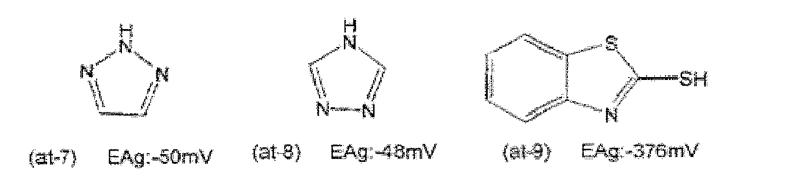


- Among them, the compounds indicated by at-20 and at-21 are particularly preferred since satisfactory effects can be obtained.
- The method for incorporating the heterocyclic ring compound into the flat metal particle-containing composition is preferably the following methods, but employable methods should not be construed as being limited thereto.
- A solution of the heterocyclic ring compound may be added to the flat metal particle-containing composition before coating of the flat metal particle-containing composition. The mixing period after addition of the heterocyclic ring compound solution is preferably 1 min to 60 min, more preferably 2 min to 30 min. The temperature of the mixture (dispersion liquid) during mixing is preferably 20°C to 80°C, more preferably 30°C to 60°C.
- The heterocyclic ring compound is dissolved in a solvent such as water or methanol. Then, coating of the resultant solution may be performed simultaneously with coating of the flat metal particle-containing composition. In this case, the flat metal particle-containing composition and the heterocyclic ring compound solution may be mixed together immediately before coating, or may be coated as separate layers. Alternatively, the heterocyclic ring compound solution may be coated after coating of the flat metal particle-containing composition.
- Also, a sample obtained through coating of the flat metal particle-containing composition may be immersed in the heterocyclic ring compound solution In this case, the immersion time is preferably 1 min to 60 min, further preferably 2 min to 30 min. The temperature of the solution during immersion is preferably 10°C to 60°C, further preferably 20°C to 50°C. The concentration of the heterocyclic ring compound solution is preferably 0.1% by mass to 10% by mass, more preferably 0.5% by mass to 5% by mass.
- The amount of the heterocyclic ring compound added is preferably 1 × 10⁻⁵ mol to 1 mol, further preferably 5 × 10⁻⁵ mol to 1 × 10⁻¹ mol, particularly preferably 1 × 10⁻⁴ to 5 × 10⁻² mol, per 1 mol of the metal contained in the flat metal particle-containing composition.
- The flat metal particle-containing composition of the present invention may appropriately contain various additives such as a surfactant, a polymerizable compound, an antioxidant, a sulfurization inhibitor, a corrosion inhibitor, a viscosity adjuster and an antiseptic agent.
- In the flat metal particle-containing composition of the present invention, the flat metal particles exist more stably and reduction of plasmon reflection due to light can be prevented. Thus, the flat metal particle-containing composition can be suitably used in, for example, a heat ray reflection film, an infrared ray reflection film, a visible light reflection film, a heat ray absorption film, an infrared ray absorption film and a selective reflection film. Furthermore, the flat metal particle-containing composition has high selectivity for reflection wavelength or region, has excellent transmittance with respect to visible light and radio wave and has excellent light resistance, and thus, can be suitably used as the below-described heat ray-shielding material.
- A heat ray-shielding material of the present invention contains the above-described flat metal particle-containing composition of the present invention; and, if necessary, may further contains other members.
- The heat ray-shielding material includes a substrate and a flat metal particle-containing layer formed of the flat metal particle-containing composition of the present invention; and, if necessary, further includes other members.
- The flat metal particle-containing layer is not particularly limited and may be appropriately selected depending on the intended purpose, so long as it is formed of the flat metal particle-containing composition of the present invention and is provided on the substrate.
- The flat metal particle-containing layer may be formed by coating the substrate with the flat metal particle-containing composition of the present invention. Examples of the coating method include spin coating, dip coating, extrusion coating, bar coating and die coating.
- The substrate is not particularly limited, so long as it is optically transparent, and may be appropriately selected depending on the intended purpose. For example, the substrate is a substrate having a visible light transmittance of 70% or higher, preferably 80% or higher, or a substrate having a high transmittance with respect to lights of the near-infrared region.
- The material for the substrate is not particularly limited and may be appropriately selected depending on the intended purpose. Examples thereof include glass materials (e.g., a white glass plate and a blue glass plate), polyethylene terephthalate (PET) and triacetylcellulose (TAC).
- The heat ray-shielding material of the present invention preferably contains a protective layer for improving the adhesion to the substrate and mechanically protecting the resultant product.
- The protective layer is not particularly limited and may be appropriately selected depending on the intended purpose. The protective layer contains, for example, a binder, a surfactant and a viscosity adjuster; and, if necessary, further includes other ingredients.
- The binder is not particularly limited and may be appropriately selected depending on the intended purpose. The binder preferably has higher transparency with respect to visible light and solar radiation. Examples thereof include acrylic resins, polyvinylbutyrals and polyvinylalcohols. Notably, when the binder absorbs heat rays, the reflection effects of the flat metal particles are disadvantageously weakened. Thus, when an intermediate layer is formed between the heat ray source and the flat metal particles, preferably, a material having no absorption of light having a wavelength of 780 nm to 1,500 nm is selected or the thickness of the protective layer is made small.
- In one embodiment of the heat ray-shielding material of the present invention, the flat metal particles are arranged so that their mane planes are plane-oriented at a predetermined angle with respect to a surface of the substrate.
- The manner in which the flat metal particles are arranged is not particularly limited and may be appropriately selected depending on the intended purpose. Preferably, the flat metal particles are arranged in substantially parallel with the substrate surface, from the viewpoint of increasing heat ray reflectivity.
- The manner in which the flat metal particles are plane-oriented is not particularly limited and may be appropriately selected depending on the intended purpose, so long as main planes of the flat metal particles are in substantially parallel with the substrate surface within a predetermined angle range. The angle formed between the substrate surface and the main planes of the flat metal particles is preferably 0° to ±30°, more preferably 0° to ±20°, further preferably 0° to ±5°. Here,
Figs. 2A to 2C are each a schematic cross-sectional view of the metal particle-containing layer containing the flat metal particles in a heat ray-shielding material of the present invention.Fig. 2A illustratesflat metal particles 3 existing in a metal particle-containinglayer 2 in an ideal state.Fig. 2B explains angles (±θ) formed between a surface of asubstrate 1 and planes offlat particles 3.Fig. 2C illustrates a region where flat metal particles exist in a depth direction of a metal particle-containinglayer 2 of the heat ray-shielding material. Notably, a vertical two-sided arrow inFig. 2C indicates a region f(λ) where the particles exist. - The above-described predetermined angle range of the plane orientation corresponds to angles (±θ) formed between the surface of the
substrate 1 and the main planes of theflat metal particles 3 or extended lines of the main planes, as shown inFig. 2B . That is, the term "plane orientation" refers to a state where the angles (±θ) shown inFig. 2B are small when the cross section of the heat ray-shielding material is observed. In particular,Fig. 2A illustrates a state where the surface of thesubstrate 1 is in contact with the main planes of theflat metal particles 3; i.e., the angles θ are 0°. When the main planes of theflat metal particles 3 are plane-oriented on the surface of thesubstrate 1 at angles exceeding ±30°; i.e., when the angles θ shown inFig. 2B exceed ±30°, the heat ray-shielding material has degraded reflectance to light of a predetermined wavelength (for examples, from a longer wavelength region of the visible light range to the near infrared region) and exhibits large haze, which is not preferred. - The method for evaluating whether the main planes of the flat metal particles are plane-oriented on the surface of the substrate is not particularly limited and may be appropriately selected depending on the intended purpose. Examples thereof include a method including preparing appropriate cross-sectional pieces and observing the substrate and the flat metal particles in the pieces. In one specific method, the heat ray-shielding material is cut with a microtome or a focused ion beam (FIB) to prepare cross-sectional samples or cross-sectional pieces of the heat ray-shielding material; the thus-prepared samples or pieces are observed with various microscopes (e.g., a field emission scanning electron microscope (FE-SEM)); and the obtained images are used for evaluation.
- When the binder covering the flat metal particles of the heat ray-shielding material is swelled with water, the cross-sectional samples or cross-sectional pieces may be prepared by freezing the heat ray-shielding material in liquid nitrogen and by cutting the resultant sample with a diamond cutter equipped with a microtome. In contrast, when the binder covering the flat metal particles of the heat ray-shielding material is not swelled with water, the cross-sectional samples or cross-sectional pieces may be prepared directly.
- The method for observing the above-prepared cross-sectional samples or cross-sectional pieces is not particularly limited and may be appropriately selected depending on the intended purpose, so long as the method can determine whether or not the main planes of the flat metal particles are plane-oriented on the surface of the substrate in the samples. The observation can be performed with, for example, a FE-SEM, a TEM and an optical microscope. The cross-sectional samples may be observed with a FE-SEM and the cross-sectional pieces may be observed with a TEM. When the FE-SEM is used for evaluation, the FE-SEM preferably has a spatial resolution with which the shapes of the flat metal particles and the angles (±θ shown in
Fig. 2B ) can be clearly observed. - In the heat ray-shielding material of the present invention, as shown in
Fig. 2C , the metal particle-containinglayer 2 preferably exists within a range of (λ/n)/4 in a depth direction from the horizontal surface of the heat ray-shielding material, where λ, denotes a plasmon resonance wavelength of the metal forming theflat metal particles 3 contained in the metal particle-containinglayer 2 and n denotes a refractive index of the medium of the metal particle-containinglayer 2. When the metal particle-containinglayer 2 exists in a broader range than this range, the effect of strengthening the phases becomes small at the interfaces between air and the front and rear surfaces of the heat ray-shielding material, potentially leading to a decrease in visible light transmittance and the maximum reflectance to heat rays. - The plasmon resonance wavelength λ of the metal forming the flat metal particles contained in the metal particle-containing layer is not particularly limited and may be appropriately selected depending on the intended purpose. The plasmon resonance wavelength λ is preferably 400 nm to 2,500 nm from the viewpoint of exhibiting heat ray reflectivity. More preferably, the plasmon resonance wavelength λ is 700 nm to 2,500 nm from the viewpoint of reducing haze (scattering) of visible light.
- The medium of the metal particle-containing layer is not particularly limited and may be appropriately selected depending on the intended purpose. Examples thereof include polyvinylacetal resins, polyvinylalcohol resins, polyvinylbutyral resins, polyacrylate resins, polymethyl methacrylate resins, polycarbonate resins, polyvinyl chloride resins, saturated polyester resins, polyurethane resins, polymers such as naturally occurring polymers (e.g., gelatin and cellulose) and inorganic compounds (e.g. silicon dioxide and aluminum oxide).
- The refractive index n of the medium is preferably 1.4 to 1.7.
- When A and B denote respectively a projected area of the substrate and the total value of projected areas of the flat metal particles when the heat ray-shielding material is viewed from a perpendicular direction, the area ratio of (B/A) × 100 is preferably 15% or higher, more preferably 20% or higher. When the area ratio is lower than 15%, the maximum reflectivity to heat rays is decreased, resulting in that satisfactory heat-shielding effects cannot be obtained in some cases.
- The area ratio can be measured, for example, as follows. Specifically, the heat ray-shielding material is observed under a SEM or an AFM (atomic force microscope) and the resultant image is subjected to image processing.
- In the metal particle-containing layer, the average interparticle distance between the flat metal particles neighboring in a horizontal direction is preferably equal to or larger than 1/10 the average particle diameter of the flat metal particles from the viewpoint of obtaining desired visible light transmittance and the maximum reflectance to heat rays.
- When the average interparticle distance of the flat metal particles in a horizontal direction is lower than 1/10 the average particle diameter of the flat metal particles, the maximum reflectance to heat rays is disadvantageously decreased. Also, the average interparticle distance in a horizontal direction is preferably ununiform (random) from the viewpoint of obtaining visible light transmittance. When the average interparticle distance is not random; i.e., uniform, the metal particle-containing layer absorbs visible light, resulting in that its transmittance may be decreased.
- Here, the average interparticle distance of the flat metal particles in a horizontal direction refers to an average value of interparticle distances between two neighboring particles. Also, the description "the average interparticle distance is random" means that there is no significant local maximum point except for the origin in a two-dimensional autocorrelation of brightness values when binarizing a SEM image containing 100 or more of flat metal particles.
- In the heat ray-shielding material of the present invention, the flat metal particles are arranged in the form of the metal particle-containing layer containing the flat metal particles, as shown in
Figs. 2A to 2C . - The metal particle-containing layer may be a single layer as shown in
Figs. 2A to 2C . Alternatively, two or more of the metal particle-containing layer may be provided. Provision of two or more of the metal particle-containing layer attains desired shielding of light of a desired wavelength region. - The production method for the heat ray-shielding material of the present invention is not particularly limited and may be appropriately selected depending on the intended purpose. In one employable method, a substrate is coated with a dispersion liquid containing the flat metal particles using, for example, a dip coater, a die coater, a slit coater, a bar coater or a gravure coater. In another employable method, the flat metal particles are plane-oriented by, for example, an LB film method, a self-organizing method and a spray method.
- Also, a method utilizing electrostatic interactions may be applied to plane orientation in order to increase adsorbability or plane orientability of the flat metal particles on the substrate surface. Specifically, when the surfaces of the flat metal particles are negatively charged (for example, when the flat metal particles are dispersed in a negatively chargeable medium such as citric acid), the substrate surface is positively charged (for example, the substrate surface is modified with an amino group, etc.) to electrostatically enhance plane orientability. Also, when the surfaces of the flat metal particles are hydrophilic, the substrate surface may be provided with a sea-island structure having hydrophilic and hydrophobic regions using, for example, a block copolymer or a micro contact stamp, to thereby control the plane orientability and the interparticle distance of the flat metal particles utilizing hydrophilic-hydrophobic interactions.
- Notably, the coated flat metal particles are allowed to pass through pressure rollers (e.g., calender rollers or rami rollers) to promote their plane orientation.
- The solar reflectance of the heat ray-shielding material of the present invention is preferably maximal in the range of 600 nm to 2,000 nm (preferably 700 nm to 1,600 nm) from the viewpoint of increasing efficiency of heat ray reflection.
- The heat ray-shielding material of the present invention preferably has a visible light transmittance of 60% or higher. When the visible light transmittance thereof is lower than 60%, one may difficult to see through automotive glass or building glass using the heat ray-shielding material.
- The heat ray-shielding material of the present invention preferably has a haze of 20% or lower. When the haze thereof exceeds 20%, one may difficult to see through automotive glass or building glass using the heat ray-shielding material, which is not preferred in terms of safety.
- The usage form of the heat ray-shielding material of the present invention is not particularly limited and may be appropriately selected depending on the intended purpose. Examples thereof include vehicles' glass or films, building glass or films and agricultural films. Among them, the heat ray-shielding material is preferably used as vehicles' glass or films and building glass or films in terms of energy saving.
- Notably, in the present invention, heat rays (near infrared rays) refer to near infrared rays (780 nm to 2,500 nm) accounting for about 50% of sunlight.
- The production method for the glass is not particularly limited and may be appropriately selected depending on the intended purpose. In one employable method, the heat ray-shielding material produced in the above-described manner is provided with an adhesive layer, and the resultant laminate is attached onto vehicle's glass (e.g., automotive glass) or building glass or is inserted together with a PVB or EVA intermediate film used in laminated glass. Alternatively, only particle/binder layer may be transferred onto a PVB or EVA intermediate film; i.e., the substrate may be peeled off in use.
- The present invention will next be described by way of Examples, which should not be construed as limiting the present invention thereto.
- The silver interaction potential EAg of the heterocyclic ring compounds used in Examples and Comparative Examples was measured as follows.
- The silver interaction potential EAg can be measured by the following silver interaction potential method.
- First, there is prepared a solution (50 mL) containing a heterocyclic ring compound at a concentration of 0.00100 M, potassium bicarbonate at a concentration of 0.0200 M and potassium carbonate at a concentration of 0.0267 M. The pH of the prepared solution is adjusted to 10.0 with 1 M nitric acid or sodium hydroxide. Then, 1 mL of 0.00500 M silver nitrate was added to the resultant solution at 20°C to 25°C with magnetic stirring. The potential of the solution 15 min after the addition of the silver nitrate was measured by an electrochemical method using a calomel electrode. The potential (mV) thusly measured is a silver interaction potential.
- A 0.5 g/L aqueous polystyrenesulfonic acid solution (2.5 mL) was added to a 2.5 mM aqueous sodium citrate solution (50 mL), followed by heating to 35°C. Then, a 10 mM sodium borohydride solution (3 mL) was added to the resultant solution. Next, a 0.5 mM aqueous silver nitrate solution (50 mL) was added thereto at 20 mL/min under stirring. This solution was stirred for 30 min to prepare a seed particle solution (the synthesis step of flat nuclear particles).
- Next, ion-exchanged water (87.1 mL) was added to a 2.5 mM aqueous sodium citrate solution (132.7 mL), followed by heating to 35°C. Subsequently, a 10 mM aqueous ascorbic acid solution (2 mL) was added to the resultant solution and then 42.4 mL of the above-prepared seed particle solution was added thereto. Further, a 0.5 mM aqueous silver nitrate solution (79.6 mL) was added thereto at 10 mL/min under stirring (the first growth step of flat particles).
- Next, the above-obtained solution was stirred for 30 min, and then a 0.35 M aqueous potassium hydroquinonesulfonate solution (71.1 mL) was added thereto. Further, 200 g of a 7% by mass aqueous gelatin solution was added thereto. Separately, 0.25 M aqueous sodium sulfite solution (107 mL) and a 0.47 M aqueous silver nitrate solution (107 mL) were mixed together to prepare a mixture containing white precipitates. The thus-prepared mixture was added to the solution to which the aqueous gelatin solution had been added. Immediately after the addition of the mixture containing white precipitates, a 0.17 M aqueous NaOH solution (72 mL) was added to the resultant mixture. Here, the aqueous NaOH solution was added thereto at an addition rate adjusted so that the pH of the mixture did not exceed 10. The thus-obtained mixture was stirred for 300 min to prepare a dispersion liquid of flat silver particles (the second growth step of flat particles).
- The obtained flat silver particle dispersion liquid was found to contain hexagonal flat silver particles. Also, the obtained flat silver particles were measured for various properties as follows. The results are shown in Table 1.
- Referring to "ACSNANO Vol. 3., No. 1., pp. 21-26," silver nanorods were produced. The produced silver nanorods were found to have a major axis of 250 nm, a minor axis of 42 nm and an aspect ratio (major axis/minor axis) of 6.
- The average particle diameter of the flat silver particles was obtained as follows. Specifically, 200 particles were randomly selected from the SEM image observed. Then, image processing was performed on their shapes, with A and B corresponding respectively to substantially hexagonal or disc-like particles and amorphous particles (e.g., drop-like particles). Subsequently, particles corresponding to A were measured for equivalent circle diameter with a digital caliper. The average value of the equivalent circle diameters was defined as an average particle diameter. Moreover, the standard deviation of the equivalent circle diameters was divided by the average particle diameter to obtain variation coefficient (%).
- The dispersion liquid containing flat silver particles was dropped on a glass substrate, followed by drying. Then, the thickness of each flat silver particle was measured with an atomic force microscope (AFM) (Nanocute II, product of Seiko Instruments Inc.). Notably, the measurement conditions of AFM were as follows: self-detection sensor, DFM mode, measurement range: 5 µm, scanning speed: 180 sec/frame and the number of data: 256 × 256.
- The average particle diameter was divided by the average particle thickness to obtain an aspect ratio of the obtained flat silver particles (average particle diameter/average particle thickness).
Table 1 Shape Ratio of flat metal particles
(or rods)
(% by number)Average particle diameter
(nm)Average particle thickness
(nm)Aspect ratio Variation coefficient of particle size distribution
(%)Production Example 1 Substantially hexagonal 84 230 16 14.3 28 Production Example 2 Rod 93 (250) (42) (6) 17 *In the rods in Table 1, the average particle diameter is the major axis thereof, the average particle thickness is the minor axis thereof, and the aspect ratio is a value obtained by dividing the average particle diameter with the average particle thickness - First, 1 N NaOH (0.75 mL) was added to the flat silver particle dispersion liquid (16 mL) of Production Example 1. Then, ion-exchanged water (24 mL) was added to the resultant mixture, followed by centrifugating with a centrifuge (product of KOKUSAN Co., Ltd., H-200N, Angle Rotor BN) at 5,000 rpm for 5 min, to thereby precipitate hexagonal flat silver particles. The supernatant after the centrifugation was removed and then water (5 mL) was added thereto to re-disperse the precipitated hexagonal flat silver particles. Thereafter, 1.6 mL of a 2% by mass solution of compound W-1 having the following structural formula in water and methanol was added to the resultant dispersion liquid for preparing a coating liquid. The thus-prepared coating liquid was applied onto a polyethylene terephthalate (PET) film with a wire coating bar No. 14, followed by drying, to thereby obtain a film on which hexagonal flat silver particles were fixed.
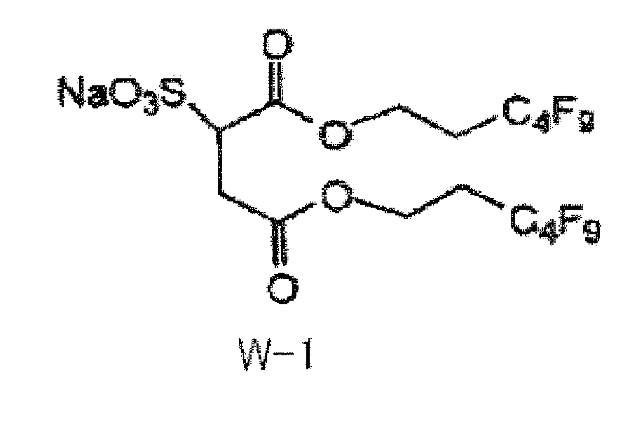
- The hexagonal flat silver particles were fixed on the PET film without aggregation. Through the above procedure, a heat ray-shielding material of sample No. 104 was produced.
- The procedure of sample No. 104 was repeated, except that the flat silver particle dispersion liquid of Production Example 1 was changed to the silver nanorod dispersion of Production Example 2, to thereby produce a heat ray-shielding material of sample No. 101.
- The procedure of sample No. 101 was repeated, except that Comparative Compound A having the following structural formula was added in an amount of 3.0 × 10⁻³ mole relative to 1 mole of silver contained in the silver nanorod dispersion of Production Example 2, to thereby produce a heat ray-shielding material of sample No. 102.

- The procedure of sample No. 101 was repeated, except that Compound at-12 having the following structural formula was added in an amount of 3.0 × 10⁻³ mole relative to 1 mole of silver contained in the silver nanorod dispersion of Production Example 2, to thereby produce a heat ray-shielding material of sample No. 103.

- The procedure of sample No. 104 was repeated, except that Comparative Compound A having the above structural formula was added in an amount of 3.0 × 10⁻³ mole relative to 1 mole of silver contained in the flat silver particle dispersion of Production Example 1, to thereby produce a heat ray-shielding material of sample No. 105.
- The procedure of sample No. 104 was repeated, except that Comparative Compound B having the following structural formula was added in an amount of 3.0 × 10⁻³ mole relative to 1 mole of silver contained in the flat silver particle dispersion of Production Example 1, to thereby produce a heat ray-shielding material of sample No. 106.

- The procedure of sample No. 104 was repeated, except that Compound at-12 having the above structural formula was added in an amount of 3.0 × 10⁻³ mole relative to 1 mole of silver contained in the flat silver particle dispersion of Production Example 1, to thereby produce a heat ray-shielding material of sample No. 107.
- The procedure of sample No. 104 was repeated, except that Compound at-20 having the following structural formula was added in an amount of 3.0 × 10⁻³ mole relative to 1 mole of silver contained in the flat silver particle dispersion of Production Example 1, to thereby produce a heat ray-shielding material of sample No. 108.

- The procedure of sample No. 104 was repeated, except that Compound at-21 having the following structural formula was added in an amount of 3.0 × 10⁻³ mole relative to 1 mole of silver contained in the flat silver particle dispersion of Production Example 1, to thereby produce a heat ray-shielding material of sample No. 109.

- The procedure of sample No. 104 was repeated, except that Compound at-11 having the following structural formula was added in an amount of 3.0 × 10⁻³ mole relative to 1 mole of silver contained in the flat silver particle dispersion of Production Example 1, to thereby produce a heat ray-shielding material of sample No. 110.

- The procedure of sample No. 104 was repeated, except that Compound at-19 having the following structural formula was added in an amount of 3.0 × 10⁻³ mole relative to 1 mole of silver contained in the flat silver particle dispersion of Production Example 1, to thereby produce a heat ray-shielding material of sample No. 111.

- Next, each of the thus-produced heat ray-shielding materials was evaluated for various properties. The results are shown in Table 1.
- Each of the produced heat ray-shielding materials was measured for transmission spectrum and reflection spectrum according to the JIS evaluation standard for automotive glass.
- The transmission and reflection spectra were evaluated with a UV-Vis near infrared spectrophotometer (product of JASCO Corporation, V-670). The evaluation was performed using an absolute reflectance measurement unit (ARV-474, product of JASCO Corporation). Here, incident light was caused to pass through a 45° polarization plate so as to become substantially non-polarized light.
- The heat ray maximum reflectance was measured according to the method of JIS-R3106: 1998 "Testing method on transmittance, reflectance and emittance of flat glasses and evaluation of solar heat gain coefficient." After initial measurement ranging from 300 nm to 2,100 nm, the maximum reflectance was defined as the infrared ray maximum reflectance. Specifically, using SUPER XENON WEATHER METER SX-75 (product of Suga Test Instruments Co., Ltd.), each heat ray-shielding material was irradiated with xenon light for 4 weeks under the conditions: 180 W/m2, black panel temperature: 63°C and humidity: 25%RH, and then the maximum reflectance of the material was defined as the infrared ray maximum reflectance.
- Meanwhile, the visible light transmittance was measured as follows. Each heat ray-shielding material was measured for transmittance with respect to each wavelength ranging from 380 nm to 780 nm, and the thus-measured transmittances were corrected with the luminosity factor of each wavelength.
- Each of the obtained heat ray-shielding materials was observed under a scanning electron microscope (SEM). The obtained SEM image was binarized to determine an area ratio of (B/A) × 100, where A and B denote respectively a projected area of the substrate and the total value of projected areas of the flat metal particles when the heat ray-shielding material is viewed from a perpendicular direction.
- Each of the obtained heat ray-shielding materials was embedded in an epoxy resin, followed by freezing in liquid nitrogen. In this state, the freezed product was cut with a razor to prepare a vertically cross-sectional sample of the heat ray-shielding material. The thus-prepared vertically cross-sectional sample was observed under a scanning electron microscope (SEM). Then, 100 flat metal particles were examined for tilt angle with respect to the horizontal surface of the substrate, to calculate the average tilt angle of the flat metal particles.
- Using a haze meter (NDH-5000, NIPPON DENSHOKU INDUSTRIES CO., LTD.), each heat ray-shielding material was measured for haze value (%).
Table 2-1 Sample No. Particle Heterocyclic ring compound Visible light
(550nm)Initial After Xe irradiation Infrared light
(800mn to 2000nm)Infrared light
(800nm to 2000nm)Compd. EAg
(mV)Amount
(mol)Transmittance
(%)Max. reflectance
(%)Max. absorbance
(%)Max. reflectance
(%)Max. absorbance
(%)101 Rod - - - 85 7 43 7 42 Comp. Ex. 102 Rod Comp. Compd. A -1 3×10⁻³ 85 8 43 8 42 Comp. Ex. 103 Rod at-12 -152 3×10⁻³ 85 8 42 8 41 Comp. Ex. 104 Flat - - - 80 58 8 40 15 Comp. Ex. 105 Flat Comp. Compd. A -1 3×10⁻³ 78 56 9 42 13 Comp. Ex. 106 Flat Comp. Compd. B 57 3×10⁻³ 76 57 7 40 16 Comp. Ex. 107 Flat at-12 -152 3×10⁻³ 79 55 8 50 10 Present Invention 108 Flat at-20 -230 3×10⁻³ 78 57 8 55 9 Present Invention 109 Flat at-21 -240 3×10⁻³ 79 54 9 54 9 Present Invention 110 Flat at-11 -96 3×10⁻³ 78 58 8 57 9 Present Invention 111 Flat at-19 -520 3×10⁻³ 77 57 4 51 9 Present Invention Table 2-2 Sample No. Tilt angle of flat metal particles Area ratio (%) Haze value (%) 101 - - 0.9 Comp. Ex. 102 - - 0.8 Comp. Ex. 103 - - 0.8 Comp. Ex. 104 5° 45 1.2 Comp. Ex. 105 5° 45 1.2 Comp. Ex. 106 5° 45 1.2 Comp. Ex. 107 5° 45 1.2 Present Invention 108 5° 45 1.2 Present Invention 109 5° 45 1.3 Present Invention 110 5° 45 1.1 Present Invention 111 5° 45 1.2 Present Invention - As is clear from Table 2-1, the heat ray-shielding materials of the present invention were found to exhibit a higher infrared reflectance than those of the heat ray-shielding materials of Comparative Examples. In addition, the heat ray-shielding materials of the present invention did not decrease in infrared reflectance after irradiation of Xe light than did the heat ray-shielding materials of Comparative Examples.
- In the flat metal particle-containing composition of the present invention, the flat metal particles exist more stably and reduction of plasmon reflection due to light can be prevented. Thus, the flat metal particle-containing composition can be suitably used in, for example, a heat ray reflection film, an infrared ray reflection film, a visible light reflection film, a heat ray absorption film, an infrared ray absorption film and a selective reflection film.
- Furthermore, the heat ray-shielding material of the present invention has high selectivity for reflection wavelength or region, has excellent transmittance with respect to visible light and radio wave and has excellent light resistance, and thus, can be suitably used as various members required for shielding heat rays, such as glass of vehicles (e.g., automobiles and buses), building glass and agricultural films.
Claims (8)
- A flat metal particle-containing composition comprising:flat metal particles, anda heterocyclic ring compound,wherein the heterocyclic ring compound has a silver interaction potential EAg which is lower than -1 mV.
- The flat metal particle-containing composition according to claim 1, wherein the silver interaction potential EAg of the heterocyclic ring compound is -300 mV or higher but lower than -1 mV.
- The flat metal particle-containing composition according to claim 1 or 2, wherein the flat metal particles contain silver, gold, copper or an alloy thereof.
- The flat metal particle-containing composition according to any one of claims 1 to 3, wherein the flat metal particles contain silver.
- The flat metal particle-containing composition according to any one of claims 1 to 4, wherein the flat metal particle-containing composition is used for a heat ray reflection film, an infrared ray reflection film, a heat ray absorption film, an infrared ray absorption film or a selective reflection film.
- A heat ray-shielding material comprising:the flat metal particle-containing composition according to any one of claims 1 to 4.
- The heat ray-shielding material according to claim 6, further comprising a substrate and a flat metal particle-containing layer on the substrate, wherein the flat metal particle-containing layer is formed of the flat metal particle-containing composition, and main planes of the flat metal particles are plane-oriented at 0° to ±30° with respect to a surface of the substrate.
- The heat ray-shielding material according to claim 7, wherein the heat ray-shielding material has an area ratio of 15% or higher, the area ratio being calculated by B/A × 100, where A and B denote a projected area of the substrate and a total value of projected areas of the flat metal particles, respectively, when the heat ray-shielding material is viewed from a perpendicular direction.
Applications Claiming Priority (1)
| Application Number | Priority Date | Filing Date | Title |
|---|---|---|---|
| JP2010088187A JP5570279B2 (en) | 2010-04-06 | 2010-04-06 | Heat ray shielding material |
Publications (3)
| Publication Number | Publication Date |
|---|---|
| EP2383057A2 true EP2383057A2 (en) | 2011-11-02 |
| EP2383057A3 EP2383057A3 (en) | 2012-05-30 |
| EP2383057B1 EP2383057B1 (en) | 2014-10-01 |
Family
ID=44170154
Family Applications (1)
| Application Number | Title | Priority Date | Filing Date |
|---|---|---|---|
| EP11161114.1A Not-in-force EP2383057B1 (en) | 2010-04-06 | 2011-04-05 | Flat metal particle-containing composition and heat ray-shielding material |
Country Status (4)
| Country | Link |
|---|---|
| US (1) | US20110240905A1 (en) |
| EP (1) | EP2383057B1 (en) |
| JP (1) | JP5570279B2 (en) |
| CN (1) | CN102249548B (en) |
Cited By (1)
| Publication number | Priority date | Publication date | Assignee | Title |
|---|---|---|---|---|
| CN110476091A (en) * | 2017-03-28 | 2019-11-19 | 富士胶片株式会社 | High refractive index film and optical interference film |
Families Citing this family (14)
| Publication number | Priority date | Publication date | Assignee | Title |
|---|---|---|---|---|
| JP5518580B2 (en) * | 2010-06-03 | 2014-06-11 | 富士フイルム株式会社 | Heat ray shielding material |
| JP5825797B2 (en) * | 2011-02-08 | 2015-12-02 | 株式会社ブリヂストン | Evaluation method for polymer materials |
| JP5828824B2 (en) * | 2012-09-28 | 2015-12-09 | 富士フイルム株式会社 | Metal tabular grain dispersion, method for producing metal tabular grain dispersion, and heat ray shielding material |
| JP6110105B2 (en) * | 2012-11-05 | 2017-04-05 | ユニチカ株式会社 | Method for producing silver fine particles |
| JP6284762B2 (en) * | 2013-12-18 | 2018-02-28 | 富士フイルム株式会社 | Heat shield and window glass |
| EP3037161B1 (en) * | 2014-12-22 | 2021-05-26 | Agfa-Gevaert Nv | A metallic nanoparticle dispersion |
| JP2016173499A (en) * | 2015-03-17 | 2016-09-29 | 富士フイルム株式会社 | Heat insulation film, heat insulation glass and window |
| JP6580248B2 (en) * | 2016-02-29 | 2019-09-25 | 富士フイルム株式会社 | Ink composition and image forming method |
| EP3469030B1 (en) * | 2016-06-08 | 2021-08-11 | Agfa-Gevaert Nv | An inkjet ink set for preparing conductive layers or patterns |
| JP6663079B2 (en) | 2017-03-31 | 2020-03-11 | 富士フイルム株式会社 | Gold-coated silver tabular particles, gold-coated silver tabular particle dispersion, method for producing the same, coating film, and antireflection optical member |
| WO2018221093A1 (en) * | 2017-05-30 | 2018-12-06 | 富士フイルム株式会社 | Heat ray shielding material, heat shielding glass, and laminated glass |
| US10851257B2 (en) * | 2017-11-08 | 2020-12-01 | Eastman Kodak Company | Silver and copper nanoparticle composites |
| JP6752392B2 (en) | 2018-03-29 | 2020-09-09 | 富士フイルム株式会社 | Wavelength selective absorption material, infrared sensor, wavelength selective light source and radiative cooling system |
| CN116031326B (en) * | 2022-10-25 | 2025-05-13 | 中国科学院合肥物质科学研究院 | A non-close-packed noble metal nanoparticle ordered lattice and preparation method thereof |
Citations (3)
| Publication number | Priority date | Publication date | Assignee | Title |
|---|---|---|---|---|
| JP3594803B2 (en) | 1997-07-17 | 2004-12-02 | 日本ペイント株式会社 | Noble metal or copper colloid solution, method for producing the same, coating composition and resin molded product |
| US20070074316A1 (en) | 2005-08-12 | 2007-03-29 | Cambrios Technologies Corporation | Nanowires-based transparent conductors |
| JP2009146678A (en) | 2007-12-13 | 2009-07-02 | Konica Minolta Holdings Inc | Transparent conductive film and its manufacturing method |
Family Cites Families (5)
| Publication number | Priority date | Publication date | Assignee | Title |
|---|---|---|---|---|
| JP4540945B2 (en) * | 2003-06-26 | 2010-09-08 | 住友大阪セメント株式会社 | Coating for forming metal thin film, metal thin film and method for producing the same |
| DE102005061684A1 (en) * | 2005-12-21 | 2007-06-28 | Eckart Gmbh & Co. Kg | Infrared radiation reflecting pigment, useful e.g. in color, lacquers and printing ink, comprises an infrared reflecting core with permeable or encasing coating for infrared-radiation |
| JP2008001844A (en) * | 2006-06-23 | 2008-01-10 | Fujifilm Corp | Metal fine particle-containing composition, ink for forming colored film for display, photosensitive material, photosensitive transfer material, substrate with shading image, color filter, liquid crystal display element and liquid crystal display |
| US20100001237A1 (en) * | 2007-03-26 | 2010-01-07 | Fornes Timothy D | Method for producing heterogeneous composites |
| WO2009122467A1 (en) * | 2008-04-04 | 2009-10-08 | ニホンハンダ株式会社 | Method for joining metallic members, metallic member joined product, and method for manufacturing bump for electric circuit connection |
-
2010
- 2010-04-06 JP JP2010088187A patent/JP5570279B2/en active Active
-
2011
- 2011-04-01 US US13/078,539 patent/US20110240905A1/en not_active Abandoned
- 2011-04-05 EP EP11161114.1A patent/EP2383057B1/en not_active Not-in-force
- 2011-04-06 CN CN201110087586.6A patent/CN102249548B/en active Active
Patent Citations (3)
| Publication number | Priority date | Publication date | Assignee | Title |
|---|---|---|---|---|
| JP3594803B2 (en) | 1997-07-17 | 2004-12-02 | 日本ペイント株式会社 | Noble metal or copper colloid solution, method for producing the same, coating composition and resin molded product |
| US20070074316A1 (en) | 2005-08-12 | 2007-03-29 | Cambrios Technologies Corporation | Nanowires-based transparent conductors |
| JP2009146678A (en) | 2007-12-13 | 2009-07-02 | Konica Minolta Holdings Inc | Transparent conductive film and its manufacturing method |
Non-Patent Citations (2)
| Title |
|---|
| ACSNANO, vol. 3, no. 1, pages 21 - 26 |
| LANGMUIR, vol. 16, 2000, pages 2731 - 2735 |
Cited By (1)
| Publication number | Priority date | Publication date | Assignee | Title |
|---|---|---|---|---|
| CN110476091A (en) * | 2017-03-28 | 2019-11-19 | 富士胶片株式会社 | High refractive index film and optical interference film |
Also Published As
| Publication number | Publication date |
|---|---|
| CN102249548B (en) | 2016-08-10 |
| US20110240905A1 (en) | 2011-10-06 |
| JP5570279B2 (en) | 2014-08-13 |
| EP2383057A3 (en) | 2012-05-30 |
| JP2011221149A (en) | 2011-11-04 |
| CN102249548A (en) | 2011-11-23 |
| EP2383057B1 (en) | 2014-10-01 |
Similar Documents
| Publication | Publication Date | Title |
|---|---|---|
| EP2383057B1 (en) | Flat metal particle-containing composition and heat ray-shielding material | |
| EP2374559B1 (en) | Flat metal particle-containing composition, use thereof and heat ray-shielding material | |
| Sugimoto et al. | Magnetic Purcell enhancement by magnetic quadrupole resonance of dielectric nanosphere antenna | |
| US8883045B2 (en) | Metal nanowire-containing composition, and transparent conductor | |
| Shi et al. | Gold nanoshells on polystyrene cores for control of surface plasmon resonance | |
| Wang et al. | Size control of semimetal bismuth nanoparticles and the UV− visible and IR absorption spectra | |
| Chang et al. | Hydrothermal synthesis of monodispersed octahedral gold nanocrystals with five different size ranges and their self-assembled structures | |
| CN110366461B (en) | Gold-coated silver flat particles, gold-coated silver flat particle dispersion, method for producing same, coating film, and antireflection optical member | |
| JP5457944B2 (en) | Silver tabular grain and method for producing the same, silver tabular grain-containing composition containing silver tabular grain, and film made of silver tabular grain-containing composition | |
| Nguyen et al. | New experimental evidences of Pt–Pd bimetallic nanoparticles with core–shell configuration and highly fine-ordered nanostructures by high-resolution electron transmission microscopy | |
| EP3191876B1 (en) | Solution-processable hri optical films comprising titanate nanoparticles | |
| Gunawidjaja et al. | Bimetallic nanostructures as active Raman markers: gold‐nanoparticle assembly on 1D and 2D silver nanostructure surfaces | |
| Bi et al. | Asymmetric structural colors based on monodisperse single-crystal Cu 2 O spheres | |
| Wang et al. | Effect of mirror quality on optical response of nanoparticle‐on‐mirror plasmonic nanocavities | |
| Long et al. | Novel issues of morphology, size, and structure of Pt nanoparticles in chemical engineering: surface attachment, aggregation or agglomeration, assembly, and structural changes | |
| Zeng et al. | Preparation and SERS study of triangular silver nanoparticle self‐assembled films | |
| Kulkarni et al. | Phase transfer of large anisotropic plasmon resonant silver nanoparticles from aqueous to organic solution | |
| Theobald et al. | Design of selective reflectors utilizing multiple scattering by core–shell nanoparticles for color conversion films | |
| Hassan et al. | Near-band-edge emission enhancement and suppression of the deep levels in Ga-doped ZnO via surface plasmon-exciton coupling without a dielectric spacer | |
| Li et al. | Hyperbolic metamaterials fabricated using 3D assembled nanorod arrays and enhanced photocatalytic performance | |
| Zhang et al. | Hexagonal core-shell and alloy Au/Ag nanodisks on ZnO nanorods and their optical enhancement effect | |
| JP5828824B2 (en) | Metal tabular grain dispersion, method for producing metal tabular grain dispersion, and heat ray shielding material | |
| Simonenko et al. | Microstructural evolution of silver nanowires when forming by the polyol method | |
| Noguchi et al. | Structural Color Materials with Color Mixing Effect Using Noble Metal‐Free Plasmonic Particles in SiO2–ZrN System | |
| Kumar et al. | Synthesis and characterization of PVA embedded with peanut-shaped AgcAus nanoparticles: optical and electrical properties |
Legal Events
| Date | Code | Title | Description |
|---|---|---|---|
| AK | Designated contracting states |
Kind code of ref document: A2 Designated state(s): AL AT BE BG CH CY CZ DE DK EE ES FI FR GB GR HR HU IE IS IT LI LT LU LV MC MK MT NL NO PL PT RO RS SE SI SK SM TR |
|
| AX | Request for extension of the european patent |
Extension state: BA ME |
|
| PUAI | Public reference made under article 153(3) epc to a published international application that has entered the european phase |
Free format text: ORIGINAL CODE: 0009012 |
|
| PUAL | Search report despatched |
Free format text: ORIGINAL CODE: 0009013 |
|
| AK | Designated contracting states |
Kind code of ref document: A3 Designated state(s): AL AT BE BG CH CY CZ DE DK EE ES FI FR GB GR HR HU IE IS IT LI LT LU LV MC MK MT NL NO PL PT RO RS SE SI SK SM TR |
|
| AX | Request for extension of the european patent |
Extension state: BA ME |
|
| RIC1 | Information provided on ipc code assigned before grant |
Ipc: B41M 5/42 20060101ALI20120423BHEP Ipc: B22F 1/00 20060101AFI20120423BHEP Ipc: A61Q 17/04 20060101ALI20120423BHEP |
|
| 17P | Request for examination filed |
Effective date: 20121120 |
|
| 17Q | First examination report despatched |
Effective date: 20130703 |
|
| GRAP | Despatch of communication of intention to grant a patent |
Free format text: ORIGINAL CODE: EPIDOSNIGR1 |
|
| INTG | Intention to grant announced |
Effective date: 20140514 |
|
| GRAS | Grant fee paid |
Free format text: ORIGINAL CODE: EPIDOSNIGR3 |
|
| GRAA | (expected) grant |
Free format text: ORIGINAL CODE: 0009210 |
|
| AK | Designated contracting states |
Kind code of ref document: B1 Designated state(s): AL AT BE BG CH CY CZ DE DK EE ES FI FR GB GR HR HU IE IS IT LI LT LU LV MC MK MT NL NO PL PT RO RS SE SI SK SM TR |
|
| RAP1 | Party data changed (applicant data changed or rights of an application transferred) |
Owner name: FUJIFILM CORPORATION |
|
| REG | Reference to a national code |
Ref country code: GB Ref legal event code: FG4D |
|
| REG | Reference to a national code |
Ref country code: AT Ref legal event code: REF Ref document number: 689255 Country of ref document: AT Kind code of ref document: T Effective date: 20141015 Ref country code: CH Ref legal event code: EP |
|
| REG | Reference to a national code |
Ref country code: IE Ref legal event code: FG4D |
|
| REG | Reference to a national code |
Ref country code: DE Ref legal event code: R096 Ref document number: 602011010206 Country of ref document: DE Effective date: 20141113 |
|
| REG | Reference to a national code |
Ref country code: NL Ref legal event code: VDEP Effective date: 20141001 |
|
| REG | Reference to a national code |
Ref country code: AT Ref legal event code: MK05 Ref document number: 689255 Country of ref document: AT Kind code of ref document: T Effective date: 20141001 |
|
| REG | Reference to a national code |
Ref country code: LT Ref legal event code: MG4D |
|
| PG25 | Lapsed in a contracting state [announced via postgrant information from national office to epo] |
Ref country code: NL Free format text: LAPSE BECAUSE OF FAILURE TO SUBMIT A TRANSLATION OF THE DESCRIPTION OR TO PAY THE FEE WITHIN THE PRESCRIBED TIME-LIMIT Effective date: 20141001 |
|
| PG25 | Lapsed in a contracting state [announced via postgrant information from national office to epo] |
Ref country code: IS Free format text: LAPSE BECAUSE OF FAILURE TO SUBMIT A TRANSLATION OF THE DESCRIPTION OR TO PAY THE FEE WITHIN THE PRESCRIBED TIME-LIMIT Effective date: 20150201 Ref country code: CZ Free format text: LAPSE BECAUSE OF FAILURE TO SUBMIT A TRANSLATION OF THE DESCRIPTION OR TO PAY THE FEE WITHIN THE PRESCRIBED TIME-LIMIT Effective date: 20141001 Ref country code: ES Free format text: LAPSE BECAUSE OF FAILURE TO SUBMIT A TRANSLATION OF THE DESCRIPTION OR TO PAY THE FEE WITHIN THE PRESCRIBED TIME-LIMIT Effective date: 20141001 Ref country code: FI Free format text: LAPSE BECAUSE OF FAILURE TO SUBMIT A TRANSLATION OF THE DESCRIPTION OR TO PAY THE FEE WITHIN THE PRESCRIBED TIME-LIMIT Effective date: 20141001 Ref country code: NO Free format text: LAPSE BECAUSE OF FAILURE TO SUBMIT A TRANSLATION OF THE DESCRIPTION OR TO PAY THE FEE WITHIN THE PRESCRIBED TIME-LIMIT Effective date: 20150101 Ref country code: LT Free format text: LAPSE BECAUSE OF FAILURE TO SUBMIT A TRANSLATION OF THE DESCRIPTION OR TO PAY THE FEE WITHIN THE PRESCRIBED TIME-LIMIT Effective date: 20141001 Ref country code: PT Free format text: LAPSE BECAUSE OF FAILURE TO SUBMIT A TRANSLATION OF THE DESCRIPTION OR TO PAY THE FEE WITHIN THE PRESCRIBED TIME-LIMIT Effective date: 20150202 |
|
| PG25 | Lapsed in a contracting state [announced via postgrant information from national office to epo] |
Ref country code: HR Free format text: LAPSE BECAUSE OF FAILURE TO SUBMIT A TRANSLATION OF THE DESCRIPTION OR TO PAY THE FEE WITHIN THE PRESCRIBED TIME-LIMIT Effective date: 20141001 Ref country code: LV Free format text: LAPSE BECAUSE OF FAILURE TO SUBMIT A TRANSLATION OF THE DESCRIPTION OR TO PAY THE FEE WITHIN THE PRESCRIBED TIME-LIMIT Effective date: 20141001 Ref country code: AT Free format text: LAPSE BECAUSE OF FAILURE TO SUBMIT A TRANSLATION OF THE DESCRIPTION OR TO PAY THE FEE WITHIN THE PRESCRIBED TIME-LIMIT Effective date: 20141001 Ref country code: GR Free format text: LAPSE BECAUSE OF FAILURE TO SUBMIT A TRANSLATION OF THE DESCRIPTION OR TO PAY THE FEE WITHIN THE PRESCRIBED TIME-LIMIT Effective date: 20150102 Ref country code: CY Free format text: LAPSE BECAUSE OF FAILURE TO SUBMIT A TRANSLATION OF THE DESCRIPTION OR TO PAY THE FEE WITHIN THE PRESCRIBED TIME-LIMIT Effective date: 20141001 Ref country code: PL Free format text: LAPSE BECAUSE OF FAILURE TO SUBMIT A TRANSLATION OF THE DESCRIPTION OR TO PAY THE FEE WITHIN THE PRESCRIBED TIME-LIMIT Effective date: 20141001 Ref country code: RS Free format text: LAPSE BECAUSE OF FAILURE TO SUBMIT A TRANSLATION OF THE DESCRIPTION OR TO PAY THE FEE WITHIN THE PRESCRIBED TIME-LIMIT Effective date: 20141001 Ref country code: SE Free format text: LAPSE BECAUSE OF FAILURE TO SUBMIT A TRANSLATION OF THE DESCRIPTION OR TO PAY THE FEE WITHIN THE PRESCRIBED TIME-LIMIT Effective date: 20141001 |
|
| REG | Reference to a national code |
Ref country code: DE Ref legal event code: R097 Ref document number: 602011010206 Country of ref document: DE |
|
| PG25 | Lapsed in a contracting state [announced via postgrant information from national office to epo] |
Ref country code: SK Free format text: LAPSE BECAUSE OF FAILURE TO SUBMIT A TRANSLATION OF THE DESCRIPTION OR TO PAY THE FEE WITHIN THE PRESCRIBED TIME-LIMIT Effective date: 20141001 Ref country code: EE Free format text: LAPSE BECAUSE OF FAILURE TO SUBMIT A TRANSLATION OF THE DESCRIPTION OR TO PAY THE FEE WITHIN THE PRESCRIBED TIME-LIMIT Effective date: 20141001 Ref country code: DK Free format text: LAPSE BECAUSE OF FAILURE TO SUBMIT A TRANSLATION OF THE DESCRIPTION OR TO PAY THE FEE WITHIN THE PRESCRIBED TIME-LIMIT Effective date: 20141001 Ref country code: RO Free format text: LAPSE BECAUSE OF FAILURE TO SUBMIT A TRANSLATION OF THE DESCRIPTION OR TO PAY THE FEE WITHIN THE PRESCRIBED TIME-LIMIT Effective date: 20141001 |
|
| PLBE | No opposition filed within time limit |
Free format text: ORIGINAL CODE: 0009261 |
|
| STAA | Information on the status of an ep patent application or granted ep patent |
Free format text: STATUS: NO OPPOSITION FILED WITHIN TIME LIMIT |
|
| PG25 | Lapsed in a contracting state [announced via postgrant information from national office to epo] |
Ref country code: IT Free format text: LAPSE BECAUSE OF FAILURE TO SUBMIT A TRANSLATION OF THE DESCRIPTION OR TO PAY THE FEE WITHIN THE PRESCRIBED TIME-LIMIT Effective date: 20141001 |
|
| 26N | No opposition filed |
Effective date: 20150702 |
|
| PG25 | Lapsed in a contracting state [announced via postgrant information from national office to epo] |
Ref country code: LU Free format text: LAPSE BECAUSE OF FAILURE TO SUBMIT A TRANSLATION OF THE DESCRIPTION OR TO PAY THE FEE WITHIN THE PRESCRIBED TIME-LIMIT Effective date: 20150405 Ref country code: MC Free format text: LAPSE BECAUSE OF FAILURE TO SUBMIT A TRANSLATION OF THE DESCRIPTION OR TO PAY THE FEE WITHIN THE PRESCRIBED TIME-LIMIT Effective date: 20141001 |
|
| REG | Reference to a national code |
Ref country code: CH Ref legal event code: PL |
|
| REG | Reference to a national code |
Ref country code: IE Ref legal event code: MM4A |
|
| PG25 | Lapsed in a contracting state [announced via postgrant information from national office to epo] |
Ref country code: CH Free format text: LAPSE BECAUSE OF NON-PAYMENT OF DUE FEES Effective date: 20150430 Ref country code: LI Free format text: LAPSE BECAUSE OF NON-PAYMENT OF DUE FEES Effective date: 20150430 |
|
| PG25 | Lapsed in a contracting state [announced via postgrant information from national office to epo] |
Ref country code: SI Free format text: LAPSE BECAUSE OF FAILURE TO SUBMIT A TRANSLATION OF THE DESCRIPTION OR TO PAY THE FEE WITHIN THE PRESCRIBED TIME-LIMIT Effective date: 20141001 |
|
| REG | Reference to a national code |
Ref country code: FR Ref legal event code: PLFP Year of fee payment: 6 |
|
| PG25 | Lapsed in a contracting state [announced via postgrant information from national office to epo] |
Ref country code: IE Free format text: LAPSE BECAUSE OF NON-PAYMENT OF DUE FEES Effective date: 20150405 |
|
| PG25 | Lapsed in a contracting state [announced via postgrant information from national office to epo] |
Ref country code: MT Free format text: LAPSE BECAUSE OF FAILURE TO SUBMIT A TRANSLATION OF THE DESCRIPTION OR TO PAY THE FEE WITHIN THE PRESCRIBED TIME-LIMIT Effective date: 20141001 |
|
| REG | Reference to a national code |
Ref country code: FR Ref legal event code: PLFP Year of fee payment: 7 |
|
| PG25 | Lapsed in a contracting state [announced via postgrant information from national office to epo] |
Ref country code: BG Free format text: LAPSE BECAUSE OF FAILURE TO SUBMIT A TRANSLATION OF THE DESCRIPTION OR TO PAY THE FEE WITHIN THE PRESCRIBED TIME-LIMIT Effective date: 20141001 Ref country code: HU Free format text: LAPSE BECAUSE OF FAILURE TO SUBMIT A TRANSLATION OF THE DESCRIPTION OR TO PAY THE FEE WITHIN THE PRESCRIBED TIME-LIMIT; INVALID AB INITIO Effective date: 20110405 Ref country code: SM Free format text: LAPSE BECAUSE OF FAILURE TO SUBMIT A TRANSLATION OF THE DESCRIPTION OR TO PAY THE FEE WITHIN THE PRESCRIBED TIME-LIMIT Effective date: 20141001 |
|
| PG25 | Lapsed in a contracting state [announced via postgrant information from national office to epo] |
Ref country code: TR Free format text: LAPSE BECAUSE OF FAILURE TO SUBMIT A TRANSLATION OF THE DESCRIPTION OR TO PAY THE FEE WITHIN THE PRESCRIBED TIME-LIMIT Effective date: 20141001 |
|
| PG25 | Lapsed in a contracting state [announced via postgrant information from national office to epo] |
Ref country code: BE Free format text: LAPSE BECAUSE OF FAILURE TO SUBMIT A TRANSLATION OF THE DESCRIPTION OR TO PAY THE FEE WITHIN THE PRESCRIBED TIME-LIMIT Effective date: 20141001 |
|
| REG | Reference to a national code |
Ref country code: FR Ref legal event code: PLFP Year of fee payment: 8 |
|
| PG25 | Lapsed in a contracting state [announced via postgrant information from national office to epo] |
Ref country code: MK Free format text: LAPSE BECAUSE OF FAILURE TO SUBMIT A TRANSLATION OF THE DESCRIPTION OR TO PAY THE FEE WITHIN THE PRESCRIBED TIME-LIMIT Effective date: 20141001 |
|
| PG25 | Lapsed in a contracting state [announced via postgrant information from national office to epo] |
Ref country code: AL Free format text: LAPSE BECAUSE OF FAILURE TO SUBMIT A TRANSLATION OF THE DESCRIPTION OR TO PAY THE FEE WITHIN THE PRESCRIBED TIME-LIMIT Effective date: 20141001 |
|
| PGFP | Annual fee paid to national office [announced via postgrant information from national office to epo] |
Ref country code: GB Payment date: 20200325 Year of fee payment: 10 |
|
| PGFP | Annual fee paid to national office [announced via postgrant information from national office to epo] |
Ref country code: FR Payment date: 20200312 Year of fee payment: 10 |
|
| GBPC | Gb: european patent ceased through non-payment of renewal fee |
Effective date: 20210405 |
|
| PG25 | Lapsed in a contracting state [announced via postgrant information from national office to epo] |
Ref country code: FR Free format text: LAPSE BECAUSE OF NON-PAYMENT OF DUE FEES Effective date: 20210430 Ref country code: GB Free format text: LAPSE BECAUSE OF NON-PAYMENT OF DUE FEES Effective date: 20210405 |
|
| P01 | Opt-out of the competence of the unified patent court (upc) registered |
Effective date: 20230515 |
|
| PGFP | Annual fee paid to national office [announced via postgrant information from national office to epo] |
Ref country code: DE Payment date: 20230228 Year of fee payment: 13 |
|
| REG | Reference to a national code |
Ref country code: DE Ref legal event code: R119 Ref document number: 602011010206 Country of ref document: DE |
|
| PG25 | Lapsed in a contracting state [announced via postgrant information from national office to epo] |
Ref country code: DE Free format text: LAPSE BECAUSE OF NON-PAYMENT OF DUE FEES Effective date: 20241105 |
|
| PG25 | Lapsed in a contracting state [announced via postgrant information from national office to epo] |
Ref country code: DE Free format text: LAPSE BECAUSE OF NON-PAYMENT OF DUE FEES Effective date: 20241105 |