EP2383010A2 - Coupling - Google Patents
Coupling Download PDFInfo
- Publication number
- EP2383010A2 EP2383010A2 EP11161561A EP11161561A EP2383010A2 EP 2383010 A2 EP2383010 A2 EP 2383010A2 EP 11161561 A EP11161561 A EP 11161561A EP 11161561 A EP11161561 A EP 11161561A EP 2383010 A2 EP2383010 A2 EP 2383010A2
- Authority
- EP
- European Patent Office
- Prior art keywords
- base body
- coupling
- proximal end
- recess
- coupling according
- Prior art date
- Legal status (The legal status is an assumption and is not a legal conclusion. Google has not performed a legal analysis and makes no representation as to the accuracy of the status listed.)
- Granted
Links
Images






Classifications
-
- A—HUMAN NECESSITIES
- A61—MEDICAL OR VETERINARY SCIENCE; HYGIENE
- A61M—DEVICES FOR INTRODUCING MEDIA INTO, OR ONTO, THE BODY; DEVICES FOR TRANSDUCING BODY MEDIA OR FOR TAKING MEDIA FROM THE BODY; DEVICES FOR PRODUCING OR ENDING SLEEP OR STUPOR
- A61M39/00—Tubes, tube connectors, tube couplings, valves, access sites or the like, specially adapted for medical use
- A61M39/10—Tube connectors or tube couplings
-
- A—HUMAN NECESSITIES
- A61—MEDICAL OR VETERINARY SCIENCE; HYGIENE
- A61M—DEVICES FOR INTRODUCING MEDIA INTO, OR ONTO, THE BODY; DEVICES FOR TRANSDUCING BODY MEDIA OR FOR TAKING MEDIA FROM THE BODY; DEVICES FOR PRODUCING OR ENDING SLEEP OR STUPOR
- A61M39/00—Tubes, tube connectors, tube couplings, valves, access sites or the like, specially adapted for medical use
- A61M39/10—Tube connectors or tube couplings
- A61M2039/1027—Quick-acting type connectors
-
- A—HUMAN NECESSITIES
- A61—MEDICAL OR VETERINARY SCIENCE; HYGIENE
- A61M—DEVICES FOR INTRODUCING MEDIA INTO, OR ONTO, THE BODY; DEVICES FOR TRANSDUCING BODY MEDIA OR FOR TAKING MEDIA FROM THE BODY; DEVICES FOR PRODUCING OR ENDING SLEEP OR STUPOR
- A61M25/00—Catheters; Hollow probes
- A61M25/0097—Catheters; Hollow probes characterised by the hub
-
- A—HUMAN NECESSITIES
- A61—MEDICAL OR VETERINARY SCIENCE; HYGIENE
- A61M—DEVICES FOR INTRODUCING MEDIA INTO, OR ONTO, THE BODY; DEVICES FOR TRANSDUCING BODY MEDIA OR FOR TAKING MEDIA FROM THE BODY; DEVICES FOR PRODUCING OR ENDING SLEEP OR STUPOR
- A61M25/00—Catheters; Hollow probes
- A61M25/01—Introducing, guiding, advancing, emplacing or holding catheters
- A61M25/06—Body-piercing guide needles or the like
- A61M25/0662—Guide tubes
- A61M25/0668—Guide tubes splittable, tear apart
-
- A—HUMAN NECESSITIES
- A61—MEDICAL OR VETERINARY SCIENCE; HYGIENE
- A61M—DEVICES FOR INTRODUCING MEDIA INTO, OR ONTO, THE BODY; DEVICES FOR TRANSDUCING BODY MEDIA OR FOR TAKING MEDIA FROM THE BODY; DEVICES FOR PRODUCING OR ENDING SLEEP OR STUPOR
- A61M39/00—Tubes, tube connectors, tube couplings, valves, access sites or the like, specially adapted for medical use
- A61M39/10—Tube connectors or tube couplings
- A61M39/1033—Swivel nut connectors, e.g. threaded connectors or bayonet-connectors
Definitions
- the invention relates to a coupling according to the preamble of claim 1.
- a delivery sheath may be introduced into the right atrium. The position of the delivery sheath within the heart may be manipulated and radiocontrast infused in order to identify and/or cannulate the coronary sinus.
- the position of the delivery sheath within the coronary sinus may be manipulated and radiocontrast infused in order to identify and/or cannulate a coronary venous tributary to the coronary sinus.
- a left ventricular pacing lead may be delivered to the venous tributary through the delivery sheath, after which the delivery sheath may be split or slit and than removed leaving the pacing lead in place.
- Such delivery devices are known from US 6,159,198 A and US 2007/0293845 A1 .
- a problem that arises is that the devices could have problems with easy slittability or splittability of the delivery device due to constructive properties of the device.
- the problem addressed by the invention is that of creating a coupling for a delivery device which has a slitting side with an improved slittability.
- the invention is directed to a coupling, in particular hub, with a base body having a proximal end, embodied as a connecting region for an applicator, and a distal end, embodied as connecting region for a delivery device with a tubular member for delivering a medical device into a part of an animal and/or human body, and having a recess located / extending between the proximal end and the distal end.
- the recess is positioned eccentrically from an outer diameter of the base body and a central axis of the recess is nonparallel in respect to a central axis of the outer diameter of the base body.
- the embodiment according to the invention provides a coupling which could be easily removed after a placement of the medical device at an implantation site. Furthermore, the coupling could be constructed robustly and thus reliable.
- a “coupling” is intended to mean, in particular, a structure by which at least two components of an apparatus can be connected, wherein the apparatus is intended for delivering and/or extracting an implant, an instrument, a medical device and/or an agent during a medical procedure, like a vascular procedure, into or from an animal's and/or human's body part, cavity, recess, vessel, organ, and/or other lumen, like a gastrointestinal tract, a urogenital tract, a reproductive tract, a respiratory tract, a lymphatic system, and particularly a vasculature.
- the coupling process could be irreversible or preferably reversible.
- connection of the coupling with a component of the apparatus could be performed by any suitable connecting process by an adhesive bond, a friction fit, a snap fit, a form and/or force closure, like glueing, welding, crimping, screwing, knotting and/or any other process being feasible for a person skilled in the art.
- a "component” is intended to mean, in particular, an applicator, like an adapter, a syringe, a medical tube or a valve, or a delivery device, like a delivery shaft, a guide catheter, and/or other tubular member, to deliver a medical device, like a lead, a catheter and/or an electrode to a target location.
- a tubular member is intended to mean, particularly, a structure with at least one tube.
- a "base body” in this context is intended to mean, in particular, a structure that substantially imparts a shape and/or form of the coupling. It is preferably manufactured out of plastic. Basically, it would also be feasible, however, for the base body to be composed at least partially of a biodegradable material.
- a "proximal end” is intended to mean, in particular, an end of the coupling or the base body, respectively, which, in the state of the medical procedure, is oriented towards an operator.
- a distal end is intended to mean, in particular, an end of the coupling or the base body, respectively, which, in the state of the medical procedure, is oriented away from the operator and/or toward the part of the animal's and/or human's body where the medical procedure takes place.
- a "connecting region” defines, in particular, a region, where a connection with another component took or can take place and/or which has at least a connecting means, like an electrical connector, a screw, a recesses, a groove, a ridge, a detent, a lug, a protrusion, a thread and/or any other means which is feasible for a person skilled in the art, is located and/or formed.
- the connecting region is adapted to accept a male Luer fitting.
- a "recess" in this context is intended to mean, in particular, a cavity, a hole and/or, in particular, a through hole.
- an "outer diameter" of the base body is intended to mean, in particular, the greatest extension of the base body perpendicular to the central axis of the base body in an area or region of the base body located between the connecting regions at the proximal and the distal ends, thus the area has no connecting means.
- the radial width of a connecting means does not contribute to the outer diameter of the base body.
- a coupling is provided with base body which has at least a weak spot which extends at least in axial direction of the base body and is intended for splitting or slitting of the base body.
- a weak spot is intended to mean, in particular, a thinned wall segment, a score line, a groove and/or other means to facilitate splitting or slitting.
- Other possibilities that are feasible are all embodiments that appear suitable to a person skilled in the art, such as a section of the base body manufactured of a material with less resilience and/or resistibility as the residual part of the base body.
- the weak spot extends along the whole axial extension of the base body.
- the weak spot extends preferably in circumferential direction of the base body at least matched to a dimension and/or a width, respectively, of a tool for splitting or slitting, like a cutter.
- the weak spot is embodied as a thin wall segment having a uniform width in least an axial direction of the base body. Possible is also a uniform width in circumferential direction as described in the next sentence. However, for the scope of the invention, the slittability of the hub, only the uniform width in axial direction is essential.
- the thin wall segment extends uniformly in circumferential direction of the base body with a width that is at least matched to the dimension and/or the width, respectively, of the tool for splitting or slitting.
- the width of the connected downstream delivery shaft of the delivery device is matched and/or preferably equal to the width of the thin wall segment.
- a “thin wall segment” refers, in particular, to a segment or first segment of the base body which extends along a part of the circumference of the base body and partly abuts the recess and which is at least 1.2 times to 10 times thinner, preferably 1.5 times to 5 times thinner, and particularly advantageously 2 times to 3 times thinner than another, second segment of the base body, which extends along a part of the circumference of the base body, partly abuts the recess and is no part of a connection means.
- the term “uniform” should be understood as homogeneous, even and/or similar. Minimal deviations in the uniformity, such as an irregularity about ⁇ 1 % to 5 % from the width of the thin wall segment, do not alter the scope of the definition. Due to the thin wall segment the splitting and/or slitting can be realized without complications and especially gentle for structures and/or tissue located in proximity to the delivery device.
- a thicker wall segment is positioned diametrical opposite to the thin wall segment and wherein the thicker wall segment provides a structural support for the base body.
- the width of the thicker wall segment preferably increases in radial direction of the recess from the proximal to the distal end of the base body.
- the thin and the thicker wall segments and/or the first and the second segment, respectively, could have the same circumferential length or different circumferential lengths. A slightly offset positioning of the thin and the thicker wall segments towards each other still renders the scope of the claim.
- the embodiment according to the invention provides profitably a solid coupling which has only minimal risk of collapsing during the medical procedure.
- Luer fitting is intended to mean, in particular, a male and preferably a female Luer fitting. It is therefore usefully possible to easily connect the coupling with devices embodied with state of the art Luer locks. As a result the coupling can be advantageously used with a great range of devices.
- the connecting region at the proximal end of the base body has at least one tab extending in a circumferential direction of the base body.
- the tab could extend along an inner circumference and/or an outer circumference of the base body.
- the tab could extend over the whole inner and/or outer circumference of the base body, via which a robust snap fitting connection with an upstream component, like the applicator, could be achieved.
- the connecting region at the proximal end of the base body has at least one tab extending over a part of the outer circumference of the base body.
- the tab is intended for engaging a threaded Luer lock fitting, specifically a male Luer fitting. Due to this mechanism the connection between the coupling and the upstream component could be realised both reversibly and securely.
- the connecting region at the proximal end of the base body has at least two tabs, which are positioned diametrical towards each other and are extending over a part of the outer circumference of the base body.
- the tabs are intended to engage a threaded Luer lock fitting, specifically a male Luer fitting.
- the tabs could have the same circumferential length or different lengths. A slight offset in positioning of the two tabs towards each other still renders the scope of the claim.
- the weak spot is positioned centrically between the two tabs.
- the connecting region at the proximal end of the base body has at least two tabs which are arranged one after another in axial direction of the base body.
- the two tabs could have the same circumferential length or different lengths.
- an axial distance of the tabs is matched to the width of the corresponding fitting partner or the threaded part of the male Luer fitting, respectively.
- valve which is positioned at the distal end of the base body, allows advantageously controlling a passage of media, like fluids, agents and/or medical devices through the coupling.
- the valve is embodied as hemostatic and/or splittable or slittable valve.
- the valve is embodied as a one-way valve, whereby an infusion of agents into the body could be allowed, but leakage of blood could be favourably precluded.
- the valve could be embodied as a bidirectional valve, wherein the flow of media is beneficially precluded in either direction through the valve. Infusion and/or aspiration could preferably take place trough a cannula adapted to pass through the valve.
- the valve is embodied as an adjustable, compression, or syringe activated valve and/or as any other valve being feasible for a person skilled in the art.
- the at least one valve is positioned distally in respect to the recess.
- the connecting region for the applicator is unaffected by the valve. Consequently, the connection function and the valve function could be arranged separately but at the same time positioned adjacent to each other.
- the base body is integrally formed with the delivery device.
- integrally formed is intended to mean, in particular, that the base body and the delivery device are molded out of one piece and/or that the base body and the delivery device could only be separate with loss of function for one of the parts.
- a good manageability can be achieved when the coupling has a handle which is attached to the base body.
- the handle is advantageously attached at the area between the connecting regions at the proximal and distal ends of the base body and/or integrally formed with the coupling. Moreover, it is embodied as a loop, whereby the handling could be increased and optimized.
- the invention provides desirably a single device that enables easy manipulation of the position and the infusion of diagnostic and/or therapeutic agents and which is subsequently capable of delivering a pacing lead and being removed by slitting or splitting.
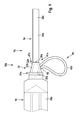
- Figure 1 shows an apparatus 38a which is intended for delivering a medical device 31a, like a lead 7a, and an agent 39a, like a radiocontrast, (see figure 2 ) during a vascular procedure, to a target location and into a human's body lumen or a vasculature, respectively (not shown).
- the apparatus 38a comprises an applicator 26a, embodied as a syringe 1a, a coupling 22a, embodied as a hub 2a, and a delivery device 29a with a tubular member 30a, embodied as a delivery shaft 3a.
- the coupling 22a has a base body 23a with a proximal end 24a and a distal end 27a, wherein the proximal end 24a is oriented towards an operator 40a (see figure 2 ). Moreover, the base body 23a has a recess 9a, which extends between the proximal end 24a and the distal end 27a and presents a through hole.
- the distal end 27a is embodied as a connecting region 28a for the delivery device 29a, wherein the connecting region 28a and thus the base body 23a, respectively, is integrally formed with the delivery device 29a. Therefore, a delivery sheath 5a is comprised of the shaft 3a and the hub 2a.
- the proximal end 24a is embodied as a connecting region 25a for the applicator 26a.
- the hub 2a is adapted to accept a male Luer fitting 6a of the Luer lock syringe 1a or other device (not shown) comprising a male Luer fitting. Therefore, the connecting region 25a at the proximal end 24a of the base body 23a has a Luer fitting 6a, which is realized by a friction fit of the male Luer fitting 6a of the syringe 1a in the recess 9a of the base body 23a.
- the coupling 22a or the hub 2a further comprises a handle 4a which is attached to or integrally formed with the base body 23a in a region 41a located axially between the connecting regions 25a, 28a.
- the handle 4a is embodied as a loop 42a and may be used to manipulate the delivery sheath 5a, for example, during removal from the body by means of slitting or splitting.
- FIG. 2 illustrates use of such a delivery sheath 5a wherein a Luer lock syringe 1a is connected to the hub 2a of the delivery sheath 5a.
- the Luer lock syringe 1a can be held in one hand of the operator 40a allowing simultaneous advancement or retraction, rotation, and/or infusion agent 39a or aspiration of blood.
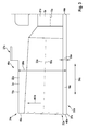
- Figure 3 exemplifies a cross-section through the hub 2a along the image plane in figure 1 .
- the hub 2a comprised the recess 9a capable of accepting a male Luer fitting 6a of the syringe 1a.
- the recess 9a may comply with standards describing Luer fittings or may be modified.
- the recess 9a is positioned in the hub 2a such that the base body 23a has a weak spot 33a which extends in axial direction 34a of the whole axial extension of the base body 23a and is intended for splitting or slitting of the base body 23a with a tool for splitting or slitting like a cutter (not shown).
- the weak spot 33a is embodied as a first or a thin wall segment 10a having a uniform width 35a in axial direction 34a over the whole axial extension of the base body 23a.
- the wall segment 10a of the hub 2a is substantially straight and/or has a substantially uniform thickness for ease of slitting.
- the slitting wall segment 10a may be relatively thin, e.g. compared to a second wall segment or the remaining wall segments of the hub 2a, likewise to facilitate easy slitting.
- the thin wall segment 10a abuts the recess 9a at least over a segment 43a of a circumference 37a of the recess 9a (not shown in detail, refer to figure 6 ).
- a downstream wall 44a of the delivery shaft 3 a has the same width as the thin wall segment 10a.
- a thicker wall segment 11 a is positioned diametrical opposite to the thin wall segment 10a.
- the thicker wall segment 11 a abuts the recess 9a at least over a segment 45a of the circumference 37a of the recess 9a (not shown in detail, refer to figure 6 ) and extends continuously in radial direction 46a along the axial direction 34a from the proximal end 24a to the distal end 27a of the base body 23a.
- the thicker wall segment 11 a provides a structural support for the base body 23a.
- the thin wall segment 10a is at the proximal end 24a about two times thinner than the thicker wall segment 11 a and at a region towards the distal end 27a about three times. Due to this and in order to facilitate slitting, a central axis 18a of the recess 9a is nonparallel in respect to a central axis 32a of the outer diameter 20a of the base body 23a or the hub 2a, respectively, and/or to the central axis 19a of the hub's 2a distal segment and/or the catheter shaft (not shown). In addition to the structural support of the nonparallel axes, they also accommodate Luer taper while maintaining the consistently thin slitting wall segment 10a.
- the recess 9a is not concentric with the outer diameter 20a of the hub 2a and/or with the distal lumen 21a of the hub 2a or catheter shaft (not shown). In other words, the recess 9a is positioned eccentrically from the outer diameter 20a of the base body 23a, wherein the outer diameter 20a refers to the region 41a located axially between the connecting regions 25a, 28a.
- the delivery sheath 5a or the delivery shaft 3a, respectively, with the introduced pacing lead is introduced into the right atrium to deliver the lead to the heart.
- a position of the delivery sheath 5 a within the heart may be manipulated with the handle 4a or the syringe 1 a by the operator 40a. Additionally, radiocontrast may be infused in order to identify and/or cannulate the coronary sinus and/or its tributaries.
- the delivery sheath 5 a with the coupling 22a and the delivery shaft 3a will be slit and the delivery sheath 5a will be removed leaving the pacing lead in place.
- the delivery sheath 5a, including hub 2a may be splittable (e.g. may be pealed away without the aid of a slitter or cutter) to facilitate its removal while leaving the lead in place.
- FIGS 4 to 15C eight alternative embodiments of the coupling 22a are shown. Components, features and functions that remain identical are in principle substantially denoted by the same reference characters. To distinguish between the embodiments, however, the letters a to i have been added to the reference characters of the embodiments. The following description is confined substantially to the differences from the embodiment in Figures 1 to 3 , wherein with regard to components, features and functions that remain identical reference may be made to the description of the embodiment in Figures 1 to 3 .
- FIG 4 illustrates an alternative embodiment of a delivery sheath 5b after removal of a Luer lock syringe (not shown).
- the delivery sheath 5b has a coupling 22b or hub 2b, respectively, with a base body 23b and a tubular member 30b or delivery shaft 3b arranged at a connecting region 28b of a distal end 25b of the base body 23b.
- the delivery device 29b and the base body 23b are integrally formed with each other.
- a medical device 31b or a pacing lead 7b is now inserted through the hub 2b of the delivery sheath 5b.
- a connecting region 25b at a proximal end 24b of the base body 23a has connecting means embodied as tabs 8b, which extend in a circumferential direction 36b of the base body 23b. Only one tab 8b for engaging a threaded Luer lock fitting, specifically a male Luer fitting 6b, of the syringe 1b is shown (see figure 8 ).
- the delivery sheath 5b including hub 2b may be slit using a slitter (not shown) in order to remove the delivery sheath 5b from the body while leaving the lead 7b in place.
- the delivery sheath 5b, including hub 2b may be splittable (e.g.
- the hub 2b or the base body 23b has a least a weak spot 33b embodied as a thin wall segment 10b to facilitate splitting (see figure 6 ). Alternatively a score line or other means to facilitate splitting are feasible.
- the weak spot 33b or the thin wall segment 10b extends in axial direction 34b of the base body 23b and has a uniform width 35b in axial direction 34b of the base body 23b (not shown).
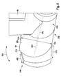
- Figures 5 is a perspective side view of the hub 2b including one tab 8b arranged at the proximal end 24b.
- a reach 47b of the tab 8b which extends from the side where the thin wall segment 10b is located is longer than a reach 48b which extends from a wall segment 11 b which is arranged opposite to the thin wall segment 10b Basically, one tab 8b would be sufficient for the Luer fitting.
- a handle 4b is molded to the base body 23b.
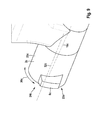
- Figure 6 is a view from the back of the hub 2b looking into a recess 9b or a top view of the proximal end 24b.
- the recess 9b extending between the proximal end 24b and the distal end 27b, is positioned eccentrically from an outer diameter 20b of the base body 23b (see figure 7a ) and a central axis 18b of the recess 9b is nonparallel in respect to a central axis 32b of the outer diameter 20b of the base body 23b (see also figure 5 ).
- the thin slitting wall segment 10b is seen below.
- a thicker wall segment 11 b provides structural support to the hub 2b and is positioned diametrical opposite to the thin wall segment 10b.
- the thin wall segment 10b and the thicker wall segment 11b are segments 43b, 45b which have roughly the same circumferential length 49b which is about a forth of the circumference 37b or about 90°.
- the hub 2b further comprises two tabs 8b adapted to engage the Luer lock syringe or other threaded Luer adapter (not shown).
- the threads or tabs 8b, 8b' extend over a part of an outer circumference 37b of the base body 23b or only partially around the circumference 37b of the proximal end 24b of the hub 2b so that the thin slitting wall segment 10b remains accessible for slitting.
- the two tabs 8b, 8b' are positioned diametrical towards each other and have roughly the same circumferential length 49b which is about a forth of the circumference 37b or about 90°.
- surfaces 50b of the tabs 8b, 8b' which face in circumferential direction 36b are embodied rounded down to lighten the engagement of the tabs 8b, 8b', which function as female Luer fitting 6b', with the male Luer fitting 6b.
- the general features of the tabs 8b, 8b' could also be applicable to the following embodiments in figures 9 , 10 , 11 , 13 and 15A - 15C .
- the tab/luer thread could extend about 270°, omitting only the thin slitting wall segment. In this particular design, there is an additional break in the tab opposite the thin slitting wall segment to provide clearance for installation of a screw which is used in this specific design.
- Figures 7 and 8 further describe the positional relationship of the recess (which is a female Luer fitting 6b') with respect to the threads/tabs 8b, 8b' and the outer diameter 20b of the hub 2b in order to facilitate slitting.
- Figure 7a shows the eccentric arrangement of the recess 9b in respect to the outer diameter 20b of the base body 23b. Due to this, the thin wall segment 10b could be realized.
- FIG 7b an arrangement according to a standard or state of the art device is shown.
- a recess R is arranged centrically in respect to an outer diameter OD, thus an inner diameter ID and the outer diameter OD are concentrically, both for simplicity of design as well as for flexibility in a location of threads or tabs T, T'. However, this results in a thick wall section S that is difficult to slit.
- FIG 8 shows the female Luer fitting 6b' with the tabs 8b, 8b' of the base body 23b engaged in a male Luer fitting 6b of a syringe 1b.
- the sealing surface of a Luer is only between an inner diameter 51b of the female Luer fitting 6b' or the recess 9b, respectively, and an outer diameter 52b of the male Luer (and not between an outer diameters 53a, 20b of the threads/tab 8b, 8b' and the base body 23b, respectively, of the female Luer fitting 6b' and an inner diameter 54b of a thread 55b of the male Luer fitting 6b), the Luer may still be constructed eccentrically such that the threads/tabs 8b, 8b' are concentric with the inner diameter 51b of the recess 9b, but not with the outer diameter 20b of the base body 23b.
- the threads/tabs 8b, 8b' will fit clearly within the thread 55b of the male Luer lock fitting 6b or syringe 1b and seal on the inner diameter 51b of the female Luer fitting 6b' even while leaving a gap 56b on the outside or between the circumference 37b of the base body 23b and the thread 55b of the male Luer filling 6b.
- outer contour 57b of the male Luer fitting 6b is concentric with the inner diameter 52b of the male Luer fitting 6b and with the outer diameter 52b of the male Luer fitting 6b and the inner diameter 51b of the female Luer fitting 6b, respectively, through center A.
- the outer diameter 20b of the base body 23b is not concentric with outer contour 57b of the male Luer fitting 6b or the inner diameter 51b of the female Luer fitting 6b' and with the outer diameter 52b of the male Luer fitting 6b, but has its own center at B which is opposite the thin wall segment 10b or the slitting side.
- Figure 9 illustrates a variation of the tab 8b that may be used for securing a threaded Luer adapter (not shown) to a coupling 22c or a hub 2c.
- the tab 8c is in respect to the Luer according to figure 5 reduced in its size in circumferential direction 36c of a base body 23c. Generally, more than one tab 8c could be practicable.
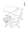
- Figure 10 illustrates a further variation on tabs 8b, 8c that may be used for securing a threaded Luer adapter (not shown) to a coupling 22d or a hub 2d.
- a connecting region 25d at a proximal end 24d of a base body 23d has at least two tabs 8d, 8d' which are arranged one after another in axial direction 34d of the base body 23d.
- an axial distance 58d of the tabs 8d, 8d' is matched to the width of the corresponding male Luer fitting (not shown). In this embodiment the distance 58d is equal to the axial extension 59d of one tab 8d, 8d'.
- the tabs 8d, 8d' have the same axial and circumferential lengths.
- the proximal tab 8d may have a tapered tip 60d in the region of a thicker wall 11d to facilitate the engagement of the Luer connection.
- more than two axially arranged tab 8d, 8d' could be feasible.
- an arrangement of another duplex of tab 8d, 8d' with is positioned diametrical towards the first duplex is possible.
- the hub may be adapted with alternative means for attaching to a syringe or other device (not shown).
- a syringe (not shown) and the hub may each be adapted with a snap fitting or other means (other than a threaded Luer fitting) for attaching to each other and enabling the hub to be manipulated by means of the syringe (not shown).
- the tab(s) may be omitted altogether, and the friction fit of male Luer fitting (not shown) in the recess (as shown in Figure 3 ) may be sufficient to enable the hub to be manipulated by means of its attachment to a syringe (not shown).
- FIG 11 illustrates a further alternative embodiment of a coupling 22e or hub 2e, respectively, which is a part of a delivery sheath 5e with a delivery device 29e or a tubular member 30 embodied as a delivery shaft 3e for delivering a medical device (not shown).
- the coupling 22e has a base body 23e with a recess 9e extending between a proximal end 24e and a distal end 27e of the base body 23e.
- the recess 9e is positioned eccentrically from an outer diameter 20e of the base body 23e and a central axis 18e of the recess 9e is nonparallel in respect to a central axis 32e of the outer diameter 20e of the base body 23e.
- the hub 2e further comprises a slittable hemostatic valve 12e, which is positioned at the distal end 27e of the base body 23e.
- the valve 12e is positioned distally to the recess 9e and is embodied as a one way valve, e.g. allowing infusion of agents into the body, but precluding leakage of blood (not shown).
- Tabs positioned at the proximal end 24e for connecting the hub 2e to a syringe are possible but not shown.
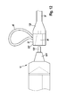
- Figure 12 illustrates a further alternative embodiment in which a coupling 22f or a hub 2f comprises a bidirectional valve 12f such that flow is precluded in either direction through the valve 12f.
- a syringe 1f further comprises a cannula 13f adapted to pass through the valve 12f when a distal end 61f of the syringe 1f is engaged in the recess 9f. Infusion and/or aspiration can take place through the valve 12f by way of the cannula 13f when it is crossing the valve 12f. However, when the cannula 13f is removed from the valve 12f, no flow is permitted.
- a compression, or syringe activated valve may also be used.
- Figure 13A illustrates a further alternative embodiment of a coupling 22g or a hub 2g which could be connected to a connecting region 62g of a delivery sheath 5g with a delivery device 29g or a delivery shaft 3g (for clearness connecting region 62g is not shown true to original in figure 13A ).
- a separate bypass tool 14g may be provided to adapt a syringe with a cannula to bypass the valve 12g. The bypass tool 14g would be removed along with the syringe prior to slitting.
- the coupling 22g is embodied as a bypass tool 14g and comprises a recess 9g for receiving the syringe or other male Luer fitting (not shown) and a cannula 13g or a bypass sheath 63g adapted to pass through the valve 12g.
- the bypass tool 14g may be secured against longitudinal movement by friction between the bypass sheath 63g and the hemostatic valve 12g. Also a side port of the delivery sheath 5g and a handle 4g is shown.
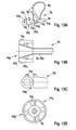
- Figure 13B depicts in more detail an embodiment of the connection region 62g of a proximal end 64g of the delivery sheath 5g with attachment means 15g (valve 12g not shown).
- the connection region 62g which could also function as a handle, is embodied as a cap 65g with outer pins 15g for the connection with the coupling 22g or a proximal end 66g of the bypass tool 14g, respectively.
- An alternative embodiment of a proximal end 64g' of an deliver sheath 5g' with only one pin 15g' is shown in figure 13C .
- FIG 13D an end-on view looking into the recess 9g of the bypass tool 14g is shown.
- a snap fitting may facilitate the connection of the bypass tool 14g to the connecting region 62g of the delivery sheath 5g.
- the bypass tool 14g has at its proximal end 66g an attachment means 16g for attaching the bypass tool 14g to the connecting region 62g and which is adapted to engage a corresponding feature or pins 15g, respectively, on the delivery sheath 5g.
- the bypass tool 14g may have a twist-lock mechanism 16g adapted to engage one or more features 15g on the proximal end 63g of the delivery sheath 5g.
- the attachment means 16g may have an inner knurl or structure (not shown) to lock on one or more pins 15g, located at the proximal end 64g of the delivery sheath 5g.
- the proximal end 66g of the bypass tool 14g further has an outer structure for locking on a syringe (not shown).
- the bypass tool 14g and the syringe may be secured against longitudinal movement by locking on the handle's pin 15g and by friction between bypass sheath 63g and the hemostatic valve 12g.
- the bypass tool 14g and the syringe may be secured against axial movement by locking on the handle's pin 15g.
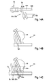
- FIG 14 illustrates a further alternative embodiment, in which a coupling 22h or hub 2h embodied as a bypass tool 14h comprises a recess 9h for receiving a syringe 1h or other male Luer fitting (not shown) and a cannula 13h or a bypass sheath 63h adapted to pass through a valve 12h (see figure 14A ).
- the bypass tool 14h further comprises an attachment means 16h adapted to engage a corresponding feature on a delivery sheath 5h shown in figure 14B .
- the bypass tool 14h comprising an attachment means 16h adapted to clip to a handle 4h of the delivery sheath 5h (see figure 14C ).
- Figures 15A to 15C illustrate in a first and a second side view as well as in a top view from a proximal end 24i an alternative embodiment where a delivery sheath 5i with a coupling 22i or hub 2i comprising an in-line side port 17i adapted to receive a syringe (not shown) is depicted.
- a delivery sheath 5i with a coupling 22i or hub 2i comprising an in-line side port 17i adapted to receive a syringe (not shown) is depicted.
- the in-line side port 17i extends in parallel to the base body 23i and discharges with a curved segment 67i into a delivery shaft 3i of the delivery device 29i downstream of a valve 12i which is positioned distally of a recess 9i of the coupling 22i (see figure 15A ).
- the in-line side port 17i is arranged at a side 68i of the base body 23i which is not slit during the procedure and/or which is circumferentially located between a thin wall segment 10i and a thicker wall segment 11i which abut the recess 9i. Tabs located at the proximal end 24i for connecting the hub 2i to the syringe are possible but not shown.
- the in-line side port 17i may be further adapted with conventional Luer locking mechanisms and does not need to be slit as part of the procedure.
Landscapes
- Health & Medical Sciences (AREA)
- Heart & Thoracic Surgery (AREA)
- Pulmonology (AREA)
- Engineering & Computer Science (AREA)
- Anesthesiology (AREA)
- Biomedical Technology (AREA)
- Hematology (AREA)
- Life Sciences & Earth Sciences (AREA)
- Animal Behavior & Ethology (AREA)
- General Health & Medical Sciences (AREA)
- Public Health (AREA)
- Veterinary Medicine (AREA)
- Infusion, Injection, And Reservoir Apparatuses (AREA)
- Radiation-Therapy Devices (AREA)
Abstract
Description
- The invention relates to a coupling according to the preamble of
claim 1. - When performing vascular procedures, it may be desirable to deliver diagnostic and/or therapeutic agents into the body. It may be further desirable to deliver such agents while manipulating the position of a delivery device within the body. For example, in the setting of cardiac lead delivery, it may be desirable to simultaneously infuse radiocontrast through a delivery sheath while manipulating the sheath within the chambers of the heart. It may be further desirable to subsequently deliver a pacing lead to the heart through the delivery sheath and then remove the delivery sheath to leave the pacing lead in place. As a specific example, a delivery sheath may be introduced into the right atrium. The position of the delivery sheath within the heart may be manipulated and radiocontrast infused in order to identify and/or cannulate the coronary sinus. Subsequently, the position of the delivery sheath within the coronary sinus may be manipulated and radiocontrast infused in order to identify and/or cannulate a coronary venous tributary to the coronary sinus. Subsequently, a left ventricular pacing lead may be delivered to the venous tributary through the delivery sheath, after which the delivery sheath may be split or slit and than removed leaving the pacing lead in place. Such delivery devices are known from
US 6,159,198 A andUS 2007/0293845 A1 . - A problem that arises is that the devices could have problems with easy slittability or splittability of the delivery device due to constructive properties of the device.
- The problem addressed by the invention is that of creating a coupling for a delivery device which has a slitting side with an improved slittability.
- The problem is solved according to the invention by the features of
claim 1. Favorable embodiments and advantages of the invention result from the further claims, the drawing, and the description. - The invention is directed to a coupling, in particular hub, with a base body having a proximal end, embodied as a connecting region for an applicator, and a distal end, embodied as connecting region for a delivery device with a tubular member for delivering a medical device into a part of an animal and/or human body, and having a recess located / extending between the proximal end and the distal end.
- It is provided that the recess is positioned eccentrically from an outer diameter of the base body and a central axis of the recess is nonparallel in respect to a central axis of the outer diameter of the base body. The embodiment according to the invention provides a coupling which could be easily removed after a placement of the medical device at an implantation site. Furthermore, the coupling could be constructed robustly and thus reliable.
- A "coupling" is intended to mean, in particular, a structure by which at least two components of an apparatus can be connected, wherein the apparatus is intended for delivering and/or extracting an implant, an instrument, a medical device and/or an agent during a medical procedure, like a vascular procedure, into or from an animal's and/or human's body part, cavity, recess, vessel, organ, and/or other lumen, like a gastrointestinal tract, a urogenital tract, a reproductive tract, a respiratory tract, a lymphatic system, and particularly a vasculature. The coupling process could be irreversible or preferably reversible. Moreover, the connection of the coupling with a component of the apparatus could be performed by any suitable connecting process by an adhesive bond, a friction fit, a snap fit, a form and/or force closure, like glueing, welding, crimping, screwing, knotting and/or any other process being feasible for a person skilled in the art. In this context, a "component" is intended to mean, in particular, an applicator, like an adapter, a syringe, a medical tube or a valve, or a delivery device, like a delivery shaft, a guide catheter, and/or other tubular member, to deliver a medical device, like a lead, a catheter and/or an electrode to a target location. Another component that appears reasonable to a person skilled in the art would also be feasible, however. Further, a "tubular member" is intended to mean, particularly, a structure with at least one tube.
- Furthermore, a "base body" in this context is intended to mean, in particular, a structure that substantially imparts a shape and/or form of the coupling. It is preferably manufactured out of plastic. Basically, it would also be feasible, however, for the base body to be composed at least partially of a biodegradable material. In this context, a "proximal end" is intended to mean, in particular, an end of the coupling or the base body, respectively, which, in the state of the medical procedure, is oriented towards an operator. Thus, a "distal end" is intended to mean, in particular, an end of the coupling or the base body, respectively, which, in the state of the medical procedure, is oriented away from the operator and/or toward the part of the animal's and/or human's body where the medical procedure takes place.
- In this case, a "connecting region" defines, in particular, a region, where a connection with another component took or can take place and/or which has at least a connecting means, like an electrical connector, a screw, a recesses, a groove, a ridge, a detent, a lug, a protrusion, a thread and/or any other means which is feasible for a person skilled in the art, is located and/or formed. Preferably the connecting region is adapted to accept a male Luer fitting. Furthermore, a "recess" in this context is intended to mean, in particular, a cavity, a hole and/or, in particular, a through hole. The phrase "extending between the proximal end and the distal end" is intended to mean, in particular, that the recess extends along an axial extension of the base body. In addition, an "outer diameter" of the base body is intended to mean, in particular, the greatest extension of the base body perpendicular to the central axis of the base body in an area or region of the base body located between the connecting regions at the proximal and the distal ends, thus the area has no connecting means. As a result, the radial width of a connecting means does not contribute to the outer diameter of the base body.
- Advantageously, a coupling is provided with base body which has at least a weak spot which extends at least in axial direction of the base body and is intended for splitting or slitting of the base body. In this context a "weak spot" is intended to mean, in particular, a thinned wall segment, a score line, a groove and/or other means to facilitate splitting or slitting. Other possibilities that are feasible are all embodiments that appear suitable to a person skilled in the art, such as a section of the base body manufactured of a material with less resilience and/or resistibility as the residual part of the base body. The weak spot extends along the whole axial extension of the base body. Moreover, the weak spot extends preferably in circumferential direction of the base body at least matched to a dimension and/or a width, respectively, of a tool for splitting or slitting, like a cutter. By means of the weak spot the opening of the base body and therefore, the removal of the delivery device could be performed easily and without disturbance of the location of the delivered medical device.
- Moreover, it is provided that the weak spot is embodied as a thin wall segment having a uniform width in least an axial direction of the base body. Possible is also a uniform width in circumferential direction as described in the next sentence. However, for the scope of the invention, the slittability of the hub, only the uniform width in axial direction is essential. Preferably the thin wall segment extends uniformly in circumferential direction of the base body with a width that is at least matched to the dimension and/or the width, respectively, of the tool for splitting or slitting. Moreover, the width of the connected downstream delivery shaft of the delivery device is matched and/or preferably equal to the width of the thin wall segment. A "thin wall segment" refers, in particular, to a segment or first segment of the base body which extends along a part of the circumference of the base body and partly abuts the recess and which is at least 1.2 times to 10 times thinner, preferably 1.5 times to 5 times thinner, and particularly advantageously 2 times to 3 times thinner than another, second segment of the base body, which extends along a part of the circumference of the base body, partly abuts the recess and is no part of a connection means. The term "uniform" should be understood as homogeneous, even and/or similar. Minimal deviations in the uniformity, such as an irregularity about ±1 % to 5 % from the width of the thin wall segment, do not alter the scope of the definition. Due to the thin wall segment the splitting and/or slitting can be realized without complications and especially gentle for structures and/or tissue located in proximity to the delivery device.
- Helpfully, in respect to the thin wall segment a thicker wall segment is positioned diametrical opposite to the thin wall segment and wherein the thicker wall segment provides a structural support for the base body. The width of the thicker wall segment preferably increases in radial direction of the recess from the proximal to the distal end of the base body. The thin and the thicker wall segments and/or the first and the second segment, respectively, could have the same circumferential length or different circumferential lengths. A slightly offset positioning of the thin and the thicker wall segments towards each other still renders the scope of the claim. The embodiment according to the invention provides profitably a solid coupling which has only minimal risk of collapsing during the medical procedure.
- Furthermore, it is advantageous when the connecting region at the proximal end of the base body has at least one Luer fitting. In this context, a "Luer fitting" is intended to mean, in particular, a male and preferably a female Luer fitting. It is therefore usefully possible to easily connect the coupling with devices embodied with state of the art Luer locks. As a result the coupling can be advantageously used with a great range of devices.
- In a further embodiment of the invention, the connecting region at the proximal end of the base body has at least one tab extending in a circumferential direction of the base body. The tab could extend along an inner circumference and/or an outer circumference of the base body. Moreover, the tab could extend over the whole inner and/or outer circumference of the base body, via which a robust snap fitting connection with an upstream component, like the applicator, could be achieved.
- It is furthermore provided that the connecting region at the proximal end of the base body has at least one tab extending over a part of the outer circumference of the base body. The tab is intended for engaging a threaded Luer lock fitting, specifically a male Luer fitting. Due to this mechanism the connection between the coupling and the upstream component could be realised both reversibly and securely.
- Furthermore, the connecting region at the proximal end of the base body has at least two tabs, which are positioned diametrical towards each other and are extending over a part of the outer circumference of the base body. Preferably, the tabs are intended to engage a threaded Luer lock fitting, specifically a male Luer fitting. Moreover, the tabs could have the same circumferential length or different lengths. A slight offset in positioning of the two tabs towards each other still renders the scope of the claim. Preferably, the weak spot is positioned centrically between the two tabs. By means of the embodiment according to the invention, a well-balanced connection could be maintained which assures a smooth action of the interaction partners.
- In addition, it is advantageous when the connecting region at the proximal end of the base body has at least two tabs which are arranged one after another in axial direction of the base body. Moreover, the two tabs could have the same circumferential length or different lengths. Further, an axial distance of the tabs is matched to the width of the corresponding fitting partner or the threaded part of the male Luer fitting, respectively. Thus, the threaded connection between the coupling and the upstream component could be performed tightly and safely.
- Further, providing at least one valve, which is positioned at the distal end of the base body, allows advantageously controlling a passage of media, like fluids, agents and/or medical devices through the coupling. Preferably the valve is embodied as hemostatic and/or splittable or slittable valve. In another embodiment of the invention it is provided, that the valve is embodied as a one-way valve, whereby an infusion of agents into the body could be allowed, but leakage of blood could be favourably precluded. Moreover, it is also provided that the valve could be embodied as a bidirectional valve, wherein the flow of media is beneficially precluded in either direction through the valve. Infusion and/or aspiration could preferably take place trough a cannula adapted to pass through the valve. Generally it is also possible that the valve is embodied as an adjustable, compression, or syringe activated valve and/or as any other valve being feasible for a person skilled in the art.
- Advantageously, the at least one valve is positioned distally in respect to the recess. Thus, the connecting region for the applicator is unaffected by the valve. Consequently, the connection function and the valve function could be arranged separately but at the same time positioned adjacent to each other. This, in turn, results in a space saving arrangement. Furthermore, it can be advantageous when the base body is integrally formed with the delivery device. In this context "integrally formed" is intended to mean, in particular, that the base body and the delivery device are molded out of one piece and/or that the base body and the delivery device could only be separate with loss of function for one of the parts. By means of the embodiment according to the invention resources, costs and assembly efforts can be reduced profitably.
- A good manageability can be achieved when the coupling has a handle which is attached to the base body. The handle is advantageously attached at the area between the connecting regions at the proximal and distal ends of the base body and/or integrally formed with the coupling. Moreover, it is embodied as a loop, whereby the handling could be increased and optimized.
- Thus, the invention provides desirably a single device that enables easy manipulation of the position and the infusion of diagnostic and/or therapeutic agents and which is subsequently capable of delivering a pacing lead and being removed by slitting or splitting.
- The invention is explained in the following in greater detail, as an example, with reference to an embodiment depicted in drawings. They show:
- Figure 1
- a coupling according to the invention attached to a Luer fitting of a syringe in a side view,
- Figure 2
- the coupling from
figure 1 with the syringe, - Figure 3
- a cross section through the coupling from
figure 1 , - Figure 4
- an alternative embodiment of a coupling with a partly inserted lead,
- Figure 5
- a perspective side view of the coupling from
figure 4 , - Figure 6
- a top view from a proximal end of the coupling from
figure 4 , - Figure 7A
- a schematic top view from a proximal end of the coupling from
figure 4 , - Figure 7B
- a schematic top view from a proximal end of a coupling according to the state of the art,
- Figure 8
- a schematic view of a Luer connection of the coupling from
figure 4 , - Figure 9
- a third embodiment of a coupling with a size reduced tab,
- Figure 10
- a forth embodiment of a coupling with to axially arranged tabs,
- Figure 11
- a fifth embodiment of a coupling with a one-way valve,
- Figure 12
- a sixth embodiment of a coupling with a bidirectional valve,
- Figure 13A
- a side view of a seventh embodiment of a coupling embodied as a bypass tool,
- Figure 13B
- a proximal end of a delivery sheath embodied as connecting region for the coupling of
figure 13A , - Figure 13C
- an alternative proximal end with only one pin in a top and a side view,
- Figure 13D
- an end-on view looking into a recess of the coupling from
figure 13A with an attachment means, - Figure 14A
- a side view of an eights embodiment of a coupling connected to a syringe embodied as a bypass tool with an attachment means,
- Figure 14B
- a delivery sheath with a connecting region for the coupling from
figure 14A , - Figure 14C
- an assembled arrangement of the coupling and the delivery device from
figures 14A and 14B , - Figure 15A
- a ninth embodiment of a coupling with a side-port,
- Figure 15B
- a side view of the coupling from
figure 15A and - Figure 15C
- a top view from a proximal end of the coupling from
figure 15A . - Elements that are functionally identical or similar-acting are labelled using the same reference numerals in the figures. The figures are schematic depictions of the invention. They do not depict specific parameters of the invention. Furthermore, the figures merely show typical embodiments of the invention and should not limit the invention to the embodiments shown.
- Regarding elements in a figure that are not described further, reference is made to the respective description of the elements in preceding figures to avoid unnecessary repetition.
-
Figure 1 shows anapparatus 38a which is intended for delivering a medical device 31a, like a lead 7a, and anagent 39a, like a radiocontrast, (seefigure 2 ) during a vascular procedure, to a target location and into a human's body lumen or a vasculature, respectively (not shown). Theapparatus 38a comprises anapplicator 26a, embodied as asyringe 1a, acoupling 22a, embodied as ahub 2a, and adelivery device 29a with atubular member 30a, embodied as adelivery shaft 3a. - The
coupling 22a has abase body 23a with aproximal end 24a and adistal end 27a, wherein theproximal end 24a is oriented towards anoperator 40a (seefigure 2 ). Moreover, thebase body 23a has a recess 9a, which extends between theproximal end 24a and thedistal end 27a and presents a through hole. Thedistal end 27a is embodied as a connectingregion 28a for thedelivery device 29a, wherein the connectingregion 28a and thus thebase body 23a, respectively, is integrally formed with thedelivery device 29a. Therefore, adelivery sheath 5a is comprised of theshaft 3a and thehub 2a. Theproximal end 24a is embodied as a connectingregion 25a for theapplicator 26a. Thehub 2a is adapted to accept a male Luer fitting 6a of theLuer lock syringe 1a or other device (not shown) comprising a male Luer fitting. Therefore, the connectingregion 25a at theproximal end 24a of thebase body 23a has a Luer fitting 6a, which is realized by a friction fit of the male Luer fitting 6a of thesyringe 1a in the recess 9a of thebase body 23a. - The
coupling 22a or thehub 2a, respectively, further comprises ahandle 4a which is attached to or integrally formed with thebase body 23a in aregion 41a located axially between the connectingregions handle 4a is embodied as aloop 42a and may be used to manipulate thedelivery sheath 5a, for example, during removal from the body by means of slitting or splitting. -
Figure 2 illustrates use of such adelivery sheath 5a wherein aLuer lock syringe 1a is connected to thehub 2a of thedelivery sheath 5a. TheLuer lock syringe 1a can be held in one hand of theoperator 40a allowing simultaneous advancement or retraction, rotation, and/orinfusion agent 39a or aspiration of blood. -
Figure 3 exemplifies a cross-section through thehub 2a along the image plane infigure 1 . Thehub 2a comprised the recess 9a capable of accepting a male Luer fitting 6a of thesyringe 1a. The recess 9a may comply with standards describing Luer fittings or may be modified. In this embodiment, the recess 9a is positioned in thehub 2a such that thebase body 23a has aweak spot 33a which extends inaxial direction 34a of the whole axial extension of thebase body 23a and is intended for splitting or slitting of thebase body 23a with a tool for splitting or slitting like a cutter (not shown). Theweak spot 33a is embodied as a first or athin wall segment 10a having auniform width 35a inaxial direction 34a over the whole axial extension of thebase body 23a. Thus, thewall segment 10a of thehub 2a is substantially straight and/or has a substantially uniform thickness for ease of slitting. The slittingwall segment 10a may be relatively thin, e.g. compared to a second wall segment or the remaining wall segments of thehub 2a, likewise to facilitate easy slitting. Thethin wall segment 10a abuts the recess 9a at least over asegment 43a of acircumference 37a of the recess 9a (not shown in detail, refer tofigure 6 ). Also for easy slitting adownstream wall 44a of thedelivery shaft 3 a has the same width as thethin wall segment 10a. - In respect to the
thin wall segment 10a athicker wall segment 11 a is positioned diametrical opposite to thethin wall segment 10a. Thethicker wall segment 11 a abuts the recess 9a at least over asegment 45a of thecircumference 37a of the recess 9a (not shown in detail, refer tofigure 6 ) and extends continuously inradial direction 46a along theaxial direction 34a from theproximal end 24a to thedistal end 27a of thebase body 23a. Thus, thethicker wall segment 11 a provides a structural support for thebase body 23a. Therefore, thethin wall segment 10a is at theproximal end 24a about two times thinner than thethicker wall segment 11 a and at a region towards thedistal end 27a about three times. Due to this and in order to facilitate slitting, acentral axis 18a of the recess 9a is nonparallel in respect to acentral axis 32a of theouter diameter 20a of thebase body 23a or thehub 2a, respectively, and/or to thecentral axis 19a of the hub's 2a distal segment and/or the catheter shaft (not shown). In addition to the structural support of the nonparallel axes, they also accommodate Luer taper while maintaining the consistently thinslitting wall segment 10a. - Additionally, the recess 9a is not concentric with the
outer diameter 20a of thehub 2a and/or with thedistal lumen 21a of thehub 2a or catheter shaft (not shown). In other words, the recess 9a is positioned eccentrically from theouter diameter 20a of thebase body 23a, wherein theouter diameter 20a refers to theregion 41a located axially between the connectingregions - During a vascular procedure the
delivery sheath 5a or thedelivery shaft 3a, respectively, with the introduced pacing lead is introduced into the right atrium to deliver the lead to the heart. A position of thedelivery sheath 5 a within the heart may be manipulated with thehandle 4a or thesyringe 1 a by theoperator 40a. Additionally, radiocontrast may be infused in order to identify and/or cannulate the coronary sinus and/or its tributaries. After the exact positioning of the electrodes and the lead 7a thedelivery sheath 5 a with thecoupling 22a and thedelivery shaft 3a will be slit and thedelivery sheath 5a will be removed leaving the pacing lead in place. Alternatively, thedelivery sheath 5a, includinghub 2a may be splittable (e.g. may be pealed away without the aid of a slitter or cutter) to facilitate its removal while leaving the lead in place. - In
figures 4 to 15C eight alternative embodiments of thecoupling 22a are shown. Components, features and functions that remain identical are in principle substantially denoted by the same reference characters. To distinguish between the embodiments, however, the letters a to i have been added to the reference characters of the embodiments. The following description is confined substantially to the differences from the embodiment inFigures 1 to 3 , wherein with regard to components, features and functions that remain identical reference may be made to the description of the embodiment inFigures 1 to 3 . -
Figure 4 illustrates an alternative embodiment of adelivery sheath 5b after removal of a Luer lock syringe (not shown). Thedelivery sheath 5b has acoupling 22b orhub 2b, respectively, with abase body 23b and atubular member 30b ordelivery shaft 3b arranged at a connectingregion 28b of adistal end 25b of thebase body 23b. Thus, the delivery device 29b and thebase body 23b are integrally formed with each other. Amedical device 31b or apacing lead 7b is now inserted through thehub 2b of thedelivery sheath 5b. A connectingregion 25b at aproximal end 24b of thebase body 23a has connecting means embodied astabs 8b, which extend in acircumferential direction 36b of thebase body 23b. Only onetab 8b for engaging a threaded Luer lock fitting, specifically a male Luer fitting 6b, of thesyringe 1b is shown (seefigure 8 ). After delivery of thelead 7b, thedelivery sheath 5b including hub 2b may be slit using a slitter (not shown) in order to remove thedelivery sheath 5b from the body while leaving thelead 7b in place. Alternatively, thedelivery sheath 5b, includinghub 2b may be splittable (e.g. may be pealed away without the aid of a slitter or cutter) to facilitate its removal while leaving thelead 7b in place. Thehub 2b or thebase body 23b has a least a weak spot 33b embodied as athin wall segment 10b to facilitate splitting (seefigure 6 ). Alternatively a score line or other means to facilitate splitting are feasible. The weak spot 33b or thethin wall segment 10b extends in axial direction 34b of thebase body 23b and has auniform width 35b in axial direction 34b of thebase body 23b (not shown). -
Figures 5 is a perspective side view of thehub 2b including onetab 8b arranged at theproximal end 24b. Areach 47b of thetab 8b which extends from the side where thethin wall segment 10b is located is longer than areach 48b which extends from awall segment 11 b which is arranged opposite to thethin wall segment 10b Basically, onetab 8b would be sufficient for the Luer fitting. In aregion 41b located between theends handle 4b is molded to thebase body 23b. -
Figure 6 is a view from the back of thehub 2b looking into arecess 9b or a top view of theproximal end 24b. Therecess 9b extending between theproximal end 24b and thedistal end 27b, is positioned eccentrically from anouter diameter 20b of thebase body 23b (seefigure 7a ) and acentral axis 18b of therecess 9b is nonparallel in respect to acentral axis 32b of theouter diameter 20b of thebase body 23b (see alsofigure 5 ). The thinslitting wall segment 10b is seen below. Athicker wall segment 11 b provides structural support to thehub 2b and is positioned diametrical opposite to thethin wall segment 10b. Thethin wall segment 10b and thethicker wall segment 11b aresegments circumferential length 49b which is about a forth of thecircumference 37b or about 90°. - The
hub 2b further comprises twotabs 8b adapted to engage the Luer lock syringe or other threaded Luer adapter (not shown). As depicted, the threads ortabs outer circumference 37b of thebase body 23b or only partially around thecircumference 37b of theproximal end 24b of thehub 2b so that the thinslitting wall segment 10b remains accessible for slitting. Moreover, the twotabs circumferential length 49b which is about a forth of thecircumference 37b or about 90°. Furthermore, surfaces 50b of thetabs circumferential direction 36b are embodied rounded down to lighten the engagement of thetabs tabs figures 9 ,10 ,11 ,13 and15A - 15C . In principal, the tab/luer thread could extend about 270°, omitting only the thin slitting wall segment. In this particular design, there is an additional break in the tab opposite the thin slitting wall segment to provide clearance for installation of a screw which is used in this specific design. -
Figures 7 and8 further describe the positional relationship of the recess (which is a female Luer fitting 6b') with respect to the threads/tabs outer diameter 20b of thehub 2b in order to facilitate slitting.Figure 7a shows the eccentric arrangement of therecess 9b in respect to theouter diameter 20b of thebase body 23b. Due to this, thethin wall segment 10b could be realized. Infigure 7b an arrangement according to a standard or state of the art device is shown. A recess R is arranged centrically in respect to an outer diameter OD, thus an inner diameter ID and the outer diameter OD are concentrically, both for simplicity of design as well as for flexibility in a location of threads or tabs T, T'. However, this results in a thick wall section S that is difficult to slit. -
Figure 8 shows the female Luer fitting 6b' with thetabs base body 23b engaged in a male Luer fitting 6b of asyringe 1b. As the sealing surface of a Luer is only between aninner diameter 51b of the female Luer fitting 6b' or therecess 9b, respectively, and anouter diameter 52b of the male Luer (and not between anouter diameters 53a, 20b of the threads/tab base body 23b, respectively, of the female Luer fitting 6b' and aninner diameter 54b of athread 55b of the male Luer fitting 6b), the Luer may still be constructed eccentrically such that the threads/tabs inner diameter 51b of therecess 9b, but not with theouter diameter 20b of thebase body 23b. Thus, the threads/tabs thread 55b of the male Luer lock fitting 6b orsyringe 1b and seal on theinner diameter 51b of the female Luer fitting 6b' even while leaving agap 56b on the outside or between thecircumference 37b of thebase body 23b and thethread 55b of the male Luer filling 6b. - Thus,
outer contour 57b of the male Luer fitting 6b is concentric with theinner diameter 52b of the male Luer fitting 6b and with theouter diameter 52b of the male Luer fitting 6b and theinner diameter 51b of the female Luer fitting 6b, respectively, through center A. Theouter diameter 20b of thebase body 23b is not concentric withouter contour 57b of the male Luer fitting 6b or theinner diameter 51b of the female Luer fitting 6b' and with theouter diameter 52b of the male Luer fitting 6b, but has its own center at B which is opposite thethin wall segment 10b or the slitting side. -
Figure 9 illustrates a variation of thetab 8b that may be used for securing a threaded Luer adapter (not shown) to acoupling 22c or ahub 2c. Thetab 8c is in respect to the Luer according tofigure 5 reduced in its size incircumferential direction 36c of abase body 23c. Generally, more than onetab 8c could be practicable. -
Figure 10 illustrates a further variation ontabs coupling 22d or ahub 2d. A connectingregion 25d at aproximal end 24d of abase body 23d has at least twotabs axial direction 34d of thebase body 23d. Further, anaxial distance 58d of thetabs distance 58d is equal to theaxial extension 59d of onetab tabs proximal tab 8d may have a taperedtip 60d in the region of athicker wall 11d to facilitate the engagement of the Luer connection. In general, more than two axially arrangedtab tab - In further embodiments (not shown) the hub may be adapted with alternative means for attaching to a syringe or other device (not shown). For example a syringe (not shown) and the hub may each be adapted with a snap fitting or other means (other than a threaded Luer fitting) for attaching to each other and enabling the hub to be manipulated by means of the syringe (not shown). Further alternatively, the tab(s) may be omitted altogether, and the friction fit of male Luer fitting (not shown) in the recess (as shown in
Figure 3 ) may be sufficient to enable the hub to be manipulated by means of its attachment to a syringe (not shown). -
Figure 11 illustrates a further alternative embodiment of acoupling 22e orhub 2e, respectively, which is a part of adelivery sheath 5e with adelivery device 29e or a tubular member 30 embodied as adelivery shaft 3e for delivering a medical device (not shown). Thecoupling 22e has abase body 23e with arecess 9e extending between aproximal end 24e and adistal end 27e of thebase body 23e. Moreover, therecess 9e is positioned eccentrically from anouter diameter 20e of thebase body 23e and acentral axis 18e of therecess 9e is nonparallel in respect to acentral axis 32e of theouter diameter 20e of thebase body 23e. Thehub 2e further comprises a slittablehemostatic valve 12e, which is positioned at thedistal end 27e of thebase body 23e. Thevalve 12e is positioned distally to therecess 9e and is embodied as a one way valve, e.g. allowing infusion of agents into the body, but precluding leakage of blood (not shown). Tabs positioned at theproximal end 24e for connecting thehub 2e to a syringe are possible but not shown. -
Figure 12 illustrates a further alternative embodiment in which acoupling 22f or ahub 2f comprises abidirectional valve 12f such that flow is precluded in either direction through thevalve 12f. Asyringe 1f further comprises acannula 13f adapted to pass through thevalve 12f when adistal end 61f of thesyringe 1f is engaged in the recess 9f. Infusion and/or aspiration can take place through thevalve 12f by way of thecannula 13f when it is crossing thevalve 12f. However, when thecannula 13f is removed from thevalve 12f, no flow is permitted. A compression, or syringe activated valve (not shown) may also be used. -
Figure 13A illustrates a further alternative embodiment of acoupling 22g or ahub 2g which could be connected to a connectingregion 62g of adelivery sheath 5g with adelivery device 29g or adelivery shaft 3g (forclearness connecting region 62g is not shown true to original infigure 13A ). Because syringes generally do not have a cannula such as could be used to by-pass abidirectional valve 12g, or alternatively a one-way valve with a small through hole, aseparate bypass tool 14g may be provided to adapt a syringe with a cannula to bypass thevalve 12g. Thebypass tool 14g would be removed along with the syringe prior to slitting. In this embodiment thecoupling 22g is embodied as abypass tool 14g and comprises arecess 9g for receiving the syringe or other male Luer fitting (not shown) and acannula 13g or abypass sheath 63g adapted to pass through thevalve 12g. Thebypass tool 14g may be secured against longitudinal movement by friction between thebypass sheath 63g and thehemostatic valve 12g. Also a side port of thedelivery sheath 5g and ahandle 4g is shown. -
Figure 13B depicts in more detail an embodiment of theconnection region 62g of aproximal end 64g of thedelivery sheath 5g with attachment means 15g (valve 12g not shown). Theconnection region 62g, which could also function as a handle, is embodied as acap 65g withouter pins 15g for the connection with thecoupling 22g or aproximal end 66g of thebypass tool 14g, respectively. An alternative embodiment of aproximal end 64g' of an deliversheath 5g' with only onepin 15g' is shown infigure 13C . - In
figure 13D an end-on view looking into therecess 9g of thebypass tool 14g is shown. As an example, a snap fitting may facilitate the connection of thebypass tool 14g to the connectingregion 62g of thedelivery sheath 5g. ,Thebypass tool 14g has at itsproximal end 66g an attachment means 16g for attaching thebypass tool 14g to the connectingregion 62g and which is adapted to engage a corresponding feature or pins 15g, respectively, on thedelivery sheath 5g. For example thebypass tool 14g may have a twist-lock mechanism 16g adapted to engage one ormore features 15g on theproximal end 63g of thedelivery sheath 5g. The attachment means 16g may have an inner knurl or structure (not shown) to lock on one ormore pins 15g, located at theproximal end 64g of thedelivery sheath 5g. Alternatively, or in addition to, it is possible, that theproximal end 66g of thebypass tool 14g further has an outer structure for locking on a syringe (not shown). Thebypass tool 14g and the syringe may be secured against longitudinal movement by locking on the handle'spin 15g and by friction betweenbypass sheath 63g and thehemostatic valve 12g. Thebypass tool 14g and the syringe may be secured against axial movement by locking on the handle'spin 15g. -
Figure 14 illustrates a further alternative embodiment, in which acoupling 22h orhub 2h embodied as abypass tool 14h comprises arecess 9h for receiving asyringe 1h or other male Luer fitting (not shown) and acannula 13h or abypass sheath 63h adapted to pass through avalve 12h (seefigure 14A ). Thebypass tool 14h further comprises an attachment means 16h adapted to engage a corresponding feature on adelivery sheath 5h shown infigure 14B . For example thebypass tool 14h comprising an attachment means 16h adapted to clip to ahandle 4h of thedelivery sheath 5h (seefigure 14C ). -
Figures 15A to 15C illustrate in a first and a second side view as well as in a top view from aproximal end 24i an alternative embodiment where adelivery sheath 5i with acoupling 22i orhub 2i comprising an in-line side port 17i adapted to receive a syringe (not shown) is depicted. Starting at theproximal end 24i of abase body 23i of thehub 2i the in-line side port 17i extends in parallel to thebase body 23i and discharges with acurved segment 67i into adelivery shaft 3i of thedelivery device 29i downstream of avalve 12i which is positioned distally of arecess 9i of thecoupling 22i (seefigure 15A ). As could especially be seen infigure 15C the in-line side port 17i is arranged at aside 68i of thebase body 23i which is not slit during the procedure and/or which is circumferentially located between athin wall segment 10i and athicker wall segment 11i which abut therecess 9i. Tabs located at theproximal end 24i for connecting thehub 2i to the syringe are possible but not shown. The in-line side port 17i may be further adapted with conventional Luer locking mechanisms and does not need to be slit as part of the procedure. -
- 1
- syringe
- 2
- hub
- 3
- shaft
- 4
- handle
- 5
- sheath
- 6
- Luer fitting
- 7
- lead
- 8
- tab
- 9
- recess
- 10
- segment
- 11
- segment
- 12
- valve
- 13
- cannula
- 14
- bypass
- 15
- feature / pin
- 16
- attachment means
- 17
- side port
- 18
- axis
- 19
- axis
- 20
- diameter
- 21
- lumen
- 22
- coupling
- 23
- base body
- 24
- proximal end
- 25
- connecting region
- 26
- applicator
- 27
- distal end
- 28
- connecting region
- 29
- delivery device
- 30
- tubular member
- 31
- medical device
- 32
- axis
- 33
- weak spot
- 34
- axial direction
- 35
- width
- 36
- circumferential direction
- 37
- outer circumference
- 38
- apparatus
- 39
- agent
- 40
- operator
- 41
- region
- 42
- loop
- 43
- segment
- 44
- wall
- 45
- segment
- 46
- radial direction
- 47
- reach
- 48
- reach
- 49
- circumferential length
- 50
- surface
- 51
- inner diameter recess
- 52
- outer diameter male
- 53
- outer diameter female
- 54
- inner diameter male
- 55
- thread
- 56
- gab
- 57
- contour
- 58
- distance
- 59
- extension
- 60
- tip
- 61
- end
- 62
- connecting region
- 63
- sheath
- 64
- end
- 65
- cap
- 66
- end
- 67
- segment
- 68
- side
- A
- center
- B
- center
- ID
- inner diameter
- OD
- outer diameter
- R
- recess
- S
- wall section
- T
- tab
Claims (14)
- Coupling, in particular hub (2 a-i), with a base body (23 a-i) having a proximal end (24 a-i), embodied as a connecting region (25 a-i) for an applicator (26 a-i), and a distal end (27 a-i), embodied as connecting region (28 a-i) for a delivery device (29 a-i) with a tubular member (30 a-i) for delivering a medical device (31 a-i) into a part of an animal and/or human body, and having a recess (9 a-i) extending between the proximal end (24 a-i) and the distal end (27 a-i), wherein the recess (9 a-i) is positioned eccentrically from an outer diameter (20 a-i) of the base body (23 a-i) and a central axis (18 a-i) of the recess (9 a-i) is nonparallel in respect to a central axis (32 a-i) of the outer diameter (20 a-i) of the base body (23 a-i).
- The coupling according to claim 1, wherein the base body (23 a-i) has at least a weak spot (33 a-i) which extends at least in axial direction (34 a-i) of the base body (23 a-i) and is intended for splitting or slitting of the base body (23 a-i).
- The coupling according to claim 2, wherein the weak spot (32 a-i) is embodied as a thin wall segment (10 a-i) having a uniform width (35 a-i) in least an axial direction (34 a-i) of the base body (23 a-i).
- The coupling according to claim 3, wherein in respect to the thin wall segment (10 a-i) a thicker wall segment (11 a-i) is positioned diametrical opposite to the thin wall segment (10 a-i) and wherein the thicker wall segment (11 a-i) provides a structural support for the base body (23 a-i).
- The coupling according to one of the preceding claims, wherein the connecting region (25 a-i) at the proximal end (24 a-i) of the base body (23 a-i) has at least one Luer fitting (6 a-i').
- The coupling according to one of the preceding claims, wherein the connecting region (25 b-e, i) at the proximal end (24 b-e, i) of the base body (23 b-e, i) has at least one tab (8 b-e, i) extending in a circumferential direction (36 a-i) of the base body (23 b-e, i).
- The coupling according to one of the preceding claims, wherein the connecting region (25 b-e, i) at the proximal end (24 b-e, i) of the base body (23 b-e, i) has at least one tab (8 b-e, i) extending over a part of the outer circumference (37 b-e, i) of the base body (23 b-e, i).
- The coupling according to one of the preceding claims, wherein the connecting region (25 b-e, i) at the proximal end (24 b-e, i) of the base body (23 b-e, i) has at least two tabs (8 b-e, i, 8 b-e, i'), which are positioned diametrical towards each other and are extending over a part of the outer circumference (37 b-e, i) of the base body (23 b-e, i).
- The coupling according to one of the preceding claims, wherein the connecting region (25 d) at the proximal end (24 d) of the base body (23 d) has at least two tabs (8 d, 8 d') which are arranged one after another in axial direction (34 d) of the base body (23 d).
- The coupling according to one of the preceding claims, wherein at least one valve (12 e-i) is positioned at the distal end (27 e-i) of the base body (23 e-i).
- The coupling according to claim 10, wherein the at least one valve (12 e-i) is positioned distally in respect to the recess (9 e-i).
- The coupling according to one of the preceding claims, wherein the base body (23 a-e, i) is integrally formed with the delivery device (29 a-e, i).
- The coupling according to one of the preceding claims, wherein a handle (4 a-i) is attached to the base body (23 a-i).
- A method for introducing a medical device (31 a-i) into an animal and/or human body comprising the following steps:- manipulating a delivery device (29 a-i) for the medical device (31 a-i) with an applicator (26 a-i), wherein the delivery device (29 a-i) is attached to the applicator (26 a-i) via a coupling (22 a-i) according to claim 1,- removing the applicator (26 a-i) from the coupling (22 a-i),- placing the medical device (31 a-i) through the coupling (22 a-i) and the delivery device (29 a-i) at an implantation side, and- slitting the coupling (22 a-i) and the delivery device (29 a-i) for removal from the animal and/or human body.
Applications Claiming Priority (1)
| Application Number | Priority Date | Filing Date | Title |
|---|---|---|---|
| US32887010P | 2010-04-28 | 2010-04-28 |
Publications (3)
| Publication Number | Publication Date |
|---|---|
| EP2383010A2 true EP2383010A2 (en) | 2011-11-02 |
| EP2383010A3 EP2383010A3 (en) | 2012-08-22 |
| EP2383010B1 EP2383010B1 (en) | 2017-05-31 |
Family
ID=44146996
Family Applications (1)
| Application Number | Title | Priority Date | Filing Date |
|---|---|---|---|
| EP11161561.3A Active EP2383010B1 (en) | 2010-04-28 | 2011-04-07 | Coupling |
Country Status (2)
| Country | Link |
|---|---|
| US (1) | US9393400B2 (en) |
| EP (1) | EP2383010B1 (en) |
Cited By (1)
| Publication number | Priority date | Publication date | Assignee | Title |
|---|---|---|---|---|
| CN110248585A (en) * | 2016-10-07 | 2019-09-17 | 博迪维仁医疗有限公司 | Device and its application method used in intervention and surgical operation |
Families Citing this family (2)
| Publication number | Priority date | Publication date | Assignee | Title |
|---|---|---|---|---|
| US8740864B2 (en) * | 2005-11-17 | 2014-06-03 | Becton, Dickinson And Company | Patient fluid line access valve antimicrobial cap/cleaner |
| US9381030B2 (en) * | 2010-07-15 | 2016-07-05 | Nuvectra Corporation | Tunneling tool for implantable leads |
Family Cites Families (6)
| Publication number | Priority date | Publication date | Assignee | Title |
|---|---|---|---|---|
| US5947954A (en) * | 1997-11-19 | 1999-09-07 | Creative Plastic Technology, Llc | Needle-less luer actuated medical connector |
| US6159198A (en) | 1998-07-16 | 2000-12-12 | Medtronic, Inc. | Introducer system |
| WO2001002047A1 (en) | 1999-07-06 | 2001-01-11 | Medtronic, Inc. | Catheter introducer system |
| AU2741801A (en) * | 1999-12-30 | 2001-07-16 | Cook Vascular Incorporated | Splittable medical valve |
| US20040267202A1 (en) * | 2003-06-26 | 2004-12-30 | Potter Daniel J. | Tearable hemostasis valve and splittable sheath |
| US7824375B2 (en) | 2008-10-09 | 2010-11-02 | Pacesetter, Inc. | Slittable delivery device for the delivery of a cardiac surgical device |
-
2011
- 2011-01-27 US US13/015,097 patent/US9393400B2/en active Active
- 2011-04-07 EP EP11161561.3A patent/EP2383010B1/en active Active
Non-Patent Citations (1)
| Title |
|---|
| None |
Cited By (1)
| Publication number | Priority date | Publication date | Assignee | Title |
|---|---|---|---|---|
| CN110248585A (en) * | 2016-10-07 | 2019-09-17 | 博迪维仁医疗有限公司 | Device and its application method used in intervention and surgical operation |
Also Published As
| Publication number | Publication date |
|---|---|
| US9393400B2 (en) | 2016-07-19 |
| EP2383010A3 (en) | 2012-08-22 |
| US20110270268A1 (en) | 2011-11-03 |
| EP2383010B1 (en) | 2017-05-31 |
Similar Documents
| Publication | Publication Date | Title |
|---|---|---|
| JP7304890B2 (en) | Multi-diameter catheters and related devices and methods | |
| EP1651299B1 (en) | Catheter tunneler adapter | |
| CN217430637U (en) | Needle and system for accessing the vascular system of a patient | |
| EP3470106B1 (en) | Interlocking needle hub and catheter hub actuator to increase rigidity of iv catheter assembly | |
| CA2600841C (en) | Catheter with larger diameter proximal end portion | |
| US9669189B2 (en) | Medical delivery systems and apparatus | |
| JP2022526808A (en) | Vascular access device with fluid permeable structure and related devices | |
| CN106422031B (en) | Guide wire luer hub | |
| US20060015130A1 (en) | Catheter tunneler adapter | |
| US8690859B2 (en) | Catheter apparatus | |
| US20110313399A1 (en) | Intravenous cannula | |
| CN219022904U (en) | Introducer assembly and introducer adapter | |
| CN219290384U (en) | Vascular access device | |
| AU2021228640B2 (en) | Syringe with snap-in enteral connection feature | |
| EP2383010B1 (en) | Coupling | |
| CN216258585U (en) | Syringe | |
| US12440651B2 (en) | Catheter assembly | |
| CN114247030A (en) | Convertible catheter sheath | |
| US20240165385A1 (en) | Intraosseous infusion ports and methods of use | |
| US20240269432A1 (en) | Blood Draw Connector for Open Peripheral Intravenous Catheters | |
| CA3167182C (en) | Syringe with snap-in enteral connection feature |
Legal Events
| Date | Code | Title | Description |
|---|---|---|---|
| AK | Designated contracting states |
Kind code of ref document: A2 Designated state(s): AL AT BE BG CH CY CZ DE DK EE ES FI FR GB GR HR HU IE IS IT LI LT LU LV MC MK MT NL NO PL PT RO RS SE SI SK SM TR |
|
| AX | Request for extension of the european patent |
Extension state: BA ME |
|
| PUAI | Public reference made under article 153(3) epc to a published international application that has entered the european phase |
Free format text: ORIGINAL CODE: 0009012 |
|
| PUAL | Search report despatched |
Free format text: ORIGINAL CODE: 0009013 |
|
| AK | Designated contracting states |
Kind code of ref document: A3 Designated state(s): AL AT BE BG CH CY CZ DE DK EE ES FI FR GB GR HR HU IE IS IT LI LT LU LV MC MK MT NL NO PL PT RO RS SE SI SK SM TR |
|
| AX | Request for extension of the european patent |
Extension state: BA ME |
|
| RIC1 | Information provided on ipc code assigned before grant |
Ipc: A61M 39/10 20060101ALI20120717BHEP Ipc: A61M 25/06 20060101AFI20120717BHEP |
|
| 17P | Request for examination filed |
Effective date: 20130220 |
|
| 17Q | First examination report despatched |
Effective date: 20130517 |
|
| REG | Reference to a national code |
Ref country code: DE Ref legal event code: R079 Ref document number: 602011038274 Country of ref document: DE Free format text: PREVIOUS MAIN CLASS: A61M0025060000 Ipc: A61M0025000000 |
|
| GRAP | Despatch of communication of intention to grant a patent |
Free format text: ORIGINAL CODE: EPIDOSNIGR1 |
|
| RIC1 | Information provided on ipc code assigned before grant |
Ipc: A61M 25/06 20060101ALI20161114BHEP Ipc: A61M 39/10 20060101ALI20161114BHEP Ipc: A61M 25/00 20060101AFI20161114BHEP |
|
| INTG | Intention to grant announced |
Effective date: 20161206 |
|
| GRAS | Grant fee paid |
Free format text: ORIGINAL CODE: EPIDOSNIGR3 |
|
| GRAA | (expected) grant |
Free format text: ORIGINAL CODE: 0009210 |
|
| AK | Designated contracting states |
Kind code of ref document: B1 Designated state(s): AL AT BE BG CH CY CZ DE DK EE ES FI FR GB GR HR HU IE IS IT LI LT LU LV MC MK MT NL NO PL PT RO RS SE SI SK SM TR |
|
| REG | Reference to a national code |
Ref country code: CH Ref legal event code: EP Ref country code: GB Ref legal event code: FG4D |
|
| REG | Reference to a national code |
Ref country code: AT Ref legal event code: REF Ref document number: 896872 Country of ref document: AT Kind code of ref document: T Effective date: 20170615 |
|
| REG | Reference to a national code |
Ref country code: IE Ref legal event code: FG4D |
|
| REG | Reference to a national code |
Ref country code: DE Ref legal event code: R096 Ref document number: 602011038274 Country of ref document: DE |
|
| REG | Reference to a national code |
Ref country code: NL Ref legal event code: MP Effective date: 20170531 |
|
| REG | Reference to a national code |
Ref country code: LT Ref legal event code: MG4D |
|
| REG | Reference to a national code |
Ref country code: AT Ref legal event code: MK05 Ref document number: 896872 Country of ref document: AT Kind code of ref document: T Effective date: 20170531 |
|
| PG25 | Lapsed in a contracting state [announced via postgrant information from national office to epo] |
Ref country code: AT Free format text: LAPSE BECAUSE OF FAILURE TO SUBMIT A TRANSLATION OF THE DESCRIPTION OR TO PAY THE FEE WITHIN THE PRESCRIBED TIME-LIMIT Effective date: 20170531 Ref country code: HR Free format text: LAPSE BECAUSE OF FAILURE TO SUBMIT A TRANSLATION OF THE DESCRIPTION OR TO PAY THE FEE WITHIN THE PRESCRIBED TIME-LIMIT Effective date: 20170531 Ref country code: ES Free format text: LAPSE BECAUSE OF FAILURE TO SUBMIT A TRANSLATION OF THE DESCRIPTION OR TO PAY THE FEE WITHIN THE PRESCRIBED TIME-LIMIT Effective date: 20170531 Ref country code: GR Free format text: LAPSE BECAUSE OF FAILURE TO SUBMIT A TRANSLATION OF THE DESCRIPTION OR TO PAY THE FEE WITHIN THE PRESCRIBED TIME-LIMIT Effective date: 20170901 Ref country code: LT Free format text: LAPSE BECAUSE OF FAILURE TO SUBMIT A TRANSLATION OF THE DESCRIPTION OR TO PAY THE FEE WITHIN THE PRESCRIBED TIME-LIMIT Effective date: 20170531 Ref country code: FI Free format text: LAPSE BECAUSE OF FAILURE TO SUBMIT A TRANSLATION OF THE DESCRIPTION OR TO PAY THE FEE WITHIN THE PRESCRIBED TIME-LIMIT Effective date: 20170531 Ref country code: NO Free format text: LAPSE BECAUSE OF FAILURE TO SUBMIT A TRANSLATION OF THE DESCRIPTION OR TO PAY THE FEE WITHIN THE PRESCRIBED TIME-LIMIT Effective date: 20170831 |
|
| PG25 | Lapsed in a contracting state [announced via postgrant information from national office to epo] |
Ref country code: NL Free format text: LAPSE BECAUSE OF FAILURE TO SUBMIT A TRANSLATION OF THE DESCRIPTION OR TO PAY THE FEE WITHIN THE PRESCRIBED TIME-LIMIT Effective date: 20170531 Ref country code: BG Free format text: LAPSE BECAUSE OF FAILURE TO SUBMIT A TRANSLATION OF THE DESCRIPTION OR TO PAY THE FEE WITHIN THE PRESCRIBED TIME-LIMIT Effective date: 20170831 Ref country code: LV Free format text: LAPSE BECAUSE OF FAILURE TO SUBMIT A TRANSLATION OF THE DESCRIPTION OR TO PAY THE FEE WITHIN THE PRESCRIBED TIME-LIMIT Effective date: 20170531 Ref country code: RS Free format text: LAPSE BECAUSE OF FAILURE TO SUBMIT A TRANSLATION OF THE DESCRIPTION OR TO PAY THE FEE WITHIN THE PRESCRIBED TIME-LIMIT Effective date: 20170531 Ref country code: SE Free format text: LAPSE BECAUSE OF FAILURE TO SUBMIT A TRANSLATION OF THE DESCRIPTION OR TO PAY THE FEE WITHIN THE PRESCRIBED TIME-LIMIT Effective date: 20170531 Ref country code: IS Free format text: LAPSE BECAUSE OF FAILURE TO SUBMIT A TRANSLATION OF THE DESCRIPTION OR TO PAY THE FEE WITHIN THE PRESCRIBED TIME-LIMIT Effective date: 20170930 |
|
| PG25 | Lapsed in a contracting state [announced via postgrant information from national office to epo] |
Ref country code: SK Free format text: LAPSE BECAUSE OF FAILURE TO SUBMIT A TRANSLATION OF THE DESCRIPTION OR TO PAY THE FEE WITHIN THE PRESCRIBED TIME-LIMIT Effective date: 20170531 Ref country code: RO Free format text: LAPSE BECAUSE OF FAILURE TO SUBMIT A TRANSLATION OF THE DESCRIPTION OR TO PAY THE FEE WITHIN THE PRESCRIBED TIME-LIMIT Effective date: 20170531 Ref country code: CZ Free format text: LAPSE BECAUSE OF FAILURE TO SUBMIT A TRANSLATION OF THE DESCRIPTION OR TO PAY THE FEE WITHIN THE PRESCRIBED TIME-LIMIT Effective date: 20170531 Ref country code: EE Free format text: LAPSE BECAUSE OF FAILURE TO SUBMIT A TRANSLATION OF THE DESCRIPTION OR TO PAY THE FEE WITHIN THE PRESCRIBED TIME-LIMIT Effective date: 20170531 Ref country code: DK Free format text: LAPSE BECAUSE OF FAILURE TO SUBMIT A TRANSLATION OF THE DESCRIPTION OR TO PAY THE FEE WITHIN THE PRESCRIBED TIME-LIMIT Effective date: 20170531 |
|
| PG25 | Lapsed in a contracting state [announced via postgrant information from national office to epo] |
Ref country code: PL Free format text: LAPSE BECAUSE OF FAILURE TO SUBMIT A TRANSLATION OF THE DESCRIPTION OR TO PAY THE FEE WITHIN THE PRESCRIBED TIME-LIMIT Effective date: 20170531 Ref country code: SM Free format text: LAPSE BECAUSE OF FAILURE TO SUBMIT A TRANSLATION OF THE DESCRIPTION OR TO PAY THE FEE WITHIN THE PRESCRIBED TIME-LIMIT Effective date: 20170531 Ref country code: IT Free format text: LAPSE BECAUSE OF FAILURE TO SUBMIT A TRANSLATION OF THE DESCRIPTION OR TO PAY THE FEE WITHIN THE PRESCRIBED TIME-LIMIT Effective date: 20170531 |
|
| REG | Reference to a national code |
Ref country code: DE Ref legal event code: R097 Ref document number: 602011038274 Country of ref document: DE |
|
| PLBE | No opposition filed within time limit |
Free format text: ORIGINAL CODE: 0009261 |
|
| STAA | Information on the status of an ep patent application or granted ep patent |
Free format text: STATUS: NO OPPOSITION FILED WITHIN TIME LIMIT |
|
| 26N | No opposition filed |
Effective date: 20180301 |
|
| PG25 | Lapsed in a contracting state [announced via postgrant information from national office to epo] |
Ref country code: SI Free format text: LAPSE BECAUSE OF FAILURE TO SUBMIT A TRANSLATION OF THE DESCRIPTION OR TO PAY THE FEE WITHIN THE PRESCRIBED TIME-LIMIT Effective date: 20170531 |
|
| PG25 | Lapsed in a contracting state [announced via postgrant information from national office to epo] |
Ref country code: MC Free format text: LAPSE BECAUSE OF FAILURE TO SUBMIT A TRANSLATION OF THE DESCRIPTION OR TO PAY THE FEE WITHIN THE PRESCRIBED TIME-LIMIT Effective date: 20170531 |
|
| REG | Reference to a national code |
Ref country code: BE Ref legal event code: MM Effective date: 20180430 |
|
| GBPC | Gb: european patent ceased through non-payment of renewal fee |
Effective date: 20180407 |
|
| PG25 | Lapsed in a contracting state [announced via postgrant information from national office to epo] |
Ref country code: LU Free format text: LAPSE BECAUSE OF NON-PAYMENT OF DUE FEES Effective date: 20180407 |
|
| PG25 | Lapsed in a contracting state [announced via postgrant information from national office to epo] |
Ref country code: BE Free format text: LAPSE BECAUSE OF NON-PAYMENT OF DUE FEES Effective date: 20180430 Ref country code: GB Free format text: LAPSE BECAUSE OF NON-PAYMENT OF DUE FEES Effective date: 20180407 |
|
| PG25 | Lapsed in a contracting state [announced via postgrant information from national office to epo] |
Ref country code: FR Free format text: LAPSE BECAUSE OF NON-PAYMENT OF DUE FEES Effective date: 20180430 |
|
| PG25 | Lapsed in a contracting state [announced via postgrant information from national office to epo] |
Ref country code: MT Free format text: LAPSE BECAUSE OF NON-PAYMENT OF DUE FEES Effective date: 20180407 |
|
| PG25 | Lapsed in a contracting state [announced via postgrant information from national office to epo] |
Ref country code: TR Free format text: LAPSE BECAUSE OF FAILURE TO SUBMIT A TRANSLATION OF THE DESCRIPTION OR TO PAY THE FEE WITHIN THE PRESCRIBED TIME-LIMIT Effective date: 20170531 |
|
| PG25 | Lapsed in a contracting state [announced via postgrant information from national office to epo] |
Ref country code: PT Free format text: LAPSE BECAUSE OF FAILURE TO SUBMIT A TRANSLATION OF THE DESCRIPTION OR TO PAY THE FEE WITHIN THE PRESCRIBED TIME-LIMIT Effective date: 20170531 Ref country code: HU Free format text: LAPSE BECAUSE OF FAILURE TO SUBMIT A TRANSLATION OF THE DESCRIPTION OR TO PAY THE FEE WITHIN THE PRESCRIBED TIME-LIMIT; INVALID AB INITIO Effective date: 20110407 |
|
| PG25 | Lapsed in a contracting state [announced via postgrant information from national office to epo] |
Ref country code: CY Free format text: LAPSE BECAUSE OF FAILURE TO SUBMIT A TRANSLATION OF THE DESCRIPTION OR TO PAY THE FEE WITHIN THE PRESCRIBED TIME-LIMIT Effective date: 20170531 Ref country code: MK Free format text: LAPSE BECAUSE OF NON-PAYMENT OF DUE FEES Effective date: 20170531 |
|
| PG25 | Lapsed in a contracting state [announced via postgrant information from national office to epo] |
Ref country code: AL Free format text: LAPSE BECAUSE OF FAILURE TO SUBMIT A TRANSLATION OF THE DESCRIPTION OR TO PAY THE FEE WITHIN THE PRESCRIBED TIME-LIMIT Effective date: 20170531 |
|
| P01 | Opt-out of the competence of the unified patent court (upc) registered |
Effective date: 20230607 |
|
| REG | Reference to a national code |
Ref country code: CH Ref legal event code: U11 Free format text: ST27 STATUS EVENT CODE: U-0-0-U10-U11 (AS PROVIDED BY THE NATIONAL OFFICE) Effective date: 20260501 |
|
| PGFP | Annual fee paid to national office [announced via postgrant information from national office to epo] |
Ref country code: DE Payment date: 20260420 Year of fee payment: 16 |
|
| PGFP | Annual fee paid to national office [announced via postgrant information from national office to epo] |
Ref country code: CH Payment date: 20260501 Year of fee payment: 16 Ref country code: IE Payment date: 20260423 Year of fee payment: 16 |