EP2381860B1 - Medical device with pivotable jaws - Google Patents
Medical device with pivotable jaws Download PDFInfo
- Publication number
- EP2381860B1 EP2381860B1 EP09796258.3A EP09796258A EP2381860B1 EP 2381860 B1 EP2381860 B1 EP 2381860B1 EP 09796258 A EP09796258 A EP 09796258A EP 2381860 B1 EP2381860 B1 EP 2381860B1
- Authority
- EP
- European Patent Office
- Prior art keywords
- gear
- housing
- elongate arm
- drive gear
- elongate
- Prior art date
- Legal status (The legal status is an assumption and is not a legal conclusion. Google has not performed a legal analysis and makes no representation as to the accuracy of the status listed.)
- Active
Links
- 238000000034 method Methods 0.000 claims description 20
- 230000033001 locomotion Effects 0.000 description 19
- 239000000463 material Substances 0.000 description 4
- 239000004033 plastic Substances 0.000 description 3
- 229920003023 plastic Polymers 0.000 description 3
- -1 polyethylene, tetrafluoroethylene Polymers 0.000 description 3
- 241001465754 Metazoa Species 0.000 description 2
- 238000001574 biopsy Methods 0.000 description 2
- 230000001419 dependent effect Effects 0.000 description 2
- 229920001971 elastomer Polymers 0.000 description 2
- 239000004744 fabric Substances 0.000 description 2
- 229920000642 polymer Polymers 0.000 description 2
- 238000000926 separation method Methods 0.000 description 2
- 238000001356 surgical procedure Methods 0.000 description 2
- 239000004812 Fluorinated ethylene propylene Substances 0.000 description 1
- 208000027418 Wounds and injury Diseases 0.000 description 1
- 239000000956 alloy Substances 0.000 description 1
- 229910045601 alloy Inorganic materials 0.000 description 1
- 230000005540 biological transmission Effects 0.000 description 1
- 239000000919 ceramic Substances 0.000 description 1
- 230000006835 compression Effects 0.000 description 1
- 238000007906 compression Methods 0.000 description 1
- 239000000806 elastomer Substances 0.000 description 1
- 238000002674 endoscopic surgery Methods 0.000 description 1
- 230000002708 enhancing effect Effects 0.000 description 1
- 210000003238 esophagus Anatomy 0.000 description 1
- HQQADJVZYDDRJT-UHFFFAOYSA-N ethene;prop-1-ene Chemical group C=C.CC=C HQQADJVZYDDRJT-UHFFFAOYSA-N 0.000 description 1
- 210000001035 gastrointestinal tract Anatomy 0.000 description 1
- 238000007373 indentation Methods 0.000 description 1
- 208000014674 injury Diseases 0.000 description 1
- 238000002357 laparoscopic surgery Methods 0.000 description 1
- 239000002184 metal Substances 0.000 description 1
- 229910052751 metal Inorganic materials 0.000 description 1
- 150000002739 metals Chemical class 0.000 description 1
- 238000012986 modification Methods 0.000 description 1
- 230000004048 modification Effects 0.000 description 1
- 229920009441 perflouroethylene propylene Polymers 0.000 description 1
- 238000009428 plumbing Methods 0.000 description 1
- 229920001343 polytetrafluoroethylene Polymers 0.000 description 1
- 239000004810 polytetrafluoroethylene Substances 0.000 description 1
- 229920002635 polyurethane Polymers 0.000 description 1
- 239000004814 polyurethane Substances 0.000 description 1
- 239000005060 rubber Substances 0.000 description 1
- 230000008733 trauma Effects 0.000 description 1
Images


Classifications
-
- A—HUMAN NECESSITIES
- A61—MEDICAL OR VETERINARY SCIENCE; HYGIENE
- A61B—DIAGNOSIS; SURGERY; IDENTIFICATION
- A61B17/00—Surgical instruments, devices or methods, e.g. tourniquets
- A61B17/28—Surgical forceps
- A61B17/29—Forceps for use in minimally invasive surgery
-
- A—HUMAN NECESSITIES
- A61—MEDICAL OR VETERINARY SCIENCE; HYGIENE
- A61B—DIAGNOSIS; SURGERY; IDENTIFICATION
- A61B17/00—Surgical instruments, devices or methods, e.g. tourniquets
- A61B17/22—Implements for squeezing-off ulcers or the like on the inside of inner organs of the body; Implements for scraping-out cavities of body organs, e.g. bones; Calculus removers; Calculus smashing apparatus; Apparatus for removing obstructions in blood vessels, not otherwise provided for
- A61B17/22031—Gripping instruments, e.g. forceps, for removing or smashing calculi
-
- A—HUMAN NECESSITIES
- A61—MEDICAL OR VETERINARY SCIENCE; HYGIENE
- A61B—DIAGNOSIS; SURGERY; IDENTIFICATION
- A61B17/00—Surgical instruments, devices or methods, e.g. tourniquets
- A61B17/28—Surgical forceps
- A61B17/29—Forceps for use in minimally invasive surgery
- A61B2017/2926—Details of heads or jaws
- A61B2017/2932—Transmission of forces to jaw members
- A61B2017/2943—Toothed members, e.g. rack and pinion
Definitions
- tissue engagement medical device that is available for endoluminal engagement of body tissue is forceps.
- Conventional forceps includes a pair of hinged jaws located at a distal end of a tubular housing.
- the hinged jaws are commonly activated using a typical actuator such as a push/pull wire mechanism, in which an actuating element such as a wire extends through the tubular housing to connect to the jaws via a mechanical linkage, which in turn drives the jaws between a closed position and a "V" shaped open position.
- a medical device that improves the effectiveness of the jaws in procedures where a wider angular opening of the jaws is necessary for access and grasping of target tissue.
- the device comprises a drive gear, a first elongate arm, and a second elongate arm.
- the first elongate arm comprises a first jaw member and a first gear end.
- the first gear end is intermeshed with the drive gear.
- the second elongate arm comprises a second jaw member and a second gear end.
- the second gear end is intermeshed with the drive gear.
- the first elongate arm and the second elongate arm are each pivotable about the first gear end and the second gear end, respectively.
- Each of the first elongate arm and the second elongate arm is pivotable between a first closed position and a second open position.
- the first jaw member and the second jaw are disposed adjacent each other in the first closed position, while the first jaw member and the second jaw member are spaced apart by an angle of about 360° in the second position.
- a medical device comprising a drive gear comprising an elongated rack having a longitudinal length.
- the drive gear further comprises a first gear surface and a second gear surface being opposed to the first gear surface.
- a plurality of first ribs laterally protrude away from the first gear surface of the elongate rack along the longitudinal length of the drive gear.
- the plurality of first ribs define a first plurality of slots therebetween,
- a plurality of second ribs laterally protrude away from the second gear surface of the elongate rack along the longitudinal length of the drive gear.
- the plurality of second ribs define a second plurality of slots therebetween.
- the device also includes a first elongate arm and a second elongate arm.
- the first elongate arm comprises a first jaw member and a first gear end, the first gear end comprising a first plurality of teeth pivotally connected within the distal end of the housing at a first pivot point, wherein the first plurality of teeth are engaged with the plurality of the first slots of the drive gear.
- the second elongate member comprises a second jaw member and a second gear end, the second gear end comprising a second plurality of teeth pivotally connected within the distal end of the housing at a second pivot point, the second plurality of teeth engaged with the plurality of the second slots of the drive gear.
- a housing is also provided.
- the housing comprises a proximal end, a distal end, and at least one opening extending between the proximal end and the distal end, wherein the housing receives the first and the second elongate arms in a fully open configuration to substantially enclose the arms.
- a method for grasping an object comprising the following steps.
- a medical device is provided.
- the device comprises a first elongate arm disposed within a housing and comprises a first jaw member and a first gear end.
- the first gear end is intermeshed with a drive gear at the distal end of the housing.
- a second elongate arm is disposed within the housing and comprises a second jaw member and a second gear end intermeshed with the drive gear at the distal end of the housing.
- the first elongate arm and the second elongate arm are independently pivotable with respect to each other about the first and the second gear ends respectively.
- Rotation of the first and the second elongate arms controls a spacing between the first jaw member and the second jaw member from about 0° to about 360°.
- the medical device is advanced to the object, e.g. through a bodily lumen to a target tissue site, this does not form part of the invention, with the first jaw member and the second jaw member in a fully open configuration being substantially enclosed within the housing, preferably in a substantially parallel arrangement at about 360° relative to each other.
- the drive gear is pulled in a proximal direction so as to cause engagement of the drive gear with the first gear end and the second gear end, thereby causing rotation of the first elongate arm in a clockwise direction about the first gear end from a bottom opening of the housing, and rotation of the second elongate arm in a counterclockwise direction about the second gear end from a top opening of the housing.
- the movement of the arms closes the first and the second jaw members around the object to grasp and retain the object.
- proximal and distal as used herein are intended to have a reference point relative to the user. Specifically, throughout the specification, the terms “distal” and “distally” shall denote a position, direction, or orientation that is generally away from the user, and the terms “proximal” and “proximally” shall denote a position, direction, or orientation that is generally towards the user.
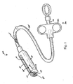
- Figure 1 shows a perspective view of a medical device 100 having a first elongate arm 110 and a second elongate arm 120 both of which are disposed within a slotted housing 130 having an opening 131 sized to substantially enclose the arms 110 and 120.
- the first elongate arm 110 and the second elongate arm 120 are shown substantially parallel to each other in the fully open position, which is shown more clearly in Figure 2a .
- the device 100 is designed to allow rotation of the arms 110 and 120 and their corresponding jaw members 160 and 170 from about 0° to about 180°,, thereby enabling a separation angle between the jaw members 160 and 170 to range from 0° to about 360°.
- the first elongate arm 110 in the fully open position is disposed along the bottom portion of opening 131 of the slotted housing 130.
- the first elongate arm 110 includes a first gear end 111 that is pivotally connected by a first pivot pin 118 along the distal end of the slotted housing 130.
- the first gear end 111 remains stationary as it intermeshes with a drive gear 150, which is disposed between the first gear end 111 and the second gear end 112, as seen more clearly in Figure 2A .
- the first elongate arm 110 further includes a first jaw member 160, which is shown disposed within the housing 130 along the proximal end thereof ( Figure 2a ).
- the jaw member 160 is shown positioned along an end opposite to the first gear end 111.
- the second elongate arm 120 in the fully open position is disposed along the top portion of opening 131 of the slotted housing 130, as can be seen in Figure 1 and Figure 2a .
- Figure 1 shows that the second elongate arm 120 includes a second gear end 112, which is pivotally connected by a second pivot pin 119 along the distal end of the slotted housing 130.
- the second gear end 112 remains stationary as it intermeshes with the drive gear 150.
- the second elongate arm 120 includes a second jaw member 170, which can be seen in Figure 1 to be disposed within the flexible housing 130 along the proximal end thereof.
- the second jaw member 170 is shown positioned along an end opposite to the second gear end 112.
- Figure 2A shows the first elongate arm 110 and the second elongate arm 120 in the fully open position.
- the fully open position is defined as the elongate arms 110 and 120 positioned substantially parallel to each other within a proximal end of the flexible slotted housing 130 such that the first and second jaw members 160 and 170 are spaced apart about 360° relative to each other.
- the fully closed position is defined as the elongate arms 110 and 120 positioned substantially parallel to each other and distally of the distal end of the housing 130 such that the first and second jaw members 160 and 170 are spaced at 0° relative to each other.
- the mechanism by which the elongate arms 110 and 120 rotate from the fully open position ( Figure 2A ) to the fully closed position ( Figure 2C ) enables a wider range of angular motion of arms 110 and 120 relative to conventional medical devices having rotatable members, such as, for example, grasping elements, cutting elements, or biopsy elements.
- the first elongate arm 110 and the second elongate arm 120 are configured to rotate independently of each other.
- the first elongate arm 110 is adapted to rotate 180° clockwise relative to a drive gear 150 ( Figure 2b ) and about pivot pin 118.
- the second elongate arm 120 is adapted to rotate 180 degrees counterclockwise relative to the drive gear 150 ( Figure 2b ) and about pivot pin 119.
- Figure 1 shows that the slotted housing 130 contains an opening 131 that is sufficiently sized to receive the first elongate arm 110 and the second elongate arm 120 therewithin.
- the distal end of the housing 130 has an opening 132 which allows the first and the second elongate arms 110 and 120 to pivot from the fully open position ( Figure 2a ) to the fully closed position ( Figure 2c ).
- the gear arrangement 300 includes a drive gear 150 intermeshed with the first gear end 111 and the second gear end 112.
- the drive gear 150 includes an elongated rack 151 having a first gear surface 188 and a second gear surface 189.
- a predetermined distal portion of the elongated rack 151 includes multiple first ribs 152 which laterally extend or protrude away from the first surface 188.
- a predetermined distal portion of elongate rack 151 also includes multiple second ribs 153 which laterally extend or protrude away from a second surface 189 of the elongate rack 151.
- first ribs 152 creates multiple first slots 192a-f therebetween, which are sized to receive a corresponding first set of teeth 154a-e contained along the outer surface of the first gear end 111.
- 192a refers to the most proximal first slot
- 192f refers to the most distal first slot.
- the spacing between adjacent second ribs 153 creates multiple second slots 193a-f therebetween, which are sized to receive a corresponding second set of teeth 155a-e contained along the outer surface of the second gear end 112.
- second slots 193a-f are positioned on the other side of the elongate rack 151 along back surface 189 ( Figure 3 ) and therefore are not visible in the cross sectional views of Figures 2a-2c . Similar designation is used in which 193a refers to the most proximal second slot, and 193f refers to the most distal second slot. Multiple second slots 193a-f along the first surface 188 of elongate rack 151 are aligned with multiple first slots 192a-f along with second surface 189 of the elongate rack 151. Figure 3 shows that the first set of teeth 154a-e extend only along face 194 of the first gear end 111.
- the second set of teeth 155a-e extend only along face 195 of the second gear end 112. Faces 194 and 195 are oriented opposite and away from each other to enable drive gear 150 to sufficiently engage with both the first set of teeth 154 of first gear end 111 and the second set of teeth 155 of the second gear end 112.
- the teeth 154 and 155 may be longer than conventional teeth in gear arrangements to enhance mesh engagement of the teeth 154a-e and 155a-e within their respective slots 192a-f and 193a-f along the drive gear 150.
- the meshed engagement of teeth 154a-e and 155a-e within their respective slots 192a-f and 193a-f is designed to be possible even when the overall profile of the device 100 must be substantially reduced to about 20 Fr or smaller, as is generally required for endoscopic procedures.
- conventional gear arrangements at such small diameters may need to utilize a drive gear having relatively shallow vertical indentations or grooves that engage with shorter teeth along the gear ends of the elongate arms.
- Such a gear design may be problematic as slippage between the teeth and the vertical grooves of the drive gear may occur due to the need to reduce the overall profile of the device. Accordingly, the above described gear arrangement 300 may be significantly less prone to slippage as the overall profile of the device is required to be reduced.
- gear arrangement 300 may be modified such that the rack 151 may only include a single set of laterally extended slots shared by both sets of teeth 154a-e and 155a-e.
- a single set of ribs may extend along one of the surfaces 188 and 189 of rack 151. Lateral slots would be created between the ribs, and the slots may be sized to receive both sets of teeth 154a-e and 155a-e.
- Figure 2a shows that first elongate arm 110 and the second elongate arm 120 are in the fully open position within the flexible housing 130.
- the outermost spoke 154a of the first gear end 111 is shown engaged with corresponding proximal-most slot 192a.
- the outermost spoke 155a of second gear end 112 is shown engaged with corresponding proximal-most slot 193a of drive gear 150.
- spoke 154a with corresponding slot 192a and spoke 155a with corresponding slot 193a enables the first and the second jaw members 160 and 170 to be oriented at 360° relative to each other within the proximal end of the flexible housing 130 ( Figure 2a ).
- a control handle 190 as shown in Figure 1 may be used to actuate the drive gear 150.
- a distal end of a drive wire 175 connects to a proximal end 176 of drive gear 150 ( Figure 2a ).
- Drive wire 175 is actuated by control handle 190.
- a proximal end of the drive wire 175 connects to the control handle 190.
- control handle 190 may be a scissors-type handle, a pin vise, or any other conventional handle suitable for moving a drive wire 175 relative to a sheath 195.
- the member may be formed from any material (i.e. metals, alloys, plastics, ceramics) and includes any elongate structure capable of longitudinal force transmission over typical endoscope and/or laparoscopic distances, including single filament or multifilament wires, stylets, tubes, catheters, plastic rods or strands, and the like.
- the sheath 195 may be a tubular member.
- the sheath 195 has a lumen which houses a drive wire 175, the drive wire 175 connecting at its distal end to the drive gear 150 and at its proximal end to a control handle 190.
- the sheath 195 allows connection of the drive wire 175 from the proximal end of the drive gear 150 to the spool 192, which will be explained in greater detail below.
- the distal end of sheath 195 is affixed to the proximal end of housing 130, and the proximal end of sheath 195 is affixed to control handle 190.
- the sheath 195 may range in length from about 160 cm to about 220 cm.
- the sheath 195 is a flexible tubular member and may be formed from any semi-rigid polymer.
- the sheath 195 can be formed from polyurethane, polyethylene, tetrafluoroethylene, polytetrafluoroethylene, perfluoalkoxl, fluorinated ethylene propylene, or the like.
- Other structures that can house the drive wire 175 are contemplated.
- the sheath 195 may be a wound coiled spring.
- Control handle 190 includes a stem 191 and a spool 192.
- Stem 191 includes a lumen through which drive wire 175 is disposed therewithin.
- Spool 192 is slidably engaged with stem 191, and spool 192 is operably connected to the drive wire 175.
- Spool 192 is provided with a range of slidable motion along stem 191.
- movement of the spool 192 in a proximal direction relative to the stem 191 causes drive wire 175 to proximally move relative to the sheath 195.
- the movement causes a tensile force to be transmitted to the drive wire 175.
- the drive wire 175 subsequently exerts a pulling force on the proximal end 176 of the drive gear 150 to cause the drive gear 150 to linearly move in the proximal direction, as indicated by the arrow in Figure 2a .
- Linear movement of the drive gear 150 in the proximal direction causes first gear end 111 to rotate about pivot pin 118 in a clockwise direction, as shown by the arrow about first gear end 111, thereby causing first elongate member 110 to rotate in a clockwise direction.
- the linear movement of the drive gear 150 in the proximal direction also causes the second gear end 112 to rotate about pivot pin 119 in a counterclockwise direction, as shown by the arrow about second gear end 112, thereby causing second elongate member 120 to rotate in a counterclockwise direction.
- Figure 2b shows that the first gear end 111 has rotated clockwise a sufficient amount to disengage the outermost spoke 154a of the first set of teeth 154 from slot 192a such that first spoke 154b engages within corresponding first slot 192b.
- Second gear end 112 has rotated counterclockwise a sufficient amount to disengage the outermost second spoke 155a from slot 193a such that second spoke 155b engages within corresponding slot 193b.
- Figure 2b shows that during the engagement, the teeth 154 and 155 of the first and second gear ends 111 and 112 are projected substantially vertically with the corresponding lateral slots 192 and 193 of the rack 151.
- first elongate arm 110 has rotated from the bottom of housing 130 approximately 45 degrees in a clockwise direction
- second elongate arm 120 has rotated from the top of housing 130 approximately 45 degrees in a counterclockwise direction, as shown in Figure 2b .
- Figure 2b shows that the drive gear 150 continues to be pulled in a proximal direction which will cause the first gear end 111 to further rotate in a clockwise direction such that first spoke 154b is disengaged from corresponding first slot 192b and thereafter first spoke 154c of first gear end 111 engages within corresponding slot 192c of drive gear 150.
- Such movement causes the first elongate arm to move an additional 45 degrees in the clockwise direction, thereby creating about 90° total movement from the fully closed position of Figure 2a .
- pulling drive gear 150 in the proximal direction causes the second gear end 112 to further rotate in a counterclockwise direction such that the second spoke 155b is disengaged from corresponding second slot 193b and thereafter second spoke 155c of second gear end 112 engages within corresponding slot 193c of the drive gear 150.
- This movement causes the second elongate arm 120 to move an additional 45° in the counterclockwise direction, thereby creating about 90° total movement from the fully open position of Figure 2a .
- the handle 190 may be pulled in the proximal direction until the first and the second elongate arms 110 and 120 have rotated 180° such that jaw members 160 and 170 are fully closed, as shown in Figure 2c .
- the tip of jaw member 160 is in contact with the tip of jaw member 170.
- Figure 2c shows that the first elongate arm 110 has been rotated 180 degrees in the clockwise direction from the open position of Figure 2a .
- the second elongate arm 120 has been rotated 180° in the counterclockwise direction from the open position of Figure 2a .
- the gear arrangement 300 in the fully closed position shows that the first spoke 154e is engaged within corresponding first slot 192e, and the second spoke 155e is engaged within corresponding second slot 193e.
- Such a wider range of movement of the jaw members 160 and 170 may enable the jaw members 160 and 170 to access and capture target tissue that may not typically be possible with conventional jaw members, which can only undergo a limited range of motion. Additionally, the ability for elongate arms 110 and 120 to be extended in the fully open position Figure 2c and be separated 360° from each other may enable a larger amount of tissue to be captured compared to conventional medical jaw devices.
- the first set of teeth and the second set of teeth were not required to extend completely around their respective gear ends 111 and 112, as each meshed engagement and subsequent disengagement of a single spoke with a corresponding slot created 45 degrees of rotational movement.
- five teeth were required to create about 180° movement of the first and the second elongate members 110 and 120.
- More than 5 teeth may be used in the gear arrangement 300 to decrease the incremental rotation created from meshed engagement-disengagement of a spoke and corresponding slot.
- less than 5 teeth may be used to increase the incremental rotation.
- the exact number of teeth around each of the gears may depend, in part, on the type of procedure into which device 100 is being utilized and the size constrains associated with such a procedure.
- a sufficient number of teeth and corresponding slots are provided so as to allow about 180° movement of the first and the second elongate arms 110 and 120.
- the above described mechanism for opening and closing jaw members 160 and 170 can be used for any type of jaw member, including but not limited to graspers, biopsy cups, scrapers, and scissors.
- the jaw mechanism and design as described above may be used for clips having detachable distal ends which may remain in a patient and mechanically maintain compression on a target structure after the particular procedure is completed.
- Inner surfaces of the jaw members 160 and 170 may include serrated features for enhancing the ability to severe tissue. The exact structure of the jaws members 160 and 170 may be dependent upon a variety of factors, including the particular application for the device 100.
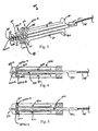
- FIG. 4 shows an example of an alternative gear arrangement 400.
- the central drive gear 410 includes a first set of grooves 412 a-e which engage with corresponding teeth 454a-e of a first gear 440.
- the drive gear 410 also includes a second set of grooves 411a-e which engage with corresponding teeth 455a-e of a second gear 450.
- the grooves 411 a-e are created along a top surface of an elongate member 490 of the drive gear 410, and the grooves 412a-e are created along a bottom surface of elongate member 490.
- each of five teeth 454a-e engage and subsequently disengage with corresponding grooves 412a-e
- each of five teeth 455a-e engage and subsequently disengage with corresponding grooves 411a-e.
- first elongate member 421 to rotate clockwise from the bottom opening of housing 130 and second elongate member 420 to rotate counterclockwise from the top opening of housing 130.
- Each of the elongate members 410 and 420 are capable of rotating 180 degrees from their open position as shown in Figure 4 .
- Figure 5 shows that a stopper element 510 may be disposed along the distal end of the drive gear 410 to prevent the drive gear 410 from proximally moving beyond the first gear end 111 and the second gear end 112 so as to disengage therefrom.
- the stopper element 510 is shown to have a length greater than the spacing between adjacent teeth 454a-e of first elongate arm 410 and adjacent teeth 455a-e of second elongate arm 420, thereby preventing stopper element 510 from engaging into the openings defined by the spacing of adjacent teeth 454a-e and 455a-e.
- the stopper element 510 is placed distally of the most distal slot or groove of the drive gear 150 along the distal portion of the elongate member 490.
- the flexible slotted housing 130 preferably has a longitudinal length sufficient to house and substantially the first and the second elongate arms 110 and 120 in their fully open position as shown in Figures 1 , 2 , 4, and 5 .
- the housing 130 preferably has a top and bottom opening 131 which is sized to receive elongate members 110 and 120.
- the distal end of the housing 130 also contains an opening 132 to enable a complete range of rotation of the members 110 and 120.
- the housing 130 is preferably made from any flexible polymeric material known in the art. As a result, the flexibility of the housing 130 may allow the device 100 to be navigated through an accessory channel of an endoscope and tortuous body lumens.
- the embodiments described herein may not be limited by a maximum length of elongate members 110 and 120, as may be likely with conventional medical devices having jaws.
- Such conventional medical devices tend to have elongate members which are too rigid to traverse tortuous bends as well an accessory channel of an endoscope. Accordingly, the length of such conventional elongate members often needs to be shortened to facilitate advancement through tortuous bends.
- the present embodiments as described herein may enable longer elongate members 110 and 120 to be introduced into the accessory channel of the endoscope and subsequent tortuous body lumens.
- the longitudinal length of elongate members 110 and 120 as contemplated herein may be about 0.5 inches (12.7 millimeters) or greater.
- One exemplary method of using the device 100 involves an endoscopic procedure not forming part of the invention.
- An endoscope is advanced through an esophagus and into the gastrointestinal tract of a patient.
- the device 100 is introduced into an accessory channel of an endoscope in which the elongate members 110 and 120 are in their fully open position as shown in Figure 1 , the jaw members 160 and 170 being spaced apart about 360°.
- the orientation of Figure 1 creates an overall reduced lateral profile of device 100 during advancement through accessory channel of the endoscope.
- the proximal end of the handle assembly 190 is advanced beyond a distal end of the accessory channel towards a target tissue site T ( FIG.
- the elongate members 110 and 120 are rotated about 180° in the configuration of Figure 2c such that corresponding jaw members 110 and 120 may close around the tissue to grasp the target tissue.
- the optional stopper element 510 ( Figure 5 ) may be utilized to prevent the drive gear 150 from being proximally pulled back beyond the first and second gear ends 111 and 112, thereby preventing disengagement of drive gear 150 from the gear ends 111 and 112.
- the drive gear 150 is pushed in the distal direction as shown by the arrow in Figure 2c . Movement of drive gear 150 in the distal direction causes meshed engagement of the drive gear 150 with the first gear end 111 so as to rotate the first gear end 111 and the first elongate arm 110 in the counterclockwise direction, as shown by the arrow about arm 110 in Figure 2c .
- the drive gear 150 is also in meshed engagement with the second gear end 112 so as to rotate second gear end 112 and second elongate arm 111 in the clockwise direction, as shown by the arrow about arm 120 in Figure 2c .
- the drive gear 150 may continue to be pushed in the distal direction until first elongate arm 110 and second elongate arm 120 are rotated back into the fully open position, as shown in Figure 2a .
- an additional proximal stopper element similar to distal stopper element 510 may be disposed proximal of the most proximal slot or groove of the drive gear 150 ( Figure 5 ) along the distal portion of the elongate rack 151.
- the proximal stopper element would have a length greater than the spacing between adjacent teeth 454a-e of first elongate arm 421 and adjacent teeth 455a-e of second elongate arm 420 ( Figure 5 ) to prevent the proximal stopper element 510 from engaging into the openings defined by spacing of adjacent teeth 454a-e and 455a-e.
- the above described method of use involves delivering the device 100 with the elongate members 110 and 120 positioned in a fully open configuration ( Figure 2a ) and completely disposed within the housing 130 during delivery.
- the sharp jaws 160 and 170 in their fully open configuration during delivery remain protected by being encapsulated within housing 130. Because conventional devices allow the jaw member to remain exposed, there may be a greater risk of the exposed jaw inadvertently contacting tissue that causes trauma to the patient during a procedure. Such risk is significantly eliminated with the above described device 100.
- the systems, devices and methods described above generally include operating on tissue through an internal bodily lumen
- the systems, devices and methods may be used on any object (e.g. to retrieve small pieces from hard to reach places, such as a lost ring in a drain or other household plumbing) or on any layer of material (e.g. fabrics, cloth, polymers, elastomers, plastics and rubber) that may or may not be associated with a human or animal body and a bodily lumen.
- the systems, devices and methods can find use in laboratory and industrial settings for manipulating one or more layers of material that may or may not find application to the human or animal body.
Description
- Medical devices for engaging tissue are used during several types of procedures, including open surgery, laparoscopic surgery, endoscopic surgery, or transluminal surgery. Such devices include graspers, snares, baskets and the like. One common type of tissue engagement medical device that is available for endoluminal engagement of body tissue is forceps. Conventional forceps includes a pair of hinged jaws located at a distal end of a tubular housing. The hinged jaws are commonly activated using a typical actuator such as a push/pull wire mechanism, in which an actuating element such as a wire extends through the tubular housing to connect to the jaws via a mechanical linkage, which in turn drives the jaws between a closed position and a "V" shaped open position. Closing the jaws from the "V" shaped open position causes the jaws to catch on, pinch, or entrap tissue during a procedure. The extent to which the jaws open is typically limited by the mechanical linkage to the "V" shape; usually the jaws are separated by about 90° in their open position.
US-5209747 describes a medical device having the features of the preamble of claim 1. - The invention is disclosed in claims 1 and 12 with preferred embodiments disclosed in the dependent claims.
- In a first aspect, a medical device is provided that improves the effectiveness of the jaws in procedures where a wider angular opening of the jaws is necessary for access and grasping of target tissue. The device comprises a drive gear, a first elongate arm, and a second elongate arm. The first elongate arm comprises a first jaw member and a first gear end. The first gear end is intermeshed with the drive gear. The second elongate arm comprises a second jaw member and a second gear end. The second gear end is intermeshed with the drive gear. The first elongate arm and the second elongate arm are each pivotable about the first gear end and the second gear end, respectively. Each of the first elongate arm and the second elongate arm is pivotable between a first closed position and a second open position. The first jaw member and the second jaw are disposed adjacent each other in the first closed position, while the first jaw member and the second jaw member are spaced apart by an angle of about 360° in the second position.
- In a second aspect, a medical device is provided. The medical device comprises a drive gear comprising an elongated rack having a longitudinal length. The drive gear further comprises a first gear surface and a second gear surface being opposed to the first gear surface. A plurality of first ribs laterally protrude away from the first gear surface of the elongate rack along the longitudinal length of the drive gear. The plurality of first ribs define a first plurality of slots therebetween, A plurality of second ribs laterally protrude away from the second gear surface of the elongate rack along the longitudinal length of the drive gear. The plurality of second ribs define a second plurality of slots therebetween. The device also includes a first elongate arm and a second elongate arm. The first elongate arm comprises a first jaw member and a first gear end, the first gear end comprising a first plurality of teeth pivotally connected within the distal end of the housing at a first pivot point, wherein the first plurality of teeth are engaged with the plurality of the first slots of the drive gear. The second elongate member comprises a second jaw member and a second gear end, the second gear end comprising a second plurality of teeth pivotally connected within the distal end of the housing at a second pivot point, the second plurality of teeth engaged with the plurality of the second slots of the drive gear. A housing is also provided. The housing comprises a proximal end, a distal end, and at least one opening extending between the proximal end and the distal end, wherein the housing receives the first and the second elongate arms in a fully open configuration to substantially enclose the arms.
- In a third aspect, a method for grasping an object is provided comprising the following steps. A medical device is provided. The device comprises a first elongate arm disposed within a housing and comprises a first jaw member and a first gear end. The first gear end is intermeshed with a drive gear at the distal end of the housing. A second elongate arm is disposed within the housing and comprises a second jaw member and a second gear end intermeshed with the drive gear at the distal end of the housing. The first elongate arm and the second elongate arm are independently pivotable with respect to each other about the first and the second gear ends respectively. Rotation of the first and the second elongate arms controls a spacing between the first jaw member and the second jaw member from about 0° to about 360°. The medical device is advanced to the object, e.g. through a bodily lumen to a target tissue site, this does not form part of the invention, with the first jaw member and the second jaw member in a fully open configuration being substantially enclosed within the housing, preferably in a substantially parallel arrangement at about 360° relative to each other. The drive gear is pulled in a proximal direction so as to cause engagement of the drive gear with the first gear end and the second gear end, thereby causing rotation of the first elongate arm in a clockwise direction about the first gear end from a bottom opening of the housing, and rotation of the second elongate arm in a counterclockwise direction about the second gear end from a top opening of the housing. The movement of the arms closes the first and the second jaw members around the object to grasp and retain the object.
- The invention may be more fully understood by reading the following description in conjunction with the drawings, in which:
-
Figure 1 shows a perspective view of a medical device with pivotable jaws having elongate members disposed within a flexible housing, the elongate members being in a closed position; -
Figure 2A shows a partial cross-sectional view of a distal end of the device ofFigure 1 ; -
Figure 2B shows the medical device with the first elongate member rotated 45° in a clockwise direction from a bottom opening of the housing and the second elongate member rotated 45° in a counterclockwise direction from a top opening of the housing; -
Figure 2C shows the medical device ofFigure 1 in which the elongate members have rotated to their fully closed position with the corresponding jaw members of elongate members disposed adjacent to each other; -
Figure 3 shows a gear arrangement that may be utilized in the medical device ofFigure 1 ; -
Figure 4 shows another gear arrangement that may be utilized in the device ofFigure 1 ; and -
Figure 5 shows yet another gear arrangement in which the drive gear comprises a stopper element placed distally of the distal-most groove of the drive gear, the stopper element preventing disengagement of the drive gear from both gear ends of the elongate members during proximal pulling of the drive gear. - The terms "proximal" and "distal" as used herein are intended to have a reference point relative to the user. Specifically, throughout the specification, the terms "distal" and "distally" shall denote a position, direction, or orientation that is generally away from the user, and the terms "proximal" and "proximally" shall denote a position, direction, or orientation that is generally towards the user.
- An exemplary medical device with pivotable jaws is shown in
Figure 1. Figure 1 shows a perspective view of amedical device 100 having a firstelongate arm 110 and a secondelongate arm 120 both of which are disposed within a slottedhousing 130 having an opening 131 sized to substantially enclose thearms elongate arm 110 and the secondelongate arm 120 are shown substantially parallel to each other in the fully open position, which is shown more clearly inFigure 2a . As will be explained in greater detail, thedevice 100 is designed to allow rotation of thearms corresponding jaw members jaw members minus 15°. For example, in the fully open position of thearms jaws housing 130. - The first
elongate arm 110 in the fully open position is disposed along the bottom portion of opening 131 of theslotted housing 130. The firstelongate arm 110 includes a first gear end 111 that is pivotally connected by afirst pivot pin 118 along the distal end of theslotted housing 130. The first gear end 111 remains stationary as it intermeshes with adrive gear 150, which is disposed between the first gear end 111 and thesecond gear end 112, as seen more clearly inFigure 2A . The firstelongate arm 110 further includes afirst jaw member 160, which is shown disposed within thehousing 130 along the proximal end thereof (Figure 2a ). Thejaw member 160 is shown positioned along an end opposite to the first gear end 111. - The second
elongate arm 120 in the fully open position is disposed along the top portion of opening 131 of theslotted housing 130, as can be seen inFigure 1 andFigure 2a .Figure 1 shows that the secondelongate arm 120 includes asecond gear end 112, which is pivotally connected by asecond pivot pin 119 along the distal end of the slottedhousing 130. Thesecond gear end 112 remains stationary as it intermeshes with thedrive gear 150. The secondelongate arm 120 includes asecond jaw member 170, which can be seen inFigure 1 to be disposed within theflexible housing 130 along the proximal end thereof. Thesecond jaw member 170 is shown positioned along an end opposite to thesecond gear end 112. -
Figure 2A shows the firstelongate arm 110 and the secondelongate arm 120 in the fully open position. The fully open position is defined as theelongate arms housing 130 such that the first andsecond jaw members Figure 2c , is defined as theelongate arms housing 130 such that the first andsecond jaw members elongate arms Figure 2A ) to the fully closed position (Figure 2C ) enables a wider range of angular motion ofarms elongate arm 110 and the secondelongate arm 120 are configured to rotate independently of each other. The firstelongate arm 110 is adapted to rotate 180° clockwise relative to a drive gear 150 (Figure 2b ) and aboutpivot pin 118. The secondelongate arm 120 is adapted to rotate 180 degrees counterclockwise relative to the drive gear 150 (Figure 2b ) and aboutpivot pin 119. 360° separation relative to each of thearms corresponding jaw members Figure 2c ). The rotation of thearms jaws -
Figure 1 shows that the slottedhousing 130 contains anopening 131 that is sufficiently sized to receive the firstelongate arm 110 and the secondelongate arm 120 therewithin. The distal end of thehousing 130 has anopening 132 which allows the first and the secondelongate arms Figure 2a ) to the fully closed position (Figure 2c ). - A detailed view of the gear arrangement 300 used in
Figure 1 andFigures 2a-2c is shown inFigure 3 . The gear arrangement 300 includes adrive gear 150 intermeshed with the first gear end 111 and thesecond gear end 112. Thedrive gear 150 includes anelongated rack 151 having a first gear surface 188 and asecond gear surface 189. A predetermined distal portion of theelongated rack 151 includes multiple first ribs 152 which laterally extend or protrude away from the first surface 188. A predetermined distal portion ofelongate rack 151 also includes multiplesecond ribs 153 which laterally extend or protrude away from asecond surface 189 of theelongate rack 151. The spacing between adjacent first ribs 152 creates multiplefirst slots 192a-f therebetween, which are sized to receive a corresponding first set ofteeth 154a-e contained along the outer surface of the first gear end 111. 192a refers to the most proximal first slot, and 192f refers to the most distal first slot. The spacing between adjacentsecond ribs 153 creates multiplesecond slots 193a-f therebetween, which are sized to receive a corresponding second set ofteeth 155a-e contained along the outer surface of thesecond gear end 112. Note that thesecond slots 193a-f are positioned on the other side of theelongate rack 151 along back surface 189 (Figure 3 ) and therefore are not visible in the cross sectional views ofFigures 2a-2c . Similar designation is used in which 193a refers to the most proximal second slot, and 193f refers to the most distal second slot. Multiplesecond slots 193a-f along the first surface 188 ofelongate rack 151 are aligned with multiplefirst slots 192a-f along withsecond surface 189 of theelongate rack 151.Figure 3 shows that the first set ofteeth 154a-e extend only along face 194 of the first gear end 111. The second set ofteeth 155a-e extend only along face 195 of thesecond gear end 112. Faces 194 and 195 are oriented opposite and away from each other to enabledrive gear 150 to sufficiently engage with both the first set ofteeth 154 of first gear end 111 and the second set of teeth 155 of thesecond gear end 112. In other words, theteeth 154 and 155 may be longer than conventional teeth in gear arrangements to enhance mesh engagement of theteeth 154a-e and 155a-e within theirrespective slots 192a-f and 193a-f along thedrive gear 150. The meshed engagement ofteeth 154a-e and 155a-e within theirrespective slots 192a-f and 193a-f is designed to be possible even when the overall profile of thedevice 100 must be substantially reduced to about 20 Fr or smaller, as is generally required for endoscopic procedures. On the contrary, conventional gear arrangements at such small diameters may need to utilize a drive gear having relatively shallow vertical indentations or grooves that engage with shorter teeth along the gear ends of the elongate arms. Such a gear design may be problematic as slippage between the teeth and the vertical grooves of the drive gear may occur due to the need to reduce the overall profile of the device. Accordingly, the above described gear arrangement 300 may be significantly less prone to slippage as the overall profile of the device is required to be reduced. - Variations to the above described gear arrangement 300 are contemplated. The gear arrangement 300 described above may be modified such that the
rack 151 may only include a single set of laterally extended slots shared by both sets ofteeth 154a-e and 155a-e. In particular, a single set of ribs may extend along one of thesurfaces 188 and 189 ofrack 151. Lateral slots would be created between the ribs, and the slots may be sized to receive both sets ofteeth 154a-e and 155a-e. - The mechanism by which the first
elongate arm 110 and the secondelongate arm 120 rotate will be explained in conjunction withFigures 2a-2c .Figure 2a shows that firstelongate arm 110 and the secondelongate arm 120 are in the fully open position within theflexible housing 130. In particular, theoutermost spoke 154a of the first gear end 111 is shown engaged with correspondingproximal-most slot 192a. The outermost spoke 155a ofsecond gear end 112 is shown engaged with correspondingproximal-most slot 193a ofdrive gear 150. The configuration ofspoke 154a withcorresponding slot 192a and spoke 155a withcorresponding slot 193a enables the first and thesecond jaw members Figure 2a ). - A control handle 190 as shown in
Figure 1 may be used to actuate thedrive gear 150. In particular, a distal end of adrive wire 175 connects to aproximal end 176 of drive gear 150 (Figure 2a ).Drive wire 175 is actuated bycontrol handle 190. A proximal end of thedrive wire 175 connects to thecontrol handle 190. It should be understood that other configurations of control handle 190 can be employed to actuatedrive wire 175. For example, the control handle 190 may be a scissors-type handle, a pin vise, or any other conventional handle suitable for moving adrive wire 175 relative to a sheath 195. Although the term "wire" is used to describe theelongate control member 175, the member may be formed from any material (i.e. metals, alloys, plastics, ceramics) and includes any elongate structure capable of longitudinal force transmission over typical endoscope and/or laparoscopic distances, including single filament or multifilament wires, stylets, tubes, catheters, plastic rods or strands, and the like. - The sheath 195 may be a tubular member. The sheath 195 has a lumen which houses a
drive wire 175, thedrive wire 175 connecting at its distal end to thedrive gear 150 and at its proximal end to acontrol handle 190. The sheath 195 allows connection of thedrive wire 175 from the proximal end of thedrive gear 150 to the spool 192, which will be explained in greater detail below. The distal end of sheath 195 is affixed to the proximal end ofhousing 130, and the proximal end of sheath 195 is affixed to controlhandle 190. The sheath 195 may range in length from about 160 cm to about 220 cm. The sheath 195 is a flexible tubular member and may be formed from any semi-rigid polymer. For example, the sheath 195 can be formed from polyurethane, polyethylene, tetrafluoroethylene, polytetrafluoroethylene, perfluoalkoxl, fluorinated ethylene propylene, or the like. Other structures that can house thedrive wire 175 are contemplated. For example, the sheath 195 may be a wound coiled spring.
Control handle 190 includes astem 191 and a spool 192.Stem 191 includes a lumen through which drivewire 175 is disposed therewithin. Spool 192 is slidably engaged withstem 191, and spool 192 is operably connected to thedrive wire 175. Spool 192 is provided with a range of slidable motion alongstem 191. Thus, movement of the spool 192 in a proximal direction relative to thestem 191 causes drivewire 175 to proximally move relative to the sheath 195. The movement causes a tensile force to be transmitted to thedrive wire 175. Thedrive wire 175 subsequently exerts a pulling force on theproximal end 176 of thedrive gear 150 to cause thedrive gear 150 to linearly move in the proximal direction, as indicated by the arrow inFigure 2a . Linear movement of thedrive gear 150 in the proximal direction causes first gear end 111 to rotate aboutpivot pin 118 in a clockwise direction, as shown by the arrow about first gear end 111, thereby causing firstelongate member 110 to rotate in a clockwise direction. The linear movement of thedrive gear 150 in the proximal direction also causes thesecond gear end 112 to rotate aboutpivot pin 119 in a counterclockwise direction, as shown by the arrow aboutsecond gear end 112, thereby causing secondelongate member 120 to rotate in a counterclockwise direction. -
Figure 2b shows that the first gear end 111 has rotated clockwise a sufficient amount to disengage theoutermost spoke 154a of the first set ofteeth 154 fromslot 192a such that first spoke 154b engages within corresponding first slot 192b.Second gear end 112 has rotated counterclockwise a sufficient amount to disengage the outermost second spoke 155a fromslot 193a such that second spoke 155b engages within corresponding slot 193b.Figure 2b shows that during the engagement, theteeth 154 and 155 of the first and second gear ends 111 and 112 are projected substantially vertically with the corresponding lateral slots 192 and 193 of therack 151. The net result is that the firstelongate arm 110 has rotated from the bottom ofhousing 130 approximately 45 degrees in a clockwise direction, and the secondelongate arm 120 has rotated from the top ofhousing 130 approximately 45 degrees in a counterclockwise direction, as shown inFigure 2b . -
Figure 2b shows that thedrive gear 150 continues to be pulled in a proximal direction which will cause the first gear end 111 to further rotate in a clockwise direction such that first spoke 154b is disengaged from corresponding first slot 192b and thereafter first spoke 154c of first gear end 111 engages within corresponding slot 192c ofdrive gear 150. Such movement causes the first elongate arm to move an additional 45 degrees in the clockwise direction, thereby creating about 90° total movement from the fully closed position ofFigure 2a . Similarly, pullingdrive gear 150 in the proximal direction causes thesecond gear end 112 to further rotate in a counterclockwise direction such that the second spoke 155b is disengaged from corresponding second slot 193b and thereafter second spoke 155c ofsecond gear end 112 engages within corresponding slot 193c of thedrive gear 150. This movement causes the secondelongate arm 120 to move an additional 45° in the counterclockwise direction, thereby creating about 90° total movement from the fully open position ofFigure 2a . - The
handle 190 may be pulled in the proximal direction until the first and the secondelongate arms jaw members Figure 2c . The tip ofjaw member 160 is in contact with the tip ofjaw member 170.Figure 2c shows that the firstelongate arm 110 has been rotated 180 degrees in the clockwise direction from the open position ofFigure 2a . The secondelongate arm 120 has been rotated 180° in the counterclockwise direction from the open position ofFigure 2a . The gear arrangement 300 in the fully closed position shows that the first spoke 154e is engaged within corresponding first slot 192e, and the second spoke 155e is engaged within corresponding second slot 193e. Such a wider range of movement of thejaw members jaw members elongate arms Figure 2c and be separated 360° from each other may enable a larger amount of tissue to be captured compared to conventional medical jaw devices. - In the above described embodiment of
Figures 2a-2c , the first set of teeth and the second set of teeth were not required to extend completely around their respective gear ends 111 and 112, as each meshed engagement and subsequent disengagement of a single spoke with a corresponding slot created 45 degrees of rotational movement. As a result, five teeth were required to create about 180° movement of the first and the secondelongate members device 100 is being utilized and the size constrains associated with such a procedure. Preferably, a sufficient number of teeth and corresponding slots are provided so as to allow about 180° movement of the first and the secondelongate arms - It should be understood that the above described mechanism for opening and closing
jaw members jaw members jaws members device 100. - Additional variations to the gear arrangement 300 (
Figure 3 ) described in conjunction withFigures 2a-2c are also contemplated.Figure 4 shows an example of analternative gear arrangement 400. Thecentral drive gear 410 includes a first set of grooves 412 a-e which engage withcorresponding teeth 454a-e of afirst gear 440. Thedrive gear 410 also includes a second set of grooves 411a-e which engage withcorresponding teeth 455a-e of asecond gear 450. Unlike therectangular slots 192a-f and 193a-f which are created along opposing sides of the elongate rack 151 (Figure 3 ), the grooves 411 a-e are created along a top surface of anelongate member 490 of thedrive gear 410, and the grooves 412a-e are created along a bottom surface ofelongate member 490. In the example ofFigure 4 , each of fiveteeth 454a-e engage and subsequently disengage with corresponding grooves 412a-e, and each of fiveteeth 455a-e engage and subsequently disengage with corresponding grooves 411a-e. Such meshed arrangement allows firstelongate member 421 to rotate clockwise from the bottom opening ofhousing 130 and secondelongate member 420 to rotate counterclockwise from the top opening ofhousing 130. Each of theelongate members Figure 4 . -
Figure 5 shows that astopper element 510 may be disposed along the distal end of thedrive gear 410 to prevent thedrive gear 410 from proximally moving beyond the first gear end 111 and thesecond gear end 112 so as to disengage therefrom. Thestopper element 510 is shown to have a length greater than the spacing betweenadjacent teeth 454a-e of firstelongate arm 410 andadjacent teeth 455a-e of secondelongate arm 420, thereby preventingstopper element 510 from engaging into the openings defined by the spacing ofadjacent teeth 454a-e and 455a-e. Accordingly, no further rotation of thefirst gear end 440 and thesecond gear end 450 may be possible when thestopper element 510 is abutted against the first and the second gear ends 440 and 450. Preferably, thestopper element 510 is placed distally of the most distal slot or groove of thedrive gear 150 along the distal portion of theelongate member 490. - The flexible slotted
housing 130 preferably has a longitudinal length sufficient to house and substantially the first and the secondelongate arms Figures 1 ,2 ,4, and 5 . Specifically, thehousing 130 preferably has a top andbottom opening 131 which is sized to receiveelongate members housing 130 also contains anopening 132 to enable a complete range of rotation of themembers housing 130 is preferably made from any flexible polymeric material known in the art. As a result, the flexibility of thehousing 130 may allow thedevice 100 to be navigated through an accessory channel of an endoscope and tortuous body lumens. Additionally, because theelongate members corresponding jaw members housing 130 during advancement to a target tissue site, the embodiments described herein may not be limited by a maximum length ofelongate members elongate members elongate members - One exemplary method of using the
device 100 involves an endoscopic procedure not forming part of the invention. An endoscope is advanced through an esophagus and into the gastrointestinal tract of a patient. Thedevice 100 is introduced into an accessory channel of an endoscope in which theelongate members Figure 1 , thejaw members Figure 1 creates an overall reduced lateral profile ofdevice 100 during advancement through accessory channel of the endoscope. The proximal end of thehandle assembly 190 is advanced beyond a distal end of the accessory channel towards a target tissue site T (FIG. 2C ) so as to advancedevice 100 through a bodily lumen to the target tissue site while the first and the secondelongate members Figure 1 ). Having reached the target tissue site, the firstelongate arm 110 withjaw member 160 is rotated from thebottom opening 131 ofhousing 130 in a clockwise direction and the secondelongate arm 120 withjaw member 170 is rotated from the top opening ofhousing 130 in a counterclockwise direction. Such rotational movement is shown inFigure 2b . The rotational movement is preferably achieved utilizing the gear arrangement 300 discussed above in conjunction withFigure 3 . Depending on the sizes of the body lumen and the location of target tissue, thearms Figure 2c . In this particular example, theelongate members Figure 2c such thatcorresponding jaw members Figure 5 ) may be utilized to prevent thedrive gear 150 from being proximally pulled back beyond the first and second gear ends 111 and 112, thereby preventing disengagement ofdrive gear 150 from the gear ends 111 and 112. - Having grasped the target tissue, the
drive gear 150 is pushed in the distal direction as shown by the arrow inFigure 2c . Movement ofdrive gear 150 in the distal direction causes meshed engagement of thedrive gear 150 with the first gear end 111 so as to rotate the first gear end 111 and the firstelongate arm 110 in the counterclockwise direction, as shown by the arrow aboutarm 110 inFigure 2c . Thedrive gear 150 is also in meshed engagement with thesecond gear end 112 so as to rotatesecond gear end 112 and second elongate arm 111 in the clockwise direction, as shown by the arrow aboutarm 120 inFigure 2c . Thedrive gear 150 may continue to be pushed in the distal direction until firstelongate arm 110 and secondelongate arm 120 are rotated back into the fully open position, as shown inFigure 2a . - Although not shown, an additional proximal stopper element similar to distal stopper element 510 (
Figure 5 ) may be disposed proximal of the most proximal slot or groove of the drive gear 150 (Figure 5 ) along the distal portion of theelongate rack 151. The proximal stopper element would have a length greater than the spacing betweenadjacent teeth 454a-e of firstelongate arm 421 andadjacent teeth 455a-e of second elongate arm 420 (Figure 5 ) to prevent theproximal stopper element 510 from engaging into the openings defined by spacing ofadjacent teeth 454a-e and 455a-e. Accordingly, no further rotation of the first gear end 111 and thesecond gear end 112 may be possible when the proximal stopper element is abutted against the first and the second gear ends 111 and 112. Having a pair of stopper elements in such a configuration alongelongate rack 151 ofdrive gear 150 reduces the risk of disengagement of thedrive gear 150 from the first and second gear ends 111 and 112 during either proximal pulling of drive gear 150 (i.e., to open thearms arms - As can be seen, unlike conventional grasping medical devices, the above described method of use involves delivering the
device 100 with theelongate members Figure 2a ) and completely disposed within thehousing 130 during delivery. Thesharp jaws housing 130. Because conventional devices allow the jaw member to remain exposed, there may be a greater risk of the exposed jaw inadvertently contacting tissue that causes trauma to the patient during a procedure. Such risk is significantly eliminated with the above describeddevice 100. - It will be recognized by those skilled in the art that, while the devices and methods described above generally include operating on tissue through an internal bodily lumen, it will be recognized that the systems, devices and methods may be used on any object (e.g. to retrieve small pieces from hard to reach places, such as a lost ring in a drain or other household plumbing) or on any layer of material (e.g. fabrics, cloth, polymers, elastomers, plastics and rubber) that may or may not be associated with a human or animal body and a bodily lumen. For example, the systems, devices and methods can find use in laboratory and industrial settings for manipulating one or more layers of material that may or may not find application to the human or animal body.
- While preferred embodiments of the invention have been described, it should be understood that the invention is not so limited, and modifications may be made without departing from the invention. The scope of the invention is defined by the appended claims, and all devices that come within the meaning of the claims, either literally or by equivalence, are intended to be embraced therein. Furthermore, the advantages described above are not necessarily the only advantages of the invention, and it is not necessarily expected that all of the described advantages will be achieved with every embodiment of the invention.
Claims (15)
- A medical device (100) comprising:a housing (130) having a proximal end and distal end, the housing (130) defining a longitudinal axis extending between the proximal and distal ends;a drive gear (150, 410) longitudinally slidable relative to the housing (130);an elongate control member (190, 490) having a distal end connected to the drive gear (150, 410) for sliding the drive gear (150, 410) longitudinally;a first elongate arm (110, 421) comprising a first jaw member (160) and a first gear end (111, 440), the first gear end (111, 440) intermeshed with the drive gear (150, 410) and pivotally attached to the housing (130); anda second elongate arm (120, 420) comprising a second jaw member (170) and a second gear end (112, 450), the second gear end (112, 450) intermeshed with the drive gear (150, 410) and pivotally attached to the housing (130), the second elongate arm (120, 420) disposed opposite to the first elongate arm (110, 421);wherein the first elongate arm (110, 421) and the second elongate arm (120, 420) are -pivotable between a first closed position and a second open position, the first jaw member (160) and the second jaw member (170) being disposed adjacent each other in the first closed position,characterised in thatthe first jaw member (160) and the second jaw member (170) are spaced apart by an angle of about 360° in the second open position.
- The medical device (100) of claim 1, wherein the housing (130) has at least one opening (131) sized to receive the first elongate arm (110, 421) and the second elongate arm (120, 420) in the second open position.
- The medical device (100) of claim 1, wherein the first elongate arm (110, 421), the second elongate arm (120, 420) and the drive gear (150, 410) are entirely contained within the housing (130) in the second open position.
- The medical device (100) of claim 1, wherein a distal end of the drive gear (150, 410) defines a stopper element (510) that does not mesh with the first (111, 440) and second (112, 450) gear ends.
- The medical device (100) of claim 1, wherein each of the first (110, 421) and the second (120, 420) elongate arms pivot through an arc of about 180° between the first closed position and the second open position.
- The medical device (100) of claim 5, the first gear end (111, 440) comprising a first curved gear surface (188) comprising a first plurality of teeth (154a-e, 454 a-e) that extend along the first curved gear surface (188) about 180°, and the second gear end (112, 450) comprising a second curved gear surface (189) comprising a second plurality of teeth (155a-e, 455 a-e) that extend along the second curved gear surface (189) about 180°.
- The medical device (100) of claim 6, wherein the drive gear (150, 410) includes a plurality of slots (192a-f, 193a-f, 411 a-e, 412a-e) separated by a plurality of ribs (152, 153) extending laterally relative to the longitudinal axis, and wherein the first (154a-e, 454 a-e) and the second (155a-e, 455 a-e) teeth project substantially perpendicular to the longitudinal axis when engaged within the lateral slots (192a-f, 193a-f, 411a-e, 412a-e).
- The medical device (100) of claim 1, wherein the drive gear (150, 410) comprises an elongated rack (151) defining the longitudinal axis and having a plurality of ribs (152, 153) extending laterally relative to the longitudinal axis.
- The medical device (100) of claim 2, wherein the at least one opening (131) of the housing (130) defines a first opening (131) extending longitudinally through the distal end of the housing (130) and opening laterally away from the longitudinal axis, and wherein the at least one opening (131) of the housing (130) further defines a second opening (131) extending longitudinally through the distal end of the housing (130) and opening laterally away from the longitudinal axis, the second opening (131) spaced opposite the first opening (131).
- The medical device (100) of claim 1, wherein the first elongate arm (110, 421) and the second elongate arm (120, 420) in the second open position are positioned proximal of the distal end of the housing (130).
- The medical device (100) of claim 1, wherein the first elongate arm (110, 421) and the second elongate arm (120, 420) have a longitudinal length of at least 12.7 millimeters and the overall diameter of the medical device (100) is less than or equal to 20 Fr.
- A non-surgical method for operating a medical device (100) comprising the steps of:a) providing a medical device (100) comprising:a first elongate arm (110, 421) disposed within a housing (130) and comprising a first jaw member (160) and a first gear end (111, 440), the first gear end (111, 440) intermeshed with a drive gear (150, 410) at the distal end of the housing (130);a second elongate arm (120, 420) disposed within the housing (130) and comprising a second jaw member (170) and a second gear end (112, 450) intermeshed with the drive gear (150, 410) at the distal end of the housing (130);wherein the first elongate arm (110, 421) and the second elongate arm (120, 420) are each pivotable about the first gear end (111, 440) and the second gear end (112, 450), respectively, and further wherein each of the first elongate arm (110, 421) and the second elongate arm (120, 420) is pivotable between a fully closed configuration and a fully open configuration;wherein the first jaw member (160) and the second jaw member (170) in the fully open configuration are substantially enclosed within the housing (130) in a substantially parallel arrangement with the first (160) and the second (170) jaw members disposed proximally of the first (111, 440) and the second (112, 450) gear ends;b) pulling the drive gear (150, 410) in a proximal direction so as to cause engagement of the drive gear (150, 410) with the first gear end (111, 440) and the second gear end (112, 450); and therebyc) rotating the first elongate arm (110, 421) in a clockwise direction about the first gear end (111, 440) from a bottom opening (131) of the housing (130) and rotating the second elongate arm (120, 420) in a counterclockwise direction about the second gear end (112, 450) from a top opening (131) of the housing (130) to bring them both into the fully closed configuration.
- The method of claim 12, wherein the first elongate arm (110, 421) and the second elongate arm (120, 420) are disposed distal of the distal end of the housing (130) in the fully closed configuration.
- The method of claim 13, further comprising the steps of:pushing the drive gear (150, 410) in a distal direction; androtating the first elongate arm (110, 421) in a counterclockwise direction and the second elongate arm (120, 420) in a clockwise direction so as to reconfigure the first jaw member (160) and the second jaw member (170) within the proximal end of the housing (130) in the fully open configuration.
- The method of claim 12, further comprising the step of pulling the drive gear (150, 410) in a proximal direction until a stopper element (510) prevents further rotational engagement of the drive gear (150, 410) with the first (111, 440) and the second (112, 450) gear ends.
Applications Claiming Priority (2)
| Application Number | Priority Date | Filing Date | Title |
|---|---|---|---|
| US14193408P | 2008-12-31 | 2008-12-31 | |
| PCT/US2009/069270 WO2010078163A1 (en) | 2008-12-31 | 2009-12-22 | Medical device with pivotable jaws |
Publications (2)
| Publication Number | Publication Date |
|---|---|
| EP2381860A1 EP2381860A1 (en) | 2011-11-02 |
| EP2381860B1 true EP2381860B1 (en) | 2015-03-25 |
Family
ID=42110326
Family Applications (1)
| Application Number | Title | Priority Date | Filing Date |
|---|---|---|---|
| EP09796258.3A Active EP2381860B1 (en) | 2008-12-31 | 2009-12-22 | Medical device with pivotable jaws |
Country Status (6)
| Country | Link |
|---|---|
| US (1) | US8317820B2 (en) |
| EP (1) | EP2381860B1 (en) |
| JP (1) | JP5602766B2 (en) |
| AU (1) | AU2009333028B2 (en) |
| CA (1) | CA2748516C (en) |
| WO (1) | WO2010078163A1 (en) |
Families Citing this family (20)
| Publication number | Priority date | Publication date | Assignee | Title |
|---|---|---|---|---|
| BR112012018338B8 (en) | 2009-12-22 | 2021-06-22 | Cook Medical Technologies Llc | medical devices with swivel and detachable claws |
| US10010336B2 (en) | 2009-12-22 | 2018-07-03 | Cook Medical Technologies, Inc. | Medical devices with detachable pivotable jaws |
| US8545519B2 (en) | 2009-12-22 | 2013-10-01 | Cook Medical Technologies Llc | Medical devices with detachable pivotable jaws |
| WO2012051188A2 (en) | 2010-10-11 | 2012-04-19 | Cook Medical Technologies Llc | Medical devices with detachable pivotable jaws |
| EP2627268B8 (en) | 2010-10-11 | 2017-07-26 | Cook Medical Technologies LLC | Medical devices with detachable pivotable jaws |
| WO2012051191A2 (en) | 2010-10-11 | 2012-04-19 | Cook Medical Technologies Llc | Medical devices with detachable pivotable jaws |
| BR112013015246B1 (en) | 2010-12-15 | 2020-11-24 | Cook Medical Technologies Llc | medical device for engaging tissue |
| US11083475B2 (en) | 2012-02-22 | 2021-08-10 | Carter J. Kovarik | Medical device to remove an obstruction from a body lumen, vessel or organ |
| US10226266B2 (en) | 2012-02-22 | 2019-03-12 | Carter J. Kovarik | Selectively bendable remote gripping tool |
| US9901245B2 (en) | 2012-02-22 | 2018-02-27 | Carter J. Kovarik | Selectively bendable remote gripping tool |
| US9592066B2 (en) | 2012-02-22 | 2017-03-14 | Carter J. Kovarik | Selectively bendable remote gripping tool |
| USD780547S1 (en) | 2013-08-08 | 2017-03-07 | Carter J. Kovarik | Pick up device with flexible shaft portion |
| US9832980B2 (en) | 2012-02-22 | 2017-12-05 | Carter J. Kovarik | Selectively bendable remote gripping tool |
| EP2810607B1 (en) * | 2012-03-21 | 2016-05-18 | Olympus Corporation | Endoscopic treatment instrument |
| US10285575B2 (en) * | 2012-07-02 | 2019-05-14 | Cook Medical Technologies Llc | Endoscopic access system having a detachable handle |
| US20140135820A1 (en) * | 2012-11-13 | 2014-05-15 | Alcon Research, Ltd. | Disposable capsulorhexis forceps |
| JP5989230B2 (en) * | 2013-03-28 | 2016-09-07 | オリンパス株式会社 | Medical instruments and medical systems |
| US9827141B2 (en) | 2013-06-21 | 2017-11-28 | Novartis Ag | Systems and techniques for tissue manipulation during ocular surgery |
| EP4059454A1 (en) * | 2013-12-11 | 2022-09-21 | Covidien LP | Surgical device for grasping and shearing |
| CN114159128B (en) * | 2021-11-12 | 2023-07-07 | 浙江大学 | Compact robot-assisted minimally invasive surgery clamp |
Family Cites Families (63)
| Publication number | Priority date | Publication date | Assignee | Title |
|---|---|---|---|---|
| US720385A (en) | 1902-10-01 | 1903-02-10 | Burlington Brass Works | Pipe-wrench. |
| US2614445A (en) * | 1949-11-25 | 1952-10-21 | James T Clark | Flywheel spanner wrench with tooth engaging abutment |
| US5029355A (en) * | 1990-06-27 | 1991-07-09 | Hai Thai | Folding utility tool |
| US5209747A (en) * | 1990-12-13 | 1993-05-11 | Knoepfler Dennis J | Adjustable angle medical forceps |
| US5411481A (en) * | 1992-04-08 | 1995-05-02 | American Cyanamid Co. | Surgical purse string suturing instrument and method |
| US5275615A (en) * | 1992-09-11 | 1994-01-04 | Anthony Rose | Medical instrument having gripping jaws |
| US5527321A (en) * | 1993-07-14 | 1996-06-18 | United States Surgical Corporation | Instrument for closing trocar puncture wounds |
| US5797923A (en) * | 1997-05-12 | 1998-08-25 | Aiyar; Harish | Electrode delivery instrument |
| US6835200B2 (en) * | 1999-06-22 | 2004-12-28 | Ndo Surgical. Inc. | Method and devices for tissue reconfiguration |
| US8574243B2 (en) * | 1999-06-25 | 2013-11-05 | Usgi Medical, Inc. | Apparatus and methods for forming and securing gastrointestinal tissue folds |
| US6358197B1 (en) * | 1999-08-13 | 2002-03-19 | Enteric Medical Technologies, Inc. | Apparatus for forming implants in gastrointestinal tract and kit for use therewith |
| US7232445B2 (en) * | 2000-12-06 | 2007-06-19 | Id, Llc | Apparatus for the endoluminal treatment of gastroesophageal reflux disease (GERD) |
| US8100824B2 (en) * | 2003-05-23 | 2012-01-24 | Intuitive Surgical Operations, Inc. | Tool with articulation lock |
| US7736372B2 (en) * | 2003-11-13 | 2010-06-15 | Usgi Medical, Inc. | Apparatus and methods for endoscopic suturing |
| US20050251189A1 (en) * | 2004-05-07 | 2005-11-10 | Usgi Medical Inc. | Multi-position tissue manipulation assembly |
| JP4643328B2 (en) * | 2004-04-07 | 2011-03-02 | オリンパス株式会社 | Medical ligature suturing device |
| US8512229B2 (en) * | 2004-04-14 | 2013-08-20 | Usgi Medical Inc. | Method and apparatus for obtaining endoluminal access |
| US20050272977A1 (en) * | 2004-04-14 | 2005-12-08 | Usgi Medical Inc. | Methods and apparatus for performing endoluminal procedures |
| US7736374B2 (en) * | 2004-05-07 | 2010-06-15 | Usgi Medical, Inc. | Tissue manipulation and securement system |
| US20090326578A1 (en) * | 2004-09-30 | 2009-12-31 | Usgi Medical, Inc. | Interlocking tissue anchor apparatus and methods |
| WO2006044428A2 (en) * | 2004-10-14 | 2006-04-27 | Inventio Llc | Endoscopic multiple biopsy forceps with swing member |
| WO2006096169A1 (en) * | 2005-03-03 | 2006-09-14 | Granit Medical Innovations, Llc | Needle biopsy forceps with integral sample ejector |
| US7766810B2 (en) * | 2005-03-10 | 2010-08-03 | Olympus Medical Systems Corp. | Probing method and holding method for luminal organ |
| US20060266161A1 (en) * | 2005-05-31 | 2006-11-30 | Mulcaire Susan A B | Modified wine bottle opener |
| US9962066B2 (en) * | 2005-12-30 | 2018-05-08 | Intuitive Surgical Operations, Inc. | Methods and apparatus to shape flexible entry guides for minimally invasive surgery |
| DE102006003548B4 (en) * | 2006-01-24 | 2007-11-15 | Olympus Winter & Ibe Gmbh | Pliers or scissors instrument with gearbox connection |
| US7815652B2 (en) * | 2006-03-21 | 2010-10-19 | Ethicon Endo-Surgery, Inc. | Surgical fastener and instrument |
| EP1862125B1 (en) * | 2006-05-31 | 2011-08-03 | Covidien AG | Medical suturing tool with gripping device |
| US9561045B2 (en) * | 2006-06-13 | 2017-02-07 | Intuitive Surgical Operations, Inc. | Tool with rotation lock |
| JP4961534B2 (en) * | 2006-06-30 | 2012-06-27 | 学校法人自治医科大学 | Medical holder and method of using medical holder |
| US8475453B2 (en) * | 2006-10-06 | 2013-07-02 | Covidien Lp | Endoscopic vessel sealer and divider having a flexible articulating shaft |
| DE102006052407A1 (en) * | 2006-11-08 | 2008-05-15 | Olympus Winter & Ibe Gmbh | Surgical jaw instrument, has actuating rod and jaw head connected detachably with handling device transverse to shaft direction or in proximal direction parallel to shaft direction, and cable rigidly connected to actuating rod |
| US8062306B2 (en) * | 2006-12-14 | 2011-11-22 | Ethicon Endo-Surgery, Inc. | Manually articulating devices |
| US20080171907A1 (en) * | 2007-01-12 | 2008-07-17 | Ethicon Endo-Surgery, Inc. | Magnetic Tissue Grasping |
| JP5297816B2 (en) * | 2007-01-26 | 2013-09-25 | オリンパスメディカルシステムズ株式会社 | Gripping device |
| US20080228202A1 (en) * | 2007-03-16 | 2008-09-18 | Ethicon Endo-Surgery, Inc. | Endoscopic tissue approximation system |
| US20080228199A1 (en) * | 2007-03-16 | 2008-09-18 | Ethicon Endo-Surgery, Inc. | Endoscopic tissue approximation method |
| US20080234703A1 (en) * | 2007-03-23 | 2008-09-25 | Ethicon Endo-Surgery, Inc. | Tissue approximation system |
| US8852216B2 (en) * | 2007-03-23 | 2014-10-07 | Ethicon Endo-Surgery, Inc. | Tissue approximation methods |
| US7722628B2 (en) * | 2007-04-04 | 2010-05-25 | Ethicon Endo-Surgery, Inc. | Device for plicating and fastening gastric tissue |
| US8092489B2 (en) * | 2007-04-17 | 2012-01-10 | Usgi Medical, Inc. | Tissue grasping apparatus |
| US8591399B2 (en) * | 2007-04-25 | 2013-11-26 | Karl Storz Endovision, Inc. | Surgical method utilizing transluminal endoscope and instruments |
| US8500629B2 (en) * | 2007-04-30 | 2013-08-06 | Ethicon Endo-Surgery, Inc. | Endoscopic device |
| US20080300624A1 (en) * | 2007-05-30 | 2008-12-04 | Ethicon Endo-Surgery, Inc. | Tissue Stabilizer and Fastener |
| US20080300461A1 (en) * | 2007-05-31 | 2008-12-04 | Ethicon Endo-Surgery, Inc. | Endoscopic Device |
| US8088062B2 (en) * | 2007-06-28 | 2012-01-03 | Ethicon Endo-Surgery, Inc. | Interchangeable endoscopic end effectors |
| US20100217151A1 (en) * | 2007-07-11 | 2010-08-26 | Zach Gostout | Methods and Systems for Performing Submucosal Medical Procedures |
| US8128592B2 (en) * | 2007-07-11 | 2012-03-06 | Apollo Endosurgery, Inc. | Methods and systems for performing submucosal medical procedures |
| US8568410B2 (en) * | 2007-08-31 | 2013-10-29 | Ethicon Endo-Surgery, Inc. | Electrical ablation surgical instruments |
| US8758342B2 (en) * | 2007-11-28 | 2014-06-24 | Covidien Ag | Cordless power-assisted medical cauterization and cutting device |
| US20090143794A1 (en) * | 2007-11-29 | 2009-06-04 | Conlon Sean P | Tissue resection device |
| US20090192344A1 (en) * | 2008-01-24 | 2009-07-30 | Ethicon Endo-Surgery, Inc. | Surgical devices for manipulating tissue |
| US20090326518A1 (en) * | 2008-02-14 | 2009-12-31 | Rabin Barry H | Devices and methods for manipulating tissue |
| US8792966B2 (en) * | 2008-03-03 | 2014-07-29 | Ethicon Endo-Surgery, Inc. | Transluminal tissue markers |
| US8070759B2 (en) * | 2008-05-30 | 2011-12-06 | Ethicon Endo-Surgery, Inc. | Surgical fastening device |
| US8906035B2 (en) * | 2008-06-04 | 2014-12-09 | Ethicon Endo-Surgery, Inc. | Endoscopic drop off bag |
| US8303581B2 (en) * | 2008-09-02 | 2012-11-06 | Covidien Lp | Catheter with remotely extendible instruments |
| US20100331622A2 (en) * | 2008-11-25 | 2010-12-30 | Ethicon Endo-Surgery, Inc. | Tissue manipulation devices |
| US9226772B2 (en) * | 2009-01-30 | 2016-01-05 | Ethicon Endo-Surgery, Inc. | Surgical device |
| US20100198248A1 (en) * | 2009-02-02 | 2010-08-05 | Ethicon Endo-Surgery, Inc. | Surgical dissector |
| US20100249498A1 (en) * | 2009-03-24 | 2010-09-30 | Tyco Healthcare Group Lp | Endoscopic Apparatus for Manipulating Tissue |
| US20100249700A1 (en) * | 2009-03-27 | 2010-09-30 | Ethicon Endo-Surgery, Inc. | Surgical instruments for in vivo assembly |
| CN202119325U (en) * | 2011-06-23 | 2012-01-18 | 沙洲工学院 | Folding type slingshot |
-
2009
- 2009-12-22 US US12/645,004 patent/US8317820B2/en active Active
- 2009-12-22 WO PCT/US2009/069270 patent/WO2010078163A1/en active Application Filing
- 2009-12-22 AU AU2009333028A patent/AU2009333028B2/en active Active
- 2009-12-22 EP EP09796258.3A patent/EP2381860B1/en active Active
- 2009-12-22 CA CA2748516A patent/CA2748516C/en active Active
- 2009-12-22 JP JP2011544506A patent/JP5602766B2/en active Active
Also Published As
| Publication number | Publication date |
|---|---|
| JP2012513871A (en) | 2012-06-21 |
| US8317820B2 (en) | 2012-11-27 |
| WO2010078163A1 (en) | 2010-07-08 |
| CA2748516C (en) | 2014-10-14 |
| AU2009333028B2 (en) | 2013-10-17 |
| US20100168787A1 (en) | 2010-07-01 |
| AU2009333028A1 (en) | 2011-07-21 |
| EP2381860A1 (en) | 2011-11-02 |
| JP5602766B2 (en) | 2014-10-08 |
| CA2748516A1 (en) | 2010-07-08 |
Similar Documents
| Publication | Publication Date | Title |
|---|---|---|
| EP2381860B1 (en) | Medical device with pivotable jaws | |
| JP5073333B2 (en) | Surgical fasteners and surgical instruments | |
| US9427256B2 (en) | Surgical instrument guide device | |
| CN101513338B (en) | Medical treatment endoscope | |
| US9308049B2 (en) | Medical treatment endoscope | |
| US8728118B2 (en) | Tool with end effector force limiter | |
| EP1836979B1 (en) | Medical instrument having an engagement mechanism | |
| EP2651316B1 (en) | Medical devices with detachable pivotable jaws | |
| US8179074B2 (en) | Rotation actuator for endoscopic devices | |
| US20170238952A1 (en) | Multi-functional medical device | |
| US20120150155A1 (en) | Instrument Control Device | |
| US20230404595A1 (en) | Large tissue defect recruiting device |
Legal Events
| Date | Code | Title | Description |
|---|---|---|---|
| PUAI | Public reference made under article 153(3) epc to a published international application that has entered the european phase |
Free format text: ORIGINAL CODE: 0009012 |
|
| 17P | Request for examination filed |
Effective date: 20110725 |
|
| AK | Designated contracting states |
Kind code of ref document: A1 Designated state(s): AT BE BG CH CY CZ DE DK EE ES FI FR GB GR HR HU IE IS IT LI LT LU LV MC MK MT NL NO PL PT RO SE SI SK SM TR |
|
| RAP1 | Party data changed (applicant data changed or rights of an application transferred) |
Owner name: COOK MEDICAL TECHNOLOGIES LLC |
|
| DAX | Request for extension of the european patent (deleted) | ||
| GRAP | Despatch of communication of intention to grant a patent |
Free format text: ORIGINAL CODE: EPIDOSNIGR1 |
|
| INTG | Intention to grant announced |
Effective date: 20141020 |
|
| RIN1 | Information on inventor provided before grant (corrected) |
Inventor name: SURTI, VIHAR C. |
|
| GRAS | Grant fee paid |
Free format text: ORIGINAL CODE: EPIDOSNIGR3 |
|
| GRAA | (expected) grant |
Free format text: ORIGINAL CODE: 0009210 |
|
| AK | Designated contracting states |
Kind code of ref document: B1 Designated state(s): AT BE BG CH CY CZ DE DK EE ES FI FR GB GR HR HU IE IS IT LI LT LU LV MC MK MT NL NO PL PT RO SE SI SK SM TR |
|
| REG | Reference to a national code |
Ref country code: GB Ref legal event code: FG4D |
|
| REG | Reference to a national code |
Ref country code: CH Ref legal event code: EP |
|
| REG | Reference to a national code |
Ref country code: IE Ref legal event code: FG4D |
|
| REG | Reference to a national code |
Ref country code: DE Ref legal event code: R096 Ref document number: 602009030236 Country of ref document: DE Effective date: 20150507 |
|
| REG | Reference to a national code |
Ref country code: AT Ref legal event code: REF Ref document number: 717372 Country of ref document: AT Kind code of ref document: T Effective date: 20150515 |
|
| PG25 | Lapsed in a contracting state [announced via postgrant information from national office to epo] |
Ref country code: HR Free format text: LAPSE BECAUSE OF FAILURE TO SUBMIT A TRANSLATION OF THE DESCRIPTION OR TO PAY THE FEE WITHIN THE PRESCRIBED TIME-LIMIT Effective date: 20150325 Ref country code: LT Free format text: LAPSE BECAUSE OF FAILURE TO SUBMIT A TRANSLATION OF THE DESCRIPTION OR TO PAY THE FEE WITHIN THE PRESCRIBED TIME-LIMIT Effective date: 20150325 Ref country code: SE Free format text: LAPSE BECAUSE OF FAILURE TO SUBMIT A TRANSLATION OF THE DESCRIPTION OR TO PAY THE FEE WITHIN THE PRESCRIBED TIME-LIMIT Effective date: 20150325 Ref country code: NO Free format text: LAPSE BECAUSE OF FAILURE TO SUBMIT A TRANSLATION OF THE DESCRIPTION OR TO PAY THE FEE WITHIN THE PRESCRIBED TIME-LIMIT Effective date: 20150625 Ref country code: FI Free format text: LAPSE BECAUSE OF FAILURE TO SUBMIT A TRANSLATION OF THE DESCRIPTION OR TO PAY THE FEE WITHIN THE PRESCRIBED TIME-LIMIT Effective date: 20150325 |
|
| REG | Reference to a national code |
Ref country code: AT Ref legal event code: MK05 Ref document number: 717372 Country of ref document: AT Kind code of ref document: T Effective date: 20150325 |
|
| REG | Reference to a national code |
Ref country code: LT Ref legal event code: MG4D |
|
| PG25 | Lapsed in a contracting state [announced via postgrant information from national office to epo] |
Ref country code: GR Free format text: LAPSE BECAUSE OF FAILURE TO SUBMIT A TRANSLATION OF THE DESCRIPTION OR TO PAY THE FEE WITHIN THE PRESCRIBED TIME-LIMIT Effective date: 20150626 Ref country code: LV Free format text: LAPSE BECAUSE OF FAILURE TO SUBMIT A TRANSLATION OF THE DESCRIPTION OR TO PAY THE FEE WITHIN THE PRESCRIBED TIME-LIMIT Effective date: 20150325 |
|
| PG25 | Lapsed in a contracting state [announced via postgrant information from national office to epo] |
Ref country code: NL Free format text: LAPSE BECAUSE OF FAILURE TO SUBMIT A TRANSLATION OF THE DESCRIPTION OR TO PAY THE FEE WITHIN THE PRESCRIBED TIME-LIMIT Effective date: 20150325 |
|
| PG25 | Lapsed in a contracting state [announced via postgrant information from national office to epo] |
Ref country code: RO Free format text: LAPSE BECAUSE OF FAILURE TO SUBMIT A TRANSLATION OF THE DESCRIPTION OR TO PAY THE FEE WITHIN THE PRESCRIBED TIME-LIMIT Effective date: 20150325 Ref country code: CZ Free format text: LAPSE BECAUSE OF FAILURE TO SUBMIT A TRANSLATION OF THE DESCRIPTION OR TO PAY THE FEE WITHIN THE PRESCRIBED TIME-LIMIT Effective date: 20150325 Ref country code: EE Free format text: LAPSE BECAUSE OF FAILURE TO SUBMIT A TRANSLATION OF THE DESCRIPTION OR TO PAY THE FEE WITHIN THE PRESCRIBED TIME-LIMIT Effective date: 20150325 Ref country code: ES Free format text: LAPSE BECAUSE OF FAILURE TO SUBMIT A TRANSLATION OF THE DESCRIPTION OR TO PAY THE FEE WITHIN THE PRESCRIBED TIME-LIMIT Effective date: 20150325 Ref country code: SK Free format text: LAPSE BECAUSE OF FAILURE TO SUBMIT A TRANSLATION OF THE DESCRIPTION OR TO PAY THE FEE WITHIN THE PRESCRIBED TIME-LIMIT Effective date: 20150325 Ref country code: PT Free format text: LAPSE BECAUSE OF FAILURE TO SUBMIT A TRANSLATION OF THE DESCRIPTION OR TO PAY THE FEE WITHIN THE PRESCRIBED TIME-LIMIT Effective date: 20150727 |
|
| PG25 | Lapsed in a contracting state [announced via postgrant information from national office to epo] |
Ref country code: IS Free format text: LAPSE BECAUSE OF FAILURE TO SUBMIT A TRANSLATION OF THE DESCRIPTION OR TO PAY THE FEE WITHIN THE PRESCRIBED TIME-LIMIT Effective date: 20150725 Ref country code: AT Free format text: LAPSE BECAUSE OF FAILURE TO SUBMIT A TRANSLATION OF THE DESCRIPTION OR TO PAY THE FEE WITHIN THE PRESCRIBED TIME-LIMIT Effective date: 20150325 Ref country code: PL Free format text: LAPSE BECAUSE OF FAILURE TO SUBMIT A TRANSLATION OF THE DESCRIPTION OR TO PAY THE FEE WITHIN THE PRESCRIBED TIME-LIMIT Effective date: 20150325 |
|
| REG | Reference to a national code |
Ref country code: DE Ref legal event code: R097 Ref document number: 602009030236 Country of ref document: DE |
|
| PG25 | Lapsed in a contracting state [announced via postgrant information from national office to epo] |
Ref country code: DK Free format text: LAPSE BECAUSE OF FAILURE TO SUBMIT A TRANSLATION OF THE DESCRIPTION OR TO PAY THE FEE WITHIN THE PRESCRIBED TIME-LIMIT Effective date: 20150325 |
|
| PLBE | No opposition filed within time limit |
Free format text: ORIGINAL CODE: 0009261 |
|
| STAA | Information on the status of an ep patent application or granted ep patent |
Free format text: STATUS: NO OPPOSITION FILED WITHIN TIME LIMIT |
|
| 26N | No opposition filed |
Effective date: 20160105 |
|
| PG25 | Lapsed in a contracting state [announced via postgrant information from national office to epo] |
Ref country code: IT Free format text: LAPSE BECAUSE OF FAILURE TO SUBMIT A TRANSLATION OF THE DESCRIPTION OR TO PAY THE FEE WITHIN THE PRESCRIBED TIME-LIMIT Effective date: 20150325 |
|
| PG25 | Lapsed in a contracting state [announced via postgrant information from national office to epo] |
Ref country code: SI Free format text: LAPSE BECAUSE OF FAILURE TO SUBMIT A TRANSLATION OF THE DESCRIPTION OR TO PAY THE FEE WITHIN THE PRESCRIBED TIME-LIMIT Effective date: 20150325 Ref country code: BE Free format text: LAPSE BECAUSE OF NON-PAYMENT OF DUE FEES Effective date: 20151231 |
|
| PG25 | Lapsed in a contracting state [announced via postgrant information from national office to epo] |
Ref country code: LU Free format text: LAPSE BECAUSE OF FAILURE TO SUBMIT A TRANSLATION OF THE DESCRIPTION OR TO PAY THE FEE WITHIN THE PRESCRIBED TIME-LIMIT Effective date: 20151222 Ref country code: MC Free format text: LAPSE BECAUSE OF FAILURE TO SUBMIT A TRANSLATION OF THE DESCRIPTION OR TO PAY THE FEE WITHIN THE PRESCRIBED TIME-LIMIT Effective date: 20150325 |
|
| REG | Reference to a national code |
Ref country code: CH Ref legal event code: PL |
|
| PG25 | Lapsed in a contracting state [announced via postgrant information from national office to epo] |
Ref country code: BE Free format text: LAPSE BECAUSE OF FAILURE TO SUBMIT A TRANSLATION OF THE DESCRIPTION OR TO PAY THE FEE WITHIN THE PRESCRIBED TIME-LIMIT Effective date: 20150325 |
|
| REG | Reference to a national code |
Ref country code: FR Ref legal event code: ST Effective date: 20160831 |
|
| PG25 | Lapsed in a contracting state [announced via postgrant information from national office to epo] |
Ref country code: LI Free format text: LAPSE BECAUSE OF NON-PAYMENT OF DUE FEES Effective date: 20151231 Ref country code: CH Free format text: LAPSE BECAUSE OF NON-PAYMENT OF DUE FEES Effective date: 20151231 |
|
| PG25 | Lapsed in a contracting state [announced via postgrant information from national office to epo] |
Ref country code: FR Free format text: LAPSE BECAUSE OF NON-PAYMENT OF DUE FEES Effective date: 20151231 |
|
| PG25 | Lapsed in a contracting state [announced via postgrant information from national office to epo] |
Ref country code: SM Free format text: LAPSE BECAUSE OF FAILURE TO SUBMIT A TRANSLATION OF THE DESCRIPTION OR TO PAY THE FEE WITHIN THE PRESCRIBED TIME-LIMIT Effective date: 20150325 Ref country code: HU Free format text: LAPSE BECAUSE OF FAILURE TO SUBMIT A TRANSLATION OF THE DESCRIPTION OR TO PAY THE FEE WITHIN THE PRESCRIBED TIME-LIMIT; INVALID AB INITIO Effective date: 20091222 Ref country code: BG Free format text: LAPSE BECAUSE OF FAILURE TO SUBMIT A TRANSLATION OF THE DESCRIPTION OR TO PAY THE FEE WITHIN THE PRESCRIBED TIME-LIMIT Effective date: 20150325 |
|
| PG25 | Lapsed in a contracting state [announced via postgrant information from national office to epo] |
Ref country code: CY Free format text: LAPSE BECAUSE OF FAILURE TO SUBMIT A TRANSLATION OF THE DESCRIPTION OR TO PAY THE FEE WITHIN THE PRESCRIBED TIME-LIMIT Effective date: 20150325 |
|
| PG25 | Lapsed in a contracting state [announced via postgrant information from national office to epo] |
Ref country code: MT Free format text: LAPSE BECAUSE OF FAILURE TO SUBMIT A TRANSLATION OF THE DESCRIPTION OR TO PAY THE FEE WITHIN THE PRESCRIBED TIME-LIMIT Effective date: 20150325 Ref country code: TR Free format text: LAPSE BECAUSE OF FAILURE TO SUBMIT A TRANSLATION OF THE DESCRIPTION OR TO PAY THE FEE WITHIN THE PRESCRIBED TIME-LIMIT Effective date: 20150325 |
|
| PG25 | Lapsed in a contracting state [announced via postgrant information from national office to epo] |
Ref country code: MK Free format text: LAPSE BECAUSE OF FAILURE TO SUBMIT A TRANSLATION OF THE DESCRIPTION OR TO PAY THE FEE WITHIN THE PRESCRIBED TIME-LIMIT Effective date: 20150325 |
|
| P01 | Opt-out of the competence of the unified patent court (upc) registered |
Effective date: 20230602 |
|
| PGFP | Annual fee paid to national office [announced via postgrant information from national office to epo] |
Ref country code: GB Payment date: 20231108 Year of fee payment: 15 |
|
| PGFP | Annual fee paid to national office [announced via postgrant information from national office to epo] |
Ref country code: IE Payment date: 20231128 Year of fee payment: 15 Ref country code: DE Payment date: 20231108 Year of fee payment: 15 |