EP2381453A2 - Arc flash hazard reduction for transformer secondaries - Google Patents
Arc flash hazard reduction for transformer secondaries Download PDFInfo
- Publication number
- EP2381453A2 EP2381453A2 EP11161634A EP11161634A EP2381453A2 EP 2381453 A2 EP2381453 A2 EP 2381453A2 EP 11161634 A EP11161634 A EP 11161634A EP 11161634 A EP11161634 A EP 11161634A EP 2381453 A2 EP2381453 A2 EP 2381453A2
- Authority
- EP
- European Patent Office
- Prior art keywords
- transformer
- current
- switchgear
- secondary winding
- protection device
- Prior art date
- Legal status (The legal status is an assumption and is not a legal conclusion. Google has not performed a legal analysis and makes no representation as to the accuracy of the status listed.)
- Withdrawn
Links
- 230000009467 reduction Effects 0.000 title claims abstract description 19
- 238000004804 winding Methods 0.000 claims abstract description 94
- 239000004020 conductor Substances 0.000 claims description 56
- 230000008878 coupling Effects 0.000 claims description 14
- 238000010168 coupling process Methods 0.000 claims description 14
- 238000005859 coupling reaction Methods 0.000 claims description 14
- 230000007704 transition Effects 0.000 description 16
- 238000010891 electric arc Methods 0.000 description 7
- 238000013459 approach Methods 0.000 description 6
- 239000000463 material Substances 0.000 description 6
- 230000001681 protective effect Effects 0.000 description 6
- 238000010586 diagram Methods 0.000 description 4
- RYGMFSIKBFXOCR-UHFFFAOYSA-N Copper Chemical compound [Cu] RYGMFSIKBFXOCR-UHFFFAOYSA-N 0.000 description 3
- 229910052802 copper Inorganic materials 0.000 description 3
- 239000010949 copper Substances 0.000 description 3
- 238000012423 maintenance Methods 0.000 description 3
- 229910052751 metal Inorganic materials 0.000 description 3
- 239000002184 metal Substances 0.000 description 3
- 238000004378 air conditioning Methods 0.000 description 2
- 238000012407 engineering method Methods 0.000 description 2
- 238000010438 heat treatment Methods 0.000 description 2
- 238000000034 method Methods 0.000 description 2
- 238000012986 modification Methods 0.000 description 2
- 230000004048 modification Effects 0.000 description 2
- 230000008016 vaporization Effects 0.000 description 2
- 238000009834 vaporization Methods 0.000 description 2
- XEEYBQQBJWHFJM-UHFFFAOYSA-N Iron Chemical group [Fe] XEEYBQQBJWHFJM-UHFFFAOYSA-N 0.000 description 1
- 229910052782 aluminium Inorganic materials 0.000 description 1
- XAGFODPZIPBFFR-UHFFFAOYSA-N aluminium Chemical compound [Al] XAGFODPZIPBFFR-UHFFFAOYSA-N 0.000 description 1
- 230000006378 damage Effects 0.000 description 1
- 230000000694 effects Effects 0.000 description 1
- 239000002360 explosive Substances 0.000 description 1
- 239000012212 insulator Substances 0.000 description 1
- 210000004072 lung Anatomy 0.000 description 1
- 238000012544 monitoring process Methods 0.000 description 1
- 230000035699 permeability Effects 0.000 description 1
- 210000003454 tympanic membrane Anatomy 0.000 description 1
Images


Classifications
-
- H—ELECTRICITY
- H01—ELECTRIC ELEMENTS
- H01F—MAGNETS; INDUCTANCES; TRANSFORMERS; SELECTION OF MATERIALS FOR THEIR MAGNETIC PROPERTIES
- H01F27/00—Details of transformers or inductances, in general
- H01F27/40—Structural association with built-in electric component, e.g. fuse
- H01F27/402—Association of measuring or protective means
-
- H—ELECTRICITY
- H02—GENERATION; CONVERSION OR DISTRIBUTION OF ELECTRIC POWER
- H02H—EMERGENCY PROTECTIVE CIRCUIT ARRANGEMENTS
- H02H7/00—Emergency protective circuit arrangements specially adapted for specific types of electric machines or apparatus or for sectionalised protection of cable or line systems, and effecting automatic switching in the event of an undesired change from normal working conditions
- H02H7/04—Emergency protective circuit arrangements specially adapted for specific types of electric machines or apparatus or for sectionalised protection of cable or line systems, and effecting automatic switching in the event of an undesired change from normal working conditions for transformers
-
- H—ELECTRICITY
- H02—GENERATION; CONVERSION OR DISTRIBUTION OF ELECTRIC POWER
- H02H—EMERGENCY PROTECTIVE CIRCUIT ARRANGEMENTS
- H02H9/00—Emergency protective circuit arrangements for limiting excess current or voltage without disconnection
- H02H9/02—Emergency protective circuit arrangements for limiting excess current or voltage without disconnection responsive to excess current
-
- H—ELECTRICITY
- H01—ELECTRIC ELEMENTS
- H01F—MAGNETS; INDUCTANCES; TRANSFORMERS; SELECTION OF MATERIALS FOR THEIR MAGNETIC PROPERTIES
- H01F27/00—Details of transformers or inductances, in general
- H01F27/28—Coils; Windings; Conductive connections
- H01F27/29—Terminals; Tapping arrangements for signal inductances
Definitions
- the present invention relates generally to power distribution systems, and more particularly to reducing arc flash hazard levels between transformer secondaries and switchgear that are utilized in a power sub-station.
- An arc flash hazard is a dangerous condition associated with the release of energy caused by an electric arc.
- an electric arc is formed when two conductor materials (e.g., copper) separated by a gap are shorted together, causing passage of substantial electric currents through the gap between the conductor materials.
- An electric arc associated with an arc flash hazard can cause very high temperatures (e.g., up to or beyond 35,000°F) to quickly occur at the conductor materials. These very high temperatures vaporize the conductor materials, creating extremely explosive pressures due to metal vaporization and rapid heating of the air in the gap by electric current passing through it. The vaporization of metal and heating of the surrounding air results in a very rapid blast due to the build-up of high pressures. The blast causes molten metal and equipment parts to violently spew from the point of the blast. People that are nearby arc flash hazards may be subject to severe bums, ruptured eardrums, collapsed lungs and forces that can violently knock them back.
- remediating arc flash hazards There are several approaches to remediating arc flash hazards.
- One approach is to use engineering methods to reduce the amount of short circuit current associated with the electric arc, as well as reduce the duration of the arc. Reducing the amount of energy associated with the electric arc and the duration of the arc corresponds to fewer injuries.
- Another approach to remediating arc flash hazards is to require people working on or near exposed energized conductors to wear personal protective equipment (e.g., heavy jackets, protective hoods, face shields, gloves, etc.) designed specifically for arc flash hazards.
- a third approach to remediating arc flash hazards involves using procedural or administrative methods to warn people of the potential for the occurrence of arc flash hazards if one is going to work on or be near exposed energized conductors that could experience an electric arc.
- Procedural or administrative methods may include applying warning labels on or near exposed energized conductors.
- a typical label could state that if one is going to work on equipment having exposed energized conductors, then workers have to wear authorized personal protective equipment and maintain a predetermined distance from the conductor materials that could be subject to an arc flash hazard.
- a system comprising a transformer having at least one primary winding and at least one secondary winding.
- Switchgear having a main circuit breaker is coupled to the transformer via the at least one secondary winding.
- At least one current-limiting protection device is located between the transformer and the switchgear.
- the at least one current-limiting protection device couples to the at least one secondary winding of the transformer.
- the at least one current-limiting protection device reduces arc flash hazard levels between the at least one secondary winding of the transformer and the switchgear.
- an arc flash hazard reduction system comprises a transformer having at least one primary winding and at least one secondary winding.
- Switchgear having a main circuit breaker is coupled to the transformer via the at least one secondary winding.
- At least one current-limiting fuse is located between the transformer and the switchgear, wherein the at least one current-limiting fuse couples to the at least one secondary winding of the transformer. The at least one current-limiting fuse reduces arc flash hazard levels between the at least one secondary winding of the transformer and the switchgear.
- a power sub-station comprising a primary switch receiving an incoming voltage supply.
- a transformer has at least one primary winding and at least one secondary winding, wherein the at least one primary winding of the transformer couples to the primary switch.
- Switchgear having a main circuit breaker is coupled to the transformer via the at least one secondary winding.
- At least one current-limiting fuse is located between the transformer and the switchgear, wherein the at least one current-limiting fuse couples to the at least one secondary winding of the transformer. The at least one current-limiting fuse reduces arc flash hazard levels between the at least one secondary winding of the transformer and the switchgear.
- Various embodiments of the present invention are directed to an arc flash hazard reduction system for use in a power sub-station.
- current-limiting protection devices such as current-limiting protection fuses (e.g., a high speed, high current fuse) are placed between a transformer and switchgear having a main circuit breaker, such that the current-limiting protection devices are coupled to the secondary windings of the transformer. Placing the current-limiting protection devices between the secondary windings of the transformer and the switchgear provides arc flash hazard reduction capability in a region of a power substation that is designated as an "Extreme Danger" area because it can have incident energy levels that are greater than about 40 cal/cm 2 .
- Technical effects of various embodiments of the present invention include providing arc flash hazard reduction in regions of a power sub-station that can have incident energy levels that are greater than about 40 cal/cm 2 . This enables workers to perform maintenance on such areas without having to shut down and deenergize equipment. Performing maintenance on Extreme Danger regions without having to shut down and deenergize equipment results in increased productivity of the power sub-station.
- the arc flash hazard reduction system is suitable for use in a power sub-station such as a low-voltage power sub-station.
- a power sub-station such as a low-voltage power sub-station.
- the various embodiments of the present invention are described with respect to reducing arc flash hazard reduction levels in a low-voltage power sub-station, the embodiments of the present invention are not limited to use solely with these types of sub-stations. Those skilled in the art will recognize that the various embodiments of the present invention can be used in other power sub-stations such as medium-voltage and high-voltage sub-stations.
- the various embodiments of the present invention are not limited to power sub-stations.
- the various embodiments of the present invention may have utility in other parts of power distribution systems where it is desirable to reduce arc flash hazard reduction levels.
- FIG. 1 is a schematic diagram of a low-voltage power sub-station 100.
- power sub-station 100 comprises a primary side 105 that receives incoming lines from a voltage source (not shown).
- primary side 105 includes a primary switch 110 (e.g., a three-knife switch) that receives incoming cables that supply voltage.
- primary switch 110 receives 13.8 kilo volts (kV) from the source.
- kV kilo volts
- a transformer 115 having at least one primary winding (not shown in FIG. 1 ) and at least one secondary winding (not shown in FIG. 1 ) is coupled to primary side 105.
- a transition compartment 120 located between primary side 105 and transformer 115 contains conductors, bus bars or cables (not shown in FIG. 1 ) that connect the primary winding(s) (not shown in FIG. 1 ) of transformer 115 to conductors, bus bars or cables (not shown in FIG. 1 ) associated with primary side 105.
- Transformer 115 receives the voltage supplied from primary side 105 and reduces it to a lower voltage and provides it to a secondary side 125.
- secondary side 125 includes switchgear having a main circuit breaker 130 via transition compartment 135.
- Transition compartment 135 contains conductors, bus bars or cables (not shown in FIG. 1 ) that connect the secondary winding(s) (not shown in FIG. 1 ) of transformer 115 to conductors, bus bars or cables (not shown in FIG. 1 ) associated with switchgear 130.
- transformer 115 reduces 13.8 kV provided from primary side 105 to 480V and transfers it to switchgear 130 via transition compartment 135.
- the main circuit breaker in switchgear 130 Under normal operating conditions the main circuit breaker in switchgear 130 is closed so that the power supply received from transformer 115 is distributed to one of a variety of loads. If the main circuit breaker in switchgear 130 determines that there is a short circuit current flowing in the switchgear then it opens up to interrupt the short circuit current.
- the loads that receive power supplied from switchgear 130 include a lighting load 140, an air compressor load 145, a heat/ventilating/air-conditioning (HVAC) load 150 and a motor control center (MCC) load 155. Although not shown in FIG. 1 , each of these loads will have their own internal circuit breaker that can interrupt short circuit flowing in these loads.
- lighting load 140 air compressor load 145, heat/ventilating/air-conditioning (HVAC) load 150 and motor control center (MCC) load 155 are only examples of possible loads and that power sub-station 100 can have additional loads or even fewer loads than shown in FIG. 1 .
- HVAC heat/ventilating/air-conditioning
- MCC motor control center
- FIG. 1 shows that secondary side 125 of power sub-station 100 further includes a control room 160 and a tie breaker 165.
- control room 160 has meters that provide an indication of voltage and current in various parts of the equipment forming power sub-station 100.
- control room 160 may have the capability to perform remote monitoring and diagnostics of power-substation 100. Those skilled in the art will recognize that these are only a few examples of functionalities that can be performed in control room 160 and is not meant to cover all possible functions.
- Tie breaker 165 provides a connection to another sub-station in case a back-up is needed.
- tie breaker 165 could be closed so that power from the back-up sub-station (not shown in FIG. 1 ) could be supplied to the loads.
- secondary side 125 can have additional components attached thereto and that control room 160 and tie breaker 165 are only a couple of examples of components that can be part of a secondary side of a power sub-station.
- transition compartment 135 and switchgear 130 are regions within power sub-station 100 that may have incident energies greater than about 40cal/cm 2 that cannot be remediated by personal protective equipment and a label 175 that warns of the extreme dangers associated with these types of arc flash hazards.
- primary side 105 would have fuses located between primary switch 110 and the primary winding(s) (not shown in FIG. 1 ) of transformer 115 to protect against high voltages, but these fuses are neither fast enough nor sensitive enough to protect against arc flash hazards that could arise between the secondary winding(s) (not shown in FIG. 1 ) of transformer 115 and transition compartment 135 and switchgear 130.
- Various embodiments of the present invention have addressed arc flash hazards that can arise between the secondary windings (not shown in FIG. 1 ) of transformer 115 and transition compartment 135 and switchgear 130 by placing current-limiting protection devices such as current-limiting protection fuses (e.g., a high speed, high current fuse) between the secondary windings of the transformer and the conductor coupling transformer 115 to transition compartment 135 and switchgear 130. Placement of current-limiting protection devices in this location provides the capability to reduce arc flash hazards that can arise in the region including transition compartment 135 and switchgear 130 and that can have incident energy levels that are greater than about 40 cal/cm 2 .
- current-limiting protection devices such as current-limiting protection fuses (e.g., a high speed, high current fuse)
- current-limiting protection devices e.g., fuses
- fuses have been used on the primary side 105 between primary switch 110 and the primary winding(s) of transformer 115 to protect against high voltages, but these devices are neither fast enough nor sensitive enough to protect against arc flash hazards that could arise between the secondary winding(s) of transformer 115 and transition compartment 135 and switchgear 130.
- FIG. 2 is a schematic circuit diagram of an arc flash hazard reduction system 200 showing the details of the current-limiting protection devices in relation to transformer 115 ( FIG. 1 ) and transition compartment 135 ( FIG. 1 ) and switchgear 130 ( FIG. 1 ).
- transformer 115 includes primary windings 205 and secondary windings 210 placed about a core 300.
- transformer 115 is a three-phase system having three legs (i.e., three pairs of primary and secondary windings all on the same core).
- transformers could be used as well as other three-phase transformers that have more than three legs (e.g., five legs).
- Transformer primary conductors 215 couple primary windings 205 of transformer 115 to primary switch 110 ( FIG. 1 ) of primary side 105 ( FIG. 1 ).
- Transformer secondary conductors 220 couple secondary windings 210 of transformer 115 to current-limiting protection devices 225.
- Conductors 230 couple current-limiting protection devices 225 to a main circuit breaker 235 located in switchgear 130 ( FIG. 1 ) via transition component 135 ( FIG. 1 ).
- current-limiting protection devices 225 comprise a current-limiting fuse.
- a current-limiting fuse that is suitable for use in the various embodiments of the present invention is any commercially available high speed, high current fuse.
- current-limiting protection devices 225 are coupled directly on secondary windings 210 of transformer 115 via transformer secondary conductors 220. Minimizing transformer secondary conductors 220 so that current-limiting protection devices 225 are located at a predetermined minimal distance to secondary windings 210, minimizes the amount of exposed area that is susceptible to the high levels of incident energy that creates the arc flash hazards.
- a predetermined minimal distance between current-limiting protection devices 225 and secondary windings 210 is less than about 10 centimeters (cm).
- a predetermined minimal distance between current-limiting protection devices 225 and secondary windings 210 may be in the range of about 5 cm to about 10 cm. Those skilled in the art will recognize that this predetermined minimal distance is only an example and that other amounts are within the scope of the various embodiments of the present invention.
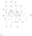
- FIGS. 3-4 show the mechanical layout of the arrangement depicted in FIG. 2 for one phase of transformer 115 according to one embodiment of the present invention.
- FIG. 3 shows a top view of transformer 115
- FIG. 4 shows a side view of transformer 115 with transformer secondary conductor 220 coupling current-limiting protection device 225 and conductor 230 coupling current-limiting protection device 225 to switchgear (not shown in FIG. 4 ).
- FIGS. 3 and 4 show only one phase (i.e., only one primary winding and secondary winding) of the three-phase system. Those skilled in the art will recognize that other phases of the three-phase system would be similar to that shown in FIGS. 3 and 4 .
- transformer 115 includes core 300 surrounded concentrically by secondary winding 210 which is surrounded concentrically by primary winding 205.
- a secondary terminal 305 is attached to secondary winding 210 which couples to transformer secondary conductor 220 ( FIG. 4 ), which couples to current-limiting protection device 225 ( FIG. 4 ).
- core 300 is an iron core with high magnetic permeability
- primary winding 205 and secondary winding 210 may be aluminum coils that may be either multi-conductor barrel or sheet conductor types
- secondary terminal 305 may be made of a copper material.
- FIG. 4 shows that transformer 115 further includes winding taps 400 that may be used to adjust the voltage output generated from the transformer. Winding taps 400 could be used to receive cables that adjust the voltage by selecting the number of turns used in the primary winding, thus changing the transformer turns ratio.
- FIG. 4 shows transformer secondary conductor 220 coupling current-limiting protection device 225 to transformer 115 via secondary terminal 305.
- FIG. 4 shows conductor 230 coupled to current-limiting protection device 225 at an end that is opposite where the device couples to transformer 115 via transformer secondary conductor 220 and secondary terminal 305.
- both transformer secondary conductor 220 and conductor 230 may be made of a copper rectangular rigid bar that facilitates coupling with current-limiting protection device 225.
- transformer secondary conductor 220 and conductor 230 have mounting holes 405 to respectively secure current-limiting protection device 225.
- Mounting holes 405 are configured to receive fasteners such as bolts, lugs, etc., that secure transformer secondary conductor 220 and conductor 230 to current-limiting protection device 225.
- FIG. 4 also shows current-limiting protection device 225 mounted vertically with respect to transformer secondary conductor 220 and conductor 230, however, those skilled in the art will recognize that the device could be mounted horizontally with respect to these conductors.
- FIGS. 1-4 are able to reduce arc flash hazard levels that may occur between the secondary windings 210 of the transformer 115 and the switchgear 130 including transition compartment 135 because current-limiting protection device 225 interrupts the fault current with the first loop of overcurrent, prior to the first current zero.
- current-limiting protection device 225 should be properly selected to provide an energy let-through that is small enough to allow less than about 40 cal/cm 2 of incident energy at the working distance.
- arc flash hazard levels are reduced at regions of a power sub-station that can have incident energy levels that are greater than about 40 cal/cm 2 , workers can safely use personal protective equipment to perform maintenance in a prescribed manner (i.e., according to safety level mandates) while compartments are still energized.
Landscapes
- Engineering & Computer Science (AREA)
- Power Engineering (AREA)
- Emergency Protection Circuit Devices (AREA)
- Regulation Of General Use Transformers (AREA)
Abstract
Description
- The present invention relates generally to power distribution systems, and more particularly to reducing arc flash hazard levels between transformer secondaries and switchgear that are utilized in a power sub-station.
- An arc flash hazard is a dangerous condition associated with the release of energy caused by an electric arc. Generally, an electric arc is formed when two conductor materials (e.g., copper) separated by a gap are shorted together, causing passage of substantial electric currents through the gap between the conductor materials. An electric arc associated with an arc flash hazard can cause very high temperatures (e.g., up to or beyond 35,000°F) to quickly occur at the conductor materials. These very high temperatures vaporize the conductor materials, creating extremely explosive pressures due to metal vaporization and rapid heating of the air in the gap by electric current passing through it. The vaporization of metal and heating of the surrounding air results in a very rapid blast due to the build-up of high pressures. The blast causes molten metal and equipment parts to violently spew from the point of the blast. People that are nearby arc flash hazards may be subject to severe bums, ruptured eardrums, collapsed lungs and forces that can violently knock them back.
- There are several approaches to remediating arc flash hazards. One approach is to use engineering methods to reduce the amount of short circuit current associated with the electric arc, as well as reduce the duration of the arc. Reducing the amount of energy associated with the electric arc and the duration of the arc corresponds to fewer injuries. Another approach to remediating arc flash hazards is to require people working on or near exposed energized conductors to wear personal protective equipment (e.g., heavy jackets, protective hoods, face shields, gloves, etc.) designed specifically for arc flash hazards. A third approach to remediating arc flash hazards involves using procedural or administrative methods to warn people of the potential for the occurrence of arc flash hazards if one is going to work on or be near exposed energized conductors that could experience an electric arc. Procedural or administrative methods may include applying warning labels on or near exposed energized conductors. For example, a typical label could state that if one is going to work on equipment having exposed energized conductors, then workers have to wear authorized personal protective equipment and maintain a predetermined distance from the conductor materials that could be subject to an arc flash hazard.
- The above-described approaches to remediating arc flash hazards are not always effective for arc flashes caused by electric arcs having an energy that is greater than 40cal/cm2. That is, engineering methods that reduce the amount of energy associated with the electric arc and the duration of the arc may not be available for use with levels greater than 40cal/cm 2. Furthermore, currently available personal protective equipment may not provide protection against blasts that can arise from energy levels that are greater than 40cal/cm2. Similarly, the hazards associated with blasts that can arise from energy levels that are greater than 40cal/cm2 essentially make the use of warning labels ineffectual for their intended purposes. Because the above-described approaches to remediating arc flash hazards are not suitable for arc flashes caused by electric arcs having an energy that is greater than 40cal/cm2 workers need to shut down the equipment and work on it while deenergized. Shutting down equipment and working on it while deenergized is not always an optimal solution, especially in facilitates where it is desirable to keep equipment operating 24 hours, seven days a week.
- In one aspect of the present invention, a system is provided. The system comprises a transformer having at least one primary winding and at least one secondary winding. Switchgear having a main circuit breaker is coupled to the transformer via the at least one secondary winding. At least one current-limiting protection device is located between the transformer and the switchgear. The at least one current-limiting protection device couples to the at least one secondary winding of the transformer. The at least one current-limiting protection device reduces arc flash hazard levels between the at least one secondary winding of the transformer and the switchgear.
- In another aspect of the present invention, an arc flash hazard reduction system is provided. In this aspect of the present invention, the arc flash hazard reduction system comprises a transformer having at least one primary winding and at least one secondary winding. Switchgear having a main circuit breaker is coupled to the transformer via the at least one secondary winding. At least one current-limiting fuse is located between the transformer and the switchgear, wherein the at least one current-limiting fuse couples to the at least one secondary winding of the transformer. The at least one current-limiting fuse reduces arc flash hazard levels between the at least one secondary winding of the transformer and the switchgear.
- In a third aspect of the present invention, a power sub-station is provided. In this aspect of the present invention, the power sub-station comprises a primary switch receiving an incoming voltage supply. A transformer has at least one primary winding and at least one secondary winding, wherein the at least one primary winding of the transformer couples to the primary switch. Switchgear having a main circuit breaker is coupled to the transformer via the at least one secondary winding. At least one current-limiting fuse is located between the transformer and the switchgear, wherein the at least one current-limiting fuse couples to the at least one secondary winding of the transformer. The at least one current-limiting fuse reduces arc flash hazard levels between the at least one secondary winding of the transformer and the switchgear.
- Various aspects and embodiments of the present invention will now be described in connection with the accompanying drawings, in which:
-
FIG. 1 is a schematic diagram of a low-voltage power sub-station; -
FIG. 2 is a schematic diagram of an arc flash hazard reduction system that is suitable for use in the low-voltage power sub-station depicted inFIG. 1 according to one embodiment of the present invention; and -
FIGS. 3-4 show the mechanical layout for one phase of the transformer depicted inFIG. 2 according to one embodiment of the present invention. - Various embodiments of the present invention are directed to an arc flash hazard reduction system for use in a power sub-station. In these embodiments, current-limiting protection devices such as current-limiting protection fuses (e.g., a high speed, high current fuse) are placed between a transformer and switchgear having a main circuit breaker, such that the current-limiting protection devices are coupled to the secondary windings of the transformer. Placing the current-limiting protection devices between the secondary windings of the transformer and the switchgear provides arc flash hazard reduction capability in a region of a power substation that is designated as an "Extreme Danger" area because it can have incident energy levels that are greater than about 40 cal/cm2. Technical effects of various embodiments of the present invention include providing arc flash hazard reduction in regions of a power sub-station that can have incident energy levels that are greater than about 40 cal/cm2. This enables workers to perform maintenance on such areas without having to shut down and deenergize equipment. Performing maintenance on Extreme Danger regions without having to shut down and deenergize equipment results in increased productivity of the power sub-station.
- In the various embodiments of the present invention as described herein, the arc flash hazard reduction system is suitable for use in a power sub-station such as a low-voltage power sub-station. Although the various embodiments of the present invention are described with respect to reducing arc flash hazard reduction levels in a low-voltage power sub-station, the embodiments of the present invention are not limited to use solely with these types of sub-stations. Those skilled in the art will recognize that the various embodiments of the present invention can be used in other power sub-stations such as medium-voltage and high-voltage sub-stations. In addition, the various embodiments of the present invention are not limited to power sub-stations. The various embodiments of the present invention may have utility in other parts of power distribution systems where it is desirable to reduce arc flash hazard reduction levels.
- Referring to the drawings,
FIG. 1 is a schematic diagram of a low-voltage power sub-station 100. As shown inFIG. 1 ,power sub-station 100 comprises aprimary side 105 that receives incoming lines from a voltage source (not shown). In particular,primary side 105 includes a primary switch 110 (e.g., a three-knife switch) that receives incoming cables that supply voltage. In one embodiment,primary switch 110 receives 13.8 kilo volts (kV) from the source. For sake of simplicity in illustrating a low-voltage power sub-station, those skilled in the art will recognize that not all features and functionalities associated withprimary side 105 are illustrated inFIG.1 . For example, those skilled in the art will appreciate thatprimary side 105 could have fuses, insulators, lightning arrestors, etc. - A
transformer 115 having at least one primary winding (not shown inFIG. 1 ) and at least one secondary winding (not shown inFIG. 1 ) is coupled toprimary side 105. Atransition compartment 120 located betweenprimary side 105 andtransformer 115 contains conductors, bus bars or cables (not shown inFIG. 1 ) that connect the primary winding(s) (not shown inFIG. 1 ) oftransformer 115 to conductors, bus bars or cables (not shown inFIG. 1 ) associated withprimary side 105.Transformer 115 receives the voltage supplied fromprimary side 105 and reduces it to a lower voltage and provides it to asecondary side 125. As shown inFIG. 1 ,secondary side 125 includes switchgear having amain circuit breaker 130 viatransition compartment 135.Transition compartment 135 contains conductors, bus bars or cables (not shown inFIG. 1 ) that connect the secondary winding(s) (not shown inFIG. 1 ) oftransformer 115 to conductors, bus bars or cables (not shown inFIG. 1 ) associated withswitchgear 130. In one embodiment,transformer 115 reduces 13.8 kV provided fromprimary side 105 to 480V and transfers it to switchgear 130 viatransition compartment 135. - Under normal operating conditions the main circuit breaker in
switchgear 130 is closed so that the power supply received fromtransformer 115 is distributed to one of a variety of loads. If the main circuit breaker inswitchgear 130 determines that there is a short circuit current flowing in the switchgear then it opens up to interrupt the short circuit current. As shown inFIG. 1 , the loads that receive power supplied fromswitchgear 130 include alighting load 140, anair compressor load 145, a heat/ventilating/air-conditioning (HVAC)load 150 and a motor control center (MCC)load 155. Although not shown inFIG. 1 , each of these loads will have their own internal circuit breaker that can interrupt short circuit flowing in these loads. Those skilled in the art will recognize thatlighting load 140,air compressor load 145, heat/ventilating/air-conditioning (HVAC)load 150 and motor control center (MCC)load 155 are only examples of possible loads and thatpower sub-station 100 can have additional loads or even fewer loads than shown inFIG. 1 . -
FIG. 1 shows thatsecondary side 125 ofpower sub-station 100 further includes acontrol room 160 and a tie breaker 165. In one embodiment,control room 160 has meters that provide an indication of voltage and current in various parts of the equipment formingpower sub-station 100. In addition,control room 160 may have the capability to perform remote monitoring and diagnostics of power-substation 100. Those skilled in the art will recognize that these are only a few examples of functionalities that can be performed incontrol room 160 and is not meant to cover all possible functions. Tie breaker 165 provides a connection to another sub-station in case a back-up is needed. For example, if some type of fault arises inpower substation 100 and it prevents the supply of power tolighting load 140,air compressor load 145, heat/ventilatinglair-conditioning load (HVAC) 150 and motor control center (MCC)load 155, then tie breaker 165 could be closed so that power from the back-up sub-station (not shown inFIG. 1 ) could be supplied to the loads. Those skilled in the art will recognize thatsecondary side 125 can have additional components attached thereto and thatcontrol room 160 and tie breaker 165 are only a couple of examples of components that can be part of a secondary side of a power sub-station. - As shown by an arc
flash hazard symbol 170 inFIG. 1 ,transition compartment 135 andswitchgear 130 are regions withinpower sub-station 100 that may have incident energies greater than about 40cal/cm2 that cannot be remediated by personal protective equipment and alabel 175 that warns of the extreme dangers associated with these types of arc flash hazards. As noted above,primary side 105 would have fuses located betweenprimary switch 110 and the primary winding(s) (not shown inFIG. 1 ) oftransformer 115 to protect against high voltages, but these fuses are neither fast enough nor sensitive enough to protect against arc flash hazards that could arise between the secondary winding(s) (not shown inFIG. 1 ) oftransformer 115 andtransition compartment 135 andswitchgear 130. - Various embodiments of the present invention have addressed arc flash hazards that can arise between the secondary windings (not shown in
FIG. 1 ) oftransformer 115 andtransition compartment 135 andswitchgear 130 by placing current-limiting protection devices such as current-limiting protection fuses (e.g., a high speed, high current fuse) between the secondary windings of the transformer and theconductor coupling transformer 115 totransition compartment 135 andswitchgear 130. Placement of current-limiting protection devices in this location provides the capability to reduce arc flash hazards that can arise in the region includingtransition compartment 135 andswitchgear 130 and that can have incident energy levels that are greater than about 40 cal/cm2. As mentioned above, current-limiting protection devices (e.g., fuses) have been used on theprimary side 105 betweenprimary switch 110 and the primary winding(s) oftransformer 115 to protect against high voltages, but these devices are neither fast enough nor sensitive enough to protect against arc flash hazards that could arise between the secondary winding(s) oftransformer 115 andtransition compartment 135 andswitchgear 130. -
FIG. 2 is a schematic circuit diagram of an arc flashhazard reduction system 200 showing the details of the current-limiting protection devices in relation to transformer 115 (FIG. 1 ) and transition compartment 135 (FIG. 1 ) and switchgear 130 (FIG. 1 ). As shown inFIG. 2 ,transformer 115 includesprimary windings 205 andsecondary windings 210 placed about acore 300. In this embodiment,transformer 115 is a three-phase system having three legs (i.e., three pairs of primary and secondary windings all on the same core). Those skilled in the art will recognize that other types of transformers could be used as well as other three-phase transformers that have more than three legs (e.g., five legs). Transformerprimary conductors 215 coupleprimary windings 205 oftransformer 115 to primary switch 110 (FIG. 1 ) of primary side 105 (FIG. 1 ). Transformersecondary conductors 220 couplesecondary windings 210 oftransformer 115 to current-limitingprotection devices 225.Conductors 230 couple current-limitingprotection devices 225 to amain circuit breaker 235 located in switchgear 130 (FIG. 1 ) via transition component 135 (FIG. 1 ). - In one embodiment, current-limiting
protection devices 225 comprise a current-limiting fuse. One example of a current-limiting fuse that is suitable for use in the various embodiments of the present invention is any commercially available high speed, high current fuse. Square body fuses such as a FU170M6621 fuse (550V, 2000A, Clearing I2t=6.35x10⁶ A2 sec) sold by Cooper Bussman is one example of a commercially available high speed, high current fuse that may be used with various embodiments of the present invention. Those skilled in the art will recognize that there are other commercially available high speed, high current fuses of comparable size, rating (e.g., 800A, 1200A, 1600A and 2400A) and clearing that may be used as a current-limiting protection device in various embodiments of the present invention. - The various embodiments of the present invention are not limited to using current-limiting fuses. Those skilled in the art will recognize that other current-limiting protection devices may be suitable for use with the various embodiments of the present invention. For example, current-limiting circuit breakers, "Is limiters" or "CLIP" devices may be used, as long as they can provide the necessary degree of current limitation.
- As shown in
FIG. 2 , current-limitingprotection devices 225 are coupled directly onsecondary windings 210 oftransformer 115 via transformersecondary conductors 220. Minimizing transformersecondary conductors 220 so that current-limitingprotection devices 225 are located at a predetermined minimal distance tosecondary windings 210, minimizes the amount of exposed area that is susceptible to the high levels of incident energy that creates the arc flash hazards. In one embodiment, a predetermined minimal distance between current-limitingprotection devices 225 andsecondary windings 210 is less than about 10 centimeters (cm). In another embodiment, a predetermined minimal distance between current-limitingprotection devices 225 andsecondary windings 210 may be in the range of about 5 cm to about 10 cm. Those skilled in the art will recognize that this predetermined minimal distance is only an example and that other amounts are within the scope of the various embodiments of the present invention. -
FIGS. 3-4 show the mechanical layout of the arrangement depicted inFIG. 2 for one phase oftransformer 115 according to one embodiment of the present invention. In particular,FIG. 3 shows a top view oftransformer 115, whileFIG. 4 shows a side view oftransformer 115 with transformersecondary conductor 220 coupling current-limitingprotection device 225 andconductor 230 coupling current-limitingprotection device 225 to switchgear (not shown inFIG. 4 ). For ease of illustration,FIGS. 3 and 4 show only one phase (i.e., only one primary winding and secondary winding) of the three-phase system. Those skilled in the art will recognize that other phases of the three-phase system would be similar to that shown inFIGS. 3 and 4 . - As shown in
FIG. 3 ,transformer 115 includescore 300 surrounded concentrically by secondary winding 210 which is surrounded concentrically by primary winding 205. Asecondary terminal 305 is attached to secondary winding 210 which couples to transformer secondary conductor 220 (FIG. 4 ), which couples to current-limiting protection device 225 (FIG. 4 ). In one embodiment,core 300 is an iron core with high magnetic permeability, primary winding 205 and secondary winding 210 may be aluminum coils that may be either multi-conductor barrel or sheet conductor types, whilesecondary terminal 305 may be made of a copper material. -
FIG. 4 shows thattransformer 115 further includes windingtaps 400 that may be used to adjust the voltage output generated from the transformer. Winding taps 400 could be used to receive cables that adjust the voltage by selecting the number of turns used in the primary winding, thus changing the transformer turns ratio. -
FIG. 4 shows transformersecondary conductor 220 coupling current-limitingprotection device 225 totransformer 115 viasecondary terminal 305. In addition,FIG. 4 showsconductor 230 coupled to current-limitingprotection device 225 at an end that is opposite where the device couples totransformer 115 via transformersecondary conductor 220 andsecondary terminal 305. In one embodiment, both transformersecondary conductor 220 andconductor 230 may be made of a copper rectangular rigid bar that facilitates coupling with current-limitingprotection device 225. As shown inFIG. 4 , transformersecondary conductor 220 andconductor 230 have mountingholes 405 to respectively secure current-limitingprotection device 225. Mountingholes 405 are configured to receive fasteners such as bolts, lugs, etc., that secure transformersecondary conductor 220 andconductor 230 to current-limitingprotection device 225.FIG. 4 also shows current-limitingprotection device 225 mounted vertically with respect to transformersecondary conductor 220 andconductor 230, however, those skilled in the art will recognize that the device could be mounted horizontally with respect to these conductors. - The configurations illustrated in
FIGS. 1-4 are able to reduce arc flash hazard levels that may occur between thesecondary windings 210 of thetransformer 115 and theswitchgear 130 includingtransition compartment 135 because current-limitingprotection device 225 interrupts the fault current with the first loop of overcurrent, prior to the first current zero. Those skilled in the art will recognize that current-limitingprotection device 225 should be properly selected to provide an energy let-through that is small enough to allow less than about 40 cal/cm2 of incident energy at the working distance. Because arc flash hazard levels are reduced at regions of a power sub-station that can have incident energy levels that are greater than about 40 cal/cm2, workers can safely use personal protective equipment to perform maintenance in a prescribed manner (i.e., according to safety level mandates) while compartments are still energized. - While the disclosure has been particularly shown and described in conjunction with a preferred embodiment thereof, it will be appreciated that variations and modifications will occur to those skilled in the art. Therefore, it is to be understood that the appended claims are intended to cover all such modifications and changes as fall within the true spirit of the disclosure.
- Various aspects and embodiments of the present invention are defined by the following numbered clauses:
- 1. A system, comprising:
- a transformer having at least one primary winding and at least one secondary winding;
- switchgear having a main circuit breaker coupled to the transformer via the at least one secondary winding; and
- at least one current-limiting protection device located between the transformer and the switchgear, wherein the at least one current-limiting protection device couples to the at least one secondary winding of the transformer, the at least one current-limiting protection device reducing arc flash hazard levels between the at least one secondary winding of the transformer and the switchgear.
- 2. The system according to clause 1, wherein the at least one current-limiting protection device comprises a high speed, high current fuse.
- 3. The system according to any preceding clause, further comprising a transformer secondary conductor coupling one end of the at least one current-limiting protection device to the at least one secondary winding of the transformer.
- 4. The system according to any preceding clause, further comprising a conductor coupling the at least one current-limiting protection device to the main circuit breaker of the switchgear, wherein the conductor couples to the at least one current-limiting protection device at an end opposite that couples the at least one current-limiting protection device to the at least one secondary winding of the transformer.
- 5. The system according to any preceding clause, wherein the transformer secondary conductor and the conductor each comprise a mounting hole to facilitate fastening with the at least one current-limiting protection device.
- 6. The system according to any preceding clause, wherein the at least one current-limiting protection device couples to the at least one secondary winding of the transformer at a predetermined minimal distance.
- 7. The system according to any preceding clause, further comprising a plurality of loads coupled to the switchgear.
- 8. An arc flash hazard reduction system, comprising:
- a transformer having at least one primary winding and at least one secondary winding;
- switchgear having a main circuit breaker coupled to the transformer via the at least one secondary winding; and
- at least one current-limiting fuse located between the transformer and the switchgear, wherein the at least one current-limiting fuse couples to the at least one secondary winding of the transformer, the at least one current-limiting fuse reducing arc flash hazard levels between the at least one secondary winding of the transformer and the switchgear.
- 9. The arc flash hazard reduction system according to any preceding clause, wherein the at least one current-limiting fuse comprises a high speed, high current fuse.
- 10. The arc flash hazard reduction system according to any preceding clause, further comprising a transformer secondary conductor coupling one end of the at least one current-limiting fuse to the at least one secondary winding of the transformer.
- 11. The arc flash hazard reduction system according to any preceding clause, further comprising a conductor coupling the at least one current-limiting fuse to the main circuit breaker of the switchgear, wherein the conductor couples to the at least one current-limiting fuse at an end opposite that couples the at least one current-limiting fuse to the at least one secondary winding of the transformer.
- 12. The arc flash hazard reduction system according to any preceding clause, wherein the at least one current-limiting protection device reduces arc flash hazards having incident energy levels that are greater than about 40 cal/cm2.
- 13. A power sub-station, comprising:
- a primary switch receiving an incoming voltage supply;
- a transformer having at least one primary winding and at least one secondary winding, wherein the at least one primary winding of the transformer couples to the primary switch;
- switchgear having a main circuit breaker coupled to the transformer via the at least one secondary winding; and
- at least one current-limiting fuse located between the transformer and the switchgear, wherein the at least one current-limiting fuse couples to the at least one secondary winding of the transformer, the at least one current-limiting fuse reducing arc flash hazard levels between the at least one secondary winding of the transformer and the switchgear.
- 14. The power sub-station according to any preceding clause, wherein the at least one current-limiting fuse comprises a high speed, high current fuse.
- 15. The power sub-station according to any preceding clause, comprising a first transition compartment having a transformer primary conductor coupling one end of the primary switch to the at least one primary winding of the transformer, wherein the transformer primary conductor couples to the primary switch at an end opposite the end that receives the incoming voltage supply.
- 16. The power sub-station according to any preceding clause, further comprising a second transition compartment having a transformer secondary conductor coupling one end of the at least one current-limiting fuse to the at least one secondary winding of the transformer.
- 17. The power sub-station according to any preceding clause, wherein the second transition compartment further comprises a conductor coupling the at least one current-limiting fuse to the main circuit breaker of the switchgear, wherein the conductor couples to the at least one current-limiting fuse at an end opposite that couples the at least one current-limiting fuse to the at least one secondary winding of the transformer.
- 18. The power sub-station according to any preceding clause, wherein the transformer secondary conductor and the conductor each comprise a mounting hole to facilitate fastening with the at least one current-limiting fuse.
- 19. The power sub-station according to any preceding clause, wherein the at least one current-limiting fuse couples to the at least one secondary winding of the transformer at a predetermined minimal distance.
- 20. The power sub-station according to any preceding clause, further comprising a plurality of loads coupled to the switchgear.
Claims (10)
- A system, comprising:a transformer (115) having at least one primary winding (205) and at least one secondary winding (210);switchgear (130) having a main circuit breaker (235) coupled to the transformer (115) via the at least one secondary winding (210); andat least one current-limiting protection device (225) located between the transformer (115) and the switchgear (130), wherein the at least one current-limiting protection device (225) couples to the at least one secondary winding (210) of the transformer (115), the at least one current-limiting protection device (115) reducing arc flash hazard levels between the at least one secondary winding (210) of the transformer (115) and the switchgear (130).
- The system according to claim 1, wherein the at least one current-limiting protection device (225) comprises a high speed, high current fuse.
- The system according to any preceding claim, further comprising a transformer secondary conductor (220) coupling one end of the at least one current-limiting protection device (225) to the at least one secondary winding (210) of the transformer (115).
- The system according to any preceding claim, further comprising a conductor (230) coupling the at least one current-limiting protection device (225) to the main circuit breaker (235) of the switchgear (130), wherein the conductor (230) couples to the at least one current-limiting protection device (225) at an end opposite that couples the at least one current-limiting protection device (225) to the at least one secondary winding (210) of the transformer (115).
- The system according to claim 4, wherein the transformer secondary conductor (220) and the conductor (230) each comprise a mounting hole (405) to facilitate fastening with the at least one current-limiting protection device (225).
- The system according to any preceding claim, wherein the at least one current-limiting protection device (225) couples to the at least one secondary winding (210) of the transformer (115) at a predetermined minimal distance.
- An arc flash hazard reduction system, comprising:a transformer (115) having at least one primary winding (205) and at least one secondary winding (210);switchgear (130) having a main circuit breaker (235) coupled to the transformer (115) via the at least one secondary winding (210); andat least one current-limiting fuse (225) located between the transformer (115) and the switchgear (130), wherein the at least one current-limiting fuse (225) couples to the at least one secondary winding (210) of the transformer (115), the at least one current-limiting fuse (225) reducing arc flash hazard levels between the at least one secondary winding (210) of the transformer (115) and the switchgear (130).
- The arc flash hazard reduction system according to claim 7, wherein the at least one current-limiting protection device (225) reduces arc flash hazards having incident energy levels that are greater than about 40 cal/cm2.
- A power sub-station (100), comprising:a primary switch (110) receiving an incoming voltage supply;a transformer (115) having at least one primary winding (205) and at least one secondary winding (220), wherein the at least one primary winding (205) of the transformer (115) couples to the primary switch (110);switchgear (130) having a main circuit breaker (235) coupled to the transformer (115) via the at least one secondary winding (210); andat least one current-limiting fuse (225) located between the transformer (115) and the switchgear (130), wherein the at least one current-limiting fuse (225) couples to the at least one secondary winding (210) of the transformer (115), the at least one current-limiting fuse (225) reducing arc flash hazard levels between the at least one secondary winding (210) of the transformer (115) and the switchgear (130).
- The power sub-station (100) according to claim 9, further comprising a plurality of loads (140, 145, 150, 155) coupled to the switchgear (130).
Applications Claiming Priority (1)
| Application Number | Priority Date | Filing Date | Title |
|---|---|---|---|
| US12/761,587 US20110255199A1 (en) | 2010-04-16 | 2010-04-16 | Arc flash hazard reduction for transformer secondaries |
Publications (2)
| Publication Number | Publication Date |
|---|---|
| EP2381453A2 true EP2381453A2 (en) | 2011-10-26 |
| EP2381453A3 EP2381453A3 (en) | 2017-04-19 |
Family
ID=44545448
Family Applications (1)
| Application Number | Title | Priority Date | Filing Date |
|---|---|---|---|
| EP11161634.8A Withdrawn EP2381453A3 (en) | 2010-04-16 | 2011-04-08 | Arc flash hazard reduction for transformer secondaries |
Country Status (3)
| Country | Link |
|---|---|
| US (1) | US20110255199A1 (en) |
| EP (1) | EP2381453A3 (en) |
| JP (1) | JP2011229376A (en) |
Cited By (1)
| Publication number | Priority date | Publication date | Assignee | Title |
|---|---|---|---|---|
| US9537438B2 (en) | 2015-01-12 | 2017-01-03 | Cummins Power Generation, Ip, Inc. | Buss potential isolation module |
Families Citing this family (2)
| Publication number | Priority date | Publication date | Assignee | Title |
|---|---|---|---|---|
| CA2980153C (en) | 2015-03-24 | 2024-05-07 | Eaton Corporation | Arc flash mitigation switch for quenching external arc faults in low voltage switchgear |
| CN116581712B (en) * | 2023-07-07 | 2024-08-06 | 深圳市首航新能源股份有限公司 | Energy storage system |
Family Cites Families (6)
| Publication number | Priority date | Publication date | Assignee | Title |
|---|---|---|---|---|
| NL1015766C2 (en) * | 2000-07-21 | 2002-01-22 | Koninkl Kpn Nv | System for overvoltage protection. |
| JPS5843363Y2 (en) * | 1978-10-26 | 1983-10-01 | 株式会社東芝 | Air-cooled transformer device with protector fuse |
| JPS6038921B2 (en) * | 1979-05-04 | 1985-09-03 | 株式会社日立製作所 | Spot network power receiving equipment |
| FR2782409B1 (en) * | 1998-08-14 | 2002-11-29 | Schneider Electric Ind Sa | UNDERWATER TRANSFORMER SELF-PROTECTED BY A DEVICE INCLUDING A CIRCUIT BREAKER AND FUSES |
| US7599161B2 (en) * | 2006-12-29 | 2009-10-06 | General Electric Company | Relay device and corresponding method |
| US8300382B2 (en) * | 2010-01-30 | 2012-10-30 | Jack Jumper, Llc | Portable transformer with safety interlock |
-
2010
- 2010-04-16 US US12/761,587 patent/US20110255199A1/en not_active Abandoned
-
2011
- 2011-04-08 EP EP11161634.8A patent/EP2381453A3/en not_active Withdrawn
- 2011-04-12 JP JP2011087831A patent/JP2011229376A/en active Pending
Non-Patent Citations (1)
| Title |
|---|
| None |
Cited By (1)
| Publication number | Priority date | Publication date | Assignee | Title |
|---|---|---|---|---|
| US9537438B2 (en) | 2015-01-12 | 2017-01-03 | Cummins Power Generation, Ip, Inc. | Buss potential isolation module |
Also Published As
| Publication number | Publication date |
|---|---|
| US20110255199A1 (en) | 2011-10-20 |
| JP2011229376A (en) | 2011-11-10 |
| EP2381453A3 (en) | 2017-04-19 |
Similar Documents
| Publication | Publication Date | Title |
|---|---|---|
| US20170025849A1 (en) | Controlled Switching Devices and Method of Using the Same | |
| EP2381453A2 (en) | Arc flash hazard reduction for transformer secondaries | |
| Prigmore et al. | Triggered current limiters—Their arc flash mitigation and damage limitation capabilities | |
| CN102027652B (en) | Transformation substation | |
| Smith | Performing detailed power system studies for designing and analyzing electrical distribution systems-Power system studies for cement plants | |
| Durocher et al. | Arc flash safety compliance: A journey toward electrical workplace safety and production reliability | |
| Buff et al. | Application of existing technologies to reduce arc-flash hazards | |
| Dugan | Reducing the flash hazard | |
| Das | Design aspects of industrial distribution systems to limit arc flash hazard | |
| Das | Protection planning and system design to reduce arc flash incident energy in a multi-voltage level distribution system to 8 CAL/CM 2 (HRC 2) or less–part II: Analysis | |
| EP2905852B1 (en) | Electrical low-voltage power distribution equipment | |
| Hopper et al. | Distribution equipment modernization to reduce arc flash hazards | |
| Sidhu et al. | Selection of optimum circuit breaker for a low-voltage industrial power distribution system | |
| Durocher | Considerations in unit substation design to optimize reliability and electrical workplace safety | |
| Einhorn | The protection of low-voltage installations by means of miniature circuit breakers and HRC Fuses | |
| Kobet | Evaluation of 13kV dry-type shunt reactor protection following near-miss | |
| Smith | Power system studies for cement plants | |
| Paul et al. | Ground fault current protection of a 480Y/277V power system compliance with NEC design requirements | |
| Larsen et al. | Selective coordination in low-voltage power distribution systems: Is the level important? | |
| Neeser | Short-circuit current ratings: Key considerations for the safety of commercial and industrial electrical systems | |
| Bishop et al. | Overcurrent protection device miscoordination issues that result in plant outages and costly down time | |
| Zaidi | Power Flow Study of a Compressor Gas Station | |
| Durocher | Unit substation design | |
| Harris et al. | High-Voltage Switching Equipment | |
| Whitt | Trends and practices in grounding and ground fault protection using static devices |
Legal Events
| Date | Code | Title | Description |
|---|---|---|---|
| AK | Designated contracting states |
Kind code of ref document: A2 Designated state(s): AL AT BE BG CH CY CZ DE DK EE ES FI FR GB GR HR HU IE IS IT LI LT LU LV MC MK MT NL NO PL PT RO RS SE SI SK SM TR |
|
| AX | Request for extension of the european patent |
Extension state: BA ME |
|
| PUAI | Public reference made under article 153(3) epc to a published international application that has entered the european phase |
Free format text: ORIGINAL CODE: 0009012 |
|
| PUAL | Search report despatched |
Free format text: ORIGINAL CODE: 0009013 |
|
| AK | Designated contracting states |
Kind code of ref document: A3 Designated state(s): AL AT BE BG CH CY CZ DE DK EE ES FI FR GB GR HR HU IE IS IT LI LT LU LV MC MK MT NL NO PL PT RO RS SE SI SK SM TR |
|
| AX | Request for extension of the european patent |
Extension state: BA ME |
|
| RIC1 | Information provided on ipc code assigned before grant |
Ipc: H02H 7/04 20060101ALI20170311BHEP Ipc: H01F 27/40 20060101AFI20170311BHEP Ipc: H02H 9/02 20060101ALI20170311BHEP |
|
| STAA | Information on the status of an ep patent application or granted ep patent |
Free format text: STATUS: THE APPLICATION IS DEEMED TO BE WITHDRAWN |
|
| 18D | Application deemed to be withdrawn |
Effective date: 20171020 |