EP2381221A2 - Methods And Systems Involving Viewing Angles In Aircraft Displays - Google Patents
Methods And Systems Involving Viewing Angles In Aircraft Displays Download PDFInfo
- Publication number
- EP2381221A2 EP2381221A2 EP11154866A EP11154866A EP2381221A2 EP 2381221 A2 EP2381221 A2 EP 2381221A2 EP 11154866 A EP11154866 A EP 11154866A EP 11154866 A EP11154866 A EP 11154866A EP 2381221 A2 EP2381221 A2 EP 2381221A2
- Authority
- EP
- European Patent Office
- Prior art keywords
- aircraft
- graphical representation
- environment
- point
- environmental data
- Prior art date
- Legal status (The legal status is an assumption and is not a legal conclusion. Google has not performed a legal analysis and makes no representation as to the accuracy of the status listed.)
- Withdrawn
Links
Images


Classifications
-
- G—PHYSICS
- G01—MEASURING; TESTING
- G01C—MEASURING DISTANCES, LEVELS OR BEARINGS; SURVEYING; NAVIGATION; GYROSCOPIC INSTRUMENTS; PHOTOGRAMMETRY OR VIDEOGRAMMETRY
- G01C23/00—Combined instruments indicating more than one navigational value, e.g. for aircraft; Combined measuring devices for measuring two or more variables of movement, e.g. distance, speed or acceleration
-
- G—PHYSICS
- G01—MEASURING; TESTING
- G01S—RADIO DIRECTION-FINDING; RADIO NAVIGATION; DETERMINING DISTANCE OR VELOCITY BY USE OF RADIO WAVES; LOCATING OR PRESENCE-DETECTING BY USE OF THE REFLECTION OR RERADIATION OF RADIO WAVES; ANALOGOUS ARRANGEMENTS USING OTHER WAVES
- G01S13/00—Systems using the reflection or reradiation of radio waves, e.g. radar systems; Analogous systems using reflection or reradiation of waves whose nature or wavelength is irrelevant or unspecified
- G01S13/88—Radar or analogous systems specially adapted for specific applications
- G01S13/93—Radar or analogous systems specially adapted for specific applications for anti-collision purposes
- G01S13/933—Radar or analogous systems specially adapted for specific applications for anti-collision purposes of aircraft or spacecraft
- G01S13/935—Radar or analogous systems specially adapted for specific applications for anti-collision purposes of aircraft or spacecraft for terrain-avoidance
-
- G—PHYSICS
- G01—MEASURING; TESTING
- G01S—RADIO DIRECTION-FINDING; RADIO NAVIGATION; DETERMINING DISTANCE OR VELOCITY BY USE OF RADIO WAVES; LOCATING OR PRESENCE-DETECTING BY USE OF THE REFLECTION OR RERADIATION OF RADIO WAVES; ANALOGOUS ARRANGEMENTS USING OTHER WAVES
- G01S7/00—Details of systems according to groups G01S13/00, G01S15/00, G01S17/00
- G01S7/02—Details of systems according to groups G01S13/00, G01S15/00, G01S17/00 of systems according to group G01S13/00
- G01S7/04—Display arrangements
- G01S7/06—Cathode-ray tube displays or other two dimensional or three-dimensional displays
- G01S7/20—Stereoscopic displays; Three-dimensional [3D] displays; Pseudo-3D displays
-
- G—PHYSICS
- G01—MEASURING; TESTING
- G01S—RADIO DIRECTION-FINDING; RADIO NAVIGATION; DETERMINING DISTANCE OR VELOCITY BY USE OF RADIO WAVES; LOCATING OR PRESENCE-DETECTING BY USE OF THE REFLECTION OR RERADIATION OF RADIO WAVES; ANALOGOUS ARRANGEMENTS USING OTHER WAVES
- G01S7/00—Details of systems according to groups G01S13/00, G01S15/00, G01S17/00
- G01S7/02—Details of systems according to groups G01S13/00, G01S15/00, G01S17/00 of systems according to group G01S13/00
- G01S7/04—Display arrangements
- G01S7/06—Cathode-ray tube displays or other two dimensional or three-dimensional displays
- G01S7/24—Cathode-ray tube displays or other two dimensional or three-dimensional displays the display being orientated or displaced in accordance with movement of object carrying the transmitting and receiving apparatus, e.g. true-motion radar
-
- G—PHYSICS
- G08—SIGNALLING
- G08G—TRAFFIC CONTROL SYSTEMS
- G08G5/00—Traffic control systems for aircraft
- G08G5/20—Arrangements for acquiring, generating, sharing or displaying traffic information
- G08G5/21—Arrangements for acquiring, generating, sharing or displaying traffic information located onboard the aircraft
-
- G—PHYSICS
- G08—SIGNALLING
- G08G—TRAFFIC CONTROL SYSTEMS
- G08G5/00—Traffic control systems for aircraft
- G08G5/70—Arrangements for monitoring traffic-related situations or conditions
- G08G5/74—Arrangements for monitoring traffic-related situations or conditions for monitoring terrain
Definitions
- the subject matter disclosed herein relates to systems and methods involving aircraft control.
- Many aircraft include displays that present visual representations of the surrounding environment. These representations are particularly useful during low visibility operations. In landing operations, a visual representation of the surrounding environment from the perspective of a pilot may not provide sufficient information for a pilot to effectively and safely land the aircraft.
- a method for presenting environmental data includes receiving environmental data from a sensor, processing the data to generate a graphical representation of the environment, wherein the view point of the graphical representation of the environment is a distance (d) and an angle ( ⁇ ) relative to a point in an aircraft, and presenting the graphical representation of the environment to a user on a display.
- a system for presenting environmental data includes a sensor operative to sense environmental data, a display, and a processor operative to receive environmental data from the sensor, generate a graphical representation of the environment, wherein the view point of the graphical representation of the environment is a distance (d) and an angle ( ⁇ ) relative to a point in an aircraft, and output the graphical representation of the environment to the display.
- a computer program product for presenting environmental data
- the computer program product having a storage medium readable by a processing circuit and operative to store instructions for execution by the processing circuit for implementing the method including receiving environmental data from a sensor, processing the data to generate a graphical representation of the environment, wherein the view point of the graphical representation of the environment is a distance (d) and an angle ( ⁇ ) relative to a point in an aircraft, and presenting the graphical representation of the environment to a user on a display.
- FIG. 1 illustrates an example of an aircraft approaching a landing area.
- FIG. 2 illustrates another example of the aircraft approaching the landing area.
- FIG. 3 illustrates an exemplary embodiment of a system of the aircraft.
- FIG. 4 illustrates an exemplary embodiment of an image output by the system of FIG. 3 .
- FIG. 5 illustrates a side view of the aircraft.
- FIG. 6 illustrates another exemplary embodiment of an image of the system of FIG. 3 .
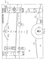
- FIG. 1 illustrates an example of an aircraft 100 approaching a landing area 101 on a surface 103 defined by a circular line 404.
- the aircraft 100 is following a path 102.
- the point 105 illustrates the position of the aircraft relative to the surface 103.
- An operator or user in the aircraft 100 has a line of sight 104 that allows the operator to view the landing area 101.
- FIG. 2 illustrates the aircraft 100 as the aircraft 100 has descended closer to the landing area 101 along the path 102.
- the aircraft 100 has pitched up for landing; and the pitch of the aircraft has increased the angle of the line of sight 104 such that the operator cannot view the entire landing area 101.
- FIG. 3 illustrates an exemplary embodiment of a control system 300 of the aircraft 100 (of FIG. 1 ).
- the aircraft 100 may include any type of aircraft such as, for example, a rotary or fixed wing aircraft.
- the aircraft 100 may be operated by, for example, an operator 310 in the aircraft 100 or an operator in a remote location.
- the system 300 includes a control area 312 having input devices 306 and a display device 304.
- the system 300 also includes a processor 302 communicatively connected to a memory 308, the display device 304, input devices 306, and sensors 314.
- the sensors 314 may include, for example, accelerometers, gyro-devices devices, or imaging devices such as radar, lasers, sonar, or other types of imaging devices including terrain data that is stored in the memory 308.
- the operator 310 is presented with an image of the surrounding environment on the display device 304.
- the image may be rendered from, for example imaging data from the sensor 314.
- FIG. 4 illustrates an exemplary embodiment of an image 400 that may be presented to the operator 310 (of FIG. 3 ) in the display device 304 (of FIG. 3 ).
- the image 400 depicts the environment in real time from the perspective of the position of the operator 310 as if the operator were in the cockpit of the aircraft 100 and viewing the environment through a canopy of the aircraft.
- the image 400 includes a variety of flight data and a representation of the surface 103 having a variety of obstacles 402.
- the landing area 101 is defined by a circular line 404. In the illustrated image 400, portions of the landing area 101 are not shown to the operator 310.
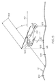
- FIG. 5 illustrates a side view of the aircraft 100, landing area 101, and the circular line 404.
- a view point 502 is shown that is a distance (d) at an angle ( ⁇ ) relative to a horizontal line 501 from a reference point 503 in the aircraft 100.
- the processor 302 receives image data from the sensors 314.
- the processor 302 processes the image data from the sensors 314 and displays the image data in the display device 304 from the view point 502 that is outside of the aircraft 100.
- the resultant image from the view point 502 depicts a graphical representation of the aircraft 100 and the surrounding environment including the landing area 101 and the circular line 404, the position of the aircraft 100 relative to the surface 103 shown by point 105, and the position of the circumference of the main rotor of the aircraft 100 relative to the surface 103 represented by a circular line 602.
- Moving the viewpoint of the operator to the view point 502 allows the operator 310 to view the location of the landing area 101 and determine whether undesirable obstructions are present in the landing area, and view the location of the aircraft 100 relative to the landing area.
- the distance (d) is between 30 and 100 meters from the reference point 503 and the angle ( ⁇ ) is between 3 degrees and 30 degrees; however any distance (d) or angle ( ⁇ ) may be used.
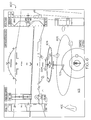
- FIG. 6 illustrates an exemplary embodiment of an image 600 that may be presented to the operator 310 in the display 304.
- the image 600 is shown from the view point 502 (of FIG. 5 ) as if the operator 310 is positioned at the view point 502.
- the image 600 includes a graphical depiction of the aircraft 100 shown by the T-shape 604, a graphical depiction of the circumference of a main rotor of the aircraft 100 shown by the circular line 602, a graphical depiction of the position of the aircraft 100 over the surface 103 (point 105), and the landing area 101 defined by the circular line 404.
- the circular lines 602 and 404 are conformable to the contours and features of the surface 103.
- Example embodiments of the present invention may be implemented, in software, for example, as any suitable computer program.
- a program in accordance with one or more example embodiments of the present invention may be a computer program product causing a computer to execute one or more of the example methods described herein: a method for simulating arbitrary software and/or unmodified code directly on a host processor.
- the computer program product may include a computer-readable medium having computer program logic or code portions embodied thereon for enabling a processor of the apparatus to perform one or more functions in accordance with one or more of the example methodologies described above.
- the computer program logic may thus cause the processor to perform one or more of the example methodologies, or one or more functions of a given methodology described herein.
- the computer-readable storage medium may be a built-in medium installed inside a computer main body or removable medium arranged so that it can be separated from the computer main body.
- Examples of the built-in medium include, but are not limited to, rewriteable non-volatile memories, such as RAMs, ROMs, flash memories, and hard disks.
- Examples of a removable medium may include, but are not limited to, optical storage media such as CD-ROMs and DVDs; magneto-optical storage media such as MOs; magnetism storage media such as floppy disks (trademark), cassette tapes, and removable hard disks; media with a built-in rewriteable non-volatile memory such as memory cards; and media with a built-in ROM, such as ROM cassettes.
- These programs may also be provided in the form of an externally supplied propagated signal and/or a computer data signal (e.g., wireless or terrestrial) embodied in a carrier wave.
- the computer data signal embodying one or more instructions or functions of an example methodology may be carried on a carrier wave for transmission and/or reception by an entity that executes the instructions or functions of the example methodology.
- the functions or instructions of the example embodiments may be implemented by processing one or more code segments of the carrier wave, for example, in a computer, where instructions or functions may be executed for simulating arbitrary software and/or unmodified code directly on a host processor, in accordance with example embodiments of the present invention.
- Such programs when recorded on computer-readable storage media, may be readily stored and distributed.
- the storage medium as it is read by a computer, may enable the simulation of arbitrary software and/or unmodified code directly on a host processor, in accordance with the example embodiments of the present invention.
- Example embodiments of the present invention being thus described, it will be obvious that the same may be varied in many ways.
- the methods according to example embodiments of the present invention may be implemented in hardware and/or software.
- the hardware/software implementations may include a combination of processor(s) and article(s) of manufacture.
- the article(s) of manufacture may further include storage media and executable computer program(s), for example, a computer program product stored on a computer readable medium.
- the executable computer program(s) may include the instructions to perform the described operations or functions.
- the computer executable program(s) may also be provided as part of externally supplied propagated signal(s).
- example embodiments of the present invention have been discussed herein with regard to specific applications and/or implementations, it will be understood that example embodiments may be utilized in, for example, in firm ASIC chip design or implemented in traditional circuitry.
Landscapes
- Engineering & Computer Science (AREA)
- Radar, Positioning & Navigation (AREA)
- Remote Sensing (AREA)
- Physics & Mathematics (AREA)
- General Physics & Mathematics (AREA)
- Aviation & Aerospace Engineering (AREA)
- Computer Networks & Wireless Communication (AREA)
- Electromagnetism (AREA)
- Traffic Control Systems (AREA)
- User Interface Of Digital Computer (AREA)
Abstract
Description
- This application claims the benefit of
U.S. Provisional Application No. 61/325,948, filed April 20, 2010 - This invention was made with Government support under Government Contract #W31P4Q-07-C-0182 awarded by Defense Advanced Research Projects Agency. The Government has certain rights in this invention.
- The subject matter disclosed herein relates to systems and methods involving aircraft control. Many aircraft include displays that present visual representations of the surrounding environment. These representations are particularly useful during low visibility operations. In landing operations, a visual representation of the surrounding environment from the perspective of a pilot may not provide sufficient information for a pilot to effectively and safely land the aircraft.
- According to one aspect of the invention, a method for presenting environmental data includes receiving environmental data from a sensor, processing the data to generate a graphical representation of the environment, wherein the view point of the graphical representation of the environment is a distance (d) and an angle (θ) relative to a point in an aircraft, and presenting the graphical representation of the environment to a user on a display.
- According to another aspect of the invention, a system for presenting environmental data includes a sensor operative to sense environmental data, a display, and a processor operative to receive environmental data from the sensor, generate a graphical representation of the environment, wherein the view point of the graphical representation of the environment is a distance (d) and an angle (θ) relative to a point in an aircraft, and output the graphical representation of the environment to the display.
- According to yet another aspect of the invention, a computer program product for presenting environmental data, the computer program product having a storage medium readable by a processing circuit and operative to store instructions for execution by the processing circuit for implementing the method including receiving environmental data from a sensor, processing the data to generate a graphical representation of the environment, wherein the view point of the graphical representation of the environment is a distance (d) and an angle (θ) relative to a point in an aircraft, and presenting the graphical representation of the environment to a user on a display.
- Further embodiments of the invention are set out in the following numbered paragraphs:
- 1. A method for presenting environmental data comprising:
- receiving environmental data from a sensor;
- processing the data to generate a graphical representation of the environment, wherein the view point of the graphical representation of the environment is a distance (d) and an angle (θ) relative to a point in an aircraft; and
- presenting the graphical representation of the environment to a user on a display.
- 2. The method of
paragraph 1, wherein the distance (d) is between 30 meters and 100 meters. - 3. The method of
paragraph 1 or 2, wherein the angle (θ) is between 3 degrees and 30 degrees. - 4. The method of any of the preceding paragraphs, wherein the graphical representation of the environment includes a graphical representation of the aircraft.
- 5. The method of any of the preceding paragraphs, wherein the graphical representation of the environment includes a graphical representation of a ground and obstacles present on the ground.
- 6. The method of any of the preceding paragraphs, wherein the graphical representation of the environment includes a graphical representation of a landing area.
- 7. The method of any of the preceding paragraphs, wherein the user is an aircraft operator.
- 8. The method of any of the preceding paragraphs, wherein the point in the aircraft is a point in a cockpit of the aircraft.
- 9. A system for presenting environmental data comprising:
- a sensor operative to sense environmental data;
- a display; and
- a processor operative to receive environmental data from the sensor, generate a graphical representation of the environment, wherein the view point of the graphical representation of the environment is a distance (d) and an angle (θ) relative to a point in an aircraft, and output the graphical representation of the environment to the display.
- 10. The system of paragraph 9, wherein the distance (d) is between 30 meters and 100 meters.
- 11. The system of paragraph 9 or 10, wherein the angle (θ) is between 3 degrees and 30 degrees.
- 12. The system of any of paragraphs 9 to 11, wherein the graphical representation of the environment includes a graphical representation of the aircraft.
- 13. The system of any of paragraphs 9 to 12, wherein the graphical representation of the environment includes a graphical representation of a ground and obstacles present on the ground.
- 14. The system of any of paragraphs 9 to 13, wherein the graphical representation of the environment includes a graphical representation of a landing area.
- 15. The system of any of paragraphs 9 to 14, wherein the user is an aircraft operator.
- 16. The system of any of paragraphs 9 to 15, wherein the point in the aircraft is a point in a cockpit of the aircraft.
- 17. The system of any of paragraphs 9 to 16, wherein the sensor is a radar device.
- 18. A computer program product for presenting environmental data, the computer program product comprising a storage medium readable by a processing circuit and operative to store instructions for execution by the processing circuit for implementing the method comprising:
- receiving environmental data from a sensor;
- processing the data to generate a graphical representation of the environment, wherein the view point of the graphical representation of the environment is a distance (d) and an angle (θ) relative to a point in an aircraft; and
- presenting the graphical representation of the environment to a user on a display.
- 19. The computer program product of paragraph 18, wherein the distance (d) is between 30 meters and 100 meters.
- 20. The computer program product of paragraph 18 or 19, wherein the angle (θ) is between 3 degrees and 30 degrees.
- These and other advantages and features will become more apparent from the following description taken in conjunction with the drawings.
- The subject matter which is regarded as the invention is particularly pointed out and distinctly claimed in the claims at the conclusion of the specification. The foregoing and other features, and advantages of the invention are apparent from the following detailed description taken in conjunction with the accompanying drawings in which:
-
FIG. 1 illustrates an example of an aircraft approaching a landing area. -
FIG. 2 illustrates another example of the aircraft approaching the landing area. -
FIG. 3 illustrates an exemplary embodiment of a system of the aircraft. -
FIG. 4 illustrates an exemplary embodiment of an image output by the system ofFIG. 3 . -
FIG. 5 illustrates a side view of the aircraft. -
FIG. 6 illustrates another exemplary embodiment of an image of the system ofFIG. 3 . - The detailed description explains embodiments of the invention, together with advantages and features, by way of example with reference to the drawings.
-
FIG. 1 illustrates an example of anaircraft 100 approaching alanding area 101 on asurface 103 defined by acircular line 404. Theaircraft 100 is following apath 102. Thepoint 105 illustrates the position of the aircraft relative to thesurface 103. An operator or user in theaircraft 100 has a line ofsight 104 that allows the operator to view thelanding area 101.FIG. 2 illustrates theaircraft 100 as theaircraft 100 has descended closer to thelanding area 101 along thepath 102. Theaircraft 100 has pitched up for landing; and the pitch of the aircraft has increased the angle of the line ofsight 104 such that the operator cannot view theentire landing area 101. Methods and systems that allow an aircraft operator to view thelanding area 101 while the aircraft is disposed at various angles are described below. -
FIG. 3 illustrates an exemplary embodiment of acontrol system 300 of the aircraft 100 (ofFIG. 1 ). Theaircraft 100 may include any type of aircraft such as, for example, a rotary or fixed wing aircraft. Theaircraft 100 may be operated by, for example, anoperator 310 in theaircraft 100 or an operator in a remote location. Thesystem 300 includes acontrol area 312 havinginput devices 306 and adisplay device 304. Thesystem 300 also includes aprocessor 302 communicatively connected to amemory 308, thedisplay device 304,input devices 306, andsensors 314. Thesensors 314 may include, for example, accelerometers, gyro-devices devices, or imaging devices such as radar, lasers, sonar, or other types of imaging devices including terrain data that is stored in thememory 308. - In operation, the
operator 310 is presented with an image of the surrounding environment on thedisplay device 304. The image may be rendered from, for example imaging data from thesensor 314. -
FIG. 4 illustrates an exemplary embodiment of animage 400 that may be presented to the operator 310 (ofFIG. 3 ) in the display device 304 (ofFIG. 3 ). Theimage 400 depicts the environment in real time from the perspective of the position of theoperator 310 as if the operator were in the cockpit of theaircraft 100 and viewing the environment through a canopy of the aircraft. Theimage 400 includes a variety of flight data and a representation of thesurface 103 having a variety ofobstacles 402. Thelanding area 101 is defined by acircular line 404. In theillustrated image 400, portions of thelanding area 101 are not shown to theoperator 310. -
FIG. 5 illustrates a side view of theaircraft 100,landing area 101, and thecircular line 404. Aview point 502 is shown that is a distance (d) at an angle (θ) relative to ahorizontal line 501 from areference point 503 in theaircraft 100. In operation, theprocessor 302 receives image data from thesensors 314. Theprocessor 302 processes the image data from thesensors 314 and displays the image data in thedisplay device 304 from theview point 502 that is outside of theaircraft 100. The resultant image from theview point 502 depicts a graphical representation of theaircraft 100 and the surrounding environment including thelanding area 101 and thecircular line 404, the position of theaircraft 100 relative to thesurface 103 shown bypoint 105, and the position of the circumference of the main rotor of theaircraft 100 relative to thesurface 103 represented by acircular line 602. Moving the viewpoint of the operator to theview point 502 allows theoperator 310 to view the location of thelanding area 101 and determine whether undesirable obstructions are present in the landing area, and view the location of theaircraft 100 relative to the landing area. In the illustrated embodiment, the distance (d) is between 30 and 100 meters from thereference point 503 and the angle (θ) is between 3 degrees and 30 degrees; however any distance (d) or angle (θ) may be used. -
FIG. 6 illustrates an exemplary embodiment of animage 600 that may be presented to theoperator 310 in thedisplay 304. Theimage 600 is shown from the view point 502 (ofFIG. 5 ) as if theoperator 310 is positioned at theview point 502. Theimage 600 includes a graphical depiction of theaircraft 100 shown by the T-shape 604, a graphical depiction of the circumference of a main rotor of theaircraft 100 shown by thecircular line 602, a graphical depiction of the position of theaircraft 100 over the surface 103 (point 105), and thelanding area 101 defined by thecircular line 404. Thecircular lines surface 103. - Example embodiments of the present invention may be implemented, in software, for example, as any suitable computer program. For example, a program in accordance with one or more example embodiments of the present invention may be a computer program product causing a computer to execute one or more of the example methods described herein: a method for simulating arbitrary software and/or unmodified code directly on a host processor.
- The computer program product may include a computer-readable medium having computer program logic or code portions embodied thereon for enabling a processor of the apparatus to perform one or more functions in accordance with one or more of the example methodologies described above. The computer program logic may thus cause the processor to perform one or more of the example methodologies, or one or more functions of a given methodology described herein.
- The computer-readable storage medium may be a built-in medium installed inside a computer main body or removable medium arranged so that it can be separated from the computer main body. Examples of the built-in medium include, but are not limited to, rewriteable non-volatile memories, such as RAMs, ROMs, flash memories, and hard disks. Examples of a removable medium may include, but are not limited to, optical storage media such as CD-ROMs and DVDs; magneto-optical storage media such as MOs; magnetism storage media such as floppy disks (trademark), cassette tapes, and removable hard disks; media with a built-in rewriteable non-volatile memory such as memory cards; and media with a built-in ROM, such as ROM cassettes.
- These programs may also be provided in the form of an externally supplied propagated signal and/or a computer data signal (e.g., wireless or terrestrial) embodied in a carrier wave. The computer data signal embodying one or more instructions or functions of an example methodology may be carried on a carrier wave for transmission and/or reception by an entity that executes the instructions or functions of the example methodology. For example, the functions or instructions of the example embodiments may be implemented by processing one or more code segments of the carrier wave, for example, in a computer, where instructions or functions may be executed for simulating arbitrary software and/or unmodified code directly on a host processor, in accordance with example embodiments of the present invention.
- Further, such programs, when recorded on computer-readable storage media, may be readily stored and distributed. The storage medium, as it is read by a computer, may enable the simulation of arbitrary software and/or unmodified code directly on a host processor, in accordance with the example embodiments of the present invention.
- Example embodiments of the present invention being thus described, it will be obvious that the same may be varied in many ways. For example, the methods according to example embodiments of the present invention may be implemented in hardware and/or software. The hardware/software implementations may include a combination of processor(s) and article(s) of manufacture. The article(s) of manufacture may further include storage media and executable computer program(s), for example, a computer program product stored on a computer readable medium.
- The executable computer program(s) may include the instructions to perform the described operations or functions. The computer executable program(s) may also be provided as part of externally supplied propagated signal(s). Such variations are not to be regarded as a departure from the spirit and scope of the example embodiments of the present invention, and all such modifications as would be obvious to one skilled in the art are intended to be included within the scope of the following claims.
- Although example embodiments of the present invention have been discussed herein with regard to specific applications and/or implementations, it will be understood that example embodiments may be utilized in, for example, in firm ASIC chip design or implemented in traditional circuitry.
- Although example embodiments of the present invention have been shown and described with regard to certain operations being performed serially or consecutively, it will be understood that any combination of these operations may be performed simultaneously and in parallel.
- Although specific aspects may be associated with specific example embodiments of the present invention, as described herein, it will be understood that the aspects of the example embodiments, as described herein, may be combined in any suitable manner.
- While the invention has been described in detail in connection with only a limited number of embodiments, it should be readily understood that the invention is not limited to such disclosed embodiments. Rather, the invention can be modified to incorporate any number of variations, alterations, substitutions or equivalent arrangements not heretofore described, but which are commensurate with the spirit and scope of the invention. Additionally, while various embodiments of the invention have been described, it is to be understood that aspects of the invention may include only some of the described embodiments. Accordingly, the invention is not to be seen as limited by the foregoing description, but is only limited by the scope of the appended claims.
Claims (9)
- A system for presenting environmental data comprising:a sensor operative to sense environmental data;a display; anda processor operative to receive environmental data from the sensor, generate a graphical representation of the environment, wherein the view point of the graphical representation of the environment is a distance (d) and an angle (θ) relative to a point in an aircraft, and output the graphical representation of the environment to the display.
- The system of claim 1, wherein the distance (d) is between 30 meters and 100 meters.
- The system of claim 1 or 2, wherein the angle (θ) is between 3 degrees and 30 degrees.
- The system of any of the preceding claims, wherein the graphical representation of the environment includes a graphical representation of the aircraft.
- The system of any of the preceding claims, wherein the graphical representation of the environment includes a graphical representation of a ground and obstacles present on the ground.
- The system of any of the preceding claims, wherein the graphical representation of the environment includes a graphical representation of a landing area.
- The system of any of the preceding claims, wherein the user is an aircraft operator.
- The system of any of the preceding claims, wherein the point in the aircraft is a point in a cockpit of the aircraft.
- The system of any of the preceding claims, wherein the sensor is a radar device.
Applications Claiming Priority (1)
| Application Number | Priority Date | Filing Date | Title |
|---|---|---|---|
| US32594810P | 2010-04-20 | 2010-04-20 |
Publications (2)
| Publication Number | Publication Date |
|---|---|
| EP2381221A2 true EP2381221A2 (en) | 2011-10-26 |
| EP2381221A3 EP2381221A3 (en) | 2013-12-18 |
Family
ID=44117240
Family Applications (1)
| Application Number | Title | Priority Date | Filing Date |
|---|---|---|---|
| EP11154866.5A Withdrawn EP2381221A3 (en) | 2010-04-20 | 2011-02-17 | Methods And Systems Involving Viewing Angles In Aircraft Displays |
Country Status (2)
| Country | Link |
|---|---|
| US (1) | US20110254706A1 (en) |
| EP (1) | EP2381221A3 (en) |
Families Citing this family (1)
| Publication number | Priority date | Publication date | Assignee | Title |
|---|---|---|---|---|
| US10482776B2 (en) | 2016-09-26 | 2019-11-19 | Sikorsky Aircraft Corporation | Landing zone evaluation and rating sharing among multiple users |
Family Cites Families (11)
| Publication number | Priority date | Publication date | Assignee | Title |
|---|---|---|---|---|
| CA2060406C (en) * | 1991-04-22 | 1998-12-01 | Bruce Edward Hamilton | Helicopter virtual image display system incorporating structural outlines |
| US7216069B2 (en) * | 2001-01-19 | 2007-05-08 | Honeywell International, Inc. | Simulated visual glideslope indicator on aircraft display |
| FR2852097B1 (en) * | 2003-03-07 | 2005-05-06 | METHOD AND DEVICE FOR CONSTRUCTING AN ENVIRONMENTAL SYNTHESIS IMAGE OF AN AIRCRAFT AND PRESENTING IT ON A SCREEN OF SAID AIRCRAFT | |
| US7312725B2 (en) * | 2003-07-08 | 2007-12-25 | Supersonic Aerospace International, Llc | Display system for operating a device with reduced out-the-window visibility |
| US7352292B2 (en) * | 2006-01-20 | 2008-04-01 | Keith Alter | Real-time, three-dimensional synthetic vision display of sensor-validated terrain data |
| US8019490B2 (en) * | 2006-09-29 | 2011-09-13 | Applied Minds, Llc | Imaging and display system to aid helicopter landings in brownout conditions |
| EP2188179A4 (en) * | 2007-08-17 | 2016-08-03 | Sikorsky Aircraft Corp | STABILIZED APPROACH TO A POINT IN DEGRADED VISUAL ENVIRONMENT |
| US7852236B2 (en) * | 2008-07-31 | 2010-12-14 | Honeywell International Inc. | Aircraft synthetic vision system for approach and landing |
| PL2166372T3 (en) * | 2008-09-23 | 2012-01-31 | Eads Deutschland Gmbh | Human-machine interface for supporting a pilot when taking off or landing an airplane in low visibility |
| US8264379B2 (en) * | 2009-03-10 | 2012-09-11 | Honeywell International Inc. | Methods and systems for correlating data sources for vehicle displays |
| US8184020B2 (en) * | 2009-07-29 | 2012-05-22 | Honeywell International Inc. | Method and system displaying a flight path to intercept an ILS glide path |
-
2011
- 2011-02-04 US US13/021,028 patent/US20110254706A1/en not_active Abandoned
- 2011-02-17 EP EP11154866.5A patent/EP2381221A3/en not_active Withdrawn
Non-Patent Citations (1)
| Title |
|---|
| None * |
Also Published As
| Publication number | Publication date |
|---|---|
| EP2381221A3 (en) | 2013-12-18 |
| US20110254706A1 (en) | 2011-10-20 |
Similar Documents
| Publication | Publication Date | Title |
|---|---|---|
| CN109032103B (en) | Method, device and equipment for testing unmanned vehicle and storage medium | |
| EP2107340B1 (en) | Waypoint display system | |
| US9347792B2 (en) | Systems and methods for displaying images with multi-resolution integration | |
| US9404767B2 (en) | Methods and systems for performing charting tasks | |
| US8744760B1 (en) | Surface information generating system, device, and method | |
| US9020681B2 (en) | Display of navigation limits on an onboard display element of a vehicle | |
| US10382746B1 (en) | Stereoscopic augmented reality head-worn display with indicator conforming to a real-world object | |
| US9558674B2 (en) | Aircraft systems and methods to display enhanced runway lighting | |
| CN109436348B (en) | Aircraft systems and methods for adjusting displayed sensor image field of view | |
| US8581748B1 (en) | System, device, and method for generating an ILS-based highway-in-the-sky | |
| CN102759727A (en) | Information display device | |
| CN105448138A (en) | Aircraft systems and methods for displaying spacing information | |
| US7471214B2 (en) | Intuitive wind velocity and direction presentation | |
| CN105730704B (en) | System and method for displaying predictive conformal configuration hints to perform landings | |
| EP3048423B1 (en) | Apparatus and method for displaying a synthetic vision system view direction | |
| US20140207315A1 (en) | Apparatus and method for displaying a helicopter terrain intercept point during landing | |
| CN104252267A (en) | Touch screen and method for adjusting touch sensitive object placement thereon | |
| CN110244765B (en) | Aircraft route track generation method and device, unmanned aerial vehicle and storage medium | |
| US8185301B1 (en) | Aircraft traffic awareness system and methods | |
| US9000952B1 (en) | Airport surface information presentation methods for the pilot including taxi information | |
| US11885623B1 (en) | System and method for mapping a position on a non-linear navigational chart | |
| EP2381221A2 (en) | Methods And Systems Involving Viewing Angles In Aircraft Displays | |
| US8723696B1 (en) | Location information generation system, device, and method | |
| EP2813920B1 (en) | A system and method for volumetric computing | |
| US9719793B2 (en) | Synthetic vision system including means for modifying the displayed view |
Legal Events
| Date | Code | Title | Description |
|---|---|---|---|
| AK | Designated contracting states |
Kind code of ref document: A2 Designated state(s): AL AT BE BG CH CY CZ DE DK EE ES FI FR GB GR HR HU IE IS IT LI LT LU LV MC MK MT NL NO PL PT RO RS SE SI SK SM TR |
|
| AX | Request for extension of the european patent |
Extension state: BA ME |
|
| PUAI | Public reference made under article 153(3) epc to a published international application that has entered the european phase |
Free format text: ORIGINAL CODE: 0009012 |
|
| PUAL | Search report despatched |
Free format text: ORIGINAL CODE: 0009013 |
|
| AK | Designated contracting states |
Kind code of ref document: A3 Designated state(s): AL AT BE BG CH CY CZ DE DK EE ES FI FR GB GR HR HU IE IS IT LI LT LU LV MC MK MT NL NO PL PT RO RS SE SI SK SM TR |
|
| AX | Request for extension of the european patent |
Extension state: BA ME |
|
| RIC1 | Information provided on ipc code assigned before grant |
Ipc: G08G 5/00 20060101ALI20131108BHEP Ipc: G01C 23/00 20060101AFI20131108BHEP Ipc: B64F 1/18 20060101ALI20131108BHEP Ipc: G01S 13/94 20060101ALI20131108BHEP |
|
| 17P | Request for examination filed |
Effective date: 20140423 |
|
| RBV | Designated contracting states (corrected) |
Designated state(s): AL AT BE BG CH CY CZ DE DK EE ES FI FR GB GR HR HU IE IS IT LI LT LU LV MC MK MT NL NO PL PT RO RS SE SI SK SM TR |
|
| 17Q | First examination report despatched |
Effective date: 20170310 |
|
| STAA | Information on the status of an ep patent application or granted ep patent |
Free format text: STATUS: THE APPLICATION IS DEEMED TO BE WITHDRAWN |
|
| 18D | Application deemed to be withdrawn |
Effective date: 20170721 |