EP2381219A1 - Axial vibration monitoring for detecting shaft misalignments in turbomachinery trains - Google Patents
Axial vibration monitoring for detecting shaft misalignments in turbomachinery trains Download PDFInfo
- Publication number
- EP2381219A1 EP2381219A1 EP11163290A EP11163290A EP2381219A1 EP 2381219 A1 EP2381219 A1 EP 2381219A1 EP 11163290 A EP11163290 A EP 11163290A EP 11163290 A EP11163290 A EP 11163290A EP 2381219 A1 EP2381219 A1 EP 2381219A1
- Authority
- EP
- European Patent Office
- Prior art keywords
- rotating shaft
- frequency
- misalignment
- train
- component
- Prior art date
- Legal status (The legal status is an assumption and is not a legal conclusion. Google has not performed a legal analysis and makes no representation as to the accuracy of the status listed.)
- Granted
Links
Images

Classifications
-
- G—PHYSICS
- G01—MEASURING; TESTING
- G01B—MEASURING LENGTH, THICKNESS OR SIMILAR LINEAR DIMENSIONS; MEASURING ANGLES; MEASURING AREAS; MEASURING IRREGULARITIES OF SURFACES OR CONTOURS
- G01B21/00—Measuring arrangements or details thereof, where the measuring technique is not covered by the other groups of this subclass, unspecified or not relevant
- G01B21/22—Measuring arrangements or details thereof, where the measuring technique is not covered by the other groups of this subclass, unspecified or not relevant for measuring angles or tapers; for testing the alignment of axes
- G01B21/24—Measuring arrangements or details thereof, where the measuring technique is not covered by the other groups of this subclass, unspecified or not relevant for measuring angles or tapers; for testing the alignment of axes for testing alignment of axes
-
- G—PHYSICS
- G01—MEASURING; TESTING
- G01H—MEASUREMENT OF MECHANICAL VIBRATIONS OR ULTRASONIC, SONIC OR INFRASONIC WAVES
- G01H1/00—Measuring characteristics of vibrations in solids by using direct conduction to the detector
- G01H1/003—Measuring characteristics of vibrations in solids by using direct conduction to the detector of rotating machines
- G01H1/006—Measuring characteristics of vibrations in solids by using direct conduction to the detector of rotating machines of the rotor of turbo machines
-
- G—PHYSICS
- G01—MEASURING; TESTING
- G01H—MEASUREMENT OF MECHANICAL VIBRATIONS OR ULTRASONIC, SONIC OR INFRASONIC WAVES
- G01H11/00—Measuring mechanical vibrations or ultrasonic, sonic or infrasonic waves by detecting changes in electric or magnetic properties
- G01H11/06—Measuring mechanical vibrations or ultrasonic, sonic or infrasonic waves by detecting changes in electric or magnetic properties by electric means
- G01H11/08—Measuring mechanical vibrations or ultrasonic, sonic or infrasonic waves by detecting changes in electric or magnetic properties by electric means using piezoelectric devices
Definitions
- the subject matter disclosed herein relates to the art of measuring and monitoring axial vibrations to identify misalignments in turbomachinery trains.
- Turbomachinery trains comprise a set of components having serially coupled rotating shafts.
- a common example is a turbogenerator, which in its simplest form includes a turbine having a rotating shaft (i.e., a rotor) directly connected to a rotating shaft of an electric generator for the generation of electric power.
- More complex turbogenerator trains such as those utilized in the power generation field, often comprise several large components having rotating shafts coupled in series.
- a typical configuration may include a high pressure turbine having a rotating shaft that is coupled to a rotating shaft of a low pressure turbine, which is in turn coupled to a rotating shaft of a generator.
- the disclosed embodiments describe solutions for identifying misaligned shafts coupled within a turbomachinery train.
- a first aspect of the disclosure provides a system for determining a shaft misalignment in a train of components with serially coupled rotating shafts, comprising: a sensor affixed to a component of the train proximate a rotating shaft, wherein the sensor collects vibration data along an axial direction of the rotating shaft; a frequency analyzer for generating frequency domain data from the vibration data; and an analysis system for analyzing a frequency component of the frequency domain data at one times a rotational frequency of the rotating shaft to identify a misalignment between the rotating shaft and an adjacently coupled rotating shaft.
- a second aspect of the disclosure provides a train, comprising: a plurality of components with serially coupled rotating shafts; a sensor affixed to at least one component proximate a rotating shaft, wherein the sensor collects vibration data along an axial direction of the rotating shaft; a frequency analyzer for generating frequency domain data from the vibration data; and an analysis system for analyzing a frequency component of the frequency domain data at one times a rotational frequency of the rotating shaft to identify a misalignment between the rotating shaft and an adjacently coupled rotating shaft.
- a third aspect of the disclosure provides apparatus for determining a shaft misalignment in a train of components with serially coupled rotating shafts, comprising: a sensor affixed to a component of the train proximate a rotating shaft, wherein the sensor collects vibration data along an axial direction of the rotating shaft; a frequency analyzer for generating frequency domain data from the vibration data; and an analysis system for analyzing the frequency domain data to generate alignment information of the rotating shaft with respect to an adjacently coupled rotating shaft.
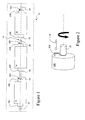
- Figure 1 depicts a turbomachinery train in accordance with an illustrative embodiment
- Figure 2 depicts an isometric diagram showing a sensor on a bearing housing for measuring axial vibrations in accordance with an illustrative embodiment
- Figure 3 depicts a computer system for processing axial vibration data in accordance with an illustrative embodiment.
- turbomachinery train 10 that includes three components 12, 14 and 16, each having a respective rotating shaft 24, 26, 28 serially connected to an adjacent component.
- Components 12, 14 and 16 may comprise any type of machinery having rotating shafts serially coupled.
- turbomachinery train 10 may include a turbogenerator in which component 12 is a high pressure turbine, component 14 is a low pressure turbine and component 16 is a generator.
- the components may include a clutch and/or any other device with a rotating shaft.
- turbomachinery train 10 may comprise any number or type of components, i.e., two or more, in which there is at least two shafts coupled together.
- each component 12, 14 and 16 may include a bearing housing 18A/18B, 20A/20B and 22A/22B, respectively.
- Bearing housings comprise bearings that hold the component's shaft in place and allow for the constrained relative rotational motion of the shaft with respect to the component.
- shaft 28 is misaligned with respect to shaft 26 at coupling N between bearing housings 20B and 22A.
- misalignment can cause damage to the associated bearings and/or rotors.
- the defect can be particularly problematic in the case where one of the affected components is a clutch, which allows the coupling between shafts to be disengaged, and which tends to be highly sensitive to misalignment problems.
- the components 12, 14 and 16 are typically encased in a sealed unit (e.g., as shown by the dotted line), and the cost for correcting such defects are high, properly identifying shaft misalignments can provide a significant enhancement in any condition monitoring process.
- axial vibration sensors 30A, 30B and 30C are attached to a surface of at least one bearing housing 18B, 20B and 22B.
- one axial vibration sensor is located at each interface in which shafts of adjacent components are coupled. Note that any number or placement of sensors could be utilized, e.g., to provide redundancy. As detailed below, by analyzing axial vibrations of the bearing housing proximate the shaft, misalignment between two coupled shafts can be evaluated.
- Figure 2 depicts a close up view of bearing housing 20B, shaft 26 and axial vibration sensor 30.
- axial vibration sensor 30B collects vibration data along the axial direction of the shaft 26, as shown by arrow 32. It is appreciated that the location, number and type of axial vibration sensors may vary depending on the particular implementation.
- axial vibration sensor 30B utilizes a piezoelectric probe that is permanently mounted or affixed onto the housing 20B to receive a continuous flow of axial vibration data.
- the axial vibration sensor 30B could be located somewhere other than housing 20B, e.g., on the foundation, integrated with a part of the component, etc.
- FIG 3 depicts a computer system 40 having a monitoring system 48 for processing axial vibration sensor data 50 and outputting alignment information 56.
- Axial vibration sensor data 50 may be collected from axial vibration sensors 30A, 30B and 30C ( Figures 1-2 ) in any manner, e.g., wired or wirelessly, analog or digital, etc.
- Monitoring system 48 which receives the axial vibration sensor data 50 as continuous or periodic time domain data, generally includes: (1) a frequency analyzer 52 that converts the time domain axial vibration sensor data into frequency domain data; and (2) an alignment analysis system 54 that analyzes the frequency domain data to provide alignment information 56.
- Frequency analyzer may utilize any technique to obtain frequency domain data, e.g., a Fourier transform, a fast Fourier transform (FFT), a spectral analysis such as a Cepstrum analysis, a Z transform, etc.
- Box 60 depicts an illustrative frequency analysis for coupling N ( Figure 1 , shafts 26 and 28) in which the magnitudes of different frequency components are graphed out.
- the frequency component at one times (1x) the running frequency of the shaft is evaluated (shown here with the arrow) by alignment analysis system 54. Misalignments are identified if the frequency component at 1x the running frequency of the shaft contains the dominant vibration amplitude peak, which is the case in the example shown for coupling N.
- alignment analysis system 54 may perform ancillary functions such as generating warnings, performing trend analysis to, e.g., predict future misalignments, providing maintenance scheduling for misaligned shafts, providing continuous real-time analysis, etc.
- computer system 40 may be implemented using any type of computing device.
- a computing device generally includes a processor 42, input/output (I/O 44), memory 46, and bus.
- the processor 42 may comprise a single processing unit, or be distributed across one or more processing units in one or more locations, e.g., on a client and server.
- Memory 46 may comprise any known type of data storage, including magnetic media, optical media, random access memory (RAM), read-only memory (ROM), a data cache, a data object, etc.
- RAM random access memory
- ROM read-only memory
- memory may reside at a single physical location, comprising one or more types of data storage, or be distributed across a plurality of physical systems in various forms.
- I/O 44 may comprise any system for exchanging information to/from an external resource.
- External devices/resources may comprise any known type of external device, including sensors, a monitor/display, speakers, storage, another computer system, a hand-held device, keyboard, mouse, voice recognition system, speech output system, printer, facsimile, pager, etc.
- the bus provides a communication link between each of the components in the computing device and likewise may comprise any known type of transmission link, including electrical, optical, wireless, etc.
- additional components such as cache memory, communication systems, system software, etc., may be incorporated.
- Access may be provided over a network such as the Internet, a local area network (LAN), a wide area network (WAN), a virtual private network (VPN), etc. Communication could occur via a direct hardwired connection (e.g., serial port), or via an addressable connection that may utilize any combination of wireline and/or wireless transmission methods. Moreover, conventional network connectivity, such as Token Ring, Ethernet, WiFi or other conventional communications standards could be used. Still yet, connectivity could be provided by conventional TCP/IP sockets-based protocol.
- LAN local area network
- WAN wide area network
- VPN virtual private network
- the features may be provided as one or more program products stored on a computer-readable storage medium, which when run, enables a computer system 40 to generate alignment information.
- the computer-readable storage medium may include program code, which implements the processes and systems described herein.
- the term "computer-readable storage medium" comprises one or more of any type of physical embodiment of the program code.
- the computer-readable storage medium can comprise program code embodied on one or more portable storage articles of manufacture (e.g., a compact disc, a magnetic disk, a tape, etc.), on one or more data storage portions of a computing device, such as memory and/or a storage system.
- program code and "computer program code” are synonymous and mean any expression, in any language, code or notation, of a set of instructions that cause a computing device having an information processing capability to perform a particular function either directly or after any combination of the following: (a) conversion to another language, code or notation; (b) reproduction in a different material form; and/or (c) decompression.
- program code can be embodied as one or more types of program products, such as an application/software program, component software/a library of functions, an operating system, a basic I/O system/driver for a particular computing and/or I/O device, and the like.
- terms such as “component”, “subsystem” and “system” are synonymous as used herein and represent any combination of hardware and/or software capable of performing some function(s).
- each block in the block diagrams may represent a module, segment, or portion of code, which comprises one or more executable instructions for implementing the specified logical function(s).
- the functions noted in the blocks may occur out of the order noted in the figures. For example, two blocks shown in succession may, in fact, be run substantially concurrently, or the blocks may sometimes be run in the reverse order, depending upon the functionality involved.
- each block of the block diagrams can be implemented by special purpose hardware-based systems which perform the specified functions or acts, or combinations of special purpose hardware and computer instructions.
Landscapes
- Physics & Mathematics (AREA)
- General Physics & Mathematics (AREA)
- Testing Of Devices, Machine Parts, Or Other Structures Thereof (AREA)
- Measurement Of Mechanical Vibrations Or Ultrasonic Waves (AREA)
Abstract
Description
- The subject matter disclosed herein relates to the art of measuring and monitoring axial vibrations to identify misalignments in turbomachinery trains.
- Turbomachinery trains comprise a set of components having serially coupled rotating shafts. A common example is a turbogenerator, which in its simplest form includes a turbine having a rotating shaft (i.e., a rotor) directly connected to a rotating shaft of an electric generator for the generation of electric power. More complex turbogenerator trains, such as those utilized in the power generation field, often comprise several large components having rotating shafts coupled in series. For example, a typical configuration may include a high pressure turbine having a rotating shaft that is coupled to a rotating shaft of a low pressure turbine, which is in turn coupled to a rotating shaft of a generator.
- When implementing such a train, it is imperative that the rotating shafts from each component behave in a precise manner in order to avoid damage the rotors or bearings. For instance, one common problem in such a configuration involves an unbalanced shaft, in which one of the shafts "wobbles." This defect is commonly detected by measuring radial (i.e., outwardly directed) vibrations using e.g., piezoelectric probes. However, such vibrations may also result from misaligned shafts, which can also cause damage to the rotors or bearing.
- The disclosed embodiments describe solutions for identifying misaligned shafts coupled within a turbomachinery train.
- A first aspect of the disclosure provides a system for determining a shaft misalignment in a train of components with serially coupled rotating shafts, comprising: a sensor affixed to a component of the train proximate a rotating shaft, wherein the sensor collects vibration data along an axial direction of the rotating shaft; a frequency analyzer for generating frequency domain data from the vibration data; and an analysis system for analyzing a frequency component of the frequency domain data at one times a rotational frequency of the rotating shaft to identify a misalignment between the rotating shaft and an adjacently coupled rotating shaft.
- A second aspect of the disclosure provides a train, comprising: a plurality of components with serially coupled rotating shafts; a sensor affixed to at least one component proximate a rotating shaft, wherein the sensor collects vibration data along an axial direction of the rotating shaft; a frequency analyzer for generating frequency domain data from the vibration data; and an analysis system for analyzing a frequency component of the frequency domain data at one times a rotational frequency of the rotating shaft to identify a misalignment between the rotating shaft and an adjacently coupled rotating shaft.
- A third aspect of the disclosure provides apparatus for determining a shaft misalignment in a train of components with serially coupled rotating shafts, comprising: a sensor affixed to a component of the train proximate a rotating shaft, wherein the sensor collects vibration data along an axial direction of the rotating shaft; a frequency analyzer for generating frequency domain data from the vibration data; and an analysis system for analyzing the frequency domain data to generate alignment information of the rotating shaft with respect to an adjacently coupled rotating shaft.
- The illustrative aspects of the present disclosure are designed to solve the problems herein described and/or other problems not discussed.
- These and other features of this disclosure will be more readily understood from the following detailed description of the various aspects of the disclosure taken in conjunction with the accompanying drawings that depict various embodiments of the disclosure, in which:
-
Figure 1 depicts a turbomachinery train in accordance with an illustrative embodiment; -
Figure 2 depicts an isometric diagram showing a sensor on a bearing housing for measuring axial vibrations in accordance with an illustrative embodiment; and -
Figure 3 depicts a computer system for processing axial vibration data in accordance with an illustrative embodiment. - It is noted that the drawings of the disclosure are not to scale. The drawings are intended to depict only typical aspects of the disclosure, and therefore should not be considered as limiting the scope of the disclosure. In the drawings, like numbering represents like elements between the drawings.
- The disclosed embodiments describe solutions for identifying misaligned shafts coupled within a turbomachinery train. Referring to the drawings,
Figure 1 shows aturbomachinery train 10 that includes threecomponents rotating shaft Components turbomachinery train 10 may include a turbogenerator in whichcomponent 12 is a high pressure turbine,component 14 is a low pressure turbine andcomponent 16 is a generator. In another embodiment, the components may include a clutch and/or any other device with a rotating shaft. In addition, it is understood thatturbomachinery train 10 may comprise any number or type of components, i.e., two or more, in which there is at least two shafts coupled together. - In addition to having a rotating shaft, each
component housing 18A/18B, 20A/20B and 22A/22B, respectively. Bearing housings comprise bearings that hold the component's shaft in place and allow for the constrained relative rotational motion of the shaft with respect to the component. - In the example shown in
Figure 1 it can be seen thatshaft 28 is misaligned with respect toshaft 26 at coupling N between bearinghousings components - To address this need,
axial vibration sensors housing -
Figure 2 depicts a close up view of bearinghousing 20B,shaft 26 and axial vibration sensor 30. As can be seen,axial vibration sensor 30B collects vibration data along the axial direction of theshaft 26, as shown byarrow 32. It is appreciated that the location, number and type of axial vibration sensors may vary depending on the particular implementation. In one illustrative embodiment,axial vibration sensor 30B utilizes a piezoelectric probe that is permanently mounted or affixed onto thehousing 20B to receive a continuous flow of axial vibration data. In another embodiment, theaxial vibration sensor 30B could be located somewhere other thanhousing 20B, e.g., on the foundation, integrated with a part of the component, etc. -
Figure 3 depicts acomputer system 40 having amonitoring system 48 for processing axialvibration sensor data 50 andoutputting alignment information 56. Axialvibration sensor data 50 may be collected fromaxial vibration sensors Figures 1-2 ) in any manner, e.g., wired or wirelessly, analog or digital, etc.Monitoring system 48, which receives the axialvibration sensor data 50 as continuous or periodic time domain data, generally includes: (1) afrequency analyzer 52 that converts the time domain axial vibration sensor data into frequency domain data; and (2) analignment analysis system 54 that analyzes the frequency domain data to providealignment information 56. - Frequency analyzer may utilize any technique to obtain frequency domain data, e.g., a Fourier transform, a fast Fourier transform (FFT), a spectral analysis such as a Cepstrum analysis, a Z transform, etc.
Box 60 depicts an illustrative frequency analysis for coupling N (Figure 1 ,shafts 26 and 28) in which the magnitudes of different frequency components are graphed out. In order to identify misalignments, the frequency component at one times (1x) the running frequency of the shaft is evaluated (shown here with the arrow) byalignment analysis system 54. Misalignments are identified if the frequency component at 1x the running frequency of the shaft contains the dominant vibration amplitude peak, which is the case in the example shown for coupling N. - In addition to identifying misalignments,
alignment analysis system 54 may perform ancillary functions such as generating warnings, performing trend analysis to, e.g., predict future misalignments, providing maintenance scheduling for misaligned shafts, providing continuous real-time analysis, etc. - It is understood that
computer system 40 may be implemented using any type of computing device. Such a computing device generally includes aprocessor 42, input/output (I/O 44),memory 46, and bus. Theprocessor 42 may comprise a single processing unit, or be distributed across one or more processing units in one or more locations, e.g., on a client and server.Memory 46 may comprise any known type of data storage, including magnetic media, optical media, random access memory (RAM), read-only memory (ROM), a data cache, a data object, etc. Moreover, memory may reside at a single physical location, comprising one or more types of data storage, or be distributed across a plurality of physical systems in various forms. - I/
O 44 may comprise any system for exchanging information to/from an external resource. External devices/resources may comprise any known type of external device, including sensors, a monitor/display, speakers, storage, another computer system, a hand-held device, keyboard, mouse, voice recognition system, speech output system, printer, facsimile, pager, etc. The bus provides a communication link between each of the components in the computing device and likewise may comprise any known type of transmission link, including electrical, optical, wireless, etc. Although not shown, additional components, such as cache memory, communication systems, system software, etc., may be incorporated. - Access may be provided over a network such as the Internet, a local area network (LAN), a wide area network (WAN), a virtual private network (VPN), etc. Communication could occur via a direct hardwired connection (e.g., serial port), or via an addressable connection that may utilize any combination of wireline and/or wireless transmission methods. Moreover, conventional network connectivity, such as Token Ring, Ethernet, WiFi or other conventional communications standards could be used. Still yet, connectivity could be provided by conventional TCP/IP sockets-based protocol.
- It is understood that in addition to being implemented as a system and method, the features may be provided as one or more program products stored on a computer-readable storage medium, which when run, enables a
computer system 40 to generate alignment information. To this extent, the computer-readable storage medium may include program code, which implements the processes and systems described herein. It is understood that the term "computer-readable storage medium" comprises one or more of any type of physical embodiment of the program code. In particular, the computer-readable storage medium can comprise program code embodied on one or more portable storage articles of manufacture (e.g., a compact disc, a magnetic disk, a tape, etc.), on one or more data storage portions of a computing device, such as memory and/or a storage system. - As used herein, it is understood that the terms "program code" and "computer program code" are synonymous and mean any expression, in any language, code or notation, of a set of instructions that cause a computing device having an information processing capability to perform a particular function either directly or after any combination of the following: (a) conversion to another language, code or notation; (b) reproduction in a different material form; and/or (c) decompression. To this extent, program code can be embodied as one or more types of program products, such as an application/software program, component software/a library of functions, an operating system, a basic I/O system/driver for a particular computing and/or I/O device, and the like. Further, it is understood that terms such as "component", "subsystem" and "system" are synonymous as used herein and represent any combination of hardware and/or software capable of performing some function(s).
- The block diagrams in the figures illustrate the architecture, functionality, and operation of possible implementations of systems, methods and computer program products according to various embodiments of the present invention. In this regard, each block in the block diagrams may represent a module, segment, or portion of code, which comprises one or more executable instructions for implementing the specified logical function(s). It should also be noted that the functions noted in the blocks may occur out of the order noted in the figures. For example, two blocks shown in succession may, in fact, be run substantially concurrently, or the blocks may sometimes be run in the reverse order, depending upon the functionality involved. It will also be noted that each block of the block diagrams can be implemented by special purpose hardware-based systems which perform the specified functions or acts, or combinations of special purpose hardware and computer instructions.
- The terminology used herein is for the purpose of describing particular embodiments only and is not intended to be limiting of the disclosure. As used herein, the singular forms "a", "an" and "the" are intended to include the plural forms as well, unless the context clearly indicates otherwise. It will be further understood that the terms "comprises" and/or "comprising," when used in this specification, specify the presence of stated features, integers, steps, operations, elements, and/or components, but do not preclude the presence or addition of one or more other features, integers, steps, operations, elements, components, and/or groups thereof.
- The corresponding structures, materials, acts, and equivalents of all means or step plus function elements in the claims below are intended to include any structure, material, or act for performing the function in combination with other claimed elements as specifically claimed. The description of the present disclosure has been presented for purposes of illustration and description, but is not intended to be exhaustive or limited to the disclosure in the form disclosed. Many modifications and variations will be apparent to those of ordinary skill in the art without departing from the scope and spirit of the disclosure. The embodiment was chosen and described in order to best explain the principles of the disclosure and the practical application, and to enable others of ordinary skill in the art to understand the disclosure for various embodiments with various modifications as are suited to the particular use contemplated.
Various aspects and embodiments of the present invention are defined by the following numbered clauses: - 1. A system for determining a shaft misalignment in a train of components with serially coupled rotating shafts, comprising:
- a sensor affixed to a component of the train proximate a rotating shaft, wherein the sensor collects vibration data along an axial direction of the rotating shaft;
- a frequency analyzer for generating frequency domain data from the vibration data; and
- an analysis system for analyzing a frequency component of the frequency domain data at one times a rotational frequency of the rotating shaft to identify a misalignment between the rotating shaft and an adjacently coupled rotating shaft.
- 2. The system of clause 1, wherein the sensor is affixed to a bearing housing proximate the rotating shaft.
- 3. The system of clause 1, wherein a peak magnitude at about one times the rotational frequency of the rotating shaft indicates a misalignment.
- 4. The system of clause 1, wherein the component comprises a clutch that allows the rotating shaft to be disengaged from the adjacently coupled rotating shaft.
- 5. The system of clause 1, wherein the analysis system evaluates trends in the frequency domain data to predict a possible misalignment.
- 6. The system of clause 1, wherein the analysis system outputs alignment information in a continuous manner.
- 7. The system of clause 1, wherein the analysis system outputs a warning if a misalignment is detected.
- 8. The system of clause 1, wherein the frequency analyzer utilizes a calculation selected from a group consisting of: a Fourier transform, a fast Fourier transform, a Cepstrum analysis, and a Z transform.
- 9. The system of clause 1, further comprising a plurality of sensors for collecting axial vibration data from a plurality of locations in the train.
- 10. A train, comprising:
- a plurality of components with serially coupled rotating shafts;
- a sensor affixed to at least one component proximate a rotating shaft, wherein the sensor collects vibration data along an axial direction of the rotating shaft;
- a frequency analyzer for generating frequency domain data from the vibration data; and
- an analysis system for analyzing a frequency component of the frequency domain data at one times a rotational frequency of the rotating shaft to identify a misalignment between the rotating shaft and an adjacently coupled rotating shaft.
- 11. The train of
clause 10, wherein the sensor is affixed to a bearing housing proximate the rotating shaft. - 12. The train of
clause 10, wherein a peak magnitude at about one times the rotational frequency of the rotating shaft indicates a misalignment. - 13. The train of
clause 10, wherein the at least one component comprises a clutch that allows the rotating shaft to be disengaged from the adjacently coupled rotating shaft. - 14. The train of
clause 10, wherein the analysis system evaluates trends in the frequency domain data to predict a future misalignment. - 15. The train of
clause 10, wherein the analysis system outputs alignment information in a continuous manner. - 16. The train of
clause 10, wherein the analysis system outputs a warning if a misalignment is detected. - 17. The train of
clause 10, wherein the frequency analyzer utilizes a calculation selected from a group consisting of: a Fourier transform, a fast Fourier transform, a Cepstrum analysis, and a Z transform. - 18. The train of
clause 10, further comprising a plurality of sensors for collecting axial vibration data from a plurality of locations in the train. - 19. An apparatus for determining a shaft misalignment in a train of components with serially coupled rotating shafts, comprising:
- a sensor affixed to a component of the train proximate a rotating shaft, wherein the sensor collects vibration data along an axial direction of the rotating shaft;
- a frequency analyzer for generating frequency domain data from the vibration data; and
- an analysis system for analyzing the frequency domain data to generate alignment information of the rotating shaft with respect to an adjacently coupled rotating shaft.
- 20. The apparatus of clause 19, wherein the sensor is affixed to a bearing housing proximate the rotating shaft.
Claims (9)
- A system for determining a shaft misalignment in a train of components (12, 14, 16) with serially coupled rotating shafts (24, 26, 28), comprising:a sensor (30A, 30B, and 30C) affixed to a component (12, 14, 16) of the train proximate a rotating shaft (24, 26, 28), wherein the sensor (30A, 30B, and 30C) collects vibration data along an axial direction (32) of the rotating shaft (24, 26, 28);a frequency analyzer (52) for generating frequency domain data from the vibration data; andan analysis system (54) for analyzing a frequency component (12, 14, 16) of the frequency domain data at one times a rotational frequency of the rotating shaft (24, 26, 28) to identify a misalignment between the rotating shaft (24, 26, 28) and an adjacently coupled rotating shaft (24, 26, 28).
- The system of claim 1, wherein the sensor (30A, 30B, and 30C) is affixed to a bearing housing (18A/18B, 20A/20B, 22A/22B) proximate the rotating shaft (24, 26, 28).
- The system of claim 1, wherein a peak magnitude at about one times the rotational frequency of the rotating shaft (24, 26, 28) indicates a misalignment.
- The system of claim 1, wherein the component (12, 14, 16) comprises a clutch that allows the rotating shaft (24, 26, 28) to be disengaged from the adjacently coupled rotating shaft (24, 26, 28).
- The system of claim 1, wherein the analysis system (54) evaluates trends in the frequency domain data to predict a possible misalignment.
- The system of claim 1, wherein the analysis system (54) outputs alignment information (56) in a continuous manner.
- The system of claim 1, wherein the analysis system (54) outputs a warning if a misalignment is detected.
- The system of claim 1, wherein the frequency analyzer (52) utilizes a calculation selected from a group consisting of: a Fourier transform, a fast Fourier transform, a Cepstrum analysis, and a Z transform.
- The system of claim 1, further comprising a plurality of sensors (30A, 30B, and 30C) for collecting axial vibration data (50) from a plurality of locations in the train.
Applications Claiming Priority (1)
| Application Number | Priority Date | Filing Date | Title |
|---|---|---|---|
| US12/765,974 US8322223B2 (en) | 2010-04-23 | 2010-04-23 | Axial vibration monitoring for detecting shaft misalignments in turbomachinary trains |
Publications (2)
| Publication Number | Publication Date |
|---|---|
| EP2381219A1 true EP2381219A1 (en) | 2011-10-26 |
| EP2381219B1 EP2381219B1 (en) | 2020-10-07 |
Family
ID=44259676
Family Applications (1)
| Application Number | Title | Priority Date | Filing Date |
|---|---|---|---|
| EP11163290.7A Not-in-force EP2381219B1 (en) | 2010-04-23 | 2011-04-20 | Axial vibration monitoring for detecting shaft misalignments in turbomachinery trains |
Country Status (4)
| Country | Link |
|---|---|
| US (1) | US8322223B2 (en) |
| EP (1) | EP2381219B1 (en) |
| JP (1) | JP5749964B2 (en) |
| RU (1) | RU2551388C2 (en) |
Cited By (3)
| Publication number | Priority date | Publication date | Assignee | Title |
|---|---|---|---|---|
| CN106679977A (en) * | 2017-01-03 | 2017-05-17 | 国电联合动力技术有限公司 | Wind turbine generator variable pitch bearing monitoring method and apparatus |
| CN113252347A (en) * | 2021-06-25 | 2021-08-13 | 深圳沈鼓测控技术有限公司 | Method and system for detecting misalignment fault of rotating mechanical shaft system |
| CN116026606A (en) * | 2022-12-13 | 2023-04-28 | 深圳技术大学 | Method and apparatus for detecting compound vibration of a vehicle driveline |
Families Citing this family (8)
| Publication number | Priority date | Publication date | Assignee | Title |
|---|---|---|---|---|
| NL2006686C2 (en) * | 2011-04-29 | 2012-10-30 | Micro Turbine Technology B V | An integral method for vibration compensation and misalignment prevention in rotor dynamic systems. |
| CN103335838B (en) * | 2013-06-06 | 2015-08-19 | 大连理工大学 | Misalign spline vibration abrasion contrast experiment device |
| DE102015207134A1 (en) * | 2015-04-20 | 2016-10-20 | Prüftechnik Dieter Busch AG | Method for detecting vibrations of a device and vibration detection system |
| DE102018108827B3 (en) * | 2018-04-13 | 2019-05-29 | Trumpf Schweiz Ag | Method for controlling at least one radial fan in a refrigeration system and radial fan |
| CN112945550B (en) * | 2019-12-11 | 2022-06-07 | 中车株洲电力机车研究所有限公司 | High-speed shaft centering realization method under dynamic working condition of wind turbine generator |
| AT524535B1 (en) * | 2021-01-15 | 2022-07-15 | Avl List Gmbh | Method for correcting a misalignment of at least one shafting |
| EP4083571A1 (en) * | 2021-04-26 | 2022-11-02 | Siemens Aktiengesellschaft | Method and device for detecting and signalling misalignment between a first shaft and a second shaft |
| JP7830291B2 (en) * | 2022-11-02 | 2026-03-16 | 株式会社東芝 | Vibration-reducing clutch coupling control method and vibration-reducing clutch coupling control device |
Citations (6)
| Publication number | Priority date | Publication date | Assignee | Title |
|---|---|---|---|---|
| US5194920A (en) * | 1989-06-26 | 1993-03-16 | Imatran Voima Oy | Method and apparatus for measuring alignment status |
| US5365787A (en) * | 1991-10-02 | 1994-11-22 | Monitoring Technology Corp. | Noninvasive method and apparatus for determining resonance information for rotating machinery components and for anticipating component failure from changes therein |
| US6768938B2 (en) * | 2001-11-16 | 2004-07-27 | Goodrich Pump & Engine Control Systems, Inc. | Vibration monitoring system for gas turbine engines |
| US20050065712A1 (en) * | 2003-09-19 | 2005-03-24 | Skilton Timothy L. | Engine balancing system and method |
| US20090055129A1 (en) * | 2002-04-23 | 2009-02-26 | Altieri Russell E | Aircraft vehicular propulsion system monitoring device and method |
| US20090263247A1 (en) * | 2008-04-21 | 2009-10-22 | Daniel Edward Mollmann | Dual rotor vibration monitoring |
Family Cites Families (12)
| Publication number | Priority date | Publication date | Assignee | Title |
|---|---|---|---|---|
| JPS56130634A (en) * | 1980-03-19 | 1981-10-13 | Hitachi Ltd | Method and device for monitoring oscillation of rotary machine |
| JPS5981532A (en) * | 1982-11-02 | 1984-05-11 | Hitachi Ltd | Abnormality diagnosis device for diaphragm coupling in shaft system |
| JPS62833A (en) * | 1985-06-26 | 1987-01-06 | Toshiba Corp | Abnormality diagnosing device for rotary machine |
| JPS63150633A (en) * | 1986-12-16 | 1988-06-23 | Toshiba Corp | Shaft vibration diagnosing device |
| FI83565C (en) * | 1989-06-26 | 1991-07-25 | Imatran Voima Oy | Method and apparatus for measuring alignment state |
| US5544073A (en) * | 1994-06-02 | 1996-08-06 | Computational Systems, Inc. | Rotor balancing calculator |
| US6092029A (en) | 1998-02-19 | 2000-07-18 | Bently Nevada Corporation | Method and apparatus for diagnosing and controlling rotating stall and surge in rotating machinery |
| US6289735B1 (en) * | 1998-09-29 | 2001-09-18 | Reliance Electric Technologies, Llc | Machine diagnostic system and method for vibration analysis |
| US7133801B2 (en) * | 2002-06-07 | 2006-11-07 | Exxon Mobil Research And Engineering Company | System and methodology for vibration analysis and condition monitoring |
| CN1878038A (en) * | 2005-06-07 | 2006-12-13 | 洛克威尔自动控制技术股份有限公司 | Wireless modular monitoring and protection system topology |
| JP5185677B2 (en) * | 2008-03-31 | 2013-04-17 | 三菱重工業株式会社 | Axial displacement detection method in driving force transmission mechanism using self-aligning engagement clutch |
| TWI474023B (en) * | 2008-12-10 | 2015-02-21 | Ind Tech Res Inst | Diagnosis method for diagnosing fault in operation of a motor fault and diagnosis device using the same |
-
2010
- 2010-04-23 US US12/765,974 patent/US8322223B2/en not_active Expired - Fee Related
-
2011
- 2011-04-15 JP JP2011090648A patent/JP5749964B2/en not_active Expired - Fee Related
- 2011-04-20 EP EP11163290.7A patent/EP2381219B1/en not_active Not-in-force
- 2011-04-21 RU RU2011115527/28A patent/RU2551388C2/en active
Patent Citations (6)
| Publication number | Priority date | Publication date | Assignee | Title |
|---|---|---|---|---|
| US5194920A (en) * | 1989-06-26 | 1993-03-16 | Imatran Voima Oy | Method and apparatus for measuring alignment status |
| US5365787A (en) * | 1991-10-02 | 1994-11-22 | Monitoring Technology Corp. | Noninvasive method and apparatus for determining resonance information for rotating machinery components and for anticipating component failure from changes therein |
| US6768938B2 (en) * | 2001-11-16 | 2004-07-27 | Goodrich Pump & Engine Control Systems, Inc. | Vibration monitoring system for gas turbine engines |
| US20090055129A1 (en) * | 2002-04-23 | 2009-02-26 | Altieri Russell E | Aircraft vehicular propulsion system monitoring device and method |
| US20050065712A1 (en) * | 2003-09-19 | 2005-03-24 | Skilton Timothy L. | Engine balancing system and method |
| US20090263247A1 (en) * | 2008-04-21 | 2009-10-22 | Daniel Edward Mollmann | Dual rotor vibration monitoring |
Cited By (5)
| Publication number | Priority date | Publication date | Assignee | Title |
|---|---|---|---|---|
| CN106679977A (en) * | 2017-01-03 | 2017-05-17 | 国电联合动力技术有限公司 | Wind turbine generator variable pitch bearing monitoring method and apparatus |
| CN113252347A (en) * | 2021-06-25 | 2021-08-13 | 深圳沈鼓测控技术有限公司 | Method and system for detecting misalignment fault of rotating mechanical shaft system |
| CN113252347B (en) * | 2021-06-25 | 2021-10-01 | 深圳沈鼓测控技术有限公司 | Method and system for detecting misalignment fault of rotating mechanical shaft system |
| CN116026606A (en) * | 2022-12-13 | 2023-04-28 | 深圳技术大学 | Method and apparatus for detecting compound vibration of a vehicle driveline |
| CN116026606B (en) * | 2022-12-13 | 2023-08-25 | 深圳技术大学 | Method and apparatus for detecting compound vibration of a vehicle driveline |
Also Published As
| Publication number | Publication date |
|---|---|
| RU2551388C2 (en) | 2015-05-20 |
| US20110259103A1 (en) | 2011-10-27 |
| JP5749964B2 (en) | 2015-07-15 |
| JP2011232334A (en) | 2011-11-17 |
| US8322223B2 (en) | 2012-12-04 |
| EP2381219B1 (en) | 2020-10-07 |
| RU2011115527A (en) | 2012-10-27 |
Similar Documents
| Publication | Publication Date | Title |
|---|---|---|
| EP2381219B1 (en) | Axial vibration monitoring for detecting shaft misalignments in turbomachinery trains | |
| Saruhan et al. | Vibration analysis of rolling element bearings defects | |
| Bechhoefer et al. | Processing for improved spectral analysis | |
| Saucedo-Dorantes et al. | Multiple‐Fault Detection Methodology Based on Vibration and Current Analysis Applied to Bearings in Induction Motors and Gearboxes on the Kinematic Chain | |
| García Márquez et al. | Acoustic inspection system with unmanned aerial vehicles for wind turbines structure health monitoring | |
| JP6196093B2 (en) | Vibration analysis method for bearing device, vibration analysis device for bearing device, and state monitoring device for rolling bearing | |
| Feng et al. | Implementation of envelope analysis on a wireless condition monitoring system for bearing fault diagnosis | |
| JP5958932B2 (en) | Dynamic equipment condition monitoring system, method and program | |
| Teng et al. | Detection and quantization of bearing fault in direct drive wind turbine via comparative analysis | |
| Garg et al. | Current signature analysis and its application in the condition monitoring of wind turbine for rotor faults | |
| Li et al. | On-line fault detection in wind turbine transmission system using adaptive filter and robust statistical features | |
| Sawalhi et al. | Vibration signal processing using cepstrum editing technique to enhance spall-related vibration features in rolling element bearings | |
| Afshar et al. | Generalized roughness bearing fault diagnosis using time series analysis and gradient boosted tree | |
| Babu et al. | Review on various signal processing techniques for predictive maintenance | |
| JP7394031B2 (en) | Abnormality detection device and abnormality detection method for rolling bearings | |
| KR102886427B1 (en) | Vibration data security system of rotating equipment and security method the same | |
| Almutairi et al. | Standardisation of Vibration-based Parameters for Rotor and Bearing for Machine Faults Detection Using Machine Learning Model | |
| Muhammad et al. | Frequency spectrum-based diagnosis of structural gear faults using dual-sensor acoustic and vibration signals | |
| Pederiva | Application of wavelet transform to detect faults in rotating machinery | |
| JP6243940B2 (en) | Wind power generation system abnormality sign diagnosis system | |
| Pita et al. | Software development firmware system for broken rotor bar detection and diagnosis of induction motor through current signature analysis | |
| CN113994088A (en) | Method for computer-implemented monitoring of components of a wind turbine | |
| Mahto et al. | Investigation of unbalance fault using signature analysis and the taguchi method | |
| Kawada et al. | Visualization of contact vibration generated on turbine model using fast Haar wavelet transform | |
| Zhou et al. | A knowledge base system for rotary equipment fault detection and diagnosis |
Legal Events
| Date | Code | Title | Description |
|---|---|---|---|
| AK | Designated contracting states |
Kind code of ref document: A1 Designated state(s): AL AT BE BG CH CY CZ DE DK EE ES FI FR GB GR HR HU IE IS IT LI LT LU LV MC MK MT NL NO PL PT RO RS SE SI SK SM TR |
|
| AX | Request for extension of the european patent |
Extension state: BA ME |
|
| PUAI | Public reference made under article 153(3) epc to a published international application that has entered the european phase |
Free format text: ORIGINAL CODE: 0009012 |
|
| 17P | Request for examination filed |
Effective date: 20120426 |
|
| STAA | Information on the status of an ep patent application or granted ep patent |
Free format text: STATUS: EXAMINATION IS IN PROGRESS |
|
| 17Q | First examination report despatched |
Effective date: 20170421 |
|
| RIC1 | Information provided on ipc code assigned before grant |
Ipc: G01B 21/24 20060101AFI20200211BHEP Ipc: G01H 1/00 20060101ALN20200211BHEP |
|
| RIC1 | Information provided on ipc code assigned before grant |
Ipc: G01H 1/00 20060101ALN20200217BHEP Ipc: G01B 21/24 20060101AFI20200217BHEP |
|
| GRAP | Despatch of communication of intention to grant a patent |
Free format text: ORIGINAL CODE: EPIDOSNIGR1 |
|
| STAA | Information on the status of an ep patent application or granted ep patent |
Free format text: STATUS: GRANT OF PATENT IS INTENDED |
|
| INTG | Intention to grant announced |
Effective date: 20200508 |
|
| GRAS | Grant fee paid |
Free format text: ORIGINAL CODE: EPIDOSNIGR3 |
|
| GRAA | (expected) grant |
Free format text: ORIGINAL CODE: 0009210 |
|
| STAA | Information on the status of an ep patent application or granted ep patent |
Free format text: STATUS: THE PATENT HAS BEEN GRANTED |
|
| AK | Designated contracting states |
Kind code of ref document: B1 Designated state(s): AL AT BE BG CH CY CZ DE DK EE ES FI FR GB GR HR HU IE IS IT LI LT LU LV MC MK MT NL NO PL PT RO RS SE SI SK SM TR |
|
| REG | Reference to a national code |
Ref country code: GB Ref legal event code: FG4D |
|
| REG | Reference to a national code |
Ref country code: CH Ref legal event code: EP Ref country code: AT Ref legal event code: REF Ref document number: 1321629 Country of ref document: AT Kind code of ref document: T Effective date: 20201015 |
|
| REG | Reference to a national code |
Ref country code: DE Ref legal event code: R096 Ref document number: 602011068828 Country of ref document: DE |
|
| REG | Reference to a national code |
Ref country code: IE Ref legal event code: FG4D |
|
| REG | Reference to a national code |
Ref country code: NL Ref legal event code: MP Effective date: 20201007 |
|
| REG | Reference to a national code |
Ref country code: AT Ref legal event code: MK05 Ref document number: 1321629 Country of ref document: AT Kind code of ref document: T Effective date: 20201007 |
|
| PG25 | Lapsed in a contracting state [announced via postgrant information from national office to epo] |
Ref country code: GR Free format text: LAPSE BECAUSE OF FAILURE TO SUBMIT A TRANSLATION OF THE DESCRIPTION OR TO PAY THE FEE WITHIN THE PRESCRIBED TIME-LIMIT Effective date: 20210108 Ref country code: NO Free format text: LAPSE BECAUSE OF FAILURE TO SUBMIT A TRANSLATION OF THE DESCRIPTION OR TO PAY THE FEE WITHIN THE PRESCRIBED TIME-LIMIT Effective date: 20210107 Ref country code: NL Free format text: LAPSE BECAUSE OF FAILURE TO SUBMIT A TRANSLATION OF THE DESCRIPTION OR TO PAY THE FEE WITHIN THE PRESCRIBED TIME-LIMIT Effective date: 20201007 Ref country code: PT Free format text: LAPSE BECAUSE OF FAILURE TO SUBMIT A TRANSLATION OF THE DESCRIPTION OR TO PAY THE FEE WITHIN THE PRESCRIBED TIME-LIMIT Effective date: 20210208 Ref country code: RS Free format text: LAPSE BECAUSE OF FAILURE TO SUBMIT A TRANSLATION OF THE DESCRIPTION OR TO PAY THE FEE WITHIN THE PRESCRIBED TIME-LIMIT Effective date: 20201007 Ref country code: FI Free format text: LAPSE BECAUSE OF FAILURE TO SUBMIT A TRANSLATION OF THE DESCRIPTION OR TO PAY THE FEE WITHIN THE PRESCRIBED TIME-LIMIT Effective date: 20201007 |
|
| REG | Reference to a national code |
Ref country code: LT Ref legal event code: MG4D |
|
| PG25 | Lapsed in a contracting state [announced via postgrant information from national office to epo] |
Ref country code: PL Free format text: LAPSE BECAUSE OF FAILURE TO SUBMIT A TRANSLATION OF THE DESCRIPTION OR TO PAY THE FEE WITHIN THE PRESCRIBED TIME-LIMIT Effective date: 20201007 Ref country code: LV Free format text: LAPSE BECAUSE OF FAILURE TO SUBMIT A TRANSLATION OF THE DESCRIPTION OR TO PAY THE FEE WITHIN THE PRESCRIBED TIME-LIMIT Effective date: 20201007 Ref country code: SE Free format text: LAPSE BECAUSE OF FAILURE TO SUBMIT A TRANSLATION OF THE DESCRIPTION OR TO PAY THE FEE WITHIN THE PRESCRIBED TIME-LIMIT Effective date: 20201007 Ref country code: BG Free format text: LAPSE BECAUSE OF FAILURE TO SUBMIT A TRANSLATION OF THE DESCRIPTION OR TO PAY THE FEE WITHIN THE PRESCRIBED TIME-LIMIT Effective date: 20210107 Ref country code: AT Free format text: LAPSE BECAUSE OF FAILURE TO SUBMIT A TRANSLATION OF THE DESCRIPTION OR TO PAY THE FEE WITHIN THE PRESCRIBED TIME-LIMIT Effective date: 20201007 Ref country code: ES Free format text: LAPSE BECAUSE OF FAILURE TO SUBMIT A TRANSLATION OF THE DESCRIPTION OR TO PAY THE FEE WITHIN THE PRESCRIBED TIME-LIMIT Effective date: 20201007 Ref country code: IS Free format text: LAPSE BECAUSE OF FAILURE TO SUBMIT A TRANSLATION OF THE DESCRIPTION OR TO PAY THE FEE WITHIN THE PRESCRIBED TIME-LIMIT Effective date: 20210207 |
|
| PG25 | Lapsed in a contracting state [announced via postgrant information from national office to epo] |
Ref country code: HR Free format text: LAPSE BECAUSE OF FAILURE TO SUBMIT A TRANSLATION OF THE DESCRIPTION OR TO PAY THE FEE WITHIN THE PRESCRIBED TIME-LIMIT Effective date: 20201007 |
|
| REG | Reference to a national code |
Ref country code: DE Ref legal event code: R097 Ref document number: 602011068828 Country of ref document: DE |
|
| PG25 | Lapsed in a contracting state [announced via postgrant information from national office to epo] |
Ref country code: SK Free format text: LAPSE BECAUSE OF FAILURE TO SUBMIT A TRANSLATION OF THE DESCRIPTION OR TO PAY THE FEE WITHIN THE PRESCRIBED TIME-LIMIT Effective date: 20201007 Ref country code: RO Free format text: LAPSE BECAUSE OF FAILURE TO SUBMIT A TRANSLATION OF THE DESCRIPTION OR TO PAY THE FEE WITHIN THE PRESCRIBED TIME-LIMIT Effective date: 20201007 Ref country code: SM Free format text: LAPSE BECAUSE OF FAILURE TO SUBMIT A TRANSLATION OF THE DESCRIPTION OR TO PAY THE FEE WITHIN THE PRESCRIBED TIME-LIMIT Effective date: 20201007 Ref country code: CZ Free format text: LAPSE BECAUSE OF FAILURE TO SUBMIT A TRANSLATION OF THE DESCRIPTION OR TO PAY THE FEE WITHIN THE PRESCRIBED TIME-LIMIT Effective date: 20201007 Ref country code: EE Free format text: LAPSE BECAUSE OF FAILURE TO SUBMIT A TRANSLATION OF THE DESCRIPTION OR TO PAY THE FEE WITHIN THE PRESCRIBED TIME-LIMIT Effective date: 20201007 Ref country code: LT Free format text: LAPSE BECAUSE OF FAILURE TO SUBMIT A TRANSLATION OF THE DESCRIPTION OR TO PAY THE FEE WITHIN THE PRESCRIBED TIME-LIMIT Effective date: 20201007 |
|
| PLBE | No opposition filed within time limit |
Free format text: ORIGINAL CODE: 0009261 |
|
| STAA | Information on the status of an ep patent application or granted ep patent |
Free format text: STATUS: NO OPPOSITION FILED WITHIN TIME LIMIT |
|
| PG25 | Lapsed in a contracting state [announced via postgrant information from national office to epo] |
Ref country code: DK Free format text: LAPSE BECAUSE OF FAILURE TO SUBMIT A TRANSLATION OF THE DESCRIPTION OR TO PAY THE FEE WITHIN THE PRESCRIBED TIME-LIMIT Effective date: 20201007 |
|
| 26N | No opposition filed |
Effective date: 20210708 |
|
| PG25 | Lapsed in a contracting state [announced via postgrant information from national office to epo] |
Ref country code: AL Free format text: LAPSE BECAUSE OF FAILURE TO SUBMIT A TRANSLATION OF THE DESCRIPTION OR TO PAY THE FEE WITHIN THE PRESCRIBED TIME-LIMIT Effective date: 20201007 |
|
| REG | Reference to a national code |
Ref country code: DE Ref legal event code: R119 Ref document number: 602011068828 Country of ref document: DE |
|
| PG25 | Lapsed in a contracting state [announced via postgrant information from national office to epo] |
Ref country code: SI Free format text: LAPSE BECAUSE OF FAILURE TO SUBMIT A TRANSLATION OF THE DESCRIPTION OR TO PAY THE FEE WITHIN THE PRESCRIBED TIME-LIMIT Effective date: 20201007 Ref country code: MC Free format text: LAPSE BECAUSE OF FAILURE TO SUBMIT A TRANSLATION OF THE DESCRIPTION OR TO PAY THE FEE WITHIN THE PRESCRIBED TIME-LIMIT Effective date: 20201007 |
|
| GBPC | Gb: european patent ceased through non-payment of renewal fee |
Effective date: 20210420 |
|
| PG25 | Lapsed in a contracting state [announced via postgrant information from national office to epo] |
Ref country code: LU Free format text: LAPSE BECAUSE OF NON-PAYMENT OF DUE FEES Effective date: 20210420 |
|
| REG | Reference to a national code |
Ref country code: BE Ref legal event code: MM Effective date: 20210430 |
|
| PG25 | Lapsed in a contracting state [announced via postgrant information from national office to epo] |
Ref country code: LI Free format text: LAPSE BECAUSE OF NON-PAYMENT OF DUE FEES Effective date: 20210430 Ref country code: CH Free format text: LAPSE BECAUSE OF NON-PAYMENT OF DUE FEES Effective date: 20210430 Ref country code: DE Free format text: LAPSE BECAUSE OF NON-PAYMENT OF DUE FEES Effective date: 20211103 Ref country code: GB Free format text: LAPSE BECAUSE OF NON-PAYMENT OF DUE FEES Effective date: 20210420 Ref country code: FR Free format text: LAPSE BECAUSE OF NON-PAYMENT OF DUE FEES Effective date: 20210430 |
|
| PG25 | Lapsed in a contracting state [announced via postgrant information from national office to epo] |
Ref country code: IE Free format text: LAPSE BECAUSE OF NON-PAYMENT OF DUE FEES Effective date: 20210420 |
|
| PG25 | Lapsed in a contracting state [announced via postgrant information from national office to epo] |
Ref country code: IS Free format text: LAPSE BECAUSE OF FAILURE TO SUBMIT A TRANSLATION OF THE DESCRIPTION OR TO PAY THE FEE WITHIN THE PRESCRIBED TIME-LIMIT Effective date: 20210207 |
|
| PG25 | Lapsed in a contracting state [announced via postgrant information from national office to epo] |
Ref country code: BE Free format text: LAPSE BECAUSE OF NON-PAYMENT OF DUE FEES Effective date: 20210430 |
|
| PG25 | Lapsed in a contracting state [announced via postgrant information from national office to epo] |
Ref country code: IT Free format text: LAPSE BECAUSE OF NON-PAYMENT OF DUE FEES Effective date: 20210420 |
|
| PG25 | Lapsed in a contracting state [announced via postgrant information from national office to epo] |
Ref country code: HU Free format text: LAPSE BECAUSE OF FAILURE TO SUBMIT A TRANSLATION OF THE DESCRIPTION OR TO PAY THE FEE WITHIN THE PRESCRIBED TIME-LIMIT; INVALID AB INITIO Effective date: 20110420 Ref country code: CY Free format text: LAPSE BECAUSE OF FAILURE TO SUBMIT A TRANSLATION OF THE DESCRIPTION OR TO PAY THE FEE WITHIN THE PRESCRIBED TIME-LIMIT Effective date: 20201007 |
|
| PG25 | Lapsed in a contracting state [announced via postgrant information from national office to epo] |
Ref country code: MK Free format text: LAPSE BECAUSE OF FAILURE TO SUBMIT A TRANSLATION OF THE DESCRIPTION OR TO PAY THE FEE WITHIN THE PRESCRIBED TIME-LIMIT Effective date: 20201007 |
|
| PG25 | Lapsed in a contracting state [announced via postgrant information from national office to epo] |
Ref country code: MT Free format text: LAPSE BECAUSE OF FAILURE TO SUBMIT A TRANSLATION OF THE DESCRIPTION OR TO PAY THE FEE WITHIN THE PRESCRIBED TIME-LIMIT Effective date: 20201007 |
|
| PG25 | Lapsed in a contracting state [announced via postgrant information from national office to epo] |
Ref country code: TR Free format text: LAPSE BECAUSE OF FAILURE TO SUBMIT A TRANSLATION OF THE DESCRIPTION OR TO PAY THE FEE WITHIN THE PRESCRIBED TIME-LIMIT Effective date: 20201007 |