EP2381080A2 - Accessory gearbox with a starter/generator - Google Patents
Accessory gearbox with a starter/generator Download PDFInfo
- Publication number
- EP2381080A2 EP2381080A2 EP11162997A EP11162997A EP2381080A2 EP 2381080 A2 EP2381080 A2 EP 2381080A2 EP 11162997 A EP11162997 A EP 11162997A EP 11162997 A EP11162997 A EP 11162997A EP 2381080 A2 EP2381080 A2 EP 2381080A2
- Authority
- EP
- European Patent Office
- Prior art keywords
- shaft
- pmg
- assembly
- exciter
- generator
- Prior art date
- Legal status (The legal status is an assumption and is not a legal conclusion. Google has not performed a legal analysis and makes no representation as to the accuracy of the status listed.)
- Withdrawn
Links
- 239000007858 starting material Substances 0.000 title claims abstract description 22
- 239000007789 gas Substances 0.000 description 27
- 230000006835 compression Effects 0.000 description 7
- 238000007906 compression Methods 0.000 description 7
- 238000002485 combustion reaction Methods 0.000 description 4
- 239000000446 fuel Substances 0.000 description 3
- 230000008901 benefit Effects 0.000 description 2
- 230000008878 coupling Effects 0.000 description 2
- 238000010168 coupling process Methods 0.000 description 2
- 238000005859 coupling reaction Methods 0.000 description 2
- 229910000640 Fe alloy Inorganic materials 0.000 description 1
- 230000009286 beneficial effect Effects 0.000 description 1
- 230000005540 biological transmission Effects 0.000 description 1
- 238000001816 cooling Methods 0.000 description 1
- 239000012530 fluid Substances 0.000 description 1
- 230000006870 function Effects 0.000 description 1
- XWHPIFXRKKHEKR-UHFFFAOYSA-N iron silicon Chemical compound [Si].[Fe] XWHPIFXRKKHEKR-UHFFFAOYSA-N 0.000 description 1
- 230000033001 locomotion Effects 0.000 description 1
- 230000013011 mating Effects 0.000 description 1
- 230000005226 mechanical processes and functions Effects 0.000 description 1
- 238000000034 method Methods 0.000 description 1
- 238000010248 power generation Methods 0.000 description 1
- 239000007779 soft material Substances 0.000 description 1
- 230000001360 synchronised effect Effects 0.000 description 1
- 238000011144 upstream manufacturing Methods 0.000 description 1
- 238000004804 winding Methods 0.000 description 1
Images

Classifications
-
- F—MECHANICAL ENGINEERING; LIGHTING; HEATING; WEAPONS; BLASTING
- F02—COMBUSTION ENGINES; HOT-GAS OR COMBUSTION-PRODUCT ENGINE PLANTS
- F02C—GAS-TURBINE PLANTS; AIR INTAKES FOR JET-PROPULSION PLANTS; CONTROLLING FUEL SUPPLY IN AIR-BREATHING JET-PROPULSION PLANTS
- F02C7/00—Features, components parts, details or accessories, not provided for in, or of interest apart form groups F02C1/00 - F02C6/00; Air intakes for jet-propulsion plants
- F02C7/36—Power transmission arrangements between the different shafts of the gas turbine plant, or between the gas-turbine plant and the power user
-
- B—PERFORMING OPERATIONS; TRANSPORTING
- B64—AIRCRAFT; AVIATION; COSMONAUTICS
- B64D—EQUIPMENT FOR FITTING IN OR TO AIRCRAFT; FLIGHT SUITS; PARACHUTES; ARRANGEMENT OR MOUNTING OF POWER PLANTS OR PROPULSION TRANSMISSIONS IN AIRCRAFT
- B64D41/00—Power installations for auxiliary purposes
-
- F—MECHANICAL ENGINEERING; LIGHTING; HEATING; WEAPONS; BLASTING
- F02—COMBUSTION ENGINES; HOT-GAS OR COMBUSTION-PRODUCT ENGINE PLANTS
- F02C—GAS-TURBINE PLANTS; AIR INTAKES FOR JET-PROPULSION PLANTS; CONTROLLING FUEL SUPPLY IN AIR-BREATHING JET-PROPULSION PLANTS
- F02C7/00—Features, components parts, details or accessories, not provided for in, or of interest apart form groups F02C1/00 - F02C6/00; Air intakes for jet-propulsion plants
- F02C7/26—Starting; Ignition
- F02C7/268—Starting drives for the rotor, acting directly on the rotor of the gas turbine to be started
- F02C7/275—Mechanical drives
-
- F—MECHANICAL ENGINEERING; LIGHTING; HEATING; WEAPONS; BLASTING
- F02—COMBUSTION ENGINES; HOT-GAS OR COMBUSTION-PRODUCT ENGINE PLANTS
- F02C—GAS-TURBINE PLANTS; AIR INTAKES FOR JET-PROPULSION PLANTS; CONTROLLING FUEL SUPPLY IN AIR-BREATHING JET-PROPULSION PLANTS
- F02C7/00—Features, components parts, details or accessories, not provided for in, or of interest apart form groups F02C1/00 - F02C6/00; Air intakes for jet-propulsion plants
- F02C7/32—Arrangement, mounting, or driving, of auxiliaries
-
- H—ELECTRICITY
- H02—GENERATION; CONVERSION OR DISTRIBUTION OF ELECTRIC POWER
- H02K—DYNAMO-ELECTRIC MACHINES
- H02K19/00—Synchronous motors or generators
- H02K19/16—Synchronous generators
- H02K19/38—Structural association of synchronous generators with exciting machines
-
- H—ELECTRICITY
- H02—GENERATION; CONVERSION OR DISTRIBUTION OF ELECTRIC POWER
- H02K—DYNAMO-ELECTRIC MACHINES
- H02K7/00—Arrangements for handling mechanical energy structurally associated with dynamo-electric machines, e.g. structural association with mechanical driving motors or auxiliary dynamo-electric machines
- H02K7/10—Structural association with clutches, brakes, gears, pulleys or mechanical starters
- H02K7/116—Structural association with clutches, brakes, gears, pulleys or mechanical starters with gears
-
- F—MECHANICAL ENGINEERING; LIGHTING; HEATING; WEAPONS; BLASTING
- F05—INDEXING SCHEMES RELATING TO ENGINES OR PUMPS IN VARIOUS SUBCLASSES OF CLASSES F01-F04
- F05D—INDEXING SCHEME FOR ASPECTS RELATING TO NON-POSITIVE-DISPLACEMENT MACHINES OR ENGINES, GAS-TURBINES OR JET-PROPULSION PLANTS
- F05D2220/00—Application
- F05D2220/70—Application in combination with
- F05D2220/76—Application in combination with an electrical generator
- F05D2220/764—Application in combination with an electrical generator of the alternating current (A.C.) type
-
- F—MECHANICAL ENGINEERING; LIGHTING; HEATING; WEAPONS; BLASTING
- F05—INDEXING SCHEMES RELATING TO ENGINES OR PUMPS IN VARIOUS SUBCLASSES OF CLASSES F01-F04
- F05D—INDEXING SCHEME FOR ASPECTS RELATING TO NON-POSITIVE-DISPLACEMENT MACHINES OR ENGINES, GAS-TURBINES OR JET-PROPULSION PLANTS
- F05D2220/00—Application
- F05D2220/70—Application in combination with
- F05D2220/76—Application in combination with an electrical generator
- F05D2220/768—Application in combination with an electrical generator equipped with permanent magnets
-
- Y—GENERAL TAGGING OF NEW TECHNOLOGICAL DEVELOPMENTS; GENERAL TAGGING OF CROSS-SECTIONAL TECHNOLOGIES SPANNING OVER SEVERAL SECTIONS OF THE IPC; TECHNICAL SUBJECTS COVERED BY FORMER USPC CROSS-REFERENCE ART COLLECTIONS [XRACs] AND DIGESTS
- Y02—TECHNOLOGIES OR APPLICATIONS FOR MITIGATION OR ADAPTATION AGAINST CLIMATE CHANGE
- Y02T—CLIMATE CHANGE MITIGATION TECHNOLOGIES RELATED TO TRANSPORTATION
- Y02T50/00—Aeronautics or air transport
- Y02T50/40—Weight reduction
-
- Y—GENERAL TAGGING OF NEW TECHNOLOGICAL DEVELOPMENTS; GENERAL TAGGING OF CROSS-SECTIONAL TECHNOLOGIES SPANNING OVER SEVERAL SECTIONS OF THE IPC; TECHNICAL SUBJECTS COVERED BY FORMER USPC CROSS-REFERENCE ART COLLECTIONS [XRACs] AND DIGESTS
- Y02—TECHNOLOGIES OR APPLICATIONS FOR MITIGATION OR ADAPTATION AGAINST CLIMATE CHANGE
- Y02T—CLIMATE CHANGE MITIGATION TECHNOLOGIES RELATED TO TRANSPORTATION
- Y02T50/00—Aeronautics or air transport
- Y02T50/60—Efficient propulsion technologies, e.g. for aircraft
Definitions
- Gas turbine engines also known as combustion turbine engines are rotary engines that extract energy from a flow of combusted gases passing through the engine onto a multitude of turbine blades. Gas turbine engines have been used for land and nautical locomotion and power generation, but are most commonly used for aeronautical applications such as for airplanes and helicopters. In airplanes gas turbine engines are used for propulsion of the aircraft.
- Gas turbine engines also usually power a number of different accessories such as generators, starter/generators, permanent magnet alternators (PMA), fuel pumps, and hydraulic pumps. All these equipment provide for functions needed on the aircraft other than moving the aircraft. For example, when the gas turbine engine is running the starter generator (S/G) produces electrical power and when the gas turbine needs to be started the S/G serves as a starting motor when provided energy from another energy source.
- S/G starter generator
- PMA permanent magnet alternators
- One embodiment of the invention relates to an assembly for a gas turbine engine comprising an accessory gearbox, a drive gear, and a starter/generator mechanically mounted to the accessory gearbox.
- the starter/generator comprises a rotatable shaft, a pinion gear carried by the shaft, a main machine carried by the shaft, a permanent magnet generator (PMG) carried by the shaft and an exciter carried by the shaft.
- the PMG and exciter are located on the shaft between the pinion gear and the main machine, and the pinion gear meshes with the drive gear when the starter generator is mounted to the accessory gearbox.
- the present invention is related to coupling of a starter/generator (S/G) containing more than one component on to an accessory gear box (AGB), also known as a transmission housing.
- S/G starter/generator
- AGB accessory gear box
- the S/G mounted to the AGB has various applications including starting a gas turbine engine that the AGB is mechanically coupled to and to generate electrical power when the gas turbine engine is in operation.
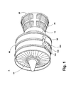
- an assembly 102 comprising the AGB 100 and the S/G 101 is schematically illustrated mounted to the gas turbine engine 1.
- This assembly is commonly referred to as an Integrated Starter/Generator Gearbox (ISGB).
- the gas turbine engine 1 comprises an air intake with a fan 50 at the air intake that supplies air to a high pressure compression region 60.
- the air intake with a fan 50 and the high pressure compression region collectively are known as the 'cold section' of the gas turbine engine upstream of the combustion.
- the high pressure compression region 60 provides the combustion chamber 10 with high pressure air. In the combustion chamber the high pressure air is mixed with fuel and combusted.
- the hot and pressurized combusted gas passes through a high pressure turbine region 20 and a low pressure turbine region 30 before exhausting from the gas turbine engine.
- the pressurized gases pass through the high pressure turbine (not shown) of the high pressure turbine region 20 and the low pressure turbine (not shown) of the low pressure turbine region 30 the turbines extract rotational energy from the flow of the gases passing through the gas turbine engine 1.
- the high pressure turbine of the high pressure turbine region 20 may be coupled to the compression mechanism (not shown) of the high pressure compression region 60 by way of a shaft to power the compression mechanism.
- the low pressure turbine may be coupled to the fan 50 of the air intake by way of a shaft to power the fan 50.
- the gas turbine engine may be a turbofan engine, such as a General Electric GEnx or CF6 series engine, commonly used in modem commercial and military aviation or it could be a variety of other known gas turbine engines such as a turboprop or turboshaft.
- the gas turbine engine may also have an afterburner that bums an additional amount of fuel downstream of the low pressure turbine region 30 to increase the velocity of the exhausted gases, and thereby increasing thrust.
- the accessory gearbox (AGB) 100 is coupled to a turbine shaft of the gas turbine engine 1, either to the low pressure or high pressure turbine by way of a mechanical power take off 90.
- the mechanical power take off contains multiple gears and means for mechanical coupling of the AGB 100 to the gas turbine engine.
- the assembly 102 may be mounted on the outside of either the air intake region containing the fan 50 or on the core near the high pressure compression region 60.
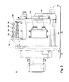
- FIG. 2 illustrates the S/G 101 according to one embodiment of the invention and which may be mounted to the AGB 100.
- the S/G 101 may be conceptually dividing into a first housing portion 110 that is external to the AGB 100 when the S/G is mounted on to the AGB 100, and a second housing portion 114 that nests within the AGB 100 when the S/G 101 is mounted on to the AGB 100.
- the electrical connections comprise a first power connector assembly 120 containing electrical power connections 122, 124, 126, and 128. These power connection may be for a three phase with ground reference output from the S/G 101.
- the electrical power connections 122, 124, 126, and 128 may be connected by cables to an electrical power distribution node of an aircraft to power various items on the aircraft, such as lights and seat-back monitors.
- the S/G 101 is oil cooled, and an oil inlet port 140 and an oil outlet port 144 are provided for controlling the supply of oil to and from the S/G.
- the cooling oil may be used to dissipate heat generated by the electrical and mechanical functions of the S/G.
- FIG. 3 is a sectional view of the S/G 101 coupled to the AGB 100.
- a rotatable shaft 170 is located within the S/G and is the primary structure for supporting a variety of components, including components, within the S/G.
- the diameter of the rotatable shaft 170 may be fixed or vary along the length of the rotatable shaft 170.
- the rotatable shaft 170 is supported by spaced bearings 180, 184.
- a pinion gear 150 is provided on the rotatable shaft 170 and engages a drive gear 171 (shown schematically as a box) in the AGB when the S/G 101 is coupled to the AGB 100.
- the drive gear is coupled by a gear train to the power take off 90. In this way, the power take off from the engine 1 may be used to drive the S/G 101 via the AGB 100.
- the components of the S/G 101 have a fixed component and a rotating component, with the rotating component being provided on the rotatable shaft 170.
- these components comprise a main machine 172, an exciter 176, and a PMG 174, with the corresponding rotating component comprising a main machine rotor 172a, an exciter rotor 176a, and a PMG rotor 174a, respectively, and the corresponding fixed component comprising a main machine stator 172b, an exciter stator 176b, and a PMG stator 174b.
- the fixed components may be mounted to any suitable part of either/both the first housing portion 110 and second housing portion 114.
- the exciter 176 provides direct current to the field windings of the main machine 172.
- the main machine 172 and PMG 174 supply AC electrical power when the rotatable shaft 170 rotates.
- the components may be any combination of known motors and generators.
- the main machine could be either a synchronous or asynchronous generator.
- the accessories shown in this embodiment there may be other components that may need to be operated for particular applications.
- there may be other accessories driven from the same rotatable shaft 170 such as an oil pump, a fluid compressor, or a hydraulic pump.
- the S/G 101 is attached to the AGB with a clamp 113 clamping the clamping interface 112 of the S/G 101 to the housing of the AGB 100.
- the first housing portion 110 of the S/G 101 is shown to be outside of the of the housing of the AGB 100 opening while a portion of the second housing portion 114 of the S/G 101 is nested within the opening of the housing of the AGB 100.
- the location of the exciter 176 and PMG 174 between the main machine 172 and the pinion gear 150 is beneficial in that it reduces the moment from the various accessories carried by the shaft and which act on the pinion gear 150 and its mating with the drive gear 171.
- the nesting of the S/G within the AGB further reduces the moment.
- This moment is commonly referred to as the overhung moment which is approximately equal to the distance between the pinion gear 150 to the center of mass of the assembly 102 multiplied by the weight of the assembly.
- High frequency switching of the magnetic field may also generate a high level of heat that is difficult to remove from the assembly 102.
- low pole count motors and generators are used within the S/G 101.
- the main machine may have a pole count as low as two.
- an assembly configuration 102 that minimizes the overhung moment of the assembly 102 and maximizes the rotational speed of the rotatable shaft 170 is desired to maximize power output.
- the relative locations of the PMG 174, exciter 176, and main machine 172 has an influence on the maximum critical rotational speed of the rotatable shaft 170 and the overhung moment of the assembly 102 of the S/G 101 mounted upon the AGB.
- the span of length between the spaced bearings 180 and 184 should be minimized.
- the PMG 174 with the PMG rotor 174a and PMG stator 174b is closest to the pinion gear 150 and the exciter 176 with the exciter rotor 176a and exciter stator 176b is between the PMG 174 and the main machine 172.
- the exciter 176 with the exciter rotor 176a and exciter stator 176b is closest to the pinion gear 150 and the PMG 174 with the PMG rotor 174a and PMG stator 174b is between the exciter and the main machine. All of the accessories are placed on the same side of the pinion gear 150 and the exciter 176 and the PMG 174 are placed closer to the pinion gear than the main machine 172.
- the spaced bearings 180 and 184 can be placed closer together, thereby allowing for a greater rotational velocity of the rotatable shaft 170.
- a greater rotational velocity in turn, produces a greater power output from low pole count generators.
- the overall weight of the assembly is reduced, thereby reducing the overhung moment of the assembly 102.
- portions of the S/G 101 containing the PMG 174 and/or the exciter 176 can be partially embedded within the opening of the AGB 100. By doing so, the center of mass of the assembly 102 moves closer to the pinion gear, thereby reducing the overhung moment of the assembly 102.
Landscapes
- Engineering & Computer Science (AREA)
- Chemical & Material Sciences (AREA)
- Combustion & Propulsion (AREA)
- Mechanical Engineering (AREA)
- General Engineering & Computer Science (AREA)
- Power Engineering (AREA)
- Aviation & Aerospace Engineering (AREA)
- Connection Of Motors, Electrical Generators, Mechanical Devices, And The Like (AREA)
Abstract
Description
- Gas turbine engines, also known as combustion turbine engines are rotary engines that extract energy from a flow of combusted gases passing through the engine onto a multitude of turbine blades. Gas turbine engines have been used for land and nautical locomotion and power generation, but are most commonly used for aeronautical applications such as for airplanes and helicopters. In airplanes gas turbine engines are used for propulsion of the aircraft.
- Gas turbine engines also usually power a number of different accessories such as generators, starter/generators, permanent magnet alternators (PMA), fuel pumps, and hydraulic pumps. All these equipment provide for functions needed on the aircraft other than moving the aircraft. For example, when the gas turbine engine is running the starter generator (S/G) produces electrical power and when the gas turbine needs to be started the S/G serves as a starting motor when provided energy from another energy source.
- One embodiment of the invention relates to an assembly for a gas turbine engine comprising an accessory gearbox, a drive gear, and a starter/generator mechanically mounted to the accessory gearbox. The starter/generator comprises a rotatable shaft, a pinion gear carried by the shaft, a main machine carried by the shaft, a permanent magnet generator (PMG) carried by the shaft and an exciter carried by the shaft. The PMG and exciter are located on the shaft between the pinion gear and the main machine, and the pinion gear meshes with the drive gear when the starter generator is mounted to the accessory gearbox.
- In the drawings:
-
FIG. 1 is a schematic illustration of a gas turbine engine with an accessory gearbox. -
FIG. 2 is a schematic view of the exterior of a starter/generator. -
FIG. 3 is a schematic cross-sectional view of the starter/generator mounted to the accessory gearbox. - The present invention is related to coupling of a starter/generator (S/G) containing more than one component on to an accessory gear box (AGB), also known as a transmission housing. The S/G mounted to the AGB has various applications including starting a gas turbine engine that the AGB is mechanically coupled to and to generate electrical power when the gas turbine engine is in operation.
- Referring to
FIG. 1 , anassembly 102 comprising theAGB 100 and the S/G 101 is schematically illustrated mounted to thegas turbine engine 1. This assembly is commonly referred to as an Integrated Starter/Generator Gearbox (ISGB). Thegas turbine engine 1 comprises an air intake with afan 50 at the air intake that supplies air to a highpressure compression region 60. The air intake with afan 50 and the high pressure compression region collectively are known as the 'cold section' of the gas turbine engine upstream of the combustion. The highpressure compression region 60 provides thecombustion chamber 10 with high pressure air. In the combustion chamber the high pressure air is mixed with fuel and combusted. The hot and pressurized combusted gas passes through a highpressure turbine region 20 and a lowpressure turbine region 30 before exhausting from the gas turbine engine. As the pressurized gases pass through the high pressure turbine (not shown) of the highpressure turbine region 20 and the low pressure turbine (not shown) of the lowpressure turbine region 30 the turbines extract rotational energy from the flow of the gases passing through thegas turbine engine 1. The high pressure turbine of the highpressure turbine region 20 may be coupled to the compression mechanism (not shown) of the highpressure compression region 60 by way of a shaft to power the compression mechanism. The low pressure turbine may be coupled to thefan 50 of the air intake by way of a shaft to power thefan 50. - The gas turbine engine may be a turbofan engine, such as a General Electric GEnx or CF6 series engine, commonly used in modem commercial and military aviation or it could be a variety of other known gas turbine engines such as a turboprop or turboshaft. The gas turbine engine may also have an afterburner that bums an additional amount of fuel downstream of the low
pressure turbine region 30 to increase the velocity of the exhausted gases, and thereby increasing thrust. - The accessory gearbox (AGB) 100 is coupled to a turbine shaft of the
gas turbine engine 1, either to the low pressure or high pressure turbine by way of a mechanical power take off 90. The mechanical power take off contains multiple gears and means for mechanical coupling of the AGB 100 to the gas turbine engine. Theassembly 102 may be mounted on the outside of either the air intake region containing thefan 50 or on the core near the highpressure compression region 60. -
FIG. 2 illustrates the S/G 101 according to one embodiment of the invention and which may be mounted to the AGB 100. The S/G 101 may be conceptually dividing into afirst housing portion 110 that is external to theAGB 100 when the S/G is mounted on to theAGB 100, and asecond housing portion 114 that nests within theAGB 100 when the S/G 101 is mounted on to theAGB 100. Aclamping interface 112, used to clamp the S/G 101 to theAGB 100. - Multiple electrical connections are provided on the exterior of the S/
G 101 to provide for the transfer of electrical power to and from the S/G 101. The electrical connections comprise a firstpower connector assembly 120 containingelectrical power connections G 101. Theelectrical power connections power connector assembly 130 comprisingelectrical connections G 101. - As illustrated, the S/G 101 is oil cooled, and an
oil inlet port 140 and anoil outlet port 144 are provided for controlling the supply of oil to and from the S/G. The cooling oil may be used to dissipate heat generated by the electrical and mechanical functions of the S/G. - The interior of the S/
G 101 is best seen inFIG. 3 , which is a sectional view of the S/G 101 coupled to theAGB 100. Arotatable shaft 170 is located within the S/G and is the primary structure for supporting a variety of components, including components, within the S/G. The diameter of therotatable shaft 170 may be fixed or vary along the length of therotatable shaft 170. Therotatable shaft 170 is supported byspaced bearings - One component, a
pinion gear 150, is provided on therotatable shaft 170 and engages a drive gear 171 (shown schematically as a box) in the AGB when the S/G 101 is coupled to theAGB 100. The drive gear is coupled by a gear train to the power take off 90. In this way, the power take off from theengine 1 may be used to drive the S/G 101 via the AGB 100. - Several of the components of the S/
G 101 have a fixed component and a rotating component, with the rotating component being provided on therotatable shaft 170. Examples of these components comprise amain machine 172, anexciter 176, and aPMG 174, with the corresponding rotating component comprising amain machine rotor 172a, anexciter rotor 176a, and aPMG rotor 174a, respectively, and the corresponding fixed component comprising amain machine stator 172b, anexciter stator 176b, and aPMG stator 174b. The fixed components may be mounted to any suitable part of either/both thefirst housing portion 110 andsecond housing portion 114. Theexciter 176 provides direct current to the field windings of themain machine 172. Themain machine 172 and PMG 174 supply AC electrical power when therotatable shaft 170 rotates. - The components may be any combination of known motors and generators. For example, the main machine could be either a synchronous or asynchronous generator. In addition to the accessories shown in this embodiment, there may be other components that may need to be operated for particular applications. For example, in addition to the electromechanical accessories shown, there may be other accessories driven from the same
rotatable shaft 170 such as an oil pump, a fluid compressor, or a hydraulic pump. - The S/
G 101 is attached to the AGB with aclamp 113 clamping theclamping interface 112 of the S/G 101 to the housing of theAGB 100. Thefirst housing portion 110 of the S/G 101 is shown to be outside of the of the housing of theAGB 100 opening while a portion of thesecond housing portion 114 of the S/G 101 is nested within the opening of the housing of theAGB 100. - The location of the
exciter 176 andPMG 174 between themain machine 172 and thepinion gear 150 is beneficial in that it reduces the moment from the various accessories carried by the shaft and which act on thepinion gear 150 and its mating with thedrive gear 171. The nesting of the S/G within the AGB further reduces the moment. - This moment is commonly referred to as the overhung moment which is approximately equal to the distance between the
pinion gear 150 to the center of mass of theassembly 102 multiplied by the weight of the assembly. - The value of these benefits become more clear when one understands and appreciates the spatial limitations of the S/
G 101 in a turbine engine environment, in which physical space is at a premium (reduced physical size ultimately means less aerodynamic drag the thrust must overcome and less weight an airplane must carry), and the required power output from the main machine. The spatial restrictions and power requirements tend to push design of the main machine toward lower pole counts, in that it reduces the overall weight and size of the S/G 101 and theoverall assembly 102. However, lower pole counts require faster rotational speeds to achieve the desired power output. Additionally, since soft materials such as silicon-iron alloys are commonly used, low pole counts help reduce excessive core losses that result from high frequency magnetic field switching. High frequency switching of the magnetic field may also generate a high level of heat that is difficult to remove from theassembly 102. As a result low pole count motors and generators are used within the S/G 101. In one embodiment the main machine may have a pole count as low as two. As a result of using low pole count motors and generators, anassembly configuration 102 that minimizes the overhung moment of theassembly 102 and maximizes the rotational speed of therotatable shaft 170 is desired to maximize power output. The relative locations of thePMG 174,exciter 176, andmain machine 172 has an influence on the maximum critical rotational speed of therotatable shaft 170 and the overhung moment of theassembly 102 of the S/G 101 mounted upon the AGB. - To maximize the rotational speed of the
rotatable shaft 170, the span of length between the spacedbearings exciter 176 and thePMG 174 closer to thepinion gear 150 than themain machine 172. In one embodiment thePMG 174 with thePMG rotor 174a andPMG stator 174b is closest to thepinion gear 150 and theexciter 176 with theexciter rotor 176a andexciter stator 176b is between thePMG 174 and themain machine 172. Alternatively, theexciter 176 with theexciter rotor 176a andexciter stator 176b is closest to thepinion gear 150 and thePMG 174 with thePMG rotor 174a andPMG stator 174b is between the exciter and the main machine. All of the accessories are placed on the same side of thepinion gear 150 and theexciter 176 and thePMG 174 are placed closer to the pinion gear than themain machine 172. - By placing all of the accessories on the same side of the
pinion gear 150, rather than splitting the accessories into two parts on either side of thepinion gear 150, the spacedbearings rotatable shaft 170. A greater rotational velocity, in turn, produces a greater power output from low pole count generators. By using a low pole count generator the overall weight of the assembly is reduced, thereby reducing the overhung moment of theassembly 102. Additionally, by placing thePMG 174 and theexciter 176 closer to thepinion gear 150, portions of the S/G 101 containing thePMG 174 and/or theexciter 176 can be partially embedded within the opening of theAGB 100. By doing so, the center of mass of theassembly 102 moves closer to the pinion gear, thereby reducing the overhung moment of theassembly 102. - This written description uses examples to disclose the invention, including the best mode, and also to enable any person skilled in the art to practice the invention, including making and using any devices or systems and performing any incorporated methods. The patentable scope of the invention is defined by the claims, and may include other examples that occur to those skilled in the art. Such other examples are intended to be within the scope of the claims if they have structural elements that do not differ from the literal language of the claims, or if they include equivalent structural elements with insubstantial differences from the literal languages of the claims.
- For completeness, various aspects of the invention are now set out in the following numbered clauses:
- Various aspects and embodiments of the present invention are defined by the following numbered clauses:
- 1. An assembly for a gas turbine engine comprising:
- an accessory gearbox comprising a drive gear;
- a starter/generator mechanically mounted to the accessory gearbox, comprising:
- a rotatable shaft;
- a pinion gear carried by the shaft;
- a main machine carried by the shaft;
- a permanent magnet generator (PMG) carried by the shaft;
- an exciter carried by the shaft;
- 2. The assembly of
clause 1 further comprising a first bearing rotatably supporting the shaft and the PMG and exciter are located on the shaft between the first bearing and the main machine. - 3. The assembly of clause 2 wherein the first bearing is located on the shaft between the pinion gear and the PMG and the exciter.
- 4. The assembly of clause 3 further comprising a second bearing rotatably supporting the shaft.
- 5. The assembly of clause 4 wherein at least one of the PMG, exciter, and main machine is located on the shaft between the first and second bearings.
- 6. The assembly of
clause 1 wherein the PMG is located on the shaft between the exciter and the pinion gear. - 7. The assembly of clause 6 wherein the first bearing is located on the shaft between the PMG and the pinion gear.
- 8. The assembly of
clause 1 wherein at least one of the PMG and exciter is located within the accessory gearbox when the starter/generator is mounted to the accessory gearbox. - 9. An assembly for a gas turbine engine comprising:
- an accessory gearbox comprising a first housing with an access opening and a drive gear located within the first housing;
- a starter/generator having a second housing mechanically mounted to the first housing, comprising:
- a pinion gear;
- a main machine;
- a permanent magnet generator (PMG);
- an exciter;
- a shaft rotatably mounted within the second housing and supporting the pinion gear, main machine, PMG, and exciter, with the PMG and exciter supported on the shaft between the pinion gear and the main machine;
- 10. The assembly of clause 9 further comprising a first bearing rotatably supporting the shaft and the PMG and exciter are located on the shaft between the first bearing and the main machine.
- 11. The assembly of
clause 10 wherein the first bearing is located on the shaft between the pinion gear and the PMG and the exciter. - 12. The assembly of clause 11 further comprising a second bearing rotatably supporting the shaft.
- 13. The assembly of clause 12 wherein at least one of the PMG, exciter, and main machine is located on the shaft between the first and second bearings.
- 14. The assembly of clause 13 wherein the PMG is located on the shaft between the exciter and the pinion gear.
- 15. The assembly of clause 14 wherein the first bearing is located on the shaft between the PMG and the pinion gear.
- 16. The assembly of clause 15 wherein at least one of the PMG and exciter is located within the accessory gearbox when the starter/generator is mounted to the accessory gearbox.
- 1. An assembly for a gas turbine engine comprising:
Claims (9)
- An assembly (102) for a gas turbine engine (1) comprising:an accessory gearbox (100) comprising a drive gear (171);a starter/generator (101) mechanically mounted to the accessory gearbox (100), comprising:a rotatable shaft (170);a pinion gear (150) carried by the shaft (170);a main machine (172) carried by the shaft (170);a permanent magnet generator (PMG) (174) carried by the shaft (170);an exciter (176) carried by the shaft (170);wherein the PMG (174) and exciter (176) are located on the shaft (170) between the pinion gear (150) and the main machine (172), and the pinion gear (170) meshes with the drive gear (171) when the starter/generator (101) is mounted to the accessory gearbox (100).
- The assembly (102) of claim 1, further comprising a first bearing (184) rotatably supporting the shaft (170) and the PMG (174) and exciter (176) are located on the shaft (170) between the first bearing (184) and the main machine (172).
- The assembly (102) of any of claims 1 or 2, wherein the first bearing (184) is located on the shaft (170) between the pinion gear (150) and the PMG (174) and the exciter (176).
- The assembly (102) of any of claims 1 to 3, further comprising a second bearing rotatably (180) supporting the shaft (170).
- The assembly (102) of any of claims 1 to 4, wherein at least one of the PMG (174), exciter (176), and main machine (172) is located on the shaft (170) between the first (184) and second bearings (180).
- The assembly (102) of any of claims 1 to 5, wherein the PMG (174) is located on the shaft (170) between the exciter (176) and the pinion gear (150).
- The assembly (102) of any of claims 1 to 6, wherein the first bearing (184) is located on the shaft (170) between the PMG (174) and the pinion gear (150).
- The assembly (102) of any of claims 1 to 7, wherein at least one of the PMG (174) and exciter (176) is located within the accessory gearbox (100) when the starter/generator (101) is mounted to the accessory gearbox (100).
- The assembly (102) of any of claims 1 to 8, wherein a portion of the starter/generator (101) housing (114) nests within an access opening of the accessory gearbox (100) when the starter/generator (101) is mounted to the accessory gearbox (100).
Applications Claiming Priority (1)
| Application Number | Priority Date | Filing Date | Title |
|---|---|---|---|
| US12/763,441 US8857192B2 (en) | 2010-04-20 | 2010-04-20 | Accessory gearbox with a starter/generator |
Publications (2)
| Publication Number | Publication Date |
|---|---|
| EP2381080A2 true EP2381080A2 (en) | 2011-10-26 |
| EP2381080A3 EP2381080A3 (en) | 2017-11-01 |
Family
ID=44117526
Family Applications (1)
| Application Number | Title | Priority Date | Filing Date |
|---|---|---|---|
| EP11162997.8A Withdrawn EP2381080A3 (en) | 2010-04-20 | 2011-04-19 | Accessory gearbox with a starter/generator |
Country Status (5)
| Country | Link |
|---|---|
| US (1) | US8857192B2 (en) |
| EP (1) | EP2381080A3 (en) |
| CN (1) | CN102235246B (en) |
| BR (1) | BRPI1101128A2 (en) |
| CA (1) | CA2736795A1 (en) |
Cited By (2)
| Publication number | Priority date | Publication date | Assignee | Title |
|---|---|---|---|---|
| WO2015189522A1 (en) * | 2014-06-12 | 2015-12-17 | Snecma | A turbine engine comprising a drive system for a device such as an accessories case |
| EP2651012A3 (en) * | 2012-04-13 | 2017-06-07 | Hamilton Sundstrand Corporation | Housing for an electrical starter motor |
Families Citing this family (30)
| Publication number | Priority date | Publication date | Assignee | Title |
|---|---|---|---|---|
| US9559569B2 (en) * | 2012-02-13 | 2017-01-31 | Ge Aviation Systems Llc | Arrangement for cooling an electric machine with a layer of thermally conducting and electrically insulating material |
| US8973465B2 (en) | 2012-07-20 | 2015-03-10 | United Technologies Corporation | Gearbox for gas turbine engine |
| WO2014046713A1 (en) * | 2012-09-20 | 2014-03-27 | United Technologies Corporation | Geared gas turbine engine accessory gearbox |
| CN103847973A (en) * | 2012-12-05 | 2014-06-11 | 石家庄飞机工业有限责任公司 | Small general-purpose aircraft power supply capacity expanding system |
| EP3741961B1 (en) * | 2013-01-30 | 2024-05-01 | RTX Corporation | Gas turbine engine accessory gearbox |
| EP3004564A4 (en) * | 2013-06-07 | 2016-11-23 | Ge Aviat Systems Llc | Turbofan engine with generator |
| CN103836127A (en) * | 2013-12-10 | 2014-06-04 | 贵州黎阳航空动力有限公司 | Starting device for two-level speed changing gas turbine |
| US10787967B2 (en) | 2014-08-12 | 2020-09-29 | Hamilton Sundstrand Corporation | Starter-generator modules for gas turbine engines |
| US9897010B2 (en) | 2015-03-30 | 2018-02-20 | Honeywell International Inc. | Air turbine starter systems including gearbox-integrated clutch modules and gas turbine engines employing the same |
| CN104989531B (en) * | 2015-06-23 | 2017-03-08 | 中国航空动力机械研究所 | A kind of bearing bore ventilating system |
| CN104890885B (en) * | 2015-06-23 | 2017-05-10 | 中国航空动力机械研究所 | Aero-generator mounting adapter and adapting mounting system |
| CN105545491B (en) * | 2015-12-25 | 2017-05-17 | 中国航空工业集团公司沈阳发动机设计研究所 | Gas turbine hydraulic starting method and gas turbine hydraulic system adopting gas turbine hydraulic starting method |
| CN105545490B (en) * | 2015-12-25 | 2017-05-17 | 中国航空工业集团公司沈阳发动机设计研究所 | Closed-loop gas turbine hydraulic starting method and gas turbine hydraulic system |
| US10519869B2 (en) * | 2016-04-25 | 2019-12-31 | United Technologies Corporation | Electrical and mechanical connections through firewall |
| US10100875B2 (en) | 2016-07-26 | 2018-10-16 | General Electric Company | Roller bearing and systems including such |
| US10030708B2 (en) | 2016-07-29 | 2018-07-24 | General Electric Company | Roller bearing cage for use in a gearbox |
| US10138940B2 (en) | 2016-08-09 | 2018-11-27 | General Electric Company | Roller bearing cage for use in a gearbox |
| US10305350B2 (en) | 2016-11-18 | 2019-05-28 | Cummins Power Generation Limited | Generator set integrated gearbox |
| EP3555446B1 (en) | 2016-12-15 | 2022-08-17 | GE Aviation Systems LLC | Air turbine starter with decoupler |
| US10400678B2 (en) | 2017-01-03 | 2019-09-03 | General Electric Company | Apparatus and system for light-weight, flexible double-helical gear |
| US10508731B2 (en) | 2017-01-05 | 2019-12-17 | General Electric Company | Apparatus and method for managing pinch loads on a gear |
| US10228024B2 (en) | 2017-01-10 | 2019-03-12 | General Electric Company | Reduced-weight bearing pins and methods of manufacturing such bearing pins |
| US10247298B2 (en) | 2017-01-10 | 2019-04-02 | General Electric Company | Resilient bearing pin and gear assemblies including resilient bearing pins |
| US10247297B2 (en) | 2017-01-18 | 2019-04-02 | General Electric Company | Apparatus for a gearbox with multiple scavenge ports |
| US10408304B2 (en) | 2017-02-07 | 2019-09-10 | General Electric Company | Gears having reduced roller element stresses and methods of manufacturing such gears |
| US10451113B2 (en) | 2017-05-18 | 2019-10-22 | General Electric Company | Bearing cages for roller bearing assemblies |
| US10260563B2 (en) | 2017-05-18 | 2019-04-16 | General Electric Company | Bearing cages for roller bearing assemblies |
| US10385961B2 (en) | 2017-10-25 | 2019-08-20 | General Electric Company | Planetary gear system |
| US10934931B2 (en) | 2018-06-22 | 2021-03-02 | Cummins Power Generation Limited | Integrated epicyclic gearbox and alternator |
| US10995675B2 (en) | 2019-02-19 | 2021-05-04 | Pratt & Whitney Canada Corp. | Gas turbine engine with accessory gearbox |
Family Cites Families (33)
| Publication number | Priority date | Publication date | Assignee | Title |
|---|---|---|---|---|
| GB839961A (en) | 1956-11-01 | 1960-06-29 | Bristol Siddeley Engines Ltd | Improvements in or relating to engine accessory mounting arrangements |
| GB1259776A (en) * | 1968-04-19 | 1972-01-12 | Plessey Co Ltd | Improvements in or relating to electrical machines |
| US3714779A (en) | 1970-09-28 | 1973-02-06 | Avco Corp | Gas turbine engine having a horizontal accessory gear box |
| US4473752A (en) | 1982-05-27 | 1984-09-25 | Lockheed Corporation | Aircraft engine starting with synchronous ac generator |
| US4525995A (en) | 1983-04-04 | 1985-07-02 | Williams International Corporation | Oil scavening system for gas turbine engine |
| US4683389A (en) * | 1985-12-23 | 1987-07-28 | Sundstrand Corporation | Oil scavenge system |
| US4724331A (en) | 1986-02-25 | 1988-02-09 | The Boeing Company | Method and apparatus for starting an aircraft engine |
| US4797590A (en) | 1987-11-09 | 1989-01-10 | Sundstrand Corporation | Brushless generator with minimal axial length |
| US5023537A (en) * | 1989-08-23 | 1991-06-11 | Sundstrand Corporation | Low frequency feeder fault protection |
| US4990807A (en) | 1989-09-19 | 1991-02-05 | Sundstrand Corporation | Integrated drive generator having magnet generator on second shaft |
| US5068590A (en) * | 1989-12-20 | 1991-11-26 | Sundstrand Corporation | Brushless generator having AC excitation in generating and starting modes |
| US5191254A (en) | 1991-09-19 | 1993-03-02 | Allied-Signal Inc. | Minimum length, air cooled ac generator arrangement |
| EP0540192A1 (en) | 1991-10-30 | 1993-05-05 | General Electric Company | Accessory drive assembly |
| US5267433A (en) * | 1992-03-25 | 1993-12-07 | Allied-Signal, Inc. | Air turbine starter having a dual clutch |
| US5555722A (en) | 1993-11-15 | 1996-09-17 | Sundstrand Corporation | Integrated APU |
| US6058791A (en) | 1998-03-19 | 2000-05-09 | Alliedsignal, Inc. | Accessory mechanical drive for a gas turbine engine |
| US6204577B1 (en) | 2000-01-05 | 2001-03-20 | Jeffrey Eliot Chottiner | Method and apparatus for space-saving installation of a starter-alternator |
| SE519200C2 (en) | 2001-06-05 | 2003-01-28 | Volvo Aero Corp | Gas turbine device with an arrangement for operating one or more auxiliary appliances |
| US6838778B1 (en) | 2002-05-24 | 2005-01-04 | Hamilton Sundstrand Corporation | Integrated starter generator drive having selective torque converter and constant speed transmission for aircraft having a constant frequency electrical system |
| US7131275B2 (en) | 2002-12-06 | 2006-11-07 | Hamilton Sundstrand | Gas turbine engine system having an electric starter motor with integral clutch |
| WO2005073540A1 (en) | 2004-01-30 | 2005-08-11 | Pratt & Whitney Canada Corp. | Compact configuration for attaching a fuel pump or other accessory to an accessory gearbox |
| US7063734B2 (en) | 2004-03-23 | 2006-06-20 | Pratt & Whitney Canada Corp. | Air/oil separation system and method |
| US20060087123A1 (en) | 2004-10-22 | 2006-04-27 | Stout David E | Dual-rotor, single input/output starter-generator |
| US7495361B2 (en) | 2004-11-05 | 2009-02-24 | Pratt & Whitney Canada Corp. | Electric machine arrangement |
| FR2880920B1 (en) | 2005-01-20 | 2007-07-06 | Snecma Moteurs Sa | DOUBLE-BODY TURBOMOTEUR WITH DRIVING MEANS FOR THE ACCESSORIES HOUSING |
| US7449795B2 (en) * | 2005-08-05 | 2008-11-11 | Siemens Energy, Inc. | Electric power generation system using a permanent magnet dynamoelectric machine for starting a combustion turbine and for generating uninterruptible excitation power |
| FR2897895A1 (en) | 2006-02-27 | 2007-08-31 | Hispano Suiza Sa | Transmission unit and starter-generator assembly for gas turbine, has synchronous generator and exciter placed on sides of pinion and with respective rotors mounted on shaft, and transmission unit and starter-generator placed in common case |
| US8013488B2 (en) | 2006-02-27 | 2011-09-06 | Hispano-Suiza | Integration of a starter/generator module in a gas turbine transmission housing |
| US7508086B2 (en) * | 2006-03-24 | 2009-03-24 | General Electric Company | Aircraft engine starter/generator and controller |
| FR2903451B1 (en) | 2006-07-07 | 2008-09-12 | Snecma Sa | TURBOMOTEUR WITH ALTERNATOR AND METHOD OF TRANSMITTING MOTION TO ALTERNATOR |
| FR2905414B1 (en) | 2006-08-29 | 2013-03-01 | Snecma | DEVICE FOR DRIVING THE ROTOR OF AN AUXILIARY EQUIPMENT OF A TURBOMOTEUR. |
| FR2911917B1 (en) * | 2007-01-31 | 2013-05-17 | Hispano Suiza Sa | DISTRIBUTED GAS TURBINE GENERATOR-STARTER ARCHITECTURE |
| US8876476B2 (en) * | 2010-11-16 | 2014-11-04 | Hamilton Sundstrand Corporation | Integrated accessory gearbox and engine starter |
-
2010
- 2010-04-20 US US12/763,441 patent/US8857192B2/en active Active
-
2011
- 2011-03-29 BR BRPI1101128-9A patent/BRPI1101128A2/en not_active IP Right Cessation
- 2011-04-07 CA CA2736795A patent/CA2736795A1/en not_active Abandoned
- 2011-04-19 CN CN201110107905.5A patent/CN102235246B/en active Active
- 2011-04-19 EP EP11162997.8A patent/EP2381080A3/en not_active Withdrawn
Non-Patent Citations (1)
| Title |
|---|
| None |
Cited By (4)
| Publication number | Priority date | Publication date | Assignee | Title |
|---|---|---|---|---|
| EP2651012A3 (en) * | 2012-04-13 | 2017-06-07 | Hamilton Sundstrand Corporation | Housing for an electrical starter motor |
| WO2015189522A1 (en) * | 2014-06-12 | 2015-12-17 | Snecma | A turbine engine comprising a drive system for a device such as an accessories case |
| FR3022301A1 (en) * | 2014-06-12 | 2015-12-18 | Snecma | TURBOMACHINE COMPRISING A DRIVE SYSTEM OF AN EQUIPMENT SUCH AS AN ACCESSORY HOUSING |
| US9982556B2 (en) | 2014-06-12 | 2018-05-29 | Safran Aircraft Engines | Turbine engine comprising a drive system for a device such as an accessories case |
Also Published As
| Publication number | Publication date |
|---|---|
| CA2736795A1 (en) | 2011-10-20 |
| CN102235246A (en) | 2011-11-09 |
| BRPI1101128A2 (en) | 2015-07-14 |
| CN102235246B (en) | 2015-06-03 |
| EP2381080A3 (en) | 2017-11-01 |
| US20110252807A1 (en) | 2011-10-20 |
| US8857192B2 (en) | 2014-10-14 |
Similar Documents
| Publication | Publication Date | Title |
|---|---|---|
| US8857192B2 (en) | Accessory gearbox with a starter/generator | |
| US9650964B2 (en) | Accessory gearbox with a starter/generator | |
| CN109562836B (en) | Electric propulsion system | |
| US6914344B2 (en) | Integrated starter/generator for a turbomachine | |
| US8198744B2 (en) | Integrated boost cavity ring generator for turbofan and turboshaft engines | |
| CA2612813C (en) | Electric power generation using power turbine aft of lpt | |
| CN113251111B (en) | Gearbox assembly with motor | |
| US20220003128A1 (en) | Dual rotor electric machine | |
| WO2022093414A1 (en) | A power generaton system | |
| US20250364872A1 (en) | Electric generator behind fan in turbine engine | |
| EP3020942B1 (en) | Gas turbine electrical machine arrangement | |
| US11988150B2 (en) | Bypass turbine engine comprising at least one accessory or equipment | |
| US12516633B2 (en) | Accessory power module | |
| US20240410293A1 (en) | Electric Generator Behind Fan in Turbine Engine | |
| US12523161B1 (en) | Aircraft powerplant gearbox with selectable power coupler | |
| EP4122817B1 (en) | Aircraft propulsion system | |
| EP4096069A1 (en) | Aircraft turbo-alternator | |
| CN121932286A (en) | Power transmission system |
Legal Events
| Date | Code | Title | Description |
|---|---|---|---|
| AK | Designated contracting states |
Kind code of ref document: A2 Designated state(s): AL AT BE BG CH CY CZ DE DK EE ES FI FR GB GR HR HU IE IS IT LI LT LU LV MC MK MT NL NO PL PT RO RS SE SI SK SM TR |
|
| AX | Request for extension of the european patent |
Extension state: BA ME |
|
| PUAI | Public reference made under article 153(3) epc to a published international application that has entered the european phase |
Free format text: ORIGINAL CODE: 0009012 |
|
| PUAL | Search report despatched |
Free format text: ORIGINAL CODE: 0009013 |
|
| AK | Designated contracting states |
Kind code of ref document: A3 Designated state(s): AL AT BE BG CH CY CZ DE DK EE ES FI FR GB GR HR HU IE IS IT LI LT LU LV MC MK MT NL NO PL PT RO RS SE SI SK SM TR |
|
| AX | Request for extension of the european patent |
Extension state: BA ME |
|
| RIC1 | Information provided on ipc code assigned before grant |
Ipc: H02K 7/116 20060101ALI20170928BHEP Ipc: F02C 7/36 20060101AFI20170928BHEP Ipc: H02K 19/38 20060101ALI20170928BHEP Ipc: F02C 7/275 20060101ALI20170928BHEP Ipc: B64D 41/00 20060101ALI20170928BHEP Ipc: F02C 7/32 20060101ALI20170928BHEP |
|
| STAA | Information on the status of an ep patent application or granted ep patent |
Free format text: STATUS: THE APPLICATION IS DEEMED TO BE WITHDRAWN |
|
| 18D | Application deemed to be withdrawn |
Effective date: 20180503 |